EP1501575B1 - Abgabevorrichtung für flüssigkeiten - Google Patents
Abgabevorrichtung für flüssigkeiten Download PDFInfo
- Publication number
- EP1501575B1 EP1501575B1 EP03720560A EP03720560A EP1501575B1 EP 1501575 B1 EP1501575 B1 EP 1501575B1 EP 03720560 A EP03720560 A EP 03720560A EP 03720560 A EP03720560 A EP 03720560A EP 1501575 B1 EP1501575 B1 EP 1501575B1
- Authority
- EP
- European Patent Office
- Prior art keywords
- fluid
- dispensing device
- container
- fluid dispensing
- nozzle
- Prior art date
- Legal status (The legal status is an assumption and is not a legal conclusion. Google has not performed a legal analysis and makes no representation as to the accuracy of the status listed.)
- Expired - Lifetime
Links
- 239000012530 fluid Substances 0.000 title claims abstract description 187
- 229920003023 plastic Polymers 0.000 claims description 22
- 239000004033 plastic Substances 0.000 claims description 21
- 239000003814 drug Substances 0.000 claims description 19
- 238000009472 formulation Methods 0.000 claims description 12
- 239000000203 mixture Substances 0.000 claims description 12
- 150000001875 compounds Chemical class 0.000 claims description 11
- 230000001681 protective effect Effects 0.000 claims description 11
- -1 2-furanylcarbonyl Chemical group 0.000 claims description 6
- 239000002253 acid Substances 0.000 claims description 6
- 239000003862 glucocorticoid Substances 0.000 claims description 6
- 238000007906 compression Methods 0.000 claims description 5
- 230000006835 compression Effects 0.000 claims description 5
- 238000005507 spraying Methods 0.000 claims description 5
- OIRDTQYFTABQOQ-KQYNXXCUSA-N adenosine Chemical compound C1=NC=2C(N)=NC=NC=2N1[C@@H]1O[C@H](CO)[C@@H](O)[C@H]1O OIRDTQYFTABQOQ-KQYNXXCUSA-N 0.000 claims description 4
- 230000003110 anti-inflammatory effect Effects 0.000 claims description 4
- 238000003780 insertion Methods 0.000 claims description 4
- 230000037431 insertion Effects 0.000 claims description 4
- 239000000725 suspension Substances 0.000 claims description 3
- 239000002126 C01EB10 - Adenosine Substances 0.000 claims description 2
- 108010059108 CD18 Antigens Proteins 0.000 claims description 2
- 102100029438 Nitric oxide synthase, inducible Human genes 0.000 claims description 2
- 101710089543 Nitric oxide synthase, inducible Proteins 0.000 claims description 2
- 229940123932 Phosphodiesterase 4 inhibitor Drugs 0.000 claims description 2
- 102000001400 Tryptase Human genes 0.000 claims description 2
- 108060005989 Tryptase Proteins 0.000 claims description 2
- 229960005305 adenosine Drugs 0.000 claims description 2
- 239000000556 agonist Substances 0.000 claims description 2
- 239000005557 antagonist Substances 0.000 claims description 2
- 239000003602 elastase inhibitor Substances 0.000 claims description 2
- 239000003112 inhibitor Substances 0.000 claims description 2
- 239000003199 leukotriene receptor blocking agent Substances 0.000 claims description 2
- 239000002587 phosphodiesterase IV inhibitor Substances 0.000 claims description 2
- 239000002750 tryptase inhibitor Substances 0.000 claims description 2
- 230000009471 action Effects 0.000 abstract description 6
- 239000000463 material Substances 0.000 description 8
- 230000007246 mechanism Effects 0.000 description 8
- 239000007921 spray Substances 0.000 description 6
- 238000000034 method Methods 0.000 description 5
- 230000036316 preload Effects 0.000 description 5
- 230000000694 effects Effects 0.000 description 4
- 230000004048 modification Effects 0.000 description 4
- 238000012986 modification Methods 0.000 description 4
- 230000008901 benefit Effects 0.000 description 3
- 210000003928 nasal cavity Anatomy 0.000 description 3
- 239000000126 substance Substances 0.000 description 3
- 238000011282 treatment Methods 0.000 description 3
- 239000004743 Polypropylene Substances 0.000 description 2
- 208000006673 asthma Diseases 0.000 description 2
- 238000005452 bending Methods 0.000 description 2
- 230000008859 change Effects 0.000 description 2
- 239000011521 glass Substances 0.000 description 2
- 208000027866 inflammatory disease Diseases 0.000 description 2
- 230000003993 interaction Effects 0.000 description 2
- 229920001155 polypropylene Polymers 0.000 description 2
- 206010039083 rhinitis Diseases 0.000 description 2
- 239000012780 transparent material Substances 0.000 description 2
- 206010027654 Allergic conditions Diseases 0.000 description 1
- 208000006545 Chronic Obstructive Pulmonary Disease Diseases 0.000 description 1
- 201000004624 Dermatitis Diseases 0.000 description 1
- 206010039094 Rhinitis perennial Diseases 0.000 description 1
- 208000036284 Rhinitis seasonal Diseases 0.000 description 1
- 230000001154 acute effect Effects 0.000 description 1
- 239000000654 additive Substances 0.000 description 1
- 230000000996 additive effect Effects 0.000 description 1
- 239000000853 adhesive Substances 0.000 description 1
- 230000001070 adhesive effect Effects 0.000 description 1
- 239000004479 aerosol dispenser Substances 0.000 description 1
- 239000007900 aqueous suspension Substances 0.000 description 1
- 239000003795 chemical substances by application Substances 0.000 description 1
- 230000001684 chronic effect Effects 0.000 description 1
- 230000000295 complement effect Effects 0.000 description 1
- 238000010276 construction Methods 0.000 description 1
- 229960000289 fluticasone propionate Drugs 0.000 description 1
- WMWTYOKRWGGJOA-CENSZEJFSA-N fluticasone propionate Chemical compound C1([C@@H](F)C2)=CC(=O)C=C[C@]1(C)[C@]1(F)[C@@H]2[C@@H]2C[C@@H](C)[C@@](C(=O)SCF)(OC(=O)CC)[C@@]2(C)C[C@@H]1O WMWTYOKRWGGJOA-CENSZEJFSA-N 0.000 description 1
- 230000004968 inflammatory condition Effects 0.000 description 1
- 230000002757 inflammatory effect Effects 0.000 description 1
- 239000012263 liquid product Substances 0.000 description 1
- 230000014759 maintenance of location Effects 0.000 description 1
- 210000000214 mouth Anatomy 0.000 description 1
- 239000000041 non-steroidal anti-inflammatory agent Substances 0.000 description 1
- 229940021182 non-steroidal anti-inflammatory drug Drugs 0.000 description 1
- 210000001331 nose Anatomy 0.000 description 1
- 238000010951 particle size reduction Methods 0.000 description 1
- 239000003755 preservative agent Substances 0.000 description 1
- 239000000047 product Substances 0.000 description 1
- 238000011321 prophylaxis Methods 0.000 description 1
- 238000005086 pumping Methods 0.000 description 1
- 238000007789 sealing Methods 0.000 description 1
- 230000001932 seasonal effect Effects 0.000 description 1
- 239000000375 suspending agent Substances 0.000 description 1
- 208000024891 symptom Diseases 0.000 description 1
- 239000000080 wetting agent Substances 0.000 description 1
Images




Classifications
-
- A—HUMAN NECESSITIES
- A61—MEDICAL OR VETERINARY SCIENCE; HYGIENE
- A61M—DEVICES FOR INTRODUCING MEDIA INTO, OR ONTO, THE BODY; DEVICES FOR TRANSDUCING BODY MEDIA OR FOR TAKING MEDIA FROM THE BODY; DEVICES FOR PRODUCING OR ENDING SLEEP OR STUPOR
- A61M15/00—Inhalators
- A61M15/08—Inhaling devices inserted into the nose
-
- A—HUMAN NECESSITIES
- A61—MEDICAL OR VETERINARY SCIENCE; HYGIENE
- A61M—DEVICES FOR INTRODUCING MEDIA INTO, OR ONTO, THE BODY; DEVICES FOR TRANSDUCING BODY MEDIA OR FOR TAKING MEDIA FROM THE BODY; DEVICES FOR PRODUCING OR ENDING SLEEP OR STUPOR
- A61M15/00—Inhalators
- A61M15/0001—Details of inhalators; Constructional features thereof
- A61M15/0021—Mouthpieces therefor
- A61M15/0025—Mouthpieces therefor with caps
- A61M15/0026—Hinged caps
-
- B—PERFORMING OPERATIONS; TRANSPORTING
- B05—SPRAYING OR ATOMISING IN GENERAL; APPLYING FLUENT MATERIALS TO SURFACES, IN GENERAL
- B05B—SPRAYING APPARATUS; ATOMISING APPARATUS; NOZZLES
- B05B11/00—Single-unit hand-held apparatus in which flow of contents is produced by the muscular force of the operator at the moment of use
- B05B11/01—Single-unit hand-held apparatus in which flow of contents is produced by the muscular force of the operator at the moment of use characterised by the means producing the flow
- B05B11/10—Pump arrangements for transferring the contents from the container to a pump chamber by a sucking effect and forcing the contents out through the dispensing nozzle
- B05B11/1042—Components or details
- B05B11/1052—Actuation means
- B05B11/1056—Actuation means comprising rotatable or articulated levers
-
- A—HUMAN NECESSITIES
- A61—MEDICAL OR VETERINARY SCIENCE; HYGIENE
- A61M—DEVICES FOR INTRODUCING MEDIA INTO, OR ONTO, THE BODY; DEVICES FOR TRANSDUCING BODY MEDIA OR FOR TAKING MEDIA FROM THE BODY; DEVICES FOR PRODUCING OR ENDING SLEEP OR STUPOR
- A61M2205/00—General characteristics of the apparatus
- A61M2205/07—General characteristics of the apparatus having air pumping means
- A61M2205/071—General characteristics of the apparatus having air pumping means hand operated
- A61M2205/073—Syringe, piston type
-
- B—PERFORMING OPERATIONS; TRANSPORTING
- B05—SPRAYING OR ATOMISING IN GENERAL; APPLYING FLUENT MATERIALS TO SURFACES, IN GENERAL
- B05B—SPRAYING APPARATUS; ATOMISING APPARATUS; NOZZLES
- B05B11/00—Single-unit hand-held apparatus in which flow of contents is produced by the muscular force of the operator at the moment of use
- B05B11/0005—Components or details
- B05B11/0037—Containers
- B05B11/0038—Inner container disposed in an outer shell or outer casing
Definitions
- the present invention relates to a medicament dispenser and in particular to fluid dispensing device for use as a nasal inhaler.
- a medicament dispenser in which fluid is dispensed via a nozzle or orifice upon the application of a force by a user to an actuation lever or button.
- Such devices may be arranged to dispense a single dose or may alternatively be arranged with a reservoir containing several doses to be dispensed.
- An example of such a pump action spray is shown and described in US Patent 4,771,769 .
- US-A-5 899 365 discloses a device for assisting the manual action of aerosol dispensers.
- FR-A-1 444 387 provides an actuator for use with small pressurised containers intended for spraying into the nasal or oral cavities.
- WO-A-00/07740 discloses a liquid product sprayer wherein a substantially radial thrust exerted on a flange thereof causes the product to be delivered.
- the fluid dispensing device may include a pre-load means which prevents movement of the two levers until more than a pre-determined force has been applied to the levers.
- Each of the levers may have an abutment surface arranged at an angle to the longitudinal axis of the fluid discharge device for abutment against the inclined surface(s) of the container so as to convert a force applied to the levers substantially transversely to the longitudinal axis of the fluid discharge device into a force along the longitudinal axis of the fluid discharge device.
- the nozzle may have a longitudinal axis and the longitudinal axis of the fluid discharge device may be aligned with the longitudinal axis of the nozzle.
- the inclined surface of the base portion of the container may be a conical surface, a frusto-conical surface or a spherically shaped surface.
- the base portion of the container may have two inclined surfaces each arranged for co-operation with a respective one of the levers.
- the container may have two or more supports to allow the container to be stood up on the base portion.
- the housing and the nozzle are made as a single plastic component.
- Each of the levers may be pivotally connected to part of the housing by a respective living hinge.
- the housing may have a front wall, a rear wall and two opposing side walls and each of the levers is pivotally connected to a respective one of the two side walls by a living hinge.
- At least one of the front wall and the rear wall may have an aperture therein to view the level of the fluid in the container.
- the discharge outlet from the pump may be a tubular delivery tube and a tubular guide may be formed within the nozzle to align and locate the delivery tube correctly with respect to the nozzle.
- the housing comprises of a plastic cover member and a plastic body member.
- the fluid dispensing device may include a means to prevent inadvertent movement of the two levers when not in use.
- the means may be a portion of the cover member which overlies an end portion of each lever.
- the nozzle may be formed as an integral part of the body member.
- At least a part of the nozzle may be moulded from a soft-touch plastics material.
- the body member may be fastened within the cover member so that the nozzle projects from one end of the cover member.
- Each of the levers may be pivotally connected to the body member.
- each of the levers may be pivotally connected to the body member by a living hinge.
- each of the levers may be pivotally connected to the cover member.
- the discharge outlet from the pump may be a tubular delivery tube and a tubular guide may be formed within the body member to align and locate the delivery tube correctly with respect to the nozzle.
- the cover member may comprise of two cover shells joined together at one end by an annular ring.
- the body member may be engaged with the annular ring to fasten the cover member to the body member.
- Each of the cover shells may have an aperture formed therein from which, in use, a part of a respective one of the levers projects.
- each lever which projects from the aperture may be a ribbed finger grip.
- a part of each lever may be moulded from a soft-touch plastics material.
- each lever may be moulded from a soft-touch plastics material is the ribbed finger grip.
- each cover shell may have a recess formed therein and the recesses may co-operate to define a window through which the level of the fluid in the container can be checked.
- each cover shell may have a recess formed therein and the recesses may co-operate to define two windows on opposite sides of the housing through which the level of the fluid in the container can be checked.
- a protective end cap for the nozzle may be connected to the annular ring.
- the protective end cap may be arranged to be biased to a closed position or may alternatively be biased to an open position.
- the end cap, the annular ring and the two cover shells may be made as a one piece plastic component.
- a fluid dispensing device 5 for spraying a fluid into a body cavity comprising a housing 9, a nozzle 11 for insertion into a body cavity, a fluid discharge device 8 moveably housed within the housing 9, the fluid discharge device 9 comprising a container 30 for storing the fluid to be dispensed and a compression pump 29 having a suction inlet 32 located within the container 30 and a discharge outlet 31 for transferring fluid from the pump 29 to the nozzle 11 and finger operable means 20, 21 to apply a force to the container 30 to move the container 30 towards the nozzle 11 so as to actuate the pump 29 .
- the finger operable means being in the form of two opposing levers 20, 21 each of which is pivotally connected to part of the housing 9 and is arranged to act upon a base portion 35 of the container 30 so as to urge the container 30 towards the nozzle 11 when the two levers 20, 21 are squeezed together by a user.
- the fluid dispensing device 5 comprises of a plastic moulded body 6 and the fluid discharge device 8 and further comprises of a protective end cap 7 having an inner surface for engagement with the body 6 to protect the dispensing nozzle 11.
- the body 6 is made from a plastic material such as polypropylene and defines a housing 9 and a dispensing nozzle 11 so that the housing 9 and the nozzle 11 are made as a single plastic component.
- the housing 9 defines a cavity 10 formed by a front wall 12, a rear wall 13 and first and second end walls 14a, 14b.
- the dispensing nozzle 11 is connected to one end of the housing 9, extends away from the housing 9 and has an external tapering form. It will be appreciated that the shape of the housing need not be oval it could be cylindrical or any other convenient shape.
- At least one of the front wall 12 and the rear wall 13 has an aperture 28 therein to view the level of the fluid in the container 30 and in the embodiment shown there are apertures 28 in the front and rear walls 12, and 13 to view the level of the fluid in the container 30.
- the discharge outlet from the pump 29 is in the form of a tubular delivery tube 31 and a tubular guide in the form of an outlet tube 16 is formed within the nozzle 11 to align and locate the delivery tube 31 correctly with respect to the nozzle 11.
- annular abutment 17 is formed at the end of the outlet tube 16.
- the annular abutment 17 defines the entry to an orifice 15 through which fluid can flow in use and is arranged for abutment with an end of the delivery tube 31.
- the fluid discharge device 8 has a longitudinal axis X-X and each of the levers 20, 21 has an abutment surface 22, 23 arranged at an angle ⁇ to the longitudinal axis X-X of the fluid discharge device 8 for abutment against a base portion 35 of the container so as to convert a force applied to the levers 20, 21 substantially transversely to the longitudinal axis X-X of the fluid discharge device 8 into a force along the longitudinal axis X-X of the fluid discharge device 8.
- This arrangement allows a standard fluid discharge device to be used without modification.
- the nozzle 11 has a longitudinal axis Y-Y and the longitudinal axis X-X of the fluid discharge device 8 is aligned with the longitudinal axis Y-Y of the nozzle 11.
- At least part of the surface of the base portion 35 of the container 30 is inclined at an angle ⁇ with respect to the longitudinal axis X-X of the fluid discharge device 8 so as to form an inclined surface, the or each inclined surface being arranged to be acted upon by the levers 20, 21 so as to convert a force applied to the levers 20, 21 substantially transversely to the longitudinal axis X-X of the fluid discharge device 8 into a force along the longitudinal axis X-X of the fluid discharge device 8.
- both the levers and the container have surfaces inclined to the longitudinal axis of the fluid discharge device and that in the disclosed embodiment the angle ⁇ is approximately equal to the angle ⁇ this need not be the case. Only the container need have an inclined surface.
- the base portion 35 of the container 30 has two inclined surfaces 37, 38 each arranged for co-operation with a respective one of the levers 20, 21.
- the inclined surface of the base portion of the container could be a conical, frusto-conical or part spherical surface.
- the inclined surface 37 is arranged to co-operate with the abutment surface 22 and the inclined surface 38 is arranged to co-operate with the abutment surface 23.
- the abutment surface 22 is formed by an edge of a web 24 formed as part of the lever 20 and the abutment surface 23 is formed by an edge of a web 25 formed as part of the lever 21.
- a pre-loading means in the form of small ridge (not shown) is formed near to the end of each abutment surface 22, 23. In the ready for use position this lies against a side of the container 30 at the juncture of the side of the container with the base portion 35.
- the purpose of this ridge is to prevent the levers 20, 21 from moving the container 30 until more than a pre-determined load has been applied to the levers 20, 21. Once this pre-determined load is exceeded the pressure being applied to the levers is such that the container is very rapidly moved towards the nozzle 11. This prevents the levers 20, 21 being slowly squeezed together which will not produce a uniform spray and if done very slowly will merely cause the fluid to dribble out of the nozzle 11.
- many alternative mechanisms could be employed to produce this pre-load effect and that the pump itself could be provided with such a device that needs to be overcome.
- Each of the levers 20, 21 is pivotally connected to part of the housing 9 by a respective living hinge.
- each of the levers 20, 21 is pivotally connected to a respective one of the two side walls 14a, 14b by a respective living hinge 26, 27.
- the fluid discharge device 8 is in most respects conventional and will only be described briefly herein.
- the fluid discharge device 8 has a hollow container 30 defining a reservoir containing several doses of the fluid to be dispensed and a compression pump 29 attached to one end of the container 30.
- the container 30 as shown is made from a translucent or transparent plastics material however it will be appreciate that it could be made from other translucent or transparent materials such as glass.
- the container has two or more supports to allow the container to be stood up on the base portion 35 and as shown two supports 40, 41 are moulded as an integral part of the container 30. These supports are useful in that, because the base portion 35 is made up of two inclined surfaces 37, 38, it could not normally be stood up vertically.
- the pump 29 includes a plunger (not shown) slidingly engaged within a pump casing 34 which defines a chamber (not shown) sized to accommodate a single dose of fluid.
- the plunger is attached to the tubular delivery tube 31 which is arranged to extend from one end of the pump 29 for co-operation with the outlet tube 16 of the dispensing nozzle 11.
- the plunger includes a piston (not shown) slidably supported in the chamber formed in the pump casing 34.
- the fluid is discharged through a discharge channel defined by the tubular delivery tube 31 into the orifice 15 of the dispensing nozzle 11.
- the size of chamber is such that it accommodates a single dose of fluid, the diameter of the chamber and piston combined with the stroke of the plunger being such that a full stroke of the plunger in the chamber will produce a change in volume equal to a single dose of fluid.
- the pump casing 34 is connected to the container 30 such that when the piston is moved by a return spring (not shown) into a start position a new dose of fluid is drawn into the cylinder via the suction inlet in the form of a pick-up tube 32 from the container 30 ready for discharge.
- the tapering form of the base portion 35 of the container 30 is advantageous in that it allows the pick up tube 32 to collect, without special orientation of the container, more fluid than if a flat bottomed container is used.
- the end cap 7 is a tubular component which is closed at one end and has a thin flexible side wall which defines a cavity into which the nozzle 11 is engaged to protect the nozzle 11 from damage.
- end cap may be attached to the body by a flexible strap or tether which could be moulded as part of the end cap or the end cap and the body could be made as a single component.
- Fig.4 shows the fluid dispensing device 5 in a partly assembled state in which the two levers 20,21 have been moved into a loading position to allow the fluid discharge device 8 to be inserted into the cavity 10 in the housing 9.
- the fluid discharge device 8 is moved upwardly until the delivery tube 31 fully engages with the outlet tube 16.
- the two levers 20, 21 are then folded down into the position shown in Fig. 1 such that end portions of the abutment surfaces 22, 23 abut gently against the inclined surfaces 37, 38 of the container 30.
- the levers 20, 21 in this position are used to hold the fluid discharge device 8 within the housing 9.
- the container 30 or the pump casing 34 could be slidably engageable with one or more support structures (not shown) to assist with the location and retention of the fluid discharge device 8 in the housing 9.
- a user first grasps the fluid dispensing device 5 by the two levers 20, 21. Provided that only a light pressure is applied to the levers 20, 21 no fluid will be discharged and the user is able to manoeuvre the dispensing nozzle 11 of the fluid dispensing device 5 into the body orifice into which fluid is required to be dispensed. This is because of the presence of the pre-loading means.
- the pre-determined load of the pre-loading means will eventually be overcome and the interaction of the abutment surfaces 22, 23 with the inclined surfaces 37, 38 will then cause the container 30 to be moved rapidly towards the nozzle 11 as indicated by the arrow ⁇ M' on Fig.5 .
- the abutment between the end of the delivery tube 31 and the annular abutment 17 will prevent movement of the delivery tube 31 in the same direction. This effect of this is to cause the delivery tube 31 to push the plunger into the pump casing 34 thereby moving the piston of the pump in the cylinder. This movement causes fluid to be expelled from the cylinder into the delivery tube 31. The fluid forced into the delivery tube is then transferred into the orifice 15 from where it is expelled as a fine spray into the body orifice.
- the delivery tube 31 Upon releasing the pressure applied to the levers 20, 21 the delivery tube 31 is urged out of the pump casing by the internal return spring and causes fluid to be drawn up the pick-up tube 32 to re-fill the cylinder.
- the actuating procedure can then be repeated until all of the fluid in the container has been used. However, only one or two doses of fluid are normally administered at a time.
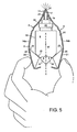
- FIG. 6 With reference to figures 6 to 11 there is shown a second embodiment of a fluid dispensing device for spraying a fluid into a body cavity which is in many respects similar to that previously described.
- the fluid dispensing device 105 comprising a housing 109, a nozzle 111 for insertion into a body cavity, a fluid discharge device 108 moveably housed within the housing 109, the fluid discharge device 108 comprising a container 130 for storing the fluid to be dispensed and a compression pump 129 having a suction inlet located within the container 130 and a discharge outlet for transferring fluid from the pump 129 to the nozzle 111 and finger operable means 120, 121 to apply a force to the container 130 to move the container 130 towards the nozzle 111 so as to actuate the pump 129.
- the finger operable means is in the form of two opposing levers 120, 121 each of which is pivotally connected to part of the housing 109 and is arranged to act upon the container 130 so as to urge the container 130 towards the nozzle 111 when the two levers 120, 121 are squeezed together by a user.
- the housing 109 comprises of a plastic cover member 110 and a plastic body member 106 both of which are moulded from a suitable plastic material such as polypropylene. It will be appreciated that the shape of the housing need not be oval it could be cylindrical or any other convenient shape.
- the nozzle 111 is formed as an integral part of the body member 106 and the body member 106 is fastened within the cover member 110 so that the nozzle 111 projects from one end of the cover member 110.
- the outer surface or a part of the outer surface of the nozzle could be made from a soft-touch plastics material.
- the cover member 110 comprises of two cover shells 118a, 118b joined together at one end by an annular ring 119.
- a protective end cap 107 for the nozzle 111 is connected to the annular ring 119 such that the end cap 107, the annular ring 119 and the two cover shells 118a, 118b are made as a one piece plastic component.
- the protective end cap may be moulded and arranged so as to be biased to a closed position or may alternatively be biased to an open position.
- the protective end cap 107 has an inner surface for engagement with the body 106 to protect the dispensing nozzle 111.
- Two detents 149 are provided on the inner surface of the end cap 107 to releasably hold the end cap 107 in place when it is in its protective position.
- the end cap 107 has a tubular sealing means 140 which is arranged for engagement with a recess 141 in the end of the nozzle 111 so as to prevent leakage from the nozzle 111 when the end cap 107 is in place.
- Each of the cover shells 118a and 118b is of a semi-cylindrical shape and has two longitudinal edges 112, an end edge 113 and two transverse edges 116. At least one longitudinal edge 112 of each cover shell 118a, 118b has a recess 114 formed therein. The recesses 114 co-operate to define a window 150 through which the level of the fluid in the container 130 can be checked.
- each cover shell 118a, 118b have a recess 114 formed therein and the recesses 114 co-operate to define two windows 150 on opposite sides of the housing 109 through which the level of the fluid in the container 130 can be checked.
- Each of the cover shells 118a, 118b has an aperture 145a, 145b formed therein from which, in use, a part of a respective one of the levers 120, 121 projects.
- the part of each lever 120, 121 which projects from the aperture 145a, 145b is a ribbed finger grip 146 formed at the opposite end of each lever 120, 121 from where it is hingedly connected to the body member 106.
- a part of each lever and in particular the finger grips may be moulded from a soft touch plastic material.
- the fluid dispensing device includes a means to prevent inadvertent movement of the two levers when not in use.
- the means is a portion of each cover member 118a, 118b which overlies an end portion of each lever 120,121. More specifically, each of the cover shells 118a, 118b extends around the base portion of the cover to provide an overlying shield 200.
- the shields 200 act as a means to prevent inadvertent movement of the two levers 120, 121.
- the body member 106 is engaged with the annular ring 119 to fasten the cover member 110 to the body member 106.
- the body member 106 has a cylindrical portion for engagement with the annular ring 119.
- Two detents 143 are formed on the cylindrical portion and two legs 144 are connected near to one end of the cylindrical portion.
- the detents 143 are used to trap the annular ring 119 against the legs 144 and thereby form a snap connection used to fasten the body member 106 to the cover member 110. It will be appreciated that other forms of snap fastening means could be provided.
- Each of the levers 20, 121 is pivotally connected to the body member 106 by a living hinge 126, 127.
- the living hinges 126, 127 are formed at the juncture of the levers 120, 121 with the legs 144.
- the discharge outlet from the pump 129 is in the form of a tubular delivery tube (not shown) and a tubular guide in the form of an outlet tube (not shown) is formed within the nozzle 111 to align and locate the delivery tube correctly with respect to the nozzle 111.
- annular abutment is formed at the end of the outlet tube.
- the annular abutment defines the entry to an orifice 115 through which fluid can flow in use and is arranged for abutment with an end of the delivery tube.
- the fluid discharge device 108 has a longitudinal axis Z-Z and each of the levers 120, 121 has an abutment surface 122 (only one of which is visible in the Figures) arranged at an angle to the longitudinal axis Z-Z of the fluid discharge device 108 for abutment against a base portion 135 of the container so as to convert a force applied to the levers 120, 121 substantially transversely to the longitudinal axis Z-Z of the fluid discharge device 108 into a force along the longitudinal axis Z-Z of the fluid discharge device 108.
- This arrangement allows a standard fluid discharge device to be used without modification.
- the nozzle 111 has a longitudinal axis P-P and the longitudinal axis Z-Z of the fluid discharge device 108 is aligned with the longitudinal axis P-P of the nozzle 111. This has the advantage that when the pump 129 is actuated the force applied to the tubular delivery tube is along the axis of the tubular delivery tube and no bending or deflection of the delivery tube will occur due to the applied force.
- At least part of the surface of the base portion 135 of the container 130 is inclined at an angle with respect to the longitudinal axis Z-Z of the fluid discharge device 108 so as to form an inclined surface, the or each inclined surface being arranged to be acted upon by the levers 120, 121 so as to convert a force applied to the levers 120, 121 substantially transversely to the longitudinal axis Z-Z of the fluid discharge device 108 into a force along the longitudinal axis Z-Z of the fluid discharge device 108.
- both the levers and the container have surfaces inclined to the longitudinal axis of the fluid discharge device this need not be the case. Only the container need have an inclined surface.
- the base portion 135 of the container has a conical inclined surface 138 arranged for co-operation with the levers 120, 121.
- the inclined surface of the base portion of the container could be a frusto-conical or part spherical surface or could be comprised of two separate inclined surfaces each for co-operation with a respective one of the levers.
- the inclined surface 138 is arranged to co-operate with both abutment surfaces 122 of the levers 120, 121.
- the abutment surfaces 122 are both formed by one surface of triangular web 124 formed as part of each lever 120, 121.
- a pre-loading means in the form of a ridge 170 (only one of which is shown). The purpose of this ridge 170 is to introduce a pre-load effect into the mechanism which has to be overcome by applying more than a pre-determined load to allow the fluid to be dispensed.
- this ridge In the ready for use position this lies against a side of the container 130 at the juncture of the side of the container 130 with the base portion 135.
- the purpose of this ridge is to prevent the levers 120, 121 from moving the container 130 until more than a pre-determined load has been applied to the levers 120, 121. Once this pre-determined load is exceeded the pressure being applied to the levers is such that the container 130 is very rapidly moved towards the nozzle 111. This prevents the levers 120, 121 being slowly squeezed together which will not produce a uniform spray and if done very slowly will merely cause the fluid to dribble out of the nozzle 111.
- many alternative mechanisms could be employed to produce this pre-load effect. For example the angle of contact could be such that until the levers have been displaced or deflected the force is not efficiently transferred or the levers could be prevented from movement by some form of detent mechanism or the pump itself could be provided with a mechanism that needs to be overcome.
- the fluid discharge device 108 is in most respects conventional and will only be described briefly herein.
- the fluid discharge device 108 has a hollow container 130 defining a reservoir containing several doses of the fluid to be dispensed and a compression pump 129 attached to one end of the container 130.
- the container 130 as shown is made from glass however it will be appreciated that it could be made from other translucent or transparent materials such as plastic.
- the pump 129 includes a plunger (not shown) slidingly engaged within a pump casing 134 which defines a chamber (not shown) sized to accommodate a single dose of fluid.
- the plunger is attached to the tubular delivery tube which is arranged to extend from one end of the pump 129 for co-operation with the outlet tube of the dispensing nozzle 111.
- the plunger includes a piston (not shown) slidably supported in the chamber formed in the pump casing 134.
- the fluid is discharged through a discharge channel defined by the tubular delivery tube into the orifice 115 of the dispensing nozzle 111.
- the size of chamber is such that it accommodates a single dose of fluid, the diameter of the chamber and piston combined with the stroke of the plunger being such that a full stroke of the plunger in the chamber will produce a change in volume equal to a single dose of fluid.
- the pump casing 134 is connected to the container 130 such that when the piston is moved by an internal return spring (not shown) into a start position a new dose of fluid is drawn into the cylinder via the suction inlet in the form of a pick-up tube from the container 130 ready for discharge.
- the conical form of the base portion 135 of the container 130 is particularly advantageous in that it allows the pick up tube to collect more fluid, without special orientation of the container, than if a flat bottomed container is used.
- the first stage of assembly is to position the levers 120, 121 in the position shown in Fig. 9 and then insert the fluid discharge device 108 into the body member 106.
- Fig.11 shows the fluid dispensing device 105 in a partly assembled state after this initial assembly operation in which the fluid discharge device 108 has been inserted into the body member 106.
- the two levers 120, 121 have been folded down from the position shown in Fig. 9 into a ready for use position such that end portions of the abutment surfaces 122 and in particular the ridges 170 are positioned adjacent to a side wall of the container and near to the inclined conical surface 138 of the container 130.
- the cylindrical portion of the body member 106 is inserted into the annular ring 119 and the two parts are snapped together.
- the two cover shells 118a and 118b are then folded down from the position shown in Fig. 10 into the position shown in Fig 6 .
- the abutting transverse edges 116 of the two cover shells 118a and 118b include complementary detents (not shown) such that when the cover shells 118a, 118b are pushed together the detents snap together to hold them in the position shown in Figs 6 and 7 .
- an adhesive backed label (not shown) can be applied across the joint between the two cover shells 118a and 118b on the base on the assembled fluid dispensing device 105 to prevent the cover shells 118a, 118b from accidentally snapping open but more importantly to provide an indication that the fluid dispensing device 105 has not been tampered with.
- a user To use the fluid dispensing device 105 a user first has to remove the protective cap 107 (as shown in Fig. 7 ) and then the user must grasp the fluid dispensing device 105 by the two levers 120, 121 and in particular by the two ribbed finger grips 146.
- the delivery tube acts so as to push the plunger into the pump casing 134 thereby moving the piston of the pump in the cylinder. This causes fluid to be expelled from the cylinder into the delivery tube and then into the orifice 115 from where it is expelled as a fine spray into the body orifice.
- the delivery tube Upon releasing the pressure applied to the levers 120, 121 the delivery tube is urged out of the pump casing by the internal return spring and causes fluid to be drawn up the pick-up tube to re-fill the cylinder.
- the actuating procedure can then be repeated until all of the fluid in the container has been used. However, only one or two doses of fluid are normally administered at a time.
- the fluid dispensing device could be sold as two separate items.
- a fluid discharge device could be sold for fitment into a housing assembly and a housing assembly could be sold into which a fluid discharge device could be fitted.
- the two embodiments describe in detail an arrangement in which the two levers act upon a base portion of the container and push it towards the nozzle it would also possible to arrange for the two leavers to pull the container towards the nozzle.
- the invention is not therefore to be construed as being limited solely to a device that pushes the container towards the nozzle.
- Administration of medicament may be indicated for the treatment of mild, moderate or severe acute or chronic symptoms or for prophylactic treatment. It will be appreciated that the precise dose administered will depend on the age and condition of the patient, the particular medicament used and the frequency of administration and will ultimately be at the discretion of the attendant physician. When combinations of medicaments are employed the dose of each component of the combination will in general be that employed for each component when used alone.
- the medicament is an anti-inflammatory compound for the treatment of inflammatory disorders or diseases such as asthma and rhinitis.
- the medicament is a glucocorticoid compound, which has anti-inflammatory properties.
- glucocorticoid compound has the chemical name: 6 ⁇ , 9 ⁇ -Difluoro-17 ⁇ -(1-oxopropoxy)-11 ⁇ -hydroxy-16 ⁇ -methyl-3-oxo-androsta-1,4-diene-17 ⁇ -carbothioic acid S-fluoromethyl ester (fluticasone propionate).
- Another suitable glucocorticoid compound has the chemical name: 6 ⁇ , 9 ⁇ -difluoro-17 ⁇ -[(2-furanylcarbonyl)oxy]-11 ⁇ -hydroxy-16 ⁇ -methyl-3-oxo-androsta-1,4-diene-17 ⁇ -carbothioic acid S-fluoromethyl ester.
- a further suitable glucocorticoid compound has the chemical name: 6 ⁇ ,9 ⁇ -Difluoro-11 ⁇ -hydroxy-16 ⁇ -methyl-17 ⁇ -[(4-methyl-1,3-thiazole-5-carbonyl)oxy]-3-oxo-androsta-1,4-diene-17 ⁇ -carbothioic acid S-fluoromethyl ester.
- NSAIDs e.g. PDE4 inhibitors, leukotriene antagonists, iNOS inhibitors, tryptase and elastase inhibitors, beta-2 integrin antagonists and adenosine 2a agonists.
- the medicament is formulated as any suitable fluid formulation, particularly a solution (e.g. aqueous) formulation or a suspension formulation, optionally containing other pharmaceutically acceptable additive components.
- a solution e.g. aqueous
- a suspension formulation optionally containing other pharmaceutically acceptable additive components.
- Suitable suspension formulations comprise an aqueous suspension of particulate medicament and optionally suspending agents, preservatives, wetting agents or isotonicity adjusting agents.
- the particulate medicament suitably has a mass mean diameter (MMD) of less than 20 ⁇ m, preferably between 0.5-10 ⁇ m, especially between 1-s ⁇ m. If particle size reduction is necessary, this may be achieved by techniques such as micronisation and/or microfluidisation.
- MMD mass mean diameter
- the dispensing device herein is suitable for dispensing fluid medicament formulations for the treatment of inflammatory and/or allergic conditions of the nasal passages such as rhinitis e.g. seasonal and perennial rhinitis as well as other local inflammatory conditions such as asthma, COPD and dermatitis.
- rhinitis e.g. seasonal and perennial rhinitis
- other local inflammatory conditions such as asthma, COPD and dermatitis.
- a suitable dosing regime would be for the patient to inhale slowly through the nose subsequent to the nasal cavity being cleared. During inhalation the formulation would be applied to one nostril while the other is manually compressed. This procedure would then be repeated for the other nostril. Typically, one or two inhalations per nostril would be administered by the above procedure up to three times each day, ideally once daily. Each dose, for example, may deliver 5 ⁇ g, 50 ⁇ g, 100 ⁇ g, 200 ⁇ g or 250 ⁇ g of active medicament. The precise dosage is either known or readily ascertainable by those skilled in the art.
Landscapes
- Health & Medical Sciences (AREA)
- Engineering & Computer Science (AREA)
- Hematology (AREA)
- Life Sciences & Earth Sciences (AREA)
- Pulmonology (AREA)
- Anesthesiology (AREA)
- Biomedical Technology (AREA)
- Heart & Thoracic Surgery (AREA)
- Veterinary Medicine (AREA)
- Bioinformatics & Cheminformatics (AREA)
- Animal Behavior & Ethology (AREA)
- General Health & Medical Sciences (AREA)
- Public Health (AREA)
- Otolaryngology (AREA)
- Containers And Packaging Bodies Having A Special Means To Remove Contents (AREA)
- Nozzles (AREA)
- Physical Or Chemical Processes And Apparatus (AREA)
Claims (32)
- Flüssigkeitsabgabeeinrichtung (5; 105) zum Sprühen einer Flüssigkeit in eine Körperöffnung, umfassend ein Gehäuse (9; 109), eine Düse (11; 111) zum Einsetzen in eine Körperöffnung, eine Flüssigkeitsausstoßeinrichtung (8; 108), die eine Längsachse (X-X; Z-Z) aufweist und die für eine Längsbewegung innerhalb des Gehäuses bewegbar aufgenommen ist, wobei die Flüssigkeitsausstoßeinrichtung einen'Behälter (30; 130) für die Lagerung der abzugebenden Flüssigkeit und eine Druckpumpe (29; 129) umfasst, die einen Saugeinlass (32), der innerhalb des Behälters angeordnet ist, und einen Ausstoßauslass (31) zum Überführen der Flüssigkeit von der Pumpe zu der Düse und fingerbetätigbare Mittel zum Aufbringen einer Kraft auf den Behälter aufweist, um den Behälter entgegen der Düse zu bewegen, so dass die Pumpe betrieben wird,
bei der die fingerbetätigbaren Mittel zwei gegenüberliegende Hebel (20, 21; 120, 121) umfassen, von denen jeder schwenkbar mit einem Teil des Gehäuses verbunden und so angeordnet ist, dass er so auf den Behälter wirkt, dass er den Behälter entgegen der Düse drängt, wenn die beiden Hebel durch einen Nutzer zusammengedrückt werden,
bei der zumindest ein Teil der Oberfläche eines Basisabschnitts (35; 135) des Behälters in einem Winkel (Φ) in Bezug auf die Längsachse der Flüssigkeitsausstoßeinrichtung so geneigt ist, dass sie eine geneigte Oberfläche (37, 38; 138) ausbildet, wobei die oder jede geneigte Oberfläche derart angeordnet ist, dass auf sie die die Hebel wirken, so dass eine auf die Hebel im Wesentlichen schräg zur Längsachse der Flüssigkeitsausstoßeinrichtung aufgebrachte Kraft in eine Kraft entlang der Längsachse der Flüssigkeitsausstoßeinrichtung umgewandelt wird. - Flüssigkeitsabgabeeinrichtung nach Anspruch 1, bei der jeder der Hebel eine Anstoßoberfläche (22, 23; 122, 123) aufweist, die in einem Winkel zur Längsachse der Flüssigkeitsausstoßeinrichtung angeordnet ist, zum Anstoßen gegen die geneigte(n) Oberfläche(n); so dass eine auf die Hebel in einer im wesentlichen schrägen Richtung zur Längsachse der Flüssigkeitsausstoßeinrichtung aufgebrachte Kraft in eine Kraft entlang der Längsachse der Flüssigkeitsausstoßeinrichtung umgewandelt ist.
- Flüssigkeitsabgabeeinrichtung nach Anspruch 2, bei der die Düse eine Längsachse aufweist und die Längsachse der Flüssigkeitsausstoßeinrichtung mit der Längsachse der Düse ausgerichtet ist.
- Flüssigkeitsabgabeeinrichtung nach Anspruch 1, 2 oder 3, bei der die geneigte Oberfläche (138) des Basisabschnitts (135) des Behälters eine konische Oberfläche (138) ist.
- Flüssigkeitsabgabeeinrichtung nach Anspruch 1, 2 oder 3, bei der der Basisabschnitt (35) des Behälters zwei geneigte Oberflächen (37, 38) aufweist, von denen jede für das Zusammenwirken mit einem jeweiligen der Hebel angeordnet ist.
- Flüssigkeitsabgabeeinrichtung nach einem der Ansprüche 4 oder 5, bei der der Behälter zwei oder mehrere Lagerungen (40, 41) aufweist, um dem Behälter zu ermöglichen auf dem Basisabschnitt zu stehen.
- Flüssigkeitsabgabeeinrichtung nach einem der vorhergehenden Ansprüche, bei der das Gehäuse und die Düse als einzelne Kunststoffkomponente hergestellt sind.
- Flüssigkeitsabgabeeinrichtung nach Anspruch 7, bei der jeder der Hebel schwenkbar mit einem Teil des Gehäuses durch ein jeweiliges dynamisches Gelenk (26, 27) verbunden ist.
- Flüssigkeitsabgabeeinrichtung nach Anspruch 7, bei der das Gehäuse eine Vorderwand (12), eine Rückwand (13) und zwei gegenüberliegende Seitenwände (14a, 14b) aufweist, und jeder der Hebel durch ein dynamisches Gelenk schwenkbar mit einer der zwei Seitenwände verbunden ist.
- Flüssigkeitsabgabeeinrichtung nach Anspruch 9, bei der zumindest die Vorderwand oder die Rückwand eine Öffnung (30) aufweist, um den Flüssigkeitsstand in dem Behälter zu betrachten.
- Flüssigkeitsabgabeeinrichtung nach Anspruch 10, bei der in der Vorder- und Rückwand Öffnungen sind, um den Flüssigkeitsstand in dem Behälter zu betrachten.
- Flüssigkeitsabgabeeinrichtung nach einem der vorhergehenden Ansprüche, bei der Ausstoßauslass der Pumpe ein röhrenförmiger Versorgungskanal ist und eine röhrenförmige Führung (16) innerhalb der Düse ausgebildet ist, um den Versorgungskanal korrekt in Bezug auf die Düse auszurichten und anzuordnen.
- Flüssigkeitsabgabeeinrichtung nach einem der Ansprüche 1 bis 6, bei der das Gehäuse ein Kunststoffabdeckungselement (110) und ein Kunststoffkörperelement (106) umfasst.
- Flüssigkeitsabgabeeinrichtung nach Anspruch 13, bei der die Düse (111) als ein integrales Teil des Körperelements ausgebildet ist.
- Flüssigkeitsabgabeeinrichtung nach Anspruch 14, bei der das Körperelement innerhalb des Abdeckungselements derart befestigt ist, dass die Düse von einem Ende des Abdeckungselements hervorsteht.
- Flüssigkeitsabgabeeinrichtung nach Anspruch 14 oder Anspruch 15, bei der jeder der Hebel durch ein dynamisches Gelenk schwenkbar mit dem Körperelement verbunden ist.
- Flüssigkeitsabgabeeinrichtung nach einem der Ansprüche 13 bis 16, bei der die Flüssigkeitsausstoßeinrichtung der Pumpe ein röhrenförmiger Versorgungskanal ist und eine röhrenförmige Führung innerhalb des Körperelements ausgebildet ist, um den Versorgungskanal korrekt in Bezug auf die Düse auszurichten und anzuordnen.
- Flüssigkeitsabgabeeinrichtung nach einem der Ansprüche 13 bis 17, bei der das Abdeckungselement zwei Abdeckungsmäntel (118a, 118b) umfasst, die an einem Ende durch einen kreisförmigen Ring (119) miteinander verbunden sind.
- Flüssigkeitsabgabeeinrichtung nach Anspruch 18, bei der das Körperelement mit dem kreisförmigen Ring eingreift um das Abdeckungselement an dem Körperelement zu befestigen.
- Flüssigkeitsabgabeeinrichtung nach Anspruch 18 oder Anspruch 19, bei der in jeden der Abdeckungsmäntel eine Öffnung (145a, 145b) ausgebildet ist, von der, im Gebrauch, ein Teil eines jeweiligen Hebels (120, 121) hervorsteht.
- Flüssigkeitsabgabeeinrichtung nach Anspruch 20, bei der der Teil des Hebels, der von der Öffnung hervorsteht, ein gerippter Fingergriff ist (146).
- Flüssigkeitsabgabeeinrichtung nach einem der Ansprüche 18 bis 21, bei der zumindest in eine Längskante (112) jedes Abdeckungsmantels eine Aussparung (114) ausgebildet ist und die Aussparungen so zusammenwirken, dass sie ein Fenster (150) definieren, durch das der Flüssigkeitsstand in dem Behälter kontrolliert werden kann.
- Flüssigkeitsabgabeeinrichtung nach Anspruch 22, bei der in beide Längskanten (112) jedes Abdeckungsmantels eine Aussparung (114) ausgebildet ist und die Aussparungen so zusammenwirken, dass sie zwei Fenster (150) auf gegenüberliegenden Seiten des Gehäuses definieren, durch das der Flüssigkeitsstand in dem Behälter kontrolliert werden kann.
- Flüssigkeitsabgabeeinrichtung nach einem der Ansprüche 18 bis 23, bei der eine schützende Endkappe (107) für die Düse mit dem kreisförmigen Ring verbunden ist.
- Flüssigkeitsabgabeeinrichtung nach Anspruch 24, bei der die Endkappe, der kreisförmige Ring und die zwei Abdeckungsmäntel als eine Kunststoffstückkomponente hergestellt sind.
- Flüssigkeitsabgabeeinrichtung nach einem der Ansprüche 1 bis 25, bei der der Behälter ein Volumen einer flüssigen Medikamentenrezeptur enthält.
- Flüssigkeitsabgabeeinrichtung nach Anspruch 26, bei der die Medikamentenrezeptur in Form einer Lösungsrezeptur ist.
- Flüssigkeitsabgabeeinrichtung nach Anspruch 26, bei der die Medikamentenrezeptur in Form einer Suspensionsrezeptur ist.
- Flüssigkeitsabgabeeinrichtung nach einem der Ansprüche 26 bis 28, bei der die Medikamentenrezeptur einen antientzündbaren Medikamentenbestandteil umfasst.
- Flüssigkeitsabgabeeinrichtung nach Anspruch 29, bei der der Medikamentenbestandteil ein Glucocorticoidbestandteil ist.
- Flüssigkeitsabgabeeinrichtung nach Anspruch 30, bei der der Glucocorticoidbestandteil aus einer Gruppe ausgewählt wird, die aus 6α, 9α-Difluor-17α-(1-oxopropoxy)-11β-hydroxy-16α-Methyl-3-oxo-androsta-1,4-diene-17β-carbothioic Säure S-Fluormethylesther; 6α, 9α-Difluor-17α-[(2-Furanylcarbonyl)oxy]-11β-hydroxy-16α-Methyl-3-oxo-androsta-1, 4-diene-17β-carbothioic Säure S-Fluormethylesther; und 6α, 9α-Difluor-17α-11β-hydroxy-16α-Methyl-17α-[(4-Methyl-1,2-thiazole-5-carbonyl)oxy]-3-oxo-androsta-1, 4-diene-17β-carbothioic Säure S-Fluormethylesther besteht.
- Flüssigkeitsabgabeeinrichtung nach Anspruch 29, bei der der Medikamentenbestandteil aus einer Gruppe ausgewählt wird, die aus PDE4 Inhibitoren, leukotriene Antagonisten, iNOS Inhibitoren, tryptase und elastase Inhibitoren, beta-2 integrin Antagonisten und adenosine 2a Antagonisten besteht.
Applications Claiming Priority (3)
| Application Number | Priority Date | Filing Date | Title |
|---|---|---|---|
| GB0210605 | 2002-05-09 | ||
| GBGB0210605.2A GB0210605D0 (en) | 2002-05-09 | 2002-05-09 | A fluid dispensing device |
| PCT/EP2003/004857 WO2003095006A2 (en) | 2002-05-09 | 2003-05-07 | A fluid dispensing device |
Publications (2)
| Publication Number | Publication Date |
|---|---|
| EP1501575A2 EP1501575A2 (de) | 2005-02-02 |
| EP1501575B1 true EP1501575B1 (de) | 2009-08-19 |
Family
ID=9936343
Family Applications (1)
| Application Number | Title | Priority Date | Filing Date |
|---|---|---|---|
| EP03720560A Expired - Lifetime EP1501575B1 (de) | 2002-05-09 | 2003-05-07 | Abgabevorrichtung für flüssigkeiten |
Country Status (9)
| Country | Link |
|---|---|
| US (1) | US7798368B2 (de) |
| EP (1) | EP1501575B1 (de) |
| JP (1) | JP2005524493A (de) |
| CN (1) | CN101596335B (de) |
| AT (1) | ATE439884T1 (de) |
| AU (1) | AU2003224152A1 (de) |
| DE (1) | DE60328883D1 (de) |
| GB (1) | GB0210605D0 (de) |
| WO (1) | WO2003095006A2 (de) |
Families Citing this family (43)
| Publication number | Priority date | Publication date | Assignee | Title |
|---|---|---|---|---|
| US8347879B2 (en) | 2002-05-09 | 2013-01-08 | Glaxo Group Limited | Fluid dispensing device |
| GB0305583D0 (en) * | 2003-03-11 | 2003-04-16 | Glaxo Group Ltd | A fluid dispensing device |
| CN1901958B (zh) * | 2003-11-03 | 2011-03-09 | 葛兰素集团有限公司 | 流体分配装置 |
| GB0405477D0 (en) | 2004-03-11 | 2004-04-21 | Glaxo Group Ltd | A fluid dispensing device |
| GB0327112D0 (en) * | 2003-11-21 | 2003-12-24 | Clincial Designs Ltd | Dispenser and reservoir |
| CA2559080A1 (en) | 2004-03-10 | 2005-09-22 | Glaxo Group Limited | A dispensing device |
| DE102004023528B4 (de) * | 2004-05-13 | 2007-05-31 | Meadwestvaco Calmar Gmbh | Manuell betätigbarer Spender mit Schutzkappe |
| GB0507224D0 (en) | 2005-04-09 | 2005-05-18 | Glaxo Group Ltd | A fluid dispensing device |
| SE529956C2 (sv) * | 2005-07-12 | 2008-01-15 | Medux Ab | Sprejanordning, metod för sprejning samt sätt för tillverkning av anordning |
| GB0518355D0 (en) | 2005-09-08 | 2005-10-19 | Glaxo Group Ltd | An inhaler |
| US20080203116A1 (en) * | 2007-02-28 | 2008-08-28 | Lagace Chad E | Metering dispenser |
| DE102007016503A1 (de) * | 2007-03-26 | 2008-10-02 | Ing. Erich Pfeiffer Gmbh | Austragvorrichtung für Medien |
| US20080302826A1 (en) * | 2007-06-09 | 2008-12-11 | Rich Jr Joseph | Plunger tube |
| US20090198199A1 (en) * | 2008-02-01 | 2009-08-06 | Drug Enhancement Company Of America, Llc | Inert container and dispenser |
| FR2932400B1 (fr) * | 2008-06-17 | 2011-11-18 | Valois Sas | Dispositif de distribution de produit fluide |
| JP5288404B2 (ja) * | 2008-09-26 | 2013-09-11 | 株式会社吉野工業所 | 点鼻薬噴出器 |
| JP5278946B2 (ja) * | 2008-09-30 | 2013-09-04 | 株式会社吉野工業所 | 点鼻薬噴出器 |
| GB2464282A (en) * | 2008-10-08 | 2010-04-14 | Archimedes Dev Ltd | A device for administering a dose of opioid analgesic |
| CA2741281A1 (en) * | 2008-11-03 | 2010-06-03 | Schering Corporation | Light blocking container with viewing window for photosensitive compounds |
| US9061817B2 (en) * | 2008-11-12 | 2015-06-23 | Meadwestvaco Calmar, Inc. | Spray devices and methods for using the same |
| DE102010042740A1 (de) * | 2010-10-21 | 2012-04-26 | Ing. Erich Pfeiffer Gmbh | Austragvorrichtung für Medien |
| USD666099S1 (en) | 2010-11-01 | 2012-08-28 | Colgate-Palmolive Company | Cap for a container |
| USD666097S1 (en) | 2010-11-01 | 2012-08-28 | Colgate-Palmolive Company | Cap for a container |
| USD666096S1 (en) | 2010-11-01 | 2012-08-28 | Colgate-Palmolive Company | Cap for a container |
| USD666098S1 (en) | 2010-11-01 | 2012-08-28 | Colgate-Palmolive Company | Cap for a container |
| USD666492S1 (en) | 2010-11-01 | 2012-09-04 | Colgate-Palmolive Company | Cap for a container |
| USD666493S1 (en) | 2010-11-01 | 2012-09-04 | Colgate-Palmolive Company | Cap for a container |
| US9486592B2 (en) * | 2011-10-27 | 2016-11-08 | Victor Esteve | Medicine dispensing device |
| DE102012023216A1 (de) * | 2012-11-28 | 2014-05-28 | Meadwestvaco Calmar Gmbh | Austragvorrichtung für ein fluides Medium |
| FR3003481B1 (fr) * | 2013-03-19 | 2020-05-15 | Aptar France Sas | Dispositif de distribution de produit fluide. |
| CN205597112U (zh) * | 2013-12-20 | 2016-09-28 | 雷特罗品牌有限责任公司 | 电子烟油分配器及电子烟油瓶 |
| US9745107B2 (en) | 2013-12-20 | 2017-08-29 | Retro Brands, Llc | E-liquid dispenser |
| USD765908S1 (en) | 2013-12-20 | 2016-09-06 | Retro Brands, Llc | E-liquid dispenser and bottle combination |
| US20160038692A1 (en) * | 2014-08-06 | 2016-02-11 | Andrej Bahoric | Internally controlled cell spray dispenser |
| US10482365B1 (en) * | 2017-11-21 | 2019-11-19 | Wells Fargo Bank, N.A. | Transaction instrument containing metal inclusions |
| JP7128150B2 (ja) * | 2019-05-30 | 2022-08-30 | 株式会社吉野工業所 | 吐出容器 |
| EP3753432A1 (de) * | 2019-06-21 | 2020-12-23 | Nerudia Limited | Aerosolabgabevorrichtung |
| US12369639B2 (en) | 2019-06-21 | 2025-07-29 | Imperial Tobacco Limited | Aerosol delivery device |
| CN110329624B (zh) * | 2019-08-14 | 2024-03-08 | 金东敏 | 定量挤压的胶水瓶 |
| US20220313895A1 (en) * | 2019-08-14 | 2022-10-06 | Gsk Consumer Healthcare Sarl | Bi-material nozzle for nasal washes |
| FR3110898B1 (fr) * | 2020-05-27 | 2024-03-15 | Coradin Sas | Ensemble compose d’un recipient pour un fluide et d’un emballage distributeur |
| GB2617328A (en) * | 2022-03-31 | 2023-10-11 | Consort Medical Ltd | Fluid delivery device |
| US20230381800A1 (en) * | 2022-05-31 | 2023-11-30 | Oyster Point Pharma, Inc. | Nasal spray guide |
Family Cites Families (28)
| Publication number | Priority date | Publication date | Assignee | Title |
|---|---|---|---|---|
| GB659132A (en) | 1949-04-19 | 1951-10-17 | Rotherham & Sons Ltd | Squirting or spraying devices |
| US2568286A (en) * | 1950-08-14 | 1951-09-18 | Ernest C Littlefield | Tube dispensing device having pivotally mounted housing members with transversely slidable pressure plates mounted therein |
| GB1097254A (en) | 1964-07-15 | 1968-01-03 | Neotechnic Eng Ltd | Improvements in or relating to actuators for pressurised aerosol dispensing containers |
| US3272391A (en) * | 1965-02-18 | 1966-09-13 | Meshberg Philip | Actuator for dispensing package |
| US4083476A (en) * | 1973-11-30 | 1978-04-11 | Boehringer Ingelheim Gmbh | Snap device for manually actuated liquid-atomizing pumps |
| US4771769A (en) | 1982-12-20 | 1988-09-20 | Schering Corporation | Hand held metered spray dispenser |
| US5062549A (en) * | 1989-11-03 | 1991-11-05 | Dowbrands Inc. | Hand held, dip-tube style liquid dispenser |
| GB2251898A (en) * | 1990-11-29 | 1992-07-22 | D M W | Metered dose spray system |
| GB9026191D0 (en) * | 1990-12-01 | 1991-01-16 | Harris Pharma Ltd | Breath actuated dispensing device |
| US5377869A (en) | 1992-08-27 | 1995-01-03 | Weiss; Stephan | Pump dispenser with movable bottle |
| US5529219A (en) * | 1994-02-18 | 1996-06-25 | Ward; Lloyd L. | Apparatus for storing and dispensing laundry soap |
| DE4436051C2 (de) * | 1994-10-10 | 1996-08-14 | Boehringer Ingelheim Kg | Vorrichtung zum Betätigen von Aerosolabgabegeräten |
| JPH0948455A (ja) * | 1995-08-09 | 1997-02-18 | Masashi Yuasa | バスソープ容器 |
| DE19610456B4 (de) | 1996-03-16 | 2006-10-19 | Ing. Erich Pfeiffer Gmbh | Austragvorrichtung für Medien |
| DE19622124A1 (de) * | 1996-06-01 | 1997-12-04 | Alfred Von Schuckmann | Gerät zum Aufbringen von Flüssigkeiten |
| DE19756442A1 (de) * | 1997-12-18 | 1999-06-24 | Pfeiffer Erich Gmbh & Co Kg | Spender für Medien |
| SE9801077D0 (sv) * | 1998-03-27 | 1998-03-27 | Shl Medical Ab | Inhalator |
| IE980530A1 (en) * | 1998-06-30 | 2000-02-09 | Loctite R & D Ltd | Device for Expressing Substances from a Deformable Tube |
| FR2781772B1 (fr) * | 1998-07-31 | 2000-10-13 | Sofab | Distributeur de produits liquides destines a etre delivres par pulverisation |
| JP2000085867A (ja) | 1998-09-16 | 2000-03-28 | Matsuyama Hideo | 詰め替え用包装体及びそのポンプ付きホルダー |
| FR2807954B1 (fr) | 2000-04-20 | 2003-09-26 | Cmc Jean Louis Vermeil | Vaporisateur a actionnement lateral |
| DE10032976A1 (de) * | 2000-07-06 | 2002-01-17 | Pfeiffer Erich Gmbh & Co Kg | Austragvorrichtung für Medien |
| FR2812826B1 (fr) * | 2000-08-11 | 2003-04-18 | Valois Sa | Dispositif de pulverisation a actionnement lateral, en particulier poussoir nasal |
| FR2813592B1 (fr) | 2000-09-07 | 2003-03-21 | Valois Sa | Dispositif de distribution de produit fluide du type monodose ou bidose |
| US6745760B2 (en) * | 2001-05-15 | 2004-06-08 | Trudell Medical International | Medicament applicator |
| FR2826422B1 (fr) | 2001-06-26 | 2003-11-14 | Serapid France | Actionneur lineaire a courroie |
| FR2830519B1 (fr) | 2001-10-04 | 2004-08-27 | Valois Sa | Dispositif de distribution de produit fluide a actionnement lateral |
| FR2830522B1 (fr) * | 2001-10-04 | 2004-02-13 | Tebro | Dispositif de distribution de produit fluide a actionnement lateral |
-
2002
- 2002-05-09 GB GBGB0210605.2A patent/GB0210605D0/en not_active Ceased
-
2003
- 2003-05-07 AT AT03720560T patent/ATE439884T1/de not_active IP Right Cessation
- 2003-05-07 AU AU2003224152A patent/AU2003224152A1/en not_active Abandoned
- 2003-05-07 JP JP2004503085A patent/JP2005524493A/ja active Pending
- 2003-05-07 DE DE60328883T patent/DE60328883D1/de not_active Expired - Lifetime
- 2003-05-07 WO PCT/EP2003/004857 patent/WO2003095006A2/en not_active Ceased
- 2003-05-07 EP EP03720560A patent/EP1501575B1/de not_active Expired - Lifetime
- 2003-05-07 US US10/513,200 patent/US7798368B2/en not_active Expired - Lifetime
- 2003-05-07 CN CN2009101395430A patent/CN101596335B/zh not_active Expired - Lifetime
Also Published As
| Publication number | Publication date |
|---|---|
| GB0210605D0 (en) | 2002-06-19 |
| CN101596335A (zh) | 2009-12-09 |
| US7798368B2 (en) | 2010-09-21 |
| CN101596335B (zh) | 2012-09-05 |
| WO2003095006A2 (en) | 2003-11-20 |
| AU2003224152A1 (en) | 2003-11-11 |
| JP2005524493A (ja) | 2005-08-18 |
| EP1501575A2 (de) | 2005-02-02 |
| DE60328883D1 (de) | 2009-10-01 |
| US20050211241A1 (en) | 2005-09-29 |
| WO2003095006A3 (en) | 2004-04-01 |
| ATE439884T1 (de) | 2009-09-15 |
Similar Documents
| Publication | Publication Date | Title |
|---|---|---|
| US7798368B2 (en) | Fluid dispensing device | |
| US4771769A (en) | Hand held metered spray dispenser | |
| RU2270701C2 (ru) | Дозирующее устройство (варианты) | |
| AU2004218872B2 (en) | A fluid dispensing device with stopper | |
| AU2003253367B2 (en) | A fluid dispensing device | |
| US6745760B2 (en) | Medicament applicator | |
| JP5558248B2 (ja) | 流体分配装置 | |
| EP0702575B1 (de) | Vorrichtung zum verabreichen von pharmazeutischen substanzen | |
| EP1539366B1 (de) | Ausgabevorrichtung | |
| KR101316637B1 (ko) | 유체 분배기 | |
| CN101723143A (zh) | 流体分配装置 | |
| US20050234402A1 (en) | Fluid dispensing device | |
| SK280225B6 (sk) | Inhalátor s odmerným dávkovaním a jeho použitie | |
| US20090200335A1 (en) | Spray Device, Method for Spraying a Certain Quantity of Fluid and a Process for Manufacturing the Device | |
| AU2007202884A1 (en) | A fluid dispensing device |
Legal Events
| Date | Code | Title | Description |
|---|---|---|---|
| PUAI | Public reference made under article 153(3) epc to a published international application that has entered the european phase |
Free format text: ORIGINAL CODE: 0009012 |
|
| 17P | Request for examination filed |
Effective date: 20041025 |
|
| AK | Designated contracting states |
Kind code of ref document: A2 Designated state(s): AT BE BG CH CY CZ DE DK EE ES FI FR GB GR HU IE IT LI LU MC NL PT RO SE SI SK TR |
|
| AX | Request for extension of the european patent |
Extension state: AL LT LV MK |
|
| RAX | Requested extension states of the european patent have changed |
Extension state: LV Payment date: 20041025 Extension state: LT Payment date: 20041025 |
|
| 17Q | First examination report despatched |
Effective date: 20070112 |
|
| GRAP | Despatch of communication of intention to grant a patent |
Free format text: ORIGINAL CODE: EPIDOSNIGR1 |
|
| GRAS | Grant fee paid |
Free format text: ORIGINAL CODE: EPIDOSNIGR3 |
|
| GRAA | (expected) grant |
Free format text: ORIGINAL CODE: 0009210 |
|
| AK | Designated contracting states |
Kind code of ref document: B1 Designated state(s): AT BE BG CH CY CZ DE DK EE ES FI FR GB GR HU IE IT LI LU MC NL PT RO SE SI SK TR |
|
| AX | Request for extension of the european patent |
Extension state: LT LV |
|
| REG | Reference to a national code |
Ref country code: GB Ref legal event code: FG4D |
|
| REG | Reference to a national code |
Ref country code: CH Ref legal event code: EP |
|
| REG | Reference to a national code |
Ref country code: IE Ref legal event code: FG4D |
|
| REF | Corresponds to: |
Ref document number: 60328883 Country of ref document: DE Date of ref document: 20091001 Kind code of ref document: P |
|
| LTIE | Lt: invalidation of european patent or patent extension |
Effective date: 20090819 |
|
| PG25 | Lapsed in a contracting state [announced via postgrant information from national office to epo] |
Ref country code: SE Free format text: LAPSE BECAUSE OF FAILURE TO SUBMIT A TRANSLATION OF THE DESCRIPTION OR TO PAY THE FEE WITHIN THE PRESCRIBED TIME-LIMIT Effective date: 20090819 Ref country code: FI Free format text: LAPSE BECAUSE OF FAILURE TO SUBMIT A TRANSLATION OF THE DESCRIPTION OR TO PAY THE FEE WITHIN THE PRESCRIBED TIME-LIMIT Effective date: 20090819 Ref country code: ES Free format text: LAPSE BECAUSE OF FAILURE TO SUBMIT A TRANSLATION OF THE DESCRIPTION OR TO PAY THE FEE WITHIN THE PRESCRIBED TIME-LIMIT Effective date: 20091130 Ref country code: AT Free format text: LAPSE BECAUSE OF FAILURE TO SUBMIT A TRANSLATION OF THE DESCRIPTION OR TO PAY THE FEE WITHIN THE PRESCRIBED TIME-LIMIT Effective date: 20090819 |
|
| NLV1 | Nl: lapsed or annulled due to failure to fulfill the requirements of art. 29p and 29m of the patents act | ||
| PG25 | Lapsed in a contracting state [announced via postgrant information from national office to epo] |
Ref country code: NL Free format text: LAPSE BECAUSE OF FAILURE TO SUBMIT A TRANSLATION OF THE DESCRIPTION OR TO PAY THE FEE WITHIN THE PRESCRIBED TIME-LIMIT Effective date: 20090819 Ref country code: SI Free format text: LAPSE BECAUSE OF FAILURE TO SUBMIT A TRANSLATION OF THE DESCRIPTION OR TO PAY THE FEE WITHIN THE PRESCRIBED TIME-LIMIT Effective date: 20090819 |
|
| PG25 | Lapsed in a contracting state [announced via postgrant information from national office to epo] |
Ref country code: BG Free format text: LAPSE BECAUSE OF FAILURE TO SUBMIT A TRANSLATION OF THE DESCRIPTION OR TO PAY THE FEE WITHIN THE PRESCRIBED TIME-LIMIT Effective date: 20091119 Ref country code: CY Free format text: LAPSE BECAUSE OF FAILURE TO SUBMIT A TRANSLATION OF THE DESCRIPTION OR TO PAY THE FEE WITHIN THE PRESCRIBED TIME-LIMIT Effective date: 20090819 Ref country code: PT Free format text: LAPSE BECAUSE OF FAILURE TO SUBMIT A TRANSLATION OF THE DESCRIPTION OR TO PAY THE FEE WITHIN THE PRESCRIBED TIME-LIMIT Effective date: 20091221 |
|
| PG25 | Lapsed in a contracting state [announced via postgrant information from national office to epo] |
Ref country code: CZ Free format text: LAPSE BECAUSE OF FAILURE TO SUBMIT A TRANSLATION OF THE DESCRIPTION OR TO PAY THE FEE WITHIN THE PRESCRIBED TIME-LIMIT Effective date: 20090819 Ref country code: RO Free format text: LAPSE BECAUSE OF FAILURE TO SUBMIT A TRANSLATION OF THE DESCRIPTION OR TO PAY THE FEE WITHIN THE PRESCRIBED TIME-LIMIT Effective date: 20090819 Ref country code: EE Free format text: LAPSE BECAUSE OF FAILURE TO SUBMIT A TRANSLATION OF THE DESCRIPTION OR TO PAY THE FEE WITHIN THE PRESCRIBED TIME-LIMIT Effective date: 20090819 Ref country code: DK Free format text: LAPSE BECAUSE OF FAILURE TO SUBMIT A TRANSLATION OF THE DESCRIPTION OR TO PAY THE FEE WITHIN THE PRESCRIBED TIME-LIMIT Effective date: 20090819 |
|
| PG25 | Lapsed in a contracting state [announced via postgrant information from national office to epo] |
Ref country code: SK Free format text: LAPSE BECAUSE OF FAILURE TO SUBMIT A TRANSLATION OF THE DESCRIPTION OR TO PAY THE FEE WITHIN THE PRESCRIBED TIME-LIMIT Effective date: 20090819 |
|
| PLBE | No opposition filed within time limit |
Free format text: ORIGINAL CODE: 0009261 |
|
| STAA | Information on the status of an ep patent application or granted ep patent |
Free format text: STATUS: NO OPPOSITION FILED WITHIN TIME LIMIT |
|
| PG25 | Lapsed in a contracting state [announced via postgrant information from national office to epo] |
Ref country code: BE Free format text: LAPSE BECAUSE OF FAILURE TO SUBMIT A TRANSLATION OF THE DESCRIPTION OR TO PAY THE FEE WITHIN THE PRESCRIBED TIME-LIMIT Effective date: 20090819 |
|
| 26N | No opposition filed |
Effective date: 20100520 |
|
| PG25 | Lapsed in a contracting state [announced via postgrant information from national office to epo] |
Ref country code: GR Free format text: LAPSE BECAUSE OF FAILURE TO SUBMIT A TRANSLATION OF THE DESCRIPTION OR TO PAY THE FEE WITHIN THE PRESCRIBED TIME-LIMIT Effective date: 20091120 |
|
| PG25 | Lapsed in a contracting state [announced via postgrant information from national office to epo] |
Ref country code: MC Free format text: LAPSE BECAUSE OF NON-PAYMENT OF DUE FEES Effective date: 20100531 |
|
| REG | Reference to a national code |
Ref country code: CH Ref legal event code: PL |
|
| PG25 | Lapsed in a contracting state [announced via postgrant information from national office to epo] |
Ref country code: LI Free format text: LAPSE BECAUSE OF NON-PAYMENT OF DUE FEES Effective date: 20100531 Ref country code: CH Free format text: LAPSE BECAUSE OF NON-PAYMENT OF DUE FEES Effective date: 20100531 |
|
| PG25 | Lapsed in a contracting state [announced via postgrant information from national office to epo] |
Ref country code: IT Free format text: LAPSE BECAUSE OF FAILURE TO SUBMIT A TRANSLATION OF THE DESCRIPTION OR TO PAY THE FEE WITHIN THE PRESCRIBED TIME-LIMIT Effective date: 20090819 |
|
| PG25 | Lapsed in a contracting state [announced via postgrant information from national office to epo] |
Ref country code: IE Free format text: LAPSE BECAUSE OF NON-PAYMENT OF DUE FEES Effective date: 20100507 |
|
| PG25 | Lapsed in a contracting state [announced via postgrant information from national office to epo] |
Ref country code: HU Free format text: LAPSE BECAUSE OF FAILURE TO SUBMIT A TRANSLATION OF THE DESCRIPTION OR TO PAY THE FEE WITHIN THE PRESCRIBED TIME-LIMIT Effective date: 20100220 Ref country code: LU Free format text: LAPSE BECAUSE OF NON-PAYMENT OF DUE FEES Effective date: 20100507 |
|
| PG25 | Lapsed in a contracting state [announced via postgrant information from national office to epo] |
Ref country code: TR Free format text: LAPSE BECAUSE OF FAILURE TO SUBMIT A TRANSLATION OF THE DESCRIPTION OR TO PAY THE FEE WITHIN THE PRESCRIBED TIME-LIMIT Effective date: 20090819 |
|
| REG | Reference to a national code |
Ref country code: FR Ref legal event code: CA Effective date: 20131004 |
|
| REG | Reference to a national code |
Ref country code: FR Ref legal event code: PLFP Year of fee payment: 13 |
|
| REG | Reference to a national code |
Ref country code: FR Ref legal event code: PLFP Year of fee payment: 14 |
|
| REG | Reference to a national code |
Ref country code: FR Ref legal event code: PLFP Year of fee payment: 15 |
|
| REG | Reference to a national code |
Ref country code: FR Ref legal event code: PLFP Year of fee payment: 16 |
|
| PGFP | Annual fee paid to national office [announced via postgrant information from national office to epo] |
Ref country code: GB Payment date: 20220426 Year of fee payment: 20 Ref country code: FR Payment date: 20220421 Year of fee payment: 20 Ref country code: DE Payment date: 20220420 Year of fee payment: 20 |
|
| REG | Reference to a national code |
Ref country code: DE Ref legal event code: R071 Ref document number: 60328883 Country of ref document: DE |
|
| REG | Reference to a national code |
Ref country code: GB Ref legal event code: PE20 Expiry date: 20230506 |
|
| PG25 | Lapsed in a contracting state [announced via postgrant information from national office to epo] |
Ref country code: GB Free format text: LAPSE BECAUSE OF EXPIRATION OF PROTECTION Effective date: 20230506 |