EP1501182B1 - Antriebsschaltung und Verfahren zum Starten hybrider Induktionsmotoren - Google Patents
Antriebsschaltung und Verfahren zum Starten hybrider Induktionsmotoren Download PDFInfo
- Publication number
- EP1501182B1 EP1501182B1 EP04000126A EP04000126A EP1501182B1 EP 1501182 B1 EP1501182 B1 EP 1501182B1 EP 04000126 A EP04000126 A EP 04000126A EP 04000126 A EP04000126 A EP 04000126A EP 1501182 B1 EP1501182 B1 EP 1501182B1
- Authority
- EP
- European Patent Office
- Prior art keywords
- starting
- main
- motor
- coil
- turned
- Prior art date
- Legal status (The legal status is an assumption and is not a legal conclusion. Google has not performed a legal analysis and makes no representation as to the accuracy of the status listed.)
- Expired - Lifetime
Links
Images


Classifications
-
- H—ELECTRICITY
- H02—GENERATION; CONVERSION OR DISTRIBUTION OF ELECTRIC POWER
- H02P—CONTROL OR REGULATION OF ELECTRIC MOTORS, ELECTRIC GENERATORS OR DYNAMO-ELECTRIC CONVERTERS; CONTROLLING TRANSFORMERS, REACTORS OR CHOKE COILS
- H02P1/00—Arrangements for starting electric motors or dynamo-electric converters
- H02P1/16—Arrangements for starting electric motors or dynamo-electric converters for starting dynamo-electric motors or dynamo-electric converters
- H02P1/46—Arrangements for starting electric motors or dynamo-electric converters for starting dynamo-electric motors or dynamo-electric converters for starting an individual synchronous motor
- H02P1/50—Arrangements for starting electric motors or dynamo-electric converters for starting dynamo-electric motors or dynamo-electric converters for starting an individual synchronous motor by changing over from asynchronous to synchronous operation
-
- H—ELECTRICITY
- H02—GENERATION; CONVERSION OR DISTRIBUTION OF ELECTRIC POWER
- H02P—CONTROL OR REGULATION OF ELECTRIC MOTORS, ELECTRIC GENERATORS OR DYNAMO-ELECTRIC CONVERTERS; CONTROLLING TRANSFORMERS, REACTORS OR CHOKE COILS
- H02P1/00—Arrangements for starting electric motors or dynamo-electric converters
- H02P1/16—Arrangements for starting electric motors or dynamo-electric converters for starting dynamo-electric motors or dynamo-electric converters
- H02P1/46—Arrangements for starting electric motors or dynamo-electric converters for starting dynamo-electric motors or dynamo-electric converters for starting an individual synchronous motor
- H02P1/48—Arrangements for starting electric motors or dynamo-electric converters for starting dynamo-electric motors or dynamo-electric converters for starting an individual synchronous motor by pole-changing
-
- H—ELECTRICITY
- H02—GENERATION; CONVERSION OR DISTRIBUTION OF ELECTRIC POWER
- H02P—CONTROL OR REGULATION OF ELECTRIC MOTORS, ELECTRIC GENERATORS OR DYNAMO-ELECTRIC CONVERTERS; CONTROLLING TRANSFORMERS, REACTORS OR CHOKE COILS
- H02P1/00—Arrangements for starting electric motors or dynamo-electric converters
- H02P1/16—Arrangements for starting electric motors or dynamo-electric converters for starting dynamo-electric motors or dynamo-electric converters
- H02P1/42—Arrangements for starting electric motors or dynamo-electric converters for starting dynamo-electric motors or dynamo-electric converters for starting an individual single-phase induction motor
- H02P1/44—Arrangements for starting electric motors or dynamo-electric converters for starting dynamo-electric motors or dynamo-electric converters for starting an individual single-phase induction motor by phase-splitting with a capacitor
- H02P1/445—Arrangements for starting electric motors or dynamo-electric converters for starting dynamo-electric motors or dynamo-electric converters for starting an individual single-phase induction motor by phase-splitting with a capacitor by using additional capacitors switched at start up
-
- H—ELECTRICITY
- H02—GENERATION; CONVERSION OR DISTRIBUTION OF ELECTRIC POWER
- H02P—CONTROL OR REGULATION OF ELECTRIC MOTORS, ELECTRIC GENERATORS OR DYNAMO-ELECTRIC CONVERTERS; CONTROLLING TRANSFORMERS, REACTORS OR CHOKE COILS
- H02P25/00—Arrangements or methods for the control of AC motors characterised by the kind of AC motor or by structural details
- H02P25/02—Arrangements or methods for the control of AC motors characterised by the kind of AC motor or by structural details characterised by the kind of motor
- H02P25/04—Single phase motors, e.g. capacitor motors
Definitions
- the present invention relates to a hybrid induction motor, and particularly to a driving circuit for improving starting of a hybrid induction motor and its method, which is capable of obtaining a satisfactory starting characteristic by increasing output under a low-voltage state in starting, and capable of performing effective operation by decreasing output under a normal operation state after the starting is completed.
- the hybrid induction motor In general, in a hybrid induction motor, since a normal torque and a reversed-phased torque are harmonized, an actual starting torque becomes '0'. Therefore, in starting, the hybrid induction motor is started as a two-phase induction motor by using a auxiliary-coil, and when the starting is completed, the hybrid induction motor is operated as a single-phase motor by isolating the auxiliary-coil from a main coil.
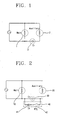
- Figure 1 illustrates a circuit schematically showing a starting unit of a general single-phase induction motor.
- a auxiliary-coil 2 is connected in parallel to a main coil 1 which is connected in series to commercial power, and a capacitor (Cr) 3 for operation for generating a rotating magnetic field is added between the main coil and the auxiliary-coil.
- the power of the capacitor for operation maintains an ON-state and thus a current flows to the auxiliary-coil, whereby the hybrid induction motor is operated as a two-phase induction motor to generate a starting torque.
- the power of the capacitor for operation becomes OFF-state, thereby cutting off a current that is applied to the auxiliary-coil 2.
- a current is applied to the main coil 1, thereby rotating a single-phase induction motor.
- hybrid induction motor is disadvantageous in that a minimum voltage needed for starting the motor is increased, thereby degrading reliability.
- the hybrid induction motor is designed so as to start under a low voltage state, a large rotating torque and a large consumption power are needed in normal operation, thereby degrading operation efficiency.
- an object of the present invention is to provide a driving circuit for improving starting of a hybrid induction motor and its method capable of improving starting efficiency of the motor by reliably starting the motor with minimizing a voltage needed for starting and applying a high starting current, and by operating the motor with a proper current or less after the starting (or in normal operation).
- a driving circuit for improving starting of a hybrid induction motor having a main coil forming a main magnetic field and a auxiliary-coil connected in parallel to the main coil and forming a rotating magnetic field corresponding to a magnetic field generated by the main coil according to claims 1 and 2.
- a driving method for improving starting of a hybrid induction motor having a main coil forming a main magnetic field and a auxiliary-coil connected in parallel to the main coil and forming a rotating magnetic field corresponding to a magnetic field generated by the main coil according to claims 3 to 5.
- Figure 2 is a schematic view showing a driving circuit of a hybrid induction motor.
- a driving circuit of a hybrid induction motor in accordance with the present invention includes a main coil 10 forming a main magnetic field; a auxiliary-coil 20 connected in parallel to the main coil 10 and forming a rotating magnetic field corresponding to a magnetic field generated by the main coil; a capacitor (Cr) 30 for operation electrically connected between the main coil 10 and the auxiliary-coil 20; and a starting and current cutting-off means electrically connected with the capacitor (Cr) 30 for operation, applying a high starting current to a motor in starting, and cutting off the starting current when the motor is operated at a synchronous speed after the starting.
- the starting and current cutting-off means 40 includes a capacitor (Cs) 41 for starting connected in parallel to the capacitor 30 for operation, and applying a high starting current to a motor in starting; and a switch connected in series to the capacitor 41 for starting, turned on in starting, and turned off in normal operation.
- the switch is a resistance device, and, as an example, there may be a PTC thermistor 42 (Positive Temperature Coefficient Thermistor), resistance of which increases to restrain a flow of currents when power is applied thereto.
- a capacitor (Cr) 30 for operation is connected in series to the ends of the main coil 10 and the auxiliary-coil 20, and the capacitor (Cs) 41 for starting and the PTC thermistor 42 which are connected in series to each other are connected in parallel to the capacitor (Cr) 30 for operation.
- a rotor is rotated centering on a rotation shaft by an interaction of magnetic fields formed by the coil.
- a resistance value of the PTC thermistor 42 a current cutting-off means is increased by self heat-generation and its current value is relatively lowered so that the PTC thermistor is off thereby cutting off the power of the capacitor (Cs) 41 for starting.
- the rotor performs operation at a synchronous speed by an interaction between a magnetic field of the main coil 10 and the auxiliary-coil 20 and a magnetic field of a permanent magnet, thereby performing highly effective operation.
- Figure 3 is a flow chart showing operations with respect to a driving method of a hybrid induction motor.
- the driving method of a hybrid induction motor includes a step in which when single-phase commercial power is applied thereto, the PTC thermistor 42 having a low resistance value is turned on to apply a high starting current to (a low-voltage state) a motor by the capacitor (Cs) 41 for starting (SP11, SP12); a step in which a magnet rotor is started by generating a rotating magnetic field by the capacitor (Cs) 41 for starting, and after the magnet rotor rotates at a synchronous speed, a cage rotor is driven (SP13); and a step in which when a certain time elapses (SP14), the PTC thermistor 42 is turned off because self-resistance increases, to apply a low operation current (a normal operation state) to a motor by the capacitor (Cr) 30 for operation, and thus an induction rotor is driven (SP15, SP16).
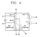
- the main coil is divided into a first main coil 51 and a second main coil 52, and through the starting and current cutting-off means 80, a high starting current is applied to a motor in starting, and a low operation current is applied to the motor in normal operation.
- Figure 4 is a view showing a driving circuit of a hybrid induction motor in accordance with a different embodiment of the present invention.
- a driving motor of a hybrid induction motor in accordance with the present invention includes first and second main coils 51, 52 forming a main magnetic field; a auxiliary-coil 60 connected in parallel to the first and second main coils 51, 52, and forming a rotating magnetic field corresponding to a magnetic field generated by the first and second main coils 51, 52; a capacitor (Cr) 70 for operation electrically connected between the first and second main coils 51, 52 and the auxiliary-coil 60; and a starting and current cutting-off means 80 electrically connected with the capacitor 70 for operation, applying a high starting current to a motor in starting, and cutting off the starting current when the motor is operated at a synchronous speed after the starting.
- first and second main coils 51, 52 forming a main magnetic field
- a auxiliary-coil 60 connected in parallel to the first and second main coils 51, 52, and forming a rotating magnetic field corresponding to a magnetic field generated by the first and second main coils 51, 52
- the starting and current cutting-off means 80 includes a PTC thermistor 82 (Positive Temperature Coefficient Thermistor) connected between a connection point of the first and second main coils 51, 52 and power, turned on in starting, and turned off in normal operation; and an NTC thermistor 81 (Negative Temperature Coefficient Thermistor) connected in series to the first and second main coils 91, 92, turned off in starting, and turned on in normal operation.
- PTC thermistor 82 Physical Temperature Coefficient Thermistor
- NTC thermistor 81 Negative Temperature Coefficient Thermistor
- resistance of a PTC thermistor 82 increases when a temperature is rises, and on the contrary, resistance of an NTC thermistor 82 decreases when a temperature rises. Accordingly, in an initial stage of starting of a motor, when single-phase commercial power is applied to the motor, the PTC thermistor 82 is turned on, and the NTC thermistor 81 is turned off. Therefore, in an initial stage of starting, a magnet rotor is started by generating a rotating magnetic field only with a first main coil and a auxiliary-coil which are connected to the PTC thermistor 82 and after the magnet rotor is rotated at a synchronous speed, a cage rotor is rotated.
- the PTC thermistor 82 is turned off because of a self-resistance value which becomes large, and, on the contrary, the NTC thermistor 81 is turned on because of a self-resistance value which becomes small. That is, under a normal operation state, the NTC thermistor 81 that is connected in series to the first and second main coils 51, 52 is turned on to apply a normal voltage to the motor thereby effectively operating the motor.
- Figure 5 is a flow chart showing operations with respect to a driving method of a hybrid induction motor in accordance with the present invention.
- the driving method of the hybrid induction motor in accordance with the present invention includes a step in which when single-phase commercial power is applied thereto, a PTC thermistor 82 having a low resistance value is turned on and an NTC thermistor 81 having a high resistance value is turned off, to apply a high current (a low-voltage state) to a motor (SP21, SP22); a step in which, a magnet rotor is started by generating a rotating magnetic field by a capacitor (Cr) 81 for operation, and after the magnet rotor is rotated at a synchronous speed, a cage rotor is rotated (SP23); and a step in which after a certain time elapses, the PTC thermistor 82 is turned off because self-resistance becomes large and the NTC thermistor 81 is turned on because self-resistance becomes small, to apply a low operation current (a normal operation state) to a motor, and an induction rotor is
- the present invention is advantageous in that a voltage needed for starting is minimized, at the same time, a motor is reliably started by applying a high starting current, and, after the starting (in normal operation), the motor is operated with a proper current or less, thereby improving starting efficiency of the motor and effectively starting the motor even under a low voltage state.
Landscapes
- Engineering & Computer Science (AREA)
- Power Engineering (AREA)
- Motor And Converter Starters (AREA)
- Control Of Ac Motors In General (AREA)
- Induction Machinery (AREA)
- Permanent Magnet Type Synchronous Machine (AREA)
Claims (5)
- Antriebsschaltung zur Verbesserung des Startens eines hybriden Induktionsmotors, wobei der Motor eine Hauptspule (50) zum Bilden eines magnetischen Hauptfeldes und eine Hilfsspule (60), die parallel zur Hauptspule angeschlossen ist und ein rotierendes Magnetfeld bildet, das einem von der Hauptspule erzeugten Magnetfeld entspricht, umfasst, umfassend:einen Kondensator (Cr) (70) zum elektrischen Betrieb, der zwischen der Hauptspule und der Hilfsspule angeschlossen ist; undein Start- und ein Stromabstellmittel (80), das mit dem Kondensator (Cr) zum Betrieb elektrisch verbunden ist, das einen hohen Startstrom an einen Motor beim Starten anlegt und den Startstrom abstellt, wenn der Motor nach dem Start bei synchroner Geschwindigkeit betrieben wird,wobei die Hauptspule in eine erste (51) und eine zweite (52) Hauptspule unterteilt ist,dadurch gekennzeichnet, dassein hoher Startstrom an den Motor durch das Start- und Stromabstellmittel (80) beim Starten angelegt wird und ein niedriger Betriebsstrom an den Motor im Normalbetrieb angelegt wird und wobei das Start- und Stromabstellmittel einen PTC-Thermistor (82) umfasst, der zwischen einem Verbindungspunkt der ersten und zweiten Hauptspulen und dem Strom angeschlossen ist, und einen NTC-Thermistor (81), der in Serie mit den ersten und zweiten Hauptspulen verbunden ist.
- Antriebsschaltung nach Anspruch 1, wobei der PTC-Thermistor beim Start eingeschaltet ist und im Normalbetrieb ausgeschaltet ist und der NTC-Thermistor beim Start ausgeschaltet ist und im Normalbetrieb eingeschaltet ist.
- Verfahren zur Verbesserung des Startens eines hybriden Induktionsmotors mit einer Hauptspule (50), die ein magnetisches Hauptfeld bildet, und einer Hilfsspule (60), die parallel zur Hauptspule angeschlossen ist und ein rotierendes Magnetfeld bildet, das einem von der Hauptspule erzeugten Magnetfeld entspricht, wobei die Hauptspule in eine erste (51) und eine zweite (52) Hauptspule unterteilt ist,
wobei das Verfahren dadurch gekennzeichnet ist, dass es die folgenden Schritte umfasst:wenn ein einphasiger gewerblicher Strom daran angelegt wird, Anschalten eines PTC-Thermistors (Thermistor mit positivem Temperaturkoeffizienten) mit einem niedrigen Widerstandswert und Abschalten eines NTC-Thermistors mit einem hohen Widerstandswert, um an einen Motor einen hohen Startstrom anzulegen, wobei der PTC-Thermistor (82) zwischen einem Verbindungspunkt der ersten und zweiten Hauptspulen und dem Strom angeschlossen ist, und der NTC-Thermistor (81), der in Serie mit den ersten und zweiten Hauptspulen verbunden ist; Starten eines Magnetrotors durch Erzeugen eines rotierenden Magnetfelds durch einen Kondensator (Cr) zum Betrieb; und Rotieren eines Rotors nachdem der Magnetrotor bei einer synchronen Geschwindigkeit rotiert;und nach Verstreichen einer vorbestimmten Zeit Abschalten des PTC-Thermistors und Einschalten des NTC-Thermistors (Thermistor mit negativem Temperaturkoeffizient), um einen niedrigen Betriebsstrom an den Motor anzulegen, und Betreiben eines Induktionsrotors, wobei der Rotor, der in Rotation versetzt wird, nachdem der Magnetrotor bei einer synchronen Geschwindigkeit rotiert, ein Käfigrotor ist. - Verfahren nach Anspruch 3, wobei der PTC-Thermistor (Thermistor mit positivem Temperaturkoeffizienten) zwischen einem Verbindungspunkt der ersten und zweiten Hauptspulen und dem Strom angeschlossen, beim Starten eingeschaltet und bei Normalbetrieb ausgeschaltet wird.
- Verfahren nach Anspruch 3, wobei der NTC-Thermistor (Thermistor mit negativem Temperaturkoeffizienten) mit der ersten und zweiten Hauptspule und der Energie in Serie geschaltet, bei Starten ausgeschaltet und bei Normalbetrieb eingeschaltet wird.
Applications Claiming Priority (2)
| Application Number | Priority Date | Filing Date | Title |
|---|---|---|---|
| KR2003050728 | 2003-07-23 | ||
| KR1020030050728A KR100823920B1 (ko) | 2003-07-23 | 2003-07-23 | 하이브리드 인덕션 모터의 구동회로 및 방법 |
Publications (3)
| Publication Number | Publication Date |
|---|---|
| EP1501182A2 EP1501182A2 (de) | 2005-01-26 |
| EP1501182A3 EP1501182A3 (de) | 2006-09-06 |
| EP1501182B1 true EP1501182B1 (de) | 2011-09-28 |
Family
ID=33487940
Family Applications (1)
| Application Number | Title | Priority Date | Filing Date |
|---|---|---|---|
| EP04000126A Expired - Lifetime EP1501182B1 (de) | 2003-07-23 | 2004-01-07 | Antriebsschaltung und Verfahren zum Starten hybrider Induktionsmotoren |
Country Status (5)
| Country | Link |
|---|---|
| US (1) | US6930464B2 (de) |
| EP (1) | EP1501182B1 (de) |
| JP (1) | JP2005045992A (de) |
| KR (1) | KR100823920B1 (de) |
| CN (1) | CN1306692C (de) |
Families Citing this family (19)
| Publication number | Priority date | Publication date | Assignee | Title |
|---|---|---|---|---|
| KR20060055046A (ko) * | 2004-11-17 | 2006-05-23 | 삼성전자주식회사 | 단상유도전동기 및 그 소음 저감 방법 |
| CN1294694C (zh) * | 2004-11-24 | 2007-01-10 | 常熟市天银机电有限公司 | 互感式无触点起动器 |
| KR100680212B1 (ko) * | 2005-11-16 | 2007-02-08 | 엘지전자 주식회사 | 전동기 |
| KR101229355B1 (ko) | 2005-12-28 | 2013-02-05 | 엘지전자 주식회사 | 하이브리드 인덕션 모터를 채용한 공기조화기의 팬모터제어장치 및 방법 |
| KR20070071202A (ko) * | 2005-12-29 | 2007-07-04 | 엘지전자 주식회사 | 하이브리드 인덕션 모터의 속도 가변장치 및 방법 |
| KR100757439B1 (ko) * | 2005-12-30 | 2007-09-11 | 엘지전자 주식회사 | 자기 여자 모터 및 그의 착자방법 |
| KR101198235B1 (ko) * | 2006-05-02 | 2012-11-07 | 엘지전자 주식회사 | 모터의 기동 제어 장치 및 방법 |
| EP1997220A1 (de) * | 2006-10-19 | 2008-12-03 | LG Electronics Inc. | Mehrere hybridinduktionsmotoren verwendende antriebsvorrichtung für gebläse |
| KR20080082779A (ko) * | 2007-03-09 | 2008-09-12 | 엘지전자 주식회사 | 모터 |
| KR101322316B1 (ko) * | 2007-05-10 | 2013-10-25 | 엘지전자 주식회사 | 냉장고용 모터의 기동제어장치 및 방법 |
| BRPI0801195A2 (pt) * | 2008-04-14 | 2009-12-29 | Sensata Technologies Ltda | dispositivo protetor de sobrecarga de motor, dispositivo para partida de motor, elemento protetor reserva e processo para obtenção de um elemento protetor reserva |
| KR101006681B1 (ko) * | 2008-07-16 | 2011-01-10 | 엘지전자 주식회사 | 모터 |
| KR101023351B1 (ko) * | 2008-07-16 | 2011-03-18 | 엘지전자 주식회사 | 용량 가변형 압축기 및 이를 구비하는 공기 조화 시스템 |
| KR20100058343A (ko) * | 2008-11-24 | 2010-06-03 | 엘지전자 주식회사 | 단상 유도 모터 |
| US9444306B2 (en) | 2012-05-08 | 2016-09-13 | Remy Technologies, L.L.C. | Variable flux electric starter motor and method of operating the same |
| GB2507268A (en) * | 2012-10-23 | 2014-04-30 | Ford Global Tech Llc | Fast heat steering wheel |
| CN104426429B (zh) * | 2013-08-26 | 2019-10-18 | 森萨塔科技公司 | 正温度系数热敏电阻启动器 |
| CN103580413A (zh) * | 2013-11-01 | 2014-02-12 | 广东美芝制冷设备有限公司 | 单相感应电机、压缩机和空调器 |
| CN104779756B (zh) * | 2015-04-17 | 2017-12-26 | 南通雄亚机电制造有限公司 | 低压单相电机 |
Family Cites Families (19)
| Publication number | Priority date | Publication date | Assignee | Title |
|---|---|---|---|---|
| US3737752A (en) * | 1971-04-09 | 1973-06-05 | Texas Instruments Inc | Motor control system |
| US3725757A (en) * | 1971-05-13 | 1973-04-03 | Thermo Electronics Inc | Starting circuit for permanent split capacitor motor |
| US3916274A (en) * | 1974-07-29 | 1975-10-28 | Alexander J Lewus | Solid state motor starting control |
| US3967172A (en) * | 1975-02-10 | 1976-06-29 | General Electric Company | Control circuit, refrigeration system, and method of controlling speed of an alternating current motor |
| US4066937A (en) * | 1976-01-13 | 1978-01-03 | Lennox Industries, Inc. | Control circuit for a two speed single phase motor |
| DE2821253C3 (de) * | 1978-05-16 | 1981-01-15 | Danfoss A/S, Nordborg (Daenemark) | AnlaDvorrichtung für einen Einphasen-Asynchronmotor |
| US4387330A (en) * | 1980-09-19 | 1983-06-07 | General Electric Company | Balanced single phase alternating current induction motor |
| US4384312A (en) * | 1981-07-29 | 1983-05-17 | Tecumseh Products Company | Line break protection for multispeed motor |
| US5192887A (en) * | 1991-09-23 | 1993-03-09 | Emerson Electric Co. | Starting multi-speed motors at a low speed connection |
| JPH0522915A (ja) * | 1991-07-09 | 1993-01-29 | Matsushita Electric Ind Co Ltd | 自己始動形永久磁石式単相同期電動機 |
| US5212436A (en) * | 1991-12-06 | 1993-05-18 | Texas Instruments Incorporated | Single phase motor start system |
| JPH0638467A (ja) * | 1992-07-09 | 1994-02-10 | Yamada Denki Seizo Kk | 単相誘導電動機の起動装置 |
| JP3272493B2 (ja) * | 1992-12-05 | 2002-04-08 | 山田電機製造株式会社 | 単相誘導電動機の起動装置 |
| DE9421434U1 (de) * | 1994-10-18 | 1996-01-11 | Danfoss Compressors GmbH, 24943 Flensburg | Einphasiger Asynchronmotor |
| US5729416A (en) * | 1995-05-30 | 1998-03-17 | General Electric Company | Motor starter and protector module |
| JP3132992B2 (ja) * | 1995-10-31 | 2001-02-05 | 三菱電機株式会社 | ロータ組立装置 |
| JPH09294387A (ja) * | 1996-04-25 | 1997-11-11 | Murata Mfg Co Ltd | モータ起動用部品 |
| US6271639B1 (en) * | 2000-02-08 | 2001-08-07 | Emerson Electric Co. | Capacitor start single phase induction motor with partial winding starting |
| ES2181598B1 (es) * | 2001-07-10 | 2004-06-01 | Cubigel, S.A. | Un circuito de control para un motor electrico de induccion monofasico. |
-
2003
- 2003-07-23 KR KR1020030050728A patent/KR100823920B1/ko not_active Expired - Fee Related
-
2004
- 2004-01-07 EP EP04000126A patent/EP1501182B1/de not_active Expired - Lifetime
- 2004-01-16 US US10/758,010 patent/US6930464B2/en not_active Expired - Fee Related
- 2004-02-12 CN CNB2004100050115A patent/CN1306692C/zh not_active Expired - Fee Related
- 2004-03-10 JP JP2004067618A patent/JP2005045992A/ja active Pending
Also Published As
| Publication number | Publication date |
|---|---|
| EP1501182A2 (de) | 2005-01-26 |
| CN1306692C (zh) | 2007-03-21 |
| JP2005045992A (ja) | 2005-02-17 |
| KR20050011570A (ko) | 2005-01-29 |
| US6930464B2 (en) | 2005-08-16 |
| CN1578097A (zh) | 2005-02-09 |
| US20050017670A1 (en) | 2005-01-27 |
| KR100823920B1 (ko) | 2008-04-22 |
| EP1501182A3 (de) | 2006-09-06 |
Similar Documents
| Publication | Publication Date | Title |
|---|---|---|
| EP1501182B1 (de) | Antriebsschaltung und Verfahren zum Starten hybrider Induktionsmotoren | |
| CN104242521B (zh) | 一种双模电动发电机 | |
| US8497654B2 (en) | Single phase AC synchronized motor | |
| US7782008B2 (en) | Motor and method for controlling operation of motor | |
| CN104283465A (zh) | 用于监测和控制同步电机的方法和设备 | |
| KR100707424B1 (ko) | 단상 유도 전동기의 기동장치 | |
| JP4595372B2 (ja) | 圧縮機、圧縮機駆動制御装置および圧縮機の駆動制御方法 | |
| EP1605581B1 (de) | Induktionsmotorsteuerung | |
| KR100698218B1 (ko) | 하이브리드 인덕션 모터의 구동회로 | |
| US7084599B2 (en) | Induction motor controller | |
| EP2013962B1 (de) | Startsteuerungsvorrichtung und verfahren für einen motor | |
| US6741061B2 (en) | Efficient stator | |
| KR100511273B1 (ko) | 쉐이딩 코일형 단상유도전동기의 구동장치 | |
| EP1657811B1 (de) | Gerät zur Geschwindigkeits-Steuerung eines Ventilator-Motors einer Klimaanlage mit einem Induktions-Rotor und einem Permanent-Magnet-Rotor | |
| KR100511275B1 (ko) | 쉐이딩 코일형 단상 유도전동기의 구동장치 | |
| JP3659119B2 (ja) | Srモータの制御方法及びsrモータ | |
| JPH01283088A (ja) | 3相直流モータの駆動方法 | |
| JPH06315293A (ja) | 永久磁石形モータの駆動装置 | |
| EP1804369A2 (de) | Vorrichtung und Verfahren zur Drehzahländerung eines Hybridinduktionsmotors | |
| UA52976A (uk) | Пусковий напівпровідниковий пристрій |
Legal Events
| Date | Code | Title | Description |
|---|---|---|---|
| PUAI | Public reference made under article 153(3) epc to a published international application that has entered the european phase |
Free format text: ORIGINAL CODE: 0009012 |
|
| 17P | Request for examination filed |
Effective date: 20040113 |
|
| AK | Designated contracting states |
Kind code of ref document: A2 Designated state(s): AT BE BG CH CY CZ DE DK EE ES FI FR GB GR HU IE IT LI LU MC NL PT RO SE SI SK TR |
|
| AX | Request for extension of the european patent |
Extension state: AL LT LV MK |
|
| PUAL | Search report despatched |
Free format text: ORIGINAL CODE: 0009013 |
|
| AK | Designated contracting states |
Kind code of ref document: A3 Designated state(s): AT BE BG CH CY CZ DE DK EE ES FI FR GB GR HU IE IT LI LU MC NL PT RO SE SI SK TR |
|
| AX | Request for extension of the european patent |
Extension state: AL LT LV MK |
|
| RIC1 | Information provided on ipc code assigned before grant |
Ipc: H02P 1/44 20060101AFI20041103BHEP Ipc: H02P 1/50 20060101ALI20060801BHEP Ipc: H01H 61/00 20060101ALI20060801BHEP Ipc: H02K 21/46 20060101ALI20060801BHEP |
|
| AKX | Designation fees paid |
Designated state(s): DE FR GB IT |
|
| 17Q | First examination report despatched |
Effective date: 20091026 |
|
| GRAP | Despatch of communication of intention to grant a patent |
Free format text: ORIGINAL CODE: EPIDOSNIGR1 |
|
| GRAS | Grant fee paid |
Free format text: ORIGINAL CODE: EPIDOSNIGR3 |
|
| GRAA | (expected) grant |
Free format text: ORIGINAL CODE: 0009210 |
|
| AK | Designated contracting states |
Kind code of ref document: B1 Designated state(s): DE FR GB IT |
|
| REG | Reference to a national code |
Ref country code: GB Ref legal event code: FG4D |
|
| REG | Reference to a national code |
Ref country code: DE Ref legal event code: R096 Ref document number: 602004034500 Country of ref document: DE Effective date: 20111201 |
|
| REG | Reference to a national code |
Ref country code: DE Ref legal event code: R082 Ref document number: 602004034500 Country of ref document: DE Representative=s name: GILLE HRABAL, DE |
|
| PG25 | Lapsed in a contracting state [announced via postgrant information from national office to epo] |
Ref country code: IT Free format text: LAPSE BECAUSE OF FAILURE TO SUBMIT A TRANSLATION OF THE DESCRIPTION OR TO PAY THE FEE WITHIN THE PRESCRIBED TIME-LIMIT Effective date: 20110928 |
|
| PLBE | No opposition filed within time limit |
Free format text: ORIGINAL CODE: 0009261 |
|
| STAA | Information on the status of an ep patent application or granted ep patent |
Free format text: STATUS: NO OPPOSITION FILED WITHIN TIME LIMIT |
|
| 26N | No opposition filed |
Effective date: 20120629 |
|
| GBPC | Gb: european patent ceased through non-payment of renewal fee |
Effective date: 20120107 |
|
| REG | Reference to a national code |
Ref country code: FR Ref legal event code: ST Effective date: 20120928 |
|
| REG | Reference to a national code |
Ref country code: DE Ref legal event code: R097 Ref document number: 602004034500 Country of ref document: DE Effective date: 20120629 |
|
| PG25 | Lapsed in a contracting state [announced via postgrant information from national office to epo] |
Ref country code: GB Free format text: LAPSE BECAUSE OF NON-PAYMENT OF DUE FEES Effective date: 20120107 |
|
| PG25 | Lapsed in a contracting state [announced via postgrant information from national office to epo] |
Ref country code: FR Free format text: LAPSE BECAUSE OF NON-PAYMENT OF DUE FEES Effective date: 20120131 |
|
| PGFP | Annual fee paid to national office [announced via postgrant information from national office to epo] |
Ref country code: DE Payment date: 20121121 Year of fee payment: 10 |
|
| REG | Reference to a national code |
Ref country code: DE Ref legal event code: R119 Ref document number: 602004034500 Country of ref document: DE |
|
| REG | Reference to a national code |
Ref country code: DE Ref legal event code: R119 Ref document number: 602004034500 Country of ref document: DE Effective date: 20140801 |
|
| PG25 | Lapsed in a contracting state [announced via postgrant information from national office to epo] |
Ref country code: DE Free format text: LAPSE BECAUSE OF NON-PAYMENT OF DUE FEES Effective date: 20140801 |