EP1500917A2 - Procedure and device for testing tyres - Google Patents
Procedure and device for testing tyres Download PDFInfo
- Publication number
- EP1500917A2 EP1500917A2 EP04008466A EP04008466A EP1500917A2 EP 1500917 A2 EP1500917 A2 EP 1500917A2 EP 04008466 A EP04008466 A EP 04008466A EP 04008466 A EP04008466 A EP 04008466A EP 1500917 A2 EP1500917 A2 EP 1500917A2
- Authority
- EP
- European Patent Office
- Prior art keywords
- tire
- sensor
- geometric data
- measuring
- testing
- Prior art date
- Legal status (The legal status is an assumption and is not a legal conclusion. Google has not performed a legal analysis and makes no representation as to the accuracy of the status listed.)
- Granted
Links
Images


Classifications
-
- G—PHYSICS
- G01—MEASURING; TESTING
- G01M—TESTING STATIC OR DYNAMIC BALANCE OF MACHINES OR STRUCTURES; TESTING OF STRUCTURES OR APPARATUS, NOT OTHERWISE PROVIDED FOR
- G01M17/00—Testing of vehicles
- G01M17/007—Wheeled or endless-tracked vehicles
- G01M17/02—Tyres
- G01M17/027—Tyres using light, e.g. infrared, ultraviolet or holographic techniques
Definitions
- the invention relates to a method for testing tires and a device for Implementation of such a method.
- Testers for tires are already known. This can be the surface of the tire be examined for defects. This can be done in particular by the irradiation with coherent light, in particular laser light.
- the object of the invention is to provide a method and a device of the type specified Kind of improving.
- the method for testing tires is using a test system, the test system having a memory in which Geometry data of the tire are stored, and at least one measuring head for Examination of the surface of the tire includes.
- the measuring head can be a sensor include.
- the or the measuring heads are taking into account the geometry data the tire is positioned to test the surface of the tire. If the Geometry data of the tire are known, ie in the memory of the test system It is possible to use the measuring head (s) used to test the surface of the tire serve to automatically position. This allows the process be automated to test tires.
- the geometric data of the tire may be the outer diameter of the tire and / or the inner diameter of the tire and / or the width of the tire.
- the geometric data of the tire includes the outer diameter and the inner diameter and the width of the tire.
- the geometric data of the tire may be the inside diameter the tread of the tire and / or the mouth width of the tire and / or the contour of the sidewall of the tire.
- the geometry data of the tire can be entered into the memory, which especially manually. Instead or in addition, the Geometry data of the tire are read into the memory, for example from a database, which can happen especially over the Internet.
- the geometry data of the tire instead or additionally be measured.
- the geometric data of the tire becomes automatic or measured automatically.
- the geometry data of the tire can be measured by a sensor.
- a sensor In particular, it is an outgoing sensor.
- triangulation sensors laser triangulation sensors or ultrasound sensors, but also other sensors or sensors giving away.
- a further advantageous development is characterized in that the sensor is moved or moved relative to the tire.
- a horizontal profile of the tire is measured.
- a vertical profile of the tire can also be measured.
- the surface of the tire is preferably tested interferometrically. Therefor An interferometric measuring head can be used.
- the surface of the tire may be formed by projecting structured light being checked.
- the surface of the tire can also be checked by photogrammetry.
- the surface of the tire is checked by the same sensor is measured by the geometry data of the tire or before have been measured.
- the method can then be carried out particularly advantageously be, in particular by the fact that the same sensor first one or measures several or all geometric data of the tire and then the surface of the tire checks.
- the object underlying the invention is in a device for testing of tires, in particular for carrying out the method according to the invention, achieved in that the device comprises a test system which a memory for storing geometric data of the tire and at least one measuring head for testing the surface of the tire.
- the measuring head can a Sensor for testing the surface of the tire may be present.
- the device comprises a measuring device for measuring the geometry data of the tire.
- the measuring device may include a sensor.
- the measuring device and / or the sensor relative to the tire is movable.
- the measuring device or the sensor is so relative movable to a tire that a horizontal profile of the tire and / or a vertical Profile of the tire are measurable or determinable.
- the test system may include an interferometric probe.
- the senor of the measuring head is the same sensor as the sensor of Measuring device.
- the device includes for testing tires a sensor for measuring the geometry data of the tire and preferably subsequent testing of the surface of the tire is used.
- test objects namely Tires
- the method for testing tires by means of a Test system performed which a memory (not shown in the drawing), are stored in the geometry data of the tire 7, and a measuring head 8 for testing the surface of the tire 7 includes.
- the measuring head 8 is taken into consideration the geometric data of the tire 7 for testing the surface of the Tire 7 positioned.
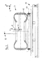
- the geometric data of the tire 7 can be seen from FIG. In the memory are the Outer diameter 1 of the tire, the inner diameter 2 of the tire and the Width 3 of the tire 3 stored. As a result, a model B of the tire 7 can be created which, however, is inadequate in most applications.
- the measuring head 8 comprises a camera C with an optical axis 9 and a Image angle 10.
- the actual field of view of the camera C that is the area of the camera Surface of the tire 7, which at a certain position and orientation of the Camera C in the examination of the surface of the tire 7 can be detected (field of view a single measurement).
- To get out of the position and the angle of view of the camera C is the actual field of view of a single measurement and the number of required ones Measuring positions of the camera used to check the entire surface of the tire required to be able to determine is in many applications
- the knowledge of the inner diameter 4 of the tread of the tire required. The knowledge of the inner diameter 4 of the tread of the tire allows the determination of the object distance, ie the distance of the surface to be tested of the tire to the camera C.
- the jaw width 5 of the tire is of considerable importance, because they the accessibility of the inside to be tested surface or tread of the tire significantly influenced.
- the contour is 6 of the side wall of the tire 7 of considerable importance, in particular for the collision, so to a collision of the measuring head C with the tire 7 to prevent, and the measuring field determination (field of view) in the test the sidewall of the tire 7.
- the mentioned geometry data so the outer diameter 1, the inner diameter 2, the tire width 3, the tread inside diameter 4, the jaw width 5 and / or the sidewall contour 6, can be manually entered and / or read in particular from a database and / or with the help of a barcode.
- this is only possible if the geometry data of the tire is complete are known, but this is not guaranteed in every case.
- Fig. 2 shows a device for testing tires with a tire to be tested 7 in a cross section.
- the device comprises a base 11 with a plurality of rollers 12 which are rotatable about horizontal axes 13 extending in the y-direction are stored, so that the flat tire lying on it 7 in the horizontal x-direction is mobile.
- the device comprises a vertically oriented triangulation sensor H and a horizontally oriented triangulation sensor V. While the tire 7 is moved in the horizontal x-direction, the vertical takes oriented triangulation sensor H has a horizontal profile. A second, vertical Profile is obtained by using the horizontally oriented triangulation sensor V moved by a positioning device A in the vertical direction z becomes.
- the triangulation sensor H can additionally be moved in the horizontal y-direction be (not shown in the drawing).
- the measuring direction of the triangulation sensor H runs in the vertical direction opposite to the z-direction.
- the measuring direction of the triangulation sensor V runs in the horizontal direction opposite to y-direction.
- the triangulation sensors H and V allow all geometry data 1 - 6 are measured.
- the device can be designed in such a way that these measurements are automatic.
- Fig. 2 shows a laser triangulation system.
- the geometry data 1 - 6 also by ultrasonic sensors or other weg sacrificede Sensors, with the help of any existing positioning of the device are moved relative to the tire 7 are measured.
- the surface of the tire 7 can by an interferometric tester being checked.
- the test device can be equipped with any additional hardware required be extended as well as evaluation algorithms for coordinate determination with the same or additional cameras.
- a way to test the surface of the tire 7 is in projecting structured light this surface. By projecting, for example, one or more stripes on the surface of the tire by means of a projection device (e.g. Laser diode with line optics, etc.), whose optical axis to the observation direction assuming a known angle, a pattern can be generated in the image, which are evaluated for distance determination via triangulation calculation can.
- a projection device e.g. Laser diode with line optics, etc.
- Fig. 3 the principle of operation of a light section sensor is shown. Through a Projector 14 is thrown structured light on the projection plane 15, in the the tire 7 is located. The reflected light from there is from a camera 16 recorded and displayed on a monitor 17. There is the curved one See profile 18 of the Tire 7.
- any recognizable pattern e.g. Grids, circles, discs, possibly in different colors and / or intensities
- the evaluation software for lines is the easiest.
- the measuring setup shown in FIG. 3 can be used both for testing the surface of the Tire as well as for the measurement of the geometric data of the tire.
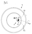
- Fig. 4 shows a tire to be tested 7 in a view from above.
- a laser diode 19 with line optics will be one or more lines 20 on the surface of the tire 7 projected with the shearing camera 21 at a viewing angle 22 to be watched.
- a partial beam be hidden. But this is not absolutely necessary.
- the illumination by the laser diode 19 and the observation by the shearing camera 21 include an angle that allows triangulation through the To determine line coordinates.
- FIG. 5 on the left side, the measuring head positions for measuring the Tire 7 shown.
- the positions to the interferometric Testing the surface of the tire 7 shown where not the overview important, but the high detail resolution.
- the positions according to FIG. 5a and 5b thus serve to measure the geometric data of the tire, the positions in Fig. 5c, d, e and f are for testing the surface of the tire.
- the invention provides a fully automatic tester for tires.
Landscapes
- Physics & Mathematics (AREA)
- General Physics & Mathematics (AREA)
- Length Measuring Devices By Optical Means (AREA)
- Tires In General (AREA)
- Testing Of Balance (AREA)
Abstract
Description
Die Erfindung betrifft ein Verfahren zum Prüfen von Reifen und eine Vorrichtung zur Durchführung eines derartigen Verfahrens.The invention relates to a method for testing tires and a device for Implementation of such a method.
Prüfgeräte für Reifen sind bereits bekannt. Dabei kann die Oberfläche des Reifens auf Fehlstellen untersucht werden. Dies kann insbesondere durch die Bestrahlung mit kohärentem Licht, insbesondere Laserlicht, geschehen.Testers for tires are already known. This can be the surface of the tire be examined for defects. This can be done in particular by the irradiation with coherent light, in particular laser light.
Aufgabe der Erfindung ist es, ein Verfahren und eine Vorrichtung der eingangs angegebenen Art zu verbessern.The object of the invention is to provide a method and a device of the type specified Kind of improving.
Bei einem Verfahren der eingangs angegebenen Art wird diese Aufgabe durch die Merkmale des Anspruchs 1 gelöst. Das Verfahren zum Prüfen von Reifen wird mittels eines Prüfsystems durchgeführt, wobei das Prüfsystem einen Speicher, in dem Geometriedaten des Reifens gespeichert sind, und mindestens einen Messkopf zur Prüfung der Oberfläche des Reifens umfasst. Der Messkopf kann einen Sensor umfassen. Der oder die Messköpfe werden unter Berücksichtigung der Geometriedaten des Reifens zur Prüfung der Oberfläche des Reifens positioniert. Wenn die Geometriedaten des Reifens bekannt sind, also in dem Speicher des Prüfsystems abgelegt sind, ist es möglich, den oder die Messköpfe, die zur Prüfung der Oberfläche des Reifens dienen, automatisch zu positionieren. Hierdurch kann das Verfahren zum Prüfen von Reifen automatisiert werden.In a method of the type specified, this object is achieved by the Characteristics of claim 1 solved. The method for testing tires is using a test system, the test system having a memory in which Geometry data of the tire are stored, and at least one measuring head for Examination of the surface of the tire includes. The measuring head can be a sensor include. The or the measuring heads are taking into account the geometry data the tire is positioned to test the surface of the tire. If the Geometry data of the tire are known, ie in the memory of the test system It is possible to use the measuring head (s) used to test the surface of the tire serve to automatically position. This allows the process be automated to test tires.
Vorteilhafte Weiterbildungen der Erfindung sind in den Unteransprüchen beschrieben.Advantageous developments of the invention are described in the subclaims.
Die Geometriedaten des Reifens können den Außendurchmesser des Reifens und/oder den Innendurchmesser des Reifens und/oder die Breite des Reifens umfassen. Vorzugsweise umfassen die Geometriedaten des Reifens den Außendurchmesser und den Innendurchmesser und die Breite des Reifens.The geometric data of the tire may be the outer diameter of the tire and / or the inner diameter of the tire and / or the width of the tire. Preferably, the geometric data of the tire includes the outer diameter and the inner diameter and the width of the tire.
Stattdessen oder zusätzlich können die Geometriedaten des Reifens den Innendurchmesser der Lauffläche des Reifens und/oder die Maulweite des Reifens und/oder die Kontur der Seitenwand des Reifens umfassen.Instead or in addition, the geometric data of the tire may be the inside diameter the tread of the tire and / or the mouth width of the tire and / or the contour of the sidewall of the tire.
Die Geometriedaten des Reifens können in den Speicher eingegeben werden, was insbesondere manuell geschehen kann. Stattdessen oder zusätzlich können die Geometriedaten des Reifens in den Speicher eingelesen werden, beispielsweise aus einer Datenbank, was insbesondere auch über das Internet geschehen kann.The geometry data of the tire can be entered into the memory, which especially manually. Instead or in addition, the Geometry data of the tire are read into the memory, for example from a database, which can happen especially over the Internet.
Vorteilhaft ist es, wenn die Geometriedaten des Reifens stattdessen oder zusätzlich gemessen werden. Vorzugsweise werden die Geometriedaten des Reifens automatisch bzw. selbsttätig gemessen.It is advantageous if the geometry data of the tire instead or additionally be measured. Preferably, the geometric data of the tire becomes automatic or measured automatically.
Die Geometriedaten des Reifens können durch einen Sensor gemessen werden. Insbesondere handelt es sich dabei um einen weggebenden Sensor. Geeignet sind insbesondere Triangulationssensoren, Laser-Triangulationssensoren oder Ultraschallsensoren, aber auch andere Sensoren bzw. weggebende Sensoren.The geometry data of the tire can be measured by a sensor. In particular, it is an outgoing sensor. Are suitable in particular triangulation sensors, laser triangulation sensors or ultrasound sensors, but also other sensors or sensors giving away.
Eine weitere vorteilhafte Weiterbildung ist dadurch gekennzeichnet, dass der Sensor relativ zum Reifen bewegbar ist bzw. bewegt wird. A further advantageous development is characterized in that the sensor is moved or moved relative to the tire.
Vorzugsweise wird ein horizontales Profil des Reifens gemessen. Stattdessen oder zusätzlich kann allerdings auch ein vertikales Profil des Reifens gemessen werden.Preferably, a horizontal profile of the tire is measured. Instead or In addition, however, a vertical profile of the tire can also be measured.
Die Oberfläche des Reifens wird vorzugsweise interferometrisch geprüft. Hierfür kann ein interferometrischer Messkopf verwendet werden.The surface of the tire is preferably tested interferometrically. Therefor An interferometric measuring head can be used.
Ferner kann die Oberfläche des Reifens durch Projizieren von strukturiertem Licht geprüft werden.Further, the surface of the tire may be formed by projecting structured light being checked.
Die Oberfläche des Reifens kann auch durch Photogrammetrie geprüft werden.The surface of the tire can also be checked by photogrammetry.
Vorteihaft ist es, wenn die Oberfläche des Reifens durch denselben Sensor geprüft wird, durch den die Geometriedaten des Reifens gemessen werden bzw. vorher gemessen worden sind. Das Verfahren kann dann besonders vorteilhaft durchgeführt werden, insbesondere dadurch, dass derselbe Sensor zunächst eine oder mehrere oder alle Geometriedaten des Reifens misst und anschließend die Oberfläche des Reifens prüft.It is advantageous if the surface of the tire is checked by the same sensor is measured by the geometry data of the tire or before have been measured. The method can then be carried out particularly advantageously be, in particular by the fact that the same sensor first one or measures several or all geometric data of the tire and then the surface of the tire checks.
Die der Erfindung zugrundeliegende Aufgabe wird bei einer Vorrichtung zum Prüfen von Reifen, insbesondere zur Durchführung des erfindungsgemäßen Verfahrens, dadurch gelöst, dass die Vorrichtung ein Prüfsystem umfasst, welches einen Speicher zum Speichern von Geometriedaten des Reifens und mindestens einen Messkopf zur Prüfung der Oberfläche des Reifens umfasst. In dem Messkopf kann ein Sensor zur Prüfung der Oberfläche des Reifens vorhanden sein.The object underlying the invention is in a device for testing of tires, in particular for carrying out the method according to the invention, achieved in that the device comprises a test system which a memory for storing geometric data of the tire and at least one measuring head for testing the surface of the tire. In the measuring head can a Sensor for testing the surface of the tire may be present.
Vorteilhafte Weiterbildungen der erfindungsgemäßen Vorrichtung sind Gegenstand der weiteren Unteransprüche.Advantageous developments of the device according to the invention are the subject the further subclaims.
Vorzugsweise umfasst die Vorrichtung eine Messeinrichtung zum Messen der Geometriedaten des Reifens. Die Messeinrichtung kann einen Sensor umfassen. Vorteilhaft ist es, wenn die Messeinrichtung und/oder der Sensor relativ zum Reifen bewegbar ist. Vorzugsweise ist die Messeinrichtung bzw. der Sensor derart relativ zum Reifen bewegbar, dass ein horizontales Profil des Reifens und/oder ein vertikales Profil des Reifens messbar bzw. bestimmbar sind.Preferably, the device comprises a measuring device for measuring the geometry data of the tire. The measuring device may include a sensor. Advantageous it is when the measuring device and / or the sensor relative to the tire is movable. Preferably, the measuring device or the sensor is so relative movable to a tire that a horizontal profile of the tire and / or a vertical Profile of the tire are measurable or determinable.
Das Prüfsystem kann einen interferometrischen Messkopf umfassen.The test system may include an interferometric probe.
Vorzugsweise ist der Sensor des Messkopfes derselbe Sensor wie der Sensor der Messeinrichtung. In diesem Fall umfasst die Vorrichtung zur Prüfung von Reifen einen Sensor, der zum Messen der Geometriedaten des Reifens und zur vorzugsweise anschließenden Prüfung der Oberfläche des Reifens dient.Preferably, the sensor of the measuring head is the same sensor as the sensor of Measuring device. In this case, the device includes for testing tires a sensor for measuring the geometry data of the tire and preferably subsequent testing of the surface of the tire is used.
Ausführungsbeispiele der Erfindung werden nachstehend anhand der beigefügten Zeichnung im einzelnen erläutert. In der Zeichnung zeigt
- Fig. 1
- einen Querschnitt durch einen Reifen in einer schematischen Ansicht,
- Fig. 2
- eine Vorrichtung zum Prüfen von Reifen mit einem zu prüfenden Reifen in einem Querschnitt,
- Fig. 3
- das Funktionsprinzip eines Lichtschnittsensors in einer schematischen perspektivischen Ansicht,
- Fig. 4
- einen zu prüfenden Reifen in einer Ansicht von oben und
- Fig. 5
- mehrere Darstellungen eines Reifens und eines Messkopfs in verschiedenen Stellungen, jeweils im Querschnitt.
- Fig. 1
- a cross section through a tire in a schematic view,
- Fig. 2
- a device for testing tires with a tire to be tested in a cross-section,
- Fig. 3
- the functional principle of a light section sensor in a schematic perspective view,
- Fig. 4
- a tire to be tested in a view from above and
- Fig. 5
- several representations of a tire and a measuring head in different positions, each in cross section.
Für die vollautomatische Prüfung und auch Klassifizierung von Prüfobjekten, nämlich Reifen, ist unter anderem die Kenntnis über die Geometrie des jeweiligen Prüflings bzw. Reifens erforderlich, um den oder die Meßköpfe optimal positionieren zu können, so daß alle relevanten Bereiche erfaßt werden können und gleichzeitig Kollisionen mit dem Reifen vermieden werden können. For the fully automatic testing and classification of test objects, namely Tires, among other things, is the knowledge about the geometry of the respective test object or tire required to optimally position the measuring head or heads can, so that all relevant areas can be detected and simultaneously Collisions with the tire can be avoided.
Um dies zu gewährleisten, wird das Verfahren zum Prüfen von Reifen mittels eines
Prüfsystems durchgeführt, welches einen Speicher (in der Zeichnung nicht dargestellt),
in dem Geometriedaten des Reifens 7 gespeichert sind, und einen Meßkopf
8 zur Prüfung der Oberfläche des Reifens 7 umfaßt. Der Meßkopf 8 wird unter Berücksichtigung
der Geometriedaten des Reifens 7 zur Prüfung der Oberfläche des
Reifens 7 positioniert.To ensure this, the method for testing tires by means of a
Test system performed which a memory (not shown in the drawing),
are stored in the geometry data of the
Die Geometriedaten des Reifens 7 sind aus Fig. 1 ersichtlich. Im Speicher sind der
Außendurchmesser 1 des Reifens, der Innendurchmesser 2 des Reifens und die
Breite 3 des Reifens 3 gespeichert. Hierdurch kann ein Modell B des Reifens 7 erstellt
werden, das allerdings in den meisten Anwendungsfällen unzureichend ist.The geometric data of the
Der Meßkopf 8 umfaßt eine Kamera C mit einer optischen Achse 9 und einem
Bildwinkel 10. Abhängig von der Position der Kamera C und dem Bildwinkel 10 ergibt
sich das tatsächliche Gesichtsfeld der Kamera C, also derjenige Bereich der
Oberfläche des Reifens 7, der bei einer bestimmten Position und Ausrichtung der
Kamera C bei der Prüfung der Oberfläche des Reifens 7 erfaßt werden kann (Gesichtsfeld
einer Einzelmessung). Um aus der Position und dem Bildwinkel der Kamera
C das tatsächliche Gesichtsfeld einer Einzelmessung und die Anzahl der erforderlichen
Meßpositionen der Kamera, die zur Prüfung der gesamten Oberfläche
des Reifens erforderlich sind, bestimmen zu können, ist in vielen Anwendungsfällen
auch die Kenntnis des Innendurchmessers 4 der Lauffläche des Reifens erforderlich.
Die Kenntnis des Innendurchmessers 4 der Lauffläche des Reifens ermöglicht
die Bestimmung des Objektabstandes, also des Abstandes der zu prüfenden Oberfläche
des Reifens zur Kamera C.The measuring
In vielen Anwendungsfällen ist die Maulweite 5 des Reifens von erheblicher Bedeutung,
da sie die Zugänglichkeit der von innen zu prüfenden Oberfläche bzw. Lauffläche
des Reifens maßgeblich beeinflußt. In vielen Anwendungsfällen ist die Kontur
6 der Seitenwand des Reifens 7 von erheblicher Bedeutung, insbesondere für
den Kollisionsschutz, also um eine Kollision des Meßkopfes C mit dem Reifen 7 zu
verhindern, und die Meßfeldbestimmung (Gesichtsfeldbestimmung) bei der Prüfung
der Seitenwand des Reifens 7.In many applications, the jaw width 5 of the tire is of considerable importance,
because they the accessibility of the inside to be tested surface or tread
of the tire significantly influenced. In many cases, the contour is
6 of the side wall of the
Die erwähnten Geometriedaten, also der Außendurchmesser 1, der Innendurchmesser
2, die Reifenbreite 3, der Laufflächen-Innendurchmesser 4, die Maulweite 5
und/oder die Seitenwand-Kontur 6, können manuell eingegeben und/oder eingelesen
werden, insbesondere aus einer Datenbank und/oder mit Hilfe eines Barcodes.
Dies ist allerdings nur dann möglich, wenn die Geometriedaten des Reifens vollständig
bekannt sind, was jedoch nicht in jedem Fall gewährleistet ist.The mentioned geometry data, so the outer diameter 1, the
Im allgemeinen Fall müssen einige oder alle der erwähnten Geometriedaten meßtechnisch ermittelt werden.In the general case, some or all of the geometry data mentioned must be measured be determined.
Fig. 2 zeigt eine Vorrichtung zum Prüfen von Reifen mit einem zu prüfenden Reifen
7 in einem Querschnitt. Die Vorrichtung umfasst ein Untergestell 11 mit einer Vielzahl
von Rollen 12, die um horizontale, in y-Richtung verlaufende Achsen 13 drehbar
gelagert sind, so dass der darauf flach aufliegende Reifen 7 in horizontaler x-Richtung
beweglich ist. Die Vorrichtung umfasst einen vertikal ausgerichteten Triangulationssensor
H und einen horizontal ausgerichteten Triangulationssensor V.
Während der Reifen 7 in horizontaler x-Richtung verfahren wird, nimmt der vertikal
ausgerichtete Triangulationssensor H ein horizontales Profil auf. Ein zweites, vertikales
Profil wird dadurch erhalten, dass der horizontal ausgerichtete Triangulationssensor
V mittels einer Positioniervorrichtung A in vertikaler Richtung z verfahren
wird. Der Triangulationssensor H kann zusätzlich in horizontaler y-Richtung verfahrbar
sein (in der Zeichnung nicht dargestellt). Die Messrichtung des Triangulationssensors
H verläuft in vertikaler Richtung entgegen der z-Richtung. Die Messrichtung
des Triangulationssensors V verläuft in horizontaler Richtung entgegen der
y-Richtung. Durch die Triangulationsssensoren H und V können sämtliche Geometriedaten
1 - 6 gemessen werden. Die Vorrichtung kann derart ausgestaltet sein,
dass diese Messungen automatisch erfolgen. Fig. 2 shows a device for testing tires with a tire to be tested
7 in a cross section. The device comprises a base 11 with a plurality
of
Die Fig. 2 zeigt ein Laser-Triangulationssystem. Stattdessen oder zusätzlich können
die Geometriedaten 1 - 6 auch durch Ultraschallsensoren oder andere weggebende
Sensoren, die mit Hilfe etwaig vorhandener Positioniersysteme der Vorrichtung
relativ zum Reifen 7 bewegt werden, gemessen werden.Fig. 2 shows a laser triangulation system. Instead or in addition
the geometry data 1 - 6 also by ultrasonic sensors or other weggebende
Sensors, with the help of any existing positioning of the device
are moved relative to the
Die Oberfläche des Reifens 7 kann durch eine interferometrische Prüfvorrichtung
geprüft werden. Die Prüfvorrichtung kann um eventuell erforderliche Zusatz-Hardware
erweitert werden sowie um Auswertealgorithmen zur Koordinatenbestimmung
mit derselben oder zusätzlichen Kameras. Eine Möglichkeit zur Prüfung
der Oberfläche des Reifens 7 besteht im Projizieren von strukturiertem Licht auf
diese Oberfläche. Durch Projizieren von beispielsweise einem oder mehreren Streifen
auf die Oberfläche des Reifens mittels einer Projektionseinrichtung (z.B. Projektor,
Laserdiode mit Linienoptik usw.), deren optische Achse zur Beobachtungsrichtung
einen bekannten Winkel einnimmt, kann im Bild ein Muster erzeugt werden,
das zur Abstandsbestimmung über Triangulationsberechnung ausgewertet werden
kann.The surface of the
In Fig. 3 ist das Funktionsprinzip eines Lichtschnittsensors gezeigt. Durch einen
Projektor 14 wird strukturiertes Licht auf die Projektionsebene 15 geworfen, in der
sich der Reifen 7 befindet. Das von dort zurückgestrahlte Licht wird von einer Kamera
16 aufgenommen und auf einem Monitor 17 dargestellt. Dort ist das gekrümmte
Profil 18 des Reifens 7 zu sehen.In Fig. 3, the principle of operation of a light section sensor is shown. Through a
Anstelle von Streifen kann ein beliebiges wiedererkennbares Muster (beispielsweise Gitter, Kreise, Scheiben, eventuell in unterschiedlichen Farben und/oder Intensitäten) projiziert werden. Allerdings ist die Auswerte-Software für Linien am einfachsten.Instead of stripes, any recognizable pattern (e.g. Grids, circles, discs, possibly in different colors and / or intensities) be projected. However, the evaluation software for lines is the easiest.
Zur Beobachtung kann eine zusätzliche Kamera verwendet werden oder aber die Kamera des interferometrischen Prüfsystems. Handelt es sich hierbei um einen Shearing-Aufbau, so werden zwei verschobene Bilder dargestellt. Dies kann durch Ausblenden eines Teilstrahls hardwaretechnisch (beispielsweise mit Hilfe eines Shutters) vermieden werden oder in der Auswertung berücksichtigt werden.For observation, an additional camera can be used or the Camera of the interferometric test system. Is this one? Shearing structure, so two shifted images are displayed. This can be done by Hiding a sub-beam hardware-technically (for example with the help of a Shutters) are avoided or taken into account in the evaluation.
Der in Fig. 3 gezeigte Messaufbau kann sowohl für die Prüfung der Oberfläche des Reifens als auch für die Messung der Geometriedaten des Reifens verwendet werden.The measuring setup shown in FIG. 3 can be used both for testing the surface of the Tire as well as for the measurement of the geometric data of the tire.
Gleiches gilt für ein weiteres mögliches Messverfahren, nämlich die Photogrammetrie.
Wenn man den Reifen 7 mit zwei Kameras betrachtet, deren optische Achsen
einen bekannten Winkel einnehmen, kann man gleiche Orte auf der Oberfläche des
Reifens anhand von per se vorhandenen Oberflächenmerkmalen des Reifens oder
anhand von eigens aufgebrachten photogrammetrischen "Messmarken" in beiden
Bildern identifizieren. Aus den Kamerapositionen und dem eingeschlossenen Winkel
können über eine Triangulationsrechnung die Koordinaten der untersuchten
Prüflinge berechnet werden. Zur Beobachtung können zwei zusätzliche Kameras
eingesetzt werden oder eine zusätzliche Kamera und die Kamera des interferometrischen
Prüfsystems. Handelt es sich hierbei um einen Shearing-Aufbau, werden
zwei verschobene Bilder dargestellt. Dies kann durch Ausblenden eines Teilstrahls
hardwaretechnisch vermieden oder in der Auswertung berücksichtigt werden.The same applies to another possible measuring method, namely photogrammetry.
If you look at the
Fig. 4 zeigt einen zu prüfenden Reifen 7 in einer Ansicht von oben. Durch eine Laserdiode
19 mit Linienoptik werden eine oder mehrere Linien 20 auf die Oberfläche
des Reifens 7 projiziert, die mit der Shearing-Kamera 21 unter einem Bildwinkel 22
beobachtet werden. Dabei kann in der Optik der Shearing-Kamera 21 ein Teilstrahl
ausgeblendet werden. Dies ist aber nicht unbedingt erforderlich.Fig. 4 shows a tire to be tested 7 in a view from above. Through a
Die Beleuchtung durch die Laserdiode 19 und die Beobachtung durch die Shearing-Kamera
21 schließen einen Winkel ein, der es ermöglicht, durch Triangulation die
Linienkoordinaten zu bestimmen. Dazu wird die Anordnung vorher, beispielsweise
mit einem Stufenkörper, kalibriert. The illumination by the
Im Unterschied zur DE 100 09 870 C2 wird dabei nicht derselbe Bildausschnitt wie bei der interferometrischen Prüfung vermessen. Vielmehr werden innerhalb oder außerhalb des Reifens Messkopfpositionen gewählt, unter denen sich die gesuchten Geometriedaten bestimmen lassen.In contrast to DE 100 09 870 C2 is not the same image section as measured during the interferometric test. Rather, within or outside of the tire selected head positions, among which the sought Determine geometry data.
In der Fig. 5 sind auf der linken Seite die Messkopfpositionen zur Vermessung des
Reifens 7 dargestellt. Auf der rechten Seite sind die Positionen zur interferometrischen
Prüfung der Oberfläche des Reifens 7 dargestellt, bei denen nicht der Überblick
wichtig ist, sondern die hohe Detailauflösung. Die Positionen gemäß Fig. 5a
und 5b dienen also zur Messung der Geometriedaten des Reifens, die Positionen
gemäß Fig. 5c, d, e und f dienen zur Prüfung der Oberfläche des Reifens.In FIG. 5, on the left side, the measuring head positions for measuring the
Durch die Erfindung wird ein vollautomatisches Prüfgerät für Reifen geschaffen. Insbesondere ist es möglich, zunächst alle erforderlichen Geometriedaten des Reifens zu messen und anschließend die Oberfläche des Reifens zu prüfen. Dies kann mit ein und demselben Sensor bzw. Messkopf geschehen.The invention provides a fully automatic tester for tires. In particular, it is possible first of all all required geometric data of the tire to measure and then to test the surface of the tire. This can done with one and the same sensor or measuring head.
Claims (21)
Applications Claiming Priority (2)
| Application Number | Priority Date | Filing Date | Title |
|---|---|---|---|
| DE10333802A DE10333802B4 (en) | 2003-07-24 | 2003-07-24 | Method and device for testing tires |
| DE10333802 | 2003-07-24 |
Publications (3)
| Publication Number | Publication Date |
|---|---|
| EP1500917A2 true EP1500917A2 (en) | 2005-01-26 |
| EP1500917A3 EP1500917A3 (en) | 2006-05-10 |
| EP1500917B1 EP1500917B1 (en) | 2010-02-24 |
Family
ID=33483054
Family Applications (1)
| Application Number | Title | Priority Date | Filing Date |
|---|---|---|---|
| EP04008466A Expired - Lifetime EP1500917B1 (en) | 2003-07-24 | 2004-04-07 | Procedure and device for testing tyres |
Country Status (3)
| Country | Link |
|---|---|
| US (1) | US7360410B2 (en) |
| EP (1) | EP1500917B1 (en) |
| DE (2) | DE10333802B4 (en) |
Cited By (8)
| Publication number | Priority date | Publication date | Assignee | Title |
|---|---|---|---|---|
| WO2007110412A1 (en) * | 2006-03-27 | 2007-10-04 | Maehner Bernward | Apparatus and method for testing a tyre |
| WO2007110414A1 (en) * | 2006-03-27 | 2007-10-04 | Maehner Bernward | Device and method for inspecting a tyre, in particular using an interferometric measuring method |
| WO2007113231A1 (en) * | 2006-03-31 | 2007-10-11 | Maehner Bernhard | Device and method for checking a tyre in particular by means of an interferometric measuring method |
| EP2026056A2 (en) | 2007-08-13 | 2009-02-18 | Steinbichler Optotechnik Gmbh | Tyre testing device |
| EP2105701A1 (en) * | 2008-03-25 | 2009-09-30 | Steinbichler Optotechnik Gmbh | Method and device for determining the 3D coordinates of an object |
| CN101245987B (en) * | 2007-02-16 | 2011-03-23 | 伯尼沃德·梅尼尔 | Device and method for testing tires, in particular by means of interferometry |
| FR2981450A1 (en) * | 2011-10-17 | 2013-04-19 | Eads Europ Aeronautic Defence | SYSTEM AND METHOD FOR CONTROLLING THE QUALITY OF AN OBJECT |
| EP2141476A3 (en) * | 2008-07-03 | 2014-06-25 | Hankook Tire Co., Ltd | System and method for analyzing tire uniformity |
Families Citing this family (19)
| Publication number | Priority date | Publication date | Assignee | Title |
|---|---|---|---|---|
| AU1823799A (en) | 1997-12-29 | 1999-07-19 | Ameritech Corporation | System and method for home automation and security |
| US8111904B2 (en) | 2005-10-07 | 2012-02-07 | Cognex Technology And Investment Corp. | Methods and apparatus for practical 3D vision system |
| DE102006061003B4 (en) | 2006-12-22 | 2009-03-26 | Mähner, Bernward | Device for testing a test object, in particular a tire, by means of a non-destructive measuring method |
| US8126260B2 (en) * | 2007-05-29 | 2012-02-28 | Cognex Corporation | System and method for locating a three-dimensional object using machine vision |
| US9734419B1 (en) | 2008-12-30 | 2017-08-15 | Cognex Corporation | System and method for validating camera calibration in a vision system |
| EP2211161B1 (en) * | 2009-01-22 | 2012-07-11 | Snap-on Equipment Srl a unico socio | Wheel diagnosis system |
| JP5318657B2 (en) * | 2009-05-13 | 2013-10-16 | 株式会社ブリヂストン | Tire inspection equipment |
| US9533418B2 (en) | 2009-05-29 | 2017-01-03 | Cognex Corporation | Methods and apparatus for practical 3D vision system |
| EP2353890A1 (en) * | 2010-01-29 | 2011-08-10 | Snap-on Equipment Srl a unico socio | Apparatus and method of determing geometrical dimensions of a tyre with optical sensors |
| FR2957417B1 (en) * | 2010-03-15 | 2013-01-04 | Michelin Soc Tech | HOLDING DEVICE FOR VISUAL INSPECTION OF A TIRE |
| US9393694B2 (en) | 2010-05-14 | 2016-07-19 | Cognex Corporation | System and method for robust calibration between a machine vision system and a robot |
| US9124873B2 (en) | 2010-12-08 | 2015-09-01 | Cognex Corporation | System and method for finding correspondence between cameras in a three-dimensional vision system |
| DE102013010402A1 (en) * | 2013-06-21 | 2014-12-24 | Steinbichler Optotechnik Gmbh | Tire tester, tire tester and tire testing method |
| CN106353341A (en) * | 2016-10-22 | 2017-01-25 | 钟贵洪 | Tire detecting instrument |
| JP6740093B2 (en) * | 2016-11-11 | 2020-08-12 | Toyo Tire株式会社 | Tire inspection device and inspection method |
| DE102018001255A1 (en) | 2018-02-18 | 2019-08-22 | Bernward Mähner | Method and device for investigating rotationally symmetrical test objects |
| EP4416459B1 (en) | 2021-10-12 | 2024-12-04 | Dengler, Stefan | Method for testing tyres |
| DE102022126613A1 (en) | 2022-10-12 | 2024-04-18 | Stefan Dengler | Procedure for testing tires |
| WO2025024919A1 (en) * | 2023-07-28 | 2025-02-06 | 3Dm Devices Inc. | Apparatus for tire scanning and methods of using same |
Citations (1)
| Publication number | Priority date | Publication date | Assignee | Title |
|---|---|---|---|---|
| EP1284409A1 (en) | 2001-08-16 | 2003-02-19 | Bernward Mähner | Method and apparatus for the inspection of the deformation of objects |
Family Cites Families (17)
| Publication number | Priority date | Publication date | Assignee | Title |
|---|---|---|---|---|
| US3918816A (en) * | 1974-04-22 | 1975-11-11 | Autech Corp | Tire inspection apparatus |
| US4311044A (en) * | 1980-02-25 | 1982-01-19 | The B. F. Goodrich Company | Tire sidewall bump/depression detection system |
| US4526030A (en) * | 1983-05-18 | 1985-07-02 | Vecera Jr Guy L | Multi-functional tire testing tool |
| US4631831A (en) * | 1986-01-31 | 1986-12-30 | Bandag Licensing Corporation | Tread depth probe and computer |
| US5249460A (en) * | 1991-12-16 | 1993-10-05 | Bridgestone Corporation | Method and apparatus for measuring irregular tread wear |
| US5245867A (en) * | 1991-12-16 | 1993-09-21 | Bridgestone Corporation | Method and apparatus for measuring tire parameters |
| DE4232201A1 (en) * | 1992-09-25 | 1994-03-31 | Sp Reifenwerke Gmbh | Vehicle tyre cross-section measuring device - uses two optical or ultrasonic reflection measuring devices respectively facing inner and outer surface of tyre |
| IT1273333B (en) * | 1994-02-24 | 1997-07-08 | Pirelli | METHOD AND EQUIPMENT FOR THE TRACKING OF A FOOTPRINT DRAWING ON THE TIRE BAND OF A TIRE |
| US6034676A (en) * | 1995-04-11 | 2000-03-07 | Data View, Inc. | System and method for measuring and processing tire depth data |
| JPH09251011A (en) * | 1996-03-14 | 1997-09-22 | Kawasaki Steel Corp | Rotary tire type ultrasonic probe |
| US5789668A (en) * | 1996-08-15 | 1998-08-04 | Bridgestone/Firestone, Inc. | Apparatus and related methods for obtaining tire profiles including the tread and both sidewalls |
| DE59805066D1 (en) * | 1997-06-10 | 2002-09-12 | Beissbarth Gmbh | Tire inspection method and device |
| DE19911913A1 (en) * | 1999-03-17 | 2000-09-21 | Beissbarth Gmbh | Tire inspection method and device |
| EP1043578B1 (en) * | 1999-04-09 | 2004-10-13 | Steinbichler Optotechnik Gmbh | Optical testing apparatus for tires |
| EP1099947A3 (en) * | 1999-11-12 | 2003-01-29 | Laser Technology Inc. | Apparatus and method for performing optical tyre testing |
| DE10036010A1 (en) * | 2000-07-25 | 2002-02-07 | Thyssenkrupp Ag | Control of ply joint or splice location during tire building involves camera detection of strip-shaped laser light areas projected onto materials at the joint |
| DE10319099B4 (en) * | 2003-04-28 | 2005-09-08 | Steinbichler Optotechnik Gmbh | Method for interference measurement of an object, in particular a tire |
-
2003
- 2003-07-24 DE DE10333802A patent/DE10333802B4/en not_active Revoked
-
2004
- 2004-04-07 DE DE502004010797T patent/DE502004010797D1/en not_active Expired - Lifetime
- 2004-04-07 EP EP04008466A patent/EP1500917B1/en not_active Expired - Lifetime
- 2004-07-26 US US10/899,415 patent/US7360410B2/en not_active Expired - Lifetime
Patent Citations (1)
| Publication number | Priority date | Publication date | Assignee | Title |
|---|---|---|---|---|
| EP1284409A1 (en) | 2001-08-16 | 2003-02-19 | Bernward Mähner | Method and apparatus for the inspection of the deformation of objects |
Non-Patent Citations (1)
| Title |
|---|
| "Intact 1200 from Steinbichler", RETREADING BUSINESS, no. 13, February 2000 (2000-02-01), pages 16, XP003011471 |
Cited By (13)
| Publication number | Priority date | Publication date | Assignee | Title |
|---|---|---|---|---|
| WO2007110412A1 (en) * | 2006-03-27 | 2007-10-04 | Maehner Bernward | Apparatus and method for testing a tyre |
| WO2007110414A1 (en) * | 2006-03-27 | 2007-10-04 | Maehner Bernward | Device and method for inspecting a tyre, in particular using an interferometric measuring method |
| US8074506B2 (en) | 2006-03-27 | 2011-12-13 | Bernward Maehner | Apparatus and method for testing a tire |
| WO2007113231A1 (en) * | 2006-03-31 | 2007-10-11 | Maehner Bernhard | Device and method for checking a tyre in particular by means of an interferometric measuring method |
| CN101245987B (en) * | 2007-02-16 | 2011-03-23 | 伯尼沃德·梅尼尔 | Device and method for testing tires, in particular by means of interferometry |
| US7810388B2 (en) | 2007-08-13 | 2010-10-12 | Steinbichler Optotechnik Gmbh | Tire testing facility |
| DE102007038176A1 (en) * | 2007-08-13 | 2009-02-19 | Steinbichler Optotechnik Gmbh | tire testing |
| EP2026056A2 (en) | 2007-08-13 | 2009-02-18 | Steinbichler Optotechnik Gmbh | Tyre testing device |
| EP2549258A1 (en) | 2007-08-13 | 2013-01-23 | Steinbichler Optotechnik GmbH | Tyre testing device |
| EP2105701A1 (en) * | 2008-03-25 | 2009-09-30 | Steinbichler Optotechnik Gmbh | Method and device for determining the 3D coordinates of an object |
| EP2141476A3 (en) * | 2008-07-03 | 2014-06-25 | Hankook Tire Co., Ltd | System and method for analyzing tire uniformity |
| FR2981450A1 (en) * | 2011-10-17 | 2013-04-19 | Eads Europ Aeronautic Defence | SYSTEM AND METHOD FOR CONTROLLING THE QUALITY OF AN OBJECT |
| WO2013057115A1 (en) * | 2011-10-17 | 2013-04-25 | European Aeronautic Defence And Space Company Eads France | System and method for controlling the quality of an object |
Also Published As
| Publication number | Publication date |
|---|---|
| US7360410B2 (en) | 2008-04-22 |
| EP1500917B1 (en) | 2010-02-24 |
| DE10333802A1 (en) | 2005-02-24 |
| US20050109091A1 (en) | 2005-05-26 |
| EP1500917A3 (en) | 2006-05-10 |
| DE502004010797D1 (en) | 2010-04-08 |
| DE10333802B4 (en) | 2005-09-08 |
Similar Documents
| Publication | Publication Date | Title |
|---|---|---|
| EP1500917B1 (en) | Procedure and device for testing tyres | |
| DE102007009040C5 (en) | Device and method for testing a tire, in particular by means of an interferometric measuring method | |
| EP2732236B1 (en) | Optical device and method for inspecting tires | |
| DE69330466T2 (en) | METHOD AND DEVICE FOR DETERMINING THE ALIGNMENT OF MOTOR VEHICLE WHEELS | |
| DE69828673T2 (en) | Evaluation device for the tire configuration and tire classification method | |
| DE102010015566B4 (en) | Method and system for measuring reflective surfaces | |
| EP2002235B1 (en) | Device and method for checking a tyre in particular by means of an interferometric measuring method | |
| WO1999004248A1 (en) | Method for the automatic recognition of surface defects in body shells and device for carrying out said method | |
| EP1969309A1 (en) | Method for optically measuring a chassis | |
| EP2263062B1 (en) | Device and method for measuring the topography of surfaces of articles | |
| DE10127304C2 (en) | Method and device for determining the three-dimensional contour of a reflecting surface of an object | |
| EP1837623B1 (en) | Method and device for recording the surface form of a partially reflective surface | |
| DE102017001750A1 (en) | Inner wall measuring instrument and offset amount calculation method | |
| EP2064518B1 (en) | Method for determining distances for measuring the chassis of a motor vehicle | |
| EP3545259B1 (en) | Method and apparatus for examining rotationally symmetric test objects | |
| DE112015002961T5 (en) | A method of manufacturing a component and manufacturing apparatus using such a method, and volume measuring methods | |
| DE102004033526A1 (en) | Analysis of at least partly reflecting surfaces involves varying relative orientation/position of object, pattern generation device and/or image receiver(s) for image reflected at surface, to obtain surface, especially geometry, information | |
| DE102006048726A1 (en) | Method for measuring the wheel or axle geometry of a vehicle | |
| EP3803351A1 (en) | Device for surface inspection of a motor vehicle and method for same | |
| DE102020132736B4 (en) | Mobile analysis system for heterogeneous rock and/or soil samples | |
| DE102012020719A1 (en) | System for measuring motor car before and after collision test, has multi-measuring chambers including photogrammetry measuring device for optical single point measurement and optical scanning device for surface measurement | |
| DE10019387C2 (en) | Tire inspection method and apparatus | |
| DE102005048134B3 (en) | Welding component, e.g. motor vehicle axle, measuring and/or testing device, has support columns arranged on base plate, clamping device provided at free ends of columns to clamp component, and arbor displaceable relative to clamping device | |
| DE10143812A1 (en) | Device for determination of the spatial position of two bodies relative to each other in either orthogonal or angular coordinate systems based on use of simple and low-cost reflective optical components | |
| DE102010029627A1 (en) | Device for determining structure of reflecting surface area of e.g. concave object in motor car, has measuring unit that measures pattern surface, where spatial coordinate of pixel of surface is determined for each image capturing point |
Legal Events
| Date | Code | Title | Description |
|---|---|---|---|
| PUAI | Public reference made under article 153(3) epc to a published international application that has entered the european phase |
Free format text: ORIGINAL CODE: 0009012 |
|
| AK | Designated contracting states |
Kind code of ref document: A2 Designated state(s): AT BE BG CH CY CZ DE DK EE ES FI FR GB GR HU IE IT LI LU MC NL PL PT RO SE SI SK TR |
|
| AX | Request for extension of the european patent |
Extension state: AL HR LT LV MK |
|
| PUAL | Search report despatched |
Free format text: ORIGINAL CODE: 0009013 |
|
| AK | Designated contracting states |
Kind code of ref document: A3 Designated state(s): AT BE BG CH CY CZ DE DK EE ES FI FR GB GR HU IE IT LI LU MC NL PL PT RO SE SI SK TR |
|
| AX | Request for extension of the european patent |
Extension state: AL HR LT LV MK |
|
| RIC1 | Information provided on ipc code assigned before grant |
Ipc: G01B 11/25 20060101ALI20060322BHEP Ipc: G01B 11/08 20060101ALI20060322BHEP Ipc: G01B 11/24 20060101ALI20060322BHEP Ipc: G01M 17/02 20060101AFI20041102BHEP |
|
| 17P | Request for examination filed |
Effective date: 20060705 |
|
| 17Q | First examination report despatched |
Effective date: 20061030 |
|
| AKX | Designation fees paid |
Designated state(s): DE FR IT |
|
| TPAC | Observations filed by third parties |
Free format text: ORIGINAL CODE: EPIDOSNTIPA |
|
| GRAP | Despatch of communication of intention to grant a patent |
Free format text: ORIGINAL CODE: EPIDOSNIGR1 |
|
| GRAS | Grant fee paid |
Free format text: ORIGINAL CODE: EPIDOSNIGR3 |
|
| GRAA | (expected) grant |
Free format text: ORIGINAL CODE: 0009210 |
|
| AK | Designated contracting states |
Kind code of ref document: B1 Designated state(s): DE FR IT |
|
| REF | Corresponds to: |
Ref document number: 502004010797 Country of ref document: DE Date of ref document: 20100408 Kind code of ref document: P |
|
| PLBE | No opposition filed within time limit |
Free format text: ORIGINAL CODE: 0009261 |
|
| STAA | Information on the status of an ep patent application or granted ep patent |
Free format text: STATUS: NO OPPOSITION FILED WITHIN TIME LIMIT |
|
| 26N | No opposition filed |
Effective date: 20101125 |
|
| PGFP | Annual fee paid to national office [announced via postgrant information from national office to epo] |
Ref country code: DE Payment date: 20150429 Year of fee payment: 12 |
|
| REG | Reference to a national code |
Ref country code: DE Ref legal event code: R231 Ref document number: 502004010797 Country of ref document: DE |
|
| PG25 | Lapsed in a contracting state [announced via postgrant information from national office to epo] |
Ref country code: DE Free format text: LAPSE BECAUSE OF THE APPLICANT RENOUNCES Effective date: 20151123 |
|
| REG | Reference to a national code |
Ref country code: FR Ref legal event code: PLFP Year of fee payment: 13 |
|
| REG | Reference to a national code |
Ref country code: FR Ref legal event code: PLFP Year of fee payment: 14 |
|
| REG | Reference to a national code |
Ref country code: FR Ref legal event code: PLFP Year of fee payment: 15 |
|
| PGFP | Annual fee paid to national office [announced via postgrant information from national office to epo] |
Ref country code: IT Payment date: 20230426 Year of fee payment: 20 Ref country code: FR Payment date: 20230420 Year of fee payment: 20 |