EP3545259B1 - Method and apparatus for examining rotationally symmetric test objects - Google Patents
Method and apparatus for examining rotationally symmetric test objects Download PDFInfo
- Publication number
- EP3545259B1 EP3545259B1 EP19704777.2A EP19704777A EP3545259B1 EP 3545259 B1 EP3545259 B1 EP 3545259B1 EP 19704777 A EP19704777 A EP 19704777A EP 3545259 B1 EP3545259 B1 EP 3545259B1
- Authority
- EP
- European Patent Office
- Prior art keywords
- test object
- test
- axial section
- image
- images
- Prior art date
- Legal status (The legal status is an assumption and is not a legal conclusion. Google has not performed a legal analysis and makes no representation as to the accuracy of the status listed.)
- Active
Links
- 238000012360 testing method Methods 0.000 title claims description 113
- 238000000034 method Methods 0.000 title claims description 46
- 238000012545 processing Methods 0.000 claims description 14
- 238000001514 detection method Methods 0.000 claims description 9
- 238000006073 displacement reaction Methods 0.000 claims description 6
- 230000007547 defect Effects 0.000 claims description 5
- 239000011324 bead Substances 0.000 description 12
- 238000005259 measurement Methods 0.000 description 11
- 230000010363 phase shift Effects 0.000 description 6
- 230000009466 transformation Effects 0.000 description 5
- 230000003287 optical effect Effects 0.000 description 4
- 238000011156 evaluation Methods 0.000 description 3
- 238000007689 inspection Methods 0.000 description 3
- 239000000523 sample Substances 0.000 description 3
- 238000010008 shearing Methods 0.000 description 3
- 238000011161 development Methods 0.000 description 2
- 230000018109 developmental process Effects 0.000 description 2
- 238000003384 imaging method Methods 0.000 description 2
- 230000008030 elimination Effects 0.000 description 1
- 238000003379 elimination reaction Methods 0.000 description 1
- 238000005305 interferometry Methods 0.000 description 1
- 230000004807 localization Effects 0.000 description 1
- 238000000691 measurement method Methods 0.000 description 1
- 238000011158 quantitative evaluation Methods 0.000 description 1
- 230000003068 static effect Effects 0.000 description 1
- 238000010998 test method Methods 0.000 description 1
- 238000011144 upstream manufacturing Methods 0.000 description 1
Images


Classifications
-
- G—PHYSICS
- G01—MEASURING; TESTING
- G01B—MEASURING LENGTH, THICKNESS OR SIMILAR LINEAR DIMENSIONS; MEASURING ANGLES; MEASURING AREAS; MEASURING IRREGULARITIES OF SURFACES OR CONTOURS
- G01B11/00—Measuring arrangements characterised by the use of optical techniques
- G01B11/16—Measuring arrangements characterised by the use of optical techniques for measuring the deformation in a solid, e.g. optical strain gauge
- G01B11/161—Measuring arrangements characterised by the use of optical techniques for measuring the deformation in a solid, e.g. optical strain gauge by interferometric means
- G01B11/162—Measuring arrangements characterised by the use of optical techniques for measuring the deformation in a solid, e.g. optical strain gauge by interferometric means by speckle- or shearing interferometry
-
- G—PHYSICS
- G01—MEASURING; TESTING
- G01B—MEASURING LENGTH, THICKNESS OR SIMILAR LINEAR DIMENSIONS; MEASURING ANGLES; MEASURING AREAS; MEASURING IRREGULARITIES OF SURFACES OR CONTOURS
- G01B11/00—Measuring arrangements characterised by the use of optical techniques
- G01B11/24—Measuring arrangements characterised by the use of optical techniques for measuring contours or curvatures
Definitions
- interferometric measurement methods such as the ESPI (Electronic Speckle Pattern Interferometry) or the shearing method
- ESPI Electro Speckle Pattern Interferometry
- shearing method is used for the areal determination of displacements or strains of a test object with a diffusely scattering surface.
- Which method can be used for a given test object depends on the size to be measured and the required measuring range.
- Another aspect in the selection of the measuring method are the costs for the measuring system.
- the shearing method has clear advantages over other interferometric measuring methods, since it makes do with simple laser diodes because of the short required coherence length.
- phase shift method W. Ost, "Digital Processing and Evaluation of Interference Images", chap. 6 Academy publishing house ISBN 3-05-501294-1 ).
- This phase images are generated, which assign each pixel a certain phase angle.
- the phase shift method offers the advantage of a normalized result image whose gray values in the entire image are proportional to the determined phase angle. The readability of such result images is clearly improved over simple interference fringe images.
- Differometry only subtracts speckle patterns from different stress states. It can only be distinguished between those points where the deformation is zero and those where the deformation is not zero. A quantitative evaluation is not possible. Likewise, no phase shift method is feasible due to the lack of interferometer.
- the interferometric measurement must often take place successively or simultaneously in several sections.
- a typical application of this kind is for example the interferometric testing of tires.
- DE 42 31 578 C2 a method for the determination of deformations on test objects, wherein the embodiment shows that thought was given in particular to the sector-by-sector testing of tires.
- the patent US 5,786,533 proposes a method for the targeted localization of defects in tires, especially in the belt area. Again, the arrangement of measuring head and test object shown allows an evaluation of the entire belt area only if it is tested in several sectors.
- the positioning of the measuring head relative to the test object can be done by geometrical measurement of the test object and subsequent calculation of a suitable position for the measuring head. This is for example in the patent DE 103 33 802 B4 described.
- the result images of the individual sections are displayed individually or next to one another on a vision system.
- the object of the new method and the new device is therefore to show a cost-effective alternative, namely for the applications in which the test object consists of an at least approximately rotationally symmetrical body, such as a vehicle or aircraft tires.
- the rotationally symmetric test object which may be in particular a vehicle or aircraft tire, is exposed to various loads for testing.
- This load can be generated for example by raising and lowering the ambient pressure.
- the object surface is in spatially offset sections with one or more measuring heads, each with a camera examined with image sensor.
- the measuring heads can in particular be interferometric measuring heads.
- the image sensor consists for example of a CCD or a CMOS area sensor.
- the spatial offset can be generated, for example, by rotating the test object about its axis of rotation relative to the measuring head or the measuring heads.
- images of the test object are detected by the image sensor and supplied to an image processing system for further processing.
- an image processing system for further processing.
- the image processing system calculates the displacement or the stress / strain state of the test object representing result images.
- the result images may be, for example, phase difference images generated by means of a phase shift method.
- the spatial position of the individual examined sections is determined relative to one another.
- at least one axial section of the test object is determined.
- the axial section-in the sense of the invention consists of points of intersection or intersection of the surface of the test object with a sectional plane in which the axis of rotation of the test object lies.
- the axial section can also contain calculated interpolation points or interpolation points with coordinates whose components are calculated to one part measured to the other part.
- the axial section may contain only a few individual measured points.
- the measuring points can also come from different axial sections whose sectional planes are rotated against each other.
- the interpolation points can be connected, for example, to a contour line for purposes of illustration.
- the axial section can advantageously be determined from the outside of the test object and / or from the inside of the test object.
- the measurement of outside and inside is particularly advantageous if the test object in relation to its size has considerable wall thickness or significant fluctuations in the wall thickness.
- the determined axial section is used according to the invention in order to determine in each case the correct position and orientation of the measuring head relative to the axial section for the examined sections of the object surface.
- the orientation is the position of the optical axis of the camera of the measuring head for axial section. Calculations necessary for this are advantageously carried out in the sectional plane of the axial section.
- the rotational position of the measuring head in the circumferential direction of the test object is determined relative to the test object.
- the spatial position and orientation of the measuring head to the test object for each tested section is determined therefrom.
- the spatial positions of the sections imaged in the result images are calculated according to the invention from the object surface relative to the test object.
- the spatial coordinates are also calculated for the points imaged in the result images from the surface of the test object and assigned to the corresponding pixels. The calculation of the spatial coordinates is advantageously carried out assuming the rotational symmetry of the test object.
- a projection of a rotational body defined by the axial section onto the image plane can be calculated for each image of the test object, from which in turn the spatial coordinates of the imaged points on the surface of the test object can be calculated.
- the rotation body is calculated from selected interpolation points of an axial section in order to simplify the calculation. It eliminates the effort to record for each detected pixel of the test object and its spatial coordinates by measurement.
- the calculation of the spatial coordinates of imaged object points requires a calibration of the beam path of the camera.
- the spatial position of an imaged point from the surface of the test object can be calculated on the basis of its image coordinates, ie its position in the image plane.
- the image coordinates usually consist of the number of the image line and the number of the image column.
- An essential aspect of the inventive method steps described above is to avoid the metrological detection of the spatial coordinates of the surface points imaged in the individual result images, in which the measurement is replaced by a calculation.
- the sector boundaries in the result images are determined and pixels outside the sectors are eliminated, i. not used.
- isoclines are suitable as sector boundaries.
- the location of the sector boundaries corresponds to the number of test sectors required for gap-free scanning of the test object in the circumferential direction or used for generating the result images.
- the boundary lines of the object surface are determined in the individual result images and pixels lying outside the boundary lines are eliminated.
- boundary lines are above all viewing limits into consideration.
- lying outside the object pixels or non-interest areas of the object can be hidden.
- the calculated boundary lines are subsequently transferred into a common coordinate system. If the positions of the sector boundaries correspond to the number of check sectors, then the sector boundaries will come from circumferentially consecutive result images to each other and within the respective sector boundaries image data can be attached directly to each other.
- a common coordinate system which may be, for example, a polar coordinate system
- the pixels each lying in a result image within the boundary lines are transmitted by interpolation into the common coordinate system.
- This interpolation can also take place solely on the basis of the image coordinates of both the boundary lines used and the pixels to be transmitted. In this procedure, the interpolation takes place in the image plane, wherein the curvature of the object is neglected orthogonal to the image plane.
- An essential advantage of interpolation in the image plane using boundary lines is that only one interpolation point in the axial section must be present for the calculation of the boundary lines.
- the pixels of different sections or result images of the test object have been transferred to a common coordinate system, they are advantageously displayed in an overall view.
- This overall view is advantageously a raster graphic, ie a digital image with a large number of discrete pixels.
- the overall view may be a computational processing of the object surface.
- the settlement can be - such as the development of the surface of a tire - be distorted.
- the readability is still significantly improved for the viewer compared to the usual single image display.
- a three-dimensional model of the test object can also be calculated and displayed, on the surface of which the pixels of the result images are positioned and displayed on the basis of their calculated spatial coordinates.
- defects or gaps can arise during the subsequent creation of a raster graphic. These are advantageously closed by interpolation from the values of the surrounding surface points.
- the automatic, computer-aided identification of features, in particular defects of the test object is performed in the overall view.
- the determined axial section is further used to calculate the probe positions in performing the test. Further, it is advantageously used to calculate the required number of sectors required for gapless inspection of the object in the circumferential direction.
- FIG. 1 shows a test system that corresponds to the device according to the invention and is suitable for carrying out the method according to the invention.
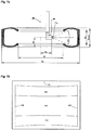
- a system for testing tires 10 has a measuring head 20 with a camera 21 for taking pictures.
- the measuring head 20 can via a positioning device 24 and 23 are moved horizontally and vertically relative to the test object 101.
- the horizontal positioning device 24 is fixedly connected to the base frame 11, so that the measuring head 20 is horizontally and vertically movable relative to the test object.
- the inclination of the optical axis 22 of the camera 21 with respect to the test object 101 can be changed via a pivot axis 25.
- the test system also has a turntable 12 for rotating the tire 101 relative to the measuring head 20. This allows testing of the tire 101 over its entire circumference.
- the turntable 12 has a conveyor belt 13 which allows the infeed and outfeed of the tires to be tested (101, 102).
- a distance sensor 30 with a vertically downwardly directed laser beam 31 allows the measurement of the distance from the sensor 30 to the point of impact of the laser beam 31 on a surface, in particular the surface of the tire to be tested.
- the sensor 30 is fixedly connected to the base frame 11.
- the sensor 30 is aligned centrally to the width of the conveyor belt 13, so that when conveying a tire, the laser beam is at least approximately in a plane defined by the axis of rotation of the tire and conveying direction plane.
- a delivery module 40 is connected upstream of this.
- the conveyor module 40 has a motor-driven conveyor belt 41, which has an incremental encoder (encoder) 42 for measuring the distance traveled by the tire on the conveyor module path, which may be part of the drive of the conveyor belt 41.
- an incremental encoder encoder
- PLC programmable logic controller
- the tire 102 is moved by the conveyor module 40 by means of the conveyor belt 41 in the direction of the conveyor belt 13 on the turntable 12. At this time, the tire 102 passes under the distance sensor 30, so that the sensor 30 scans the upper side wall 113 and the upper bead 114 of the tire 102.
- the encoder 42 provides the distance traveled of the tire 102 proportional number of pulses. These are counted by the programmable logic controller 50 and detected simultaneously with each pulse, the instantaneous reading of the sensor 30.
- the result of the measurement of the axial section is exemplary in the FIG. 3 shown. From the measurement result directly results the values for the outer diameter D a , the inner diameter D i of the tire 102 and the total width B max .
- the inner diameter D i corresponds to the rim hole diameter of the tire.
- the points P a and P i can be used to calculate viewing limits.
- the FIG. 4 shows a distance sensor 32 which is mounted below the measuring head 20 and detects when entering the measuring head 20 in the tire 102 through the rim hole an axial section of the tire. At this time, the laser beam 33 of the sensor 32 first scans the upper side wall 113 of the tire 102, then the inside of the bead 114, and finally the tread of the tire from the inside.
- FIG. 5 shows graphically the means of in FIG. 4 shown sensor 32 detected axial section.
- the solid line is the actual metrologically detected contour line, whereas the dashed portions of the contour line are calculated by reflection at the tire center plane RME and the axis of rotation A r .
- the values for the inner bead spacing B wi and the outer diameter D ai are determined on the inside of the tire.
- FIG. 6 shows the combination of the axial sections of the FIG. 3 and the FIG. 5 , Opposite the FIG. 3
- the half of the axial section lying below the tire center plane was generated from the outside of the tire by mathematically mirroring the upper half of the outer axial section at the tire center plane.
- the axial section resulting from the combination of the axial sections results in a more accurate model of the test object. Thereby, the calculation of the space coordinates of imaged points of the surface of the test object can be performed with greater accuracy.
- the position of the test object in the field of view of the camera is calculated.
- the result is for the positioning and orientation of the camera out of the Figure 7a in the FIG. 7b shown graphically.
- the field of view of the camera is limited by the boundary line 130.
- the partial areas overhead shoulder 110, tread 111 and underlying shoulder 112 are shown with their boundary lines within the viewing window.
- the boundary lines are calculated by computational projection of the rotational body defined by the axial section into the image plane. Further, the left sector boundary 120 and the right sector boundary 121 are drawn.
- the position of the sector boundaries (120, 121) is determined by the width of the camera viewport, the position and orientation of the camera relative to the axial section, and the number of inspection sectors.
- the calculated Sector boundaries (120, 121) are used in particular for the elimination of overlapping areas in the overall representation.
- FIG. 8a shows the conditions with a vertical view of the camera on the outside of the tire sidewall. This is also a typical arrangement for testing tires. In this positioning and alignment of the camera, the sidewall 113 and the bead 114 of the tire are inspected from the outside.
- the FIG. 8b shows the calculated position of the tire 102 in the field of view of the camera.
- the field of view is bounded by the line 130.
- the sidewall of the tire is divided into the sidewall region 113 (outside the rim) and the bead region 114.
- the boundary lines in the radial direction are the outer boundary line 122 and the inner boundary line 123.
- the outer boundary line 122 can be generated by rotation of the point P a about the rotation axis A r and the inner boundary line 123 by rotation of the point P i about the axis of rotation A r ( FIG. FIG. 3 and FIG. 8a ).
- the calculated boundary lines of the sector in the circumferential direction are again the line 120 for the left sector boundary and the line 121 for the right sector boundary.
- the offset is determined sector by sector via suitable image processing functions and eliminated.
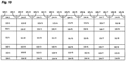
- FIG. 9 shows a schematic single image representation of all sectors of a tire test in three passes.
- the top 2 rows show the 8 result images from the 1st sidewall of the tire according to an arrangement FIG. 8a in the middle two rows, the 8 result images from the inside of the tread according to an arrangement Figure 7a and the lower two rows reproduce the 8 result images from the 2nd sidewall of the tire according to an arrangement FIG. 8a ,
- the tire must be turned so that the lower sidewall of the tire is accessible for testing.
- a Different number of sectors may be required to consistently check the sidewall of the tire and the tread of the tire.
- FIG. 10 shows the according to the new method from those in FIG. 9 overall view calculated. All of the tire areas within the sector boundaries shown in the individual images are located in a positionally correct position relative to one another. Outside the sector and tire areas lying pixels are eliminated, so that there is a clear view of the entire tire surface.
- the right sector boundaries (121/1 ... 121/8) coincide respectively with the left sector boundary (120/1 ... 120/8) of the subsequent sector in the circumferential direction of the tire.
- the sector boundary 121/8 is advantageously connected to the sector boundary 120/1. In digital image processing, this can be realized via a ring buffer.
- FIGS. 11a to 11c Show the compilation of all the result images of a bead to bead testing on a truck tire.
- the result images from the outside of the first side wall are in FIG. 11a shown.
- the result images from the inside of the tread are in FIG. 11b shown.
- the result images from the outside of the second side wall are in FIG FIG. 11c shown.
- the pictures of the tread in FIG. 11b show belt edge solutions in the upper and lower tire shoulders which extend over several sectors.
- FIG. 12 the pixels of the test object of all result images are the FIGS. 11a to 11c transferred to the process of the invention in a representation. Overlap areas and areas outside the tire are completely eliminated. This can be seen in particular in the side wall regions 113, 115 and the bead regions 114, 116.
- the belt edge solutions in the shoulder regions 110 and 112 are joined together across sectors and thus recognizable in their true extent in the circumferential direction. Well recognizable now is the local expansion of the belt edge solutions into the sidewall areas.
Description
Es ist bekannt, dass zur flächenhaften Bestimmung von Verschiebungen oder Dehnungen eines Prüfobjektes mit diffus streuender Oberfläche interferometrische Messverfahren, wie das ESPI- (Electronic Speckle Pattern Interferometry) oder das Shearing Verfahren zum Einsatz kommen. Welches Verfahren für ein gegebenes Prüfobjekt angewendet werden kann, hängt von der zu messenden Größe und dem erforderlichen Messbereich ab. Ein weiterer Aspekt bei der Auswahl des Messverfahrens sind aber auch die Kosten für das Messsystem. Hier hat beispielsweise das Shearing Verfahren gegenüber anderen interferometrischen Messverfahren klare Vorteile, da es wegen der kurzen erforderlichen Kohärenzlänge mit einfachen Laserdioden auskommt. Ferner ist es, wie beispielsweise die Patentschrift
Bei den genannten interferometrischen Prüfverfahren werden bei statischer Prüfung üblicherweise zwei Zustände des Prüfobjektes verglichen, indem das Objekt in zwei unterschiedlichen Belastungszuständen aufgenommen wird und die Interferogramme der beiden Zustände subtrahiert werden. Hierdurch ergibt sich ein Differenzinterferogramm, welches die Verschiebung oder die Dehnung des Objektes zwischen den beiden Zuständen in Form von Interferenzlinien darstellt. Wird der Messkopf mit einer Phasenschiebeeinheit ausgerüstet, so kann eine erweiterte Auswertung nach dem Prinzip des Phasenshiftverfahrens durchgeführt werden (
Bei der Differometrie werden lediglich Specklemuster von verschiedenen Belastungszuständen subtrahiert. Es kann nur zwischen solchen Punkten unterschieden werden, bei denen die Verformung Null ist, und solchen, bei denen die Verformung ungleich Null ist. Eine quantitative Auswertung ist nicht möglich. Ebenso ist aufgrund des fehlenden Interferometers kein Phasenshiftverfahren durchführbar.Differometry only subtracts speckle patterns from different stress states. It can only be distinguished between those points where the deformation is zero and those where the deformation is not zero. A quantitative evaluation is not possible. Likewise, no phase shift method is feasible due to the lack of interferometer.
Je nach Form und Größe des Prüfobjektes muss die interferometrische Messung häufig nacheinander oder gleichzeitig in mehreren Abschnitten erfolgen. Eine typische Anwendung dieser Art ist beispielsweise die interferometrische Prüfung von Reifen. So beschreibt die Patentschrift
Die Positionierung des Messkopfes relativ zum Prüfobjekt kann durch geometrische Vermessung des Prüfobjekts und anschließende Berechnung einer geeigneten Position für den Messkopf erfolgen. Dies ist beispielsweise in der Patentschrift
Ein Verfahren zur Korrektur von Formdaten eines ringförmigen, rotierenden Objekts, beispielsweise eines Reifens, und eine Vorrichtung zur Inspektion eines solchen Objekts beschreibt
Üblicherweise werden bei abschnittsweise prüfenden Messsystemen die Ergebnisbilder von den einzelnen Abschnitten einzeln oder nebeneinander angeordnet auf einem Sichtsystem angezeigt.Normally, in the case of measurement systems that test in sections, the result images of the individual sections are displayed individually or next to one another on a vision system.
Die Offenlegungsschrift
In der Praxis hat es sich allerdings gezeigt, dass der apparative Aufwand zur flächenhaften topometrischen Erfassung der Objektoberfläche nach obenstehendem Verfahren, insbesondere bei Verwendung von mehreren Prüfköpfen, erhebliche Kosten verursacht und darüber hinaus die zur Konturerfassung erforderliche zusätzliche Rechenzeit im industriellen Einsatz nicht immer akzeptabel ist.In practice, however, it has been shown that the expenditure on equipment for the areal topometric detection of the object surface according to the above method, especially when using multiple probes, causes considerable costs and beyond the time required for contour detection additional computing time in industrial use is not always acceptable.
Aufgabe des neuen Verfahrens und der neuen Vorrichtung ist es daher, eine kostengünstige Alternative aufzuzeigen, und zwar für die Anwendungsfälle, bei denen das Prüfobjekt aus einem zumindest näherungsweise rotationssymmetrischen Körper, so zum Beispiel einem Fahrzeug- oder Flugzeugreifen, besteht.The object of the new method and the new device is therefore to show a cost-effective alternative, namely for the applications in which the test object consists of an at least approximately rotationally symmetrical body, such as a vehicle or aircraft tires.
Diese Aufgabe wird durch das in Patentanspruch 1 angegebene Verfahren und die in Patentanspruch 14 angegebene Vorrichtung (Prüfsystem) gelöst.This object is achieved by the method specified in claim 1 and the device specified in claim 14 (test system).
Vorteilhafte Weiterbildungen sind in den jeweiligen Unteransprüchen angegeben.Advantageous developments are specified in the respective subclaims.
Erfindungsgemäß wird das rotationssymmetrische Prüfobjekt, das insbesondere ein Fahrzeug- oder Flugzeugreifen sein kann, zur Prüfung verschiedenen Belastungen ausgesetzt. Diese Belastung kann beispielsweise durch Anheben und Absenken des Umgebungsdruckes erzeugt werden. Zur Untersuchung des Prüfobjektes über seinen gesamten Umfang wird die Objektoberfläche in räumlich versetzten Abschnitten mit ein oder mehreren Messköpfen mit jeweils einer Kamera mit Bildsensor untersucht. Die Messköpfe können insbesondere interferometrische Messköpfe sein. Der Bildsensor besteht beispielsweise aus einem CCD oder einem CMOS Flächensensor. Der räumliche Versatz kann dabei beispielsweise durch Drehen des Prüfobjektes um seine Rotationsachse relativ zum Messkopf bzw. den Messköpfen erzeugt werden.According to the invention, the rotationally symmetric test object, which may be in particular a vehicle or aircraft tire, is exposed to various loads for testing. This load can be generated for example by raising and lowering the ambient pressure. To examine the test object over its entire circumference, the object surface is in spatially offset sections with one or more measuring heads, each with a camera examined with image sensor. The measuring heads can in particular be interferometric measuring heads. The image sensor consists for example of a CCD or a CMOS area sensor. The spatial offset can be generated, for example, by rotating the test object about its axis of rotation relative to the measuring head or the measuring heads.
Zur flächigen Erfassung der durch die verschiedenen Belastungen hervorgerufenen Verschiebungen oder Dehnungen der Objektoberfläche werden Abbildungen vom Prüfobjekt von dem Bildsensor erfasst und diese zur Weiterverarbeitung einem Bildverarbeitungssystem zugeführt. Hierdurch ist beispielsweise die Anwendung eines Phasenshiftverfahrens möglich.For the areal registration of the displacements or expansions of the object surface caused by the various loads, images of the test object are detected by the image sensor and supplied to an image processing system for further processing. As a result, for example, the application of a phase shift method is possible.
Aus den erzeugten Abbildungen werden vom Bildverarbeitungssystem die Verschiebung oder den Spannungs-/ Dehnungszustand des Prüfobjektes darstellende Ergebnisbilder berechnet. Die Ergebnisbilder können beispielsweise mittels eines Phasenshiftverfahrens erzeugte Phasendifferenzbilder sein. Erfindungsgemäß wird die räumliche Position der einzelnen untersuchten Abschnitte zueinander ermittelt. Hierzu wird wenigstens ein Axialschnitt von dem Prüfobjekt ermittelt. Der Axialschnitt - im Sinne der Erfindung -besteht aus Schnitt- bzw. Stützpunkten von der Oberfläche des Prüfobjekts mit einer Schnittebene, in der die Rotationsachse des Prüfobjekts liegt. Der Axialschnitt kann neben gemessenen Stützpunkten auch berechnete Stützpunkte enthalten oder Stützpunkte mit Koordinaten deren Komponenten zu einem Teil gemessen zum anderen Teil berechnet sind. Der Axialschnitt kann nur wenige einzelne gemessene Stützpunkte enthalten. Die Messpunkte können auch aus verschiedenen Axialschnitten stammen, deren Schnittebenen gegeneinander gedreht sind. Die Stützpunkte können beispielsweise zu Darstellungszwecken zu einer Konturlinie verbunden werden.From the generated images, the image processing system calculates the displacement or the stress / strain state of the test object representing result images. The result images may be, for example, phase difference images generated by means of a phase shift method. According to the invention, the spatial position of the individual examined sections is determined relative to one another. For this purpose, at least one axial section of the test object is determined. The axial section-in the sense of the invention-consists of points of intersection or intersection of the surface of the test object with a sectional plane in which the axis of rotation of the test object lies. In addition to measured interpolation points, the axial section can also contain calculated interpolation points or interpolation points with coordinates whose components are calculated to one part measured to the other part. The axial section may contain only a few individual measured points. The measuring points can also come from different axial sections whose sectional planes are rotated against each other. The interpolation points can be connected, for example, to a contour line for purposes of illustration.
Der Axialschnitt kann mit Vorteil von der Außenseite des Prüfobjektes ermittelt werden und/oder von der Innenseite des Prüfobjektes. Die Vermessung von Außen- und Innenseite ist insbesondere dann von Vorteil, falls das Prüfobjekt im Verhältnis zu seiner Größe über erhebliche Wandstärken oder erhebliche Schwankungen in der Wandstärke verfügt. Besitzt das Prüfobjekt neben der Rotationssymmetrie weitere Symmetrieeigenschaften, so z.B. eine Spiegelsymmetrie im Axialschnitt, so genügt es, eine Hälfte des Axialschnitts messtechnisch zu erfassen und die andere Hälfte durch Spiegelung an der Symmetrieachse zu berechnen.The axial section can advantageously be determined from the outside of the test object and / or from the inside of the test object. The measurement of outside and inside is particularly advantageous if the test object in relation to its size has considerable wall thickness or significant fluctuations in the wall thickness. Does the test object in addition to the rotational symmetry further symmetry properties, such as a mirror symmetry in axial section, it is sufficient to detect one half of the axial section by measurement and to calculate the other half by mirroring on the axis of symmetry.
Der ermittelte Axialschnitt wird erfindungsgemäß dazu verwendet, um für die untersuchten Abschnitte der Objektoberfläche jeweils die zutreffende Position und Ausrichtung des Messkopfes relativ zu dem Axialschnitt zu ermitteln. Die Ausrichtung ist dabei die Lage der optischen Achse der Kamera des Messkopfes zum Axialschnitt. Hierzu notwendige Berechnungen werden mit Vorteil in der Schnittebene des Axialschnittes durchgeführt. Ferner wird die Drehstellung des Messkopfes in Umfangsrichtung des Prüfobjekts relativ zum Prüfobjekt ermittelt. In einem weiteren Verfahrensschritt wird daraus die räumliche Position und Ausrichtung des Messkopfes zum Prüfobjekt für jeden geprüften Abschnitt ermittelt.The determined axial section is used according to the invention in order to determine in each case the correct position and orientation of the measuring head relative to the axial section for the examined sections of the object surface. The orientation is the position of the optical axis of the camera of the measuring head for axial section. Calculations necessary for this are advantageously carried out in the sectional plane of the axial section. Furthermore, the rotational position of the measuring head in the circumferential direction of the test object is determined relative to the test object. In a further method step, the spatial position and orientation of the measuring head to the test object for each tested section is determined therefrom.
Aus den ermittelten Positionen und Drehstellungen werden erfindungsgemäß die räumlichen Positionen der in den Ergebnisbildern jeweils abgebildeten Abschnitte von der Objektoberfläche relativ zum Prüfobjekt berechnet.From the determined positions and rotational positions, the spatial positions of the sections imaged in the result images are calculated according to the invention from the object surface relative to the test object.
Aufgrund der Ermittlung der Position und der Ausrichtung des Messkopfes relativ zum Axialschnitt erhält man rechnerisch zumindest näherungsweise die tatsächliche Position des Messkopfes relativ zum Prüfobjekt für jeden geprüften Abschnitt. Es entfällt damit der Aufwand, jeden erfassten Abschnitt des Prüfobjekts auch topometrisch zu vermessen. Gemäß einem weiteren Aspekt der Erfindung werden darüber hinaus für die in den Ergebnisbildern abgebildeten Punkte von der Oberfläche des Prüfobjektes die Raumkoordinaten berechnet und den entsprechenden Bildpunkten zugeordnet. Die Berechnung der Raumkoordinaten erfolgt mit Vorteil unter Annahme der Rotationssymmetrie des Prüfobjektes. Dadurch kann eine Projektion eines durch den Axialschnitt festgelegten Rotationskörpers auf die Bildebene für jede Abbildung des Prüfobjektes berechnet werden, woraus wiederum die Raumkoordinaten der abgebildeten Punkte von der Oberfläche des Prüfobjektes berechenbar sind. Mit Vorteil wird der Rotationskörper aus ausgewählten Stützpunkten eines Axialschnitts berechnet, um die Berechnung zu vereinfachen. Es entfällt damit der Aufwand, für jeden erfassten Bildpunkt des Prüfobjektes auch dessen Raumkoordinaten messtechnisch zu erfassen. Gemäß einem weiteren Aspekt der Erfindung werden die das Prüfobjekt abbildenden Bildpunkte in ein gemeinsames Objektkoordinatensystem übertragen. Die Berechnung der Raumkoordinaten von abgebildeten Objektpunkten erfordert eine Kalibrierung des Strahlengangs der Kamera. Ist dabei eine Korrektur der optischen Verzerrung innerhalb eines abgebildeten Abschnitts nicht erforderlich, so genügt es, die Öffnungswinkel der abbildenden Optik in horizontaler und vertikaler Bildrichtung zu ermitteln. Durch diese Kalibrierung ist in Kombination mit den vorgenannten Verfahrensschritten die räumliche Position eines abgebildeten Punktes von der Oberfläche des Prüfobjektes anhand seiner Bildkoordinaten berechenbar, d.h. seiner Position in der Abbildungsebene. Bei der digitalen Bildverarbeitung mit diskreten Bildpunkten bestehen die Bildkoordinaten üblicherweise aus Nummer der Bildzeile und Nummer der Bildspalte.Due to the determination of the position and the orientation of the measuring head relative to the axial section, one obtains, mathematically, at least approximately the actual position of the measuring head relative to the test object for each section tested. This eliminates the effort to survey each detected section of the test object also topometrically. In accordance with a further aspect of the invention, the spatial coordinates are also calculated for the points imaged in the result images from the surface of the test object and assigned to the corresponding pixels. The calculation of the spatial coordinates is advantageously carried out assuming the rotational symmetry of the test object. As a result, a projection of a rotational body defined by the axial section onto the image plane can be calculated for each image of the test object, from which in turn the spatial coordinates of the imaged points on the surface of the test object can be calculated. Advantageously, the rotation body is calculated from selected interpolation points of an axial section in order to simplify the calculation. It eliminates the effort to record for each detected pixel of the test object and its spatial coordinates by measurement. According to another Aspect of the invention are transmitted to the test object imaging pixels in a common object coordinate system. The calculation of the spatial coordinates of imaged object points requires a calibration of the beam path of the camera. If it is not necessary to correct the optical distortion within an imaged section, it is sufficient to determine the aperture angles of the imaging optics in the horizontal and vertical image direction. By means of this calibration, in combination with the aforementioned method steps, the spatial position of an imaged point from the surface of the test object can be calculated on the basis of its image coordinates, ie its position in the image plane. In digital image processing with discrete pixels, the image coordinates usually consist of the number of the image line and the number of the image column.
Wesentlicher Aspekt der obenstehend beschriebenen erfindungsgemäßen Verfahrensschritte ist es, die messtechnische Erfassung der Raumkoordinaten der in den einzelnen Ergebnisbildern abgebildeten Oberflächenpunkte zu vermeiden, in dem die Messung durch eine Berechnung ersetzt wird.An essential aspect of the inventive method steps described above is to avoid the metrological detection of the spatial coordinates of the surface points imaged in the individual result images, in which the measurement is replaced by a calculation.
Gemäß einem Aspekt der Erfindung werden die Sektorengrenzen in den Ergebnisbildern ermittelt und außerhalb der Sektoren liegende Bildpunkte eliminiert, d.h. nicht weiterverwendet. Als Sektorengrenzen sind insbesondere Isoklinen geeignet. Hierdurch werden einander überlagernde Bildpunkte verhindert. Vorteilhafterweise entspricht die Lage der Sektorengrenzen der Anzahl der Prüfsektoren, die zur lückenlosen Abtastung des Prüfobjektes in Umfangsrichtung erforderlich ist bzw. zur Erstellung der Ergebnisbilder verwendet worden ist.According to one aspect of the invention, the sector boundaries in the result images are determined and pixels outside the sectors are eliminated, i. not used. In particular, isoclines are suitable as sector boundaries. As a result, superimposed pixels are prevented. Advantageously, the location of the sector boundaries corresponds to the number of test sectors required for gap-free scanning of the test object in the circumferential direction or used for generating the result images.
Gemäß einem weiteren Aspekt der Erfindung werden die Grenzlinien der Objektoberfläche in den einzelnen Ergebnisbildern ermittelt und außerhalb der Grenzlinien liegende Bildpunkte eliminiert. Als Grenzlinien kommen hier vor allem Sichtgrenzen in Betracht. Hierdurch können außerhalb des Objektes liegende Bildpunkte oder nicht interessierende Bereiche des Objektes ausgeblendet werden.According to a further aspect of the invention, the boundary lines of the object surface are determined in the individual result images and pixels lying outside the boundary lines are eliminated. As boundary lines here are above all viewing limits into consideration. As a result, lying outside the object pixels or non-interest areas of the object can be hidden.
Mit Vorteil werden anschließend die berechneten Grenzlinien in ein gemeinsames Koordinatensystem übertragen. Entsprechen die Positionen der Sektorengrenzen der Anzahl der Prüfsektoren, dann stoßen die Sektorengrenzen von in Umfangsrichtung aufeinanderfolgenden Ergebnisbildern aneinander an und die innerhalb der jeweiligen Sektorengrenzen liegenden Bilddaten können direkt aneinander angehängt werden. Zur Übertragung der Bildpunkte in ein gemeinsames Koordinatensystem, das beispielsweise ein Polarkoordinatensystem sein kann, werden die jeweils in einem Ergebnisbild innerhalb der Grenzlinien liegenden Bildpunkte durch eine Interpolation in das gemeinsame Koordinatensystem übertragen. Diese Interpolation kann auch allein anhand der Bildkoordinaten sowohl der verwendeten Grenzlinien als auch der zu übertragenden Bildpunkte erfolgen. Bei dieser Vorgehensweise erfolgt die Interpolation in der Bildebene, wobei die Krümmung des Objektes orthogonal zur Bildebene vernachlässigt wird. Es hat sich allerdings in der Praxis gezeigt, dass diese Vereinfachung bei der Darstellung von Prüfergebnissen noch ausreichend genau ist. Wesentlicher Vorteil der Interpolation in der Bildebene unter Verwendung von Grenzlinien ist es, dass zur Berechnung der Grenzlinien nur jeweils ein Stützpunkt in dem Axialschnitt vorhanden sein muss.Advantageously, the calculated boundary lines are subsequently transferred into a common coordinate system. If the positions of the sector boundaries correspond to the number of check sectors, then the sector boundaries will come from circumferentially consecutive result images to each other and within the respective sector boundaries image data can be attached directly to each other. For transferring the pixels into a common coordinate system, which may be, for example, a polar coordinate system, the pixels each lying in a result image within the boundary lines are transmitted by interpolation into the common coordinate system. This interpolation can also take place solely on the basis of the image coordinates of both the boundary lines used and the pixels to be transmitted. In this procedure, the interpolation takes place in the image plane, wherein the curvature of the object is neglected orthogonal to the image plane. However, it has been shown in practice that this simplification in the presentation of test results is still sufficiently accurate. An essential advantage of interpolation in the image plane using boundary lines is that only one interpolation point in the axial section must be present for the calculation of the boundary lines.
Sind die Bildpunkte von verschiedenen Abschnitten bzw. Ergebnisbildern des Prüfobjektes in ein gemeinsames Koordinatensystem übertragen worden, so werden diese mit Vorteil in einer Gesamtansicht dargestellt. Bei dieser Gesamtansicht handelt es sich mit Vorteil um eine Rastergrafik, das heißt ein digitales Bild mit einer Vielzahl von diskreten Bildpunkten. Die Gesamtansicht kann gemäß einem Aspekt der Erfindung eine rechnerische Abwicklung der Objektoberfläche sein. Die Abwicklung kann - wie beispielsweise die Abwicklung der Oberfläche eines Reifens - verzerrt sein. Die Lesbarkeit ist für den Betrachter gegenüber der üblichen Einzelbilddarstellung dennoch deutlich verbessert. Mit Vorteil kann auch ein dreidimensionales Modell des Prüfobjektes berechnet und angezeigt werden, auf dessen Oberfläche die Bildpunkte der Ergebnisbilder anhand ihrer berechneten Raumkoordinaten positioniert und dargestellt werden.If the pixels of different sections or result images of the test object have been transferred to a common coordinate system, they are advantageously displayed in an overall view. This overall view is advantageously a raster graphic, ie a digital image with a large number of discrete pixels. The overall view, according to one aspect of the invention, may be a computational processing of the object surface. The settlement can be - such as the development of the surface of a tire - be distorted. The readability is still significantly improved for the viewer compared to the usual single image display. Advantageously, a three-dimensional model of the test object can also be calculated and displayed, on the surface of which the pixels of the result images are positioned and displayed on the basis of their calculated spatial coordinates.
Bei der Übertragung der Bildpunkte in ein gemeinsames Koordinatensystem können beim anschließenden Erstellen einer Rastergrafik Fehlstellen bzw. Lücken entstehen. Diese werden mit Vorteil durch eine Interpolation aus den Werten der umliegenden Oberflächenpunkte geschlossen.When transferring the pixels into a common coordinate system, defects or gaps can arise during the subsequent creation of a raster graphic. These are advantageously closed by interpolation from the values of the surrounding surface points.
Mit Vorteil wird die automatische, rechnergestützte Identifizierung von Merkmalen insbesondere Defekten des Prüfobjektes in der Gesamtansicht durchgeführt.Advantageously, the automatic, computer-aided identification of features, in particular defects of the test object, is performed in the overall view.
Hierdurch ist die Berechnung der korrekten Größe von Merkmalen insbesondere in Umfangsrichtung des Prüfobjektes mit großer Genauigkeit möglich.In this way, the calculation of the correct size of features, in particular in the circumferential direction of the test object, is possible with great accuracy.
Der ermittelte Axialschnitt wird gemäß einem Aspekt der Erfindung ferner zur Berechnung der Messkopfpositionen bei der Durchführung der Prüfung herangezogen. Ferner wird er mit Vorteil zur Berechnung der erforderlichen Anzahl von Sektoren herangezogen, die zur lückenlosen Prüfung des Objektes in Umfangsrichtung erforderlich ist.The determined axial section, according to one aspect of the invention, is further used to calculate the probe positions in performing the test. Further, it is advantageously used to calculate the required number of sectors required for gapless inspection of the object in the circumferential direction.
Im Folgenden wird ein Ausführungsbeispiel der Erfindung anhand von Zeichnungen erläutert:
In den Zeichnungen zeigen:
- Fig. 1:
- ein Prüfsystem zur abschnittsweisen, interferometrischen Prüfung von Reifen;
- Fig. 2a bis 2c:
- die Förderung eines Reifens in das Prüfsystem mit gleichzeitiger Erfassung eines Axialschnittes;
- Fig. 3:
- die Darstellung eines Axialschnittes mittels des in den
Figuren 2a bis 2c dargestellten Verfahrens; - Fig. 4:
- ein Prüfsystem mit einem zusätzlichen Abstandssensor zur Erfassung eines Axialschnittes;
- Fig. 5:
- die Darstellung eines Axialschnittes mittels des in
Figur 4 dargestellten Verfahrens; - Fig. 6:
- die Darstellung eines resultierenden Axialschnittes als Kombination der Axialschnitte der
Figuren 3 und5 ; - Fig. 7a:
- die Positionierung und Ausrichtung des Messkopfes zu einem Reifen zur Prüfung von dessen Lauffläche von der Innenseite;
- Fig. 7b:
- die Darstellung der berechneten Lage der Reifenbereiche bei Ausrichtung des Messkopfes auf die Innenseite des Reifens;
- Fig. 8a:
- die Positionierung und Ausrichtung des Messkopfes zu einem Reifen zur Prüfung von dessen Seitenwand von der Außenseite;
- Fig. 8b:
- die Darstellung der berechneten Lage der Reifenbereiche bei Ausrichtung des Messkopfes auf die Außenseite des Reifens;
- Fig. 9:
- die Darstellung aller Einzelsektorbilder bei gesamtumfänglicher Prüfung des Reifens mit den Positionierungen und Ausrichtungen des Messkopfes aus
Figur 7b und8b ; - Fig. 10:
- die Gesamtansicht aller Einzelsektoren aus
Figur 9 nach Transformation der Sektorengrenzen und Grenzlinien in ein gemeinsames Objektkoordinatensystem; - Fig. 11a bis 11c:
- die Darstellung aller Einzelsektoren einer realen Messung an einem LKW-Reifen;
- Fig. 12:
- die Gesamtansicht aller Einzelsektoren aus den
Figur 11a bis 11c nach Transformation der Bilddaten in ein gemeinsames Objektkoordinatensystem.
In the drawings show:
- Fig. 1:
- a test system for intermittent, interferometric testing of tires;
- 2a to 2c:
- the promotion of a tire in the test system with simultaneous detection of an axial section;
- 3:
- the representation of an axial section by means of in the
FIGS. 2a to 2c represented method; - 4:
- a test system with an additional distance sensor for detecting an axial section;
- Fig. 5:
- the representation of an axial section by means of in
FIG. 4 represented method; - Fig. 6:
- the representation of a resulting axial section as a combination of the axial sections of
Figures 3 and5 ; - Fig. 7a:
- the positioning and orientation of the measuring head to a tire for testing its tread from the inside;
- Fig. 7b:
- the representation of the calculated position of the tire areas in alignment of the measuring head on the inside of the tire;
- 8a:
- the positioning and orientation of the measuring head to a tire for testing its side wall from the outside;
- 8b:
- the representation of the calculated position of the tire areas in alignment of the measuring head on the outside of the tire;
- Fig. 9:
- the representation of all the individual sector images with total comprehensive examination of the tire with the positions and orientations of the measuring head
FIG. 7b and8b ; - Fig. 10:
- the overall view of all individual sectors
FIG. 9 after transformation of the sector boundaries and boundary lines into a common object coordinate system; - 11a to 11c:
- the representation of all individual sectors of a real measurement on a truck tire;
- Fig. 12:
- the overall view of all individual sectors from the
FIGS. 11a to 11c after transformation of the image data into a common object coordinate system.
Die
Der Drehteller 12 weist ein Förderband 13 auf, welches das Ein- und Ausfördern der zu prüfenden Reifen (101, 102) ermöglicht. Ein Abstandssensor 30 mit einem senkrecht nach unten gerichteten Laserstrahl 31 erlaubt die Messung des Abstandes vom Sensor 30 zum Auftreffpunkt des Laserstrahls 31 auf einer Oberfläche, insbesondere der Oberfläche der zu prüfenden Reifen. Der Sensor 30 ist fest mit dem Untergestell 11 verbunden. Der Sensor 30 ist mittig zur Breite des Förderbandes 13 ausgerichtet, so dass beim Fördern eines Reifens der Laserstrahl wenigstens näherungsweise in einer aus Rotationsachse des Reifens und Förderrichtung aufgespannten Ebene liegt. Zur Förderung von Reifen in das Prüfsystem 10 ist diesem ein Fördermodul 40 vorgeschaltet. Das Fördermodul 40 besitzt ein motorisch angetriebenes Förderband 41, das zur Messung des vom Reifen auf dem Fördermodul zurückgelegten Weges einen inkrementalen Schrittgeber (Encoder) 42 aufweist, der Bestandteil des Antriebs des Förderbandes 41 sein kann. Zur simultanen Erfassung des momentan zurückgelegten Weges in Förderrichtung sowie des momentanen, vom Sensor 30 erfassten Abstandswertes sind der Schrittgeber 42 und der Sensor 30 mit einer speicherprogrammierbaren Steuerung (SPS) 50 verbunden. Mittels Encoder 42, Sensor 30 und SPS 50 kann beim Einfördern eines Reifens vom Fördermodul 40 auf den Drehteller 12 ein Axialschnitt von der obenliegenden Seitenwand des Reifens gemessen werden.The
Dieser Vorgang ist in den
Das Ergebnis der Messung des Axialschnittes ist exemplarisch in der
Obwohl sich die Berechnung unter der Annahme einer Spiegelsymmetrie des Reifens in der Praxis bewährt hat, können für Sonderbauformen von Reifen oder andere Prüfobjekte ein weiterer Abstandssensor unterhalb des Förderniveaus und mit nach oben gerichtetem Strahl sowie gegebenenfalls weitere Sensoren eingesetzt werden. Es ist auch möglich, den Laserstrahl 31 des Sensors 30 in der durch Rotationsachse Ra und der Förderrichtung aufgespannten Ebene zu drehen. Hierdurch kann mit Vorteil zusätzlich die Innenseite der untenliegenden Seitenwand wenigstens teilweise erfasst werden.Although the calculation has been proven in practice, assuming mirror symmetry of the tire, for special designs of tires or other test objects, a further distance sensor below the conveying level and with the beam pointing upwards and possibly other sensors can be used. It is also possible to rotate the
Die
Die
Die
In der
Unter der erfindungsgemäßen Ermittlung der Position und Ausrichtung des Messkopfes relativ zu dem Axialschnitt von dem Prüfobjekt und Ausnutzung der Rotationssymmetrie des Prüfobjektes wird die Position des Prüfobjekts im Sichtfeld der Kamera berechnet. Das Ergebnis ist für die Positionierung und Ausrichtung der Kamera aus der
Die
Die
Die
Die
Die
In der
Claims (17)
- A method for testing rotationally symmetrical test objects, in particular vehicle or aircraft tires (101, 102), for which
the test object (101, 102) is subjected to different loads;
the surface of the test object (101, 102) is examined in spatially offset sections with one or more measuring heads (20) each having a camera (21);
images of the surface of the test object (101, 102) are detected at different load conditions by an image sensor of the camera (21);
the captured images are supplied to an image processing system for further processing;
the displacement or stress/strain state is calculated on the resulting images displaying the test object (101, 102) via the images of the image processing system; characterised in that
at least one axial section of the test object (101, 102) is determined;
that the relevant position and orientation of the measuring head (20) relative to the determined axial section, and the rotational position of the measuring head (20) in the circumferential direction relative to the test object (101, 102) are respectively determined for the examined sections of the object surface, and
thereof the spatial position is calculated of the resulting images of each imaged portion of the object surface relative to the test object (101, 102). - The method according to claim 1, characterised in that the object surface is examined with one or more interferometric measuring heads (20).
- The method according to claim 1 or 2, characterised in that
an axial section is determined from the outside of the test object (101, 102) or
that an axial section is determined from the inside of the test object (101, 102) or that an axial section is determined from the outside and the inside of the test object (101, 102). - The method according to any one of the claims 1 to 3, characterised in that the spatial coordinates are calculated for the points imaged in the resulting images of the surface of the test object (101, 102) and assigned to the corresponding image coordinates;
wherein preferably a defined rotational body is calculated based on interpolation points determined of an axial section,
the projection of the determined rotational body is transferred into the image plane and thereof the image coordinates are assigned to the applicable spatial coordinates. - The method according to claim 4, characterised in that the spatial coordinates are transmitted in a common object coordinate system.
- The method according to any one of the claims 1 to 5, characterised in that the position of the sector boundaries is calculated in the resulting images;
wherein preferably image points lying outside the sectors are not further processed. - The method according to any one of the claims 1 to 6, characterised in that boundary lines of the object surface are calculated in the individual resulting images;
wherein preferably image points lying outside the calculated boundary lines are not further processed. - The method according to claim 6 or 7, characterised in that the calculated boundary lines are transmitted into a common coordinate system and the image points each lying within the boundary lines of a resulting image are transmitted via interpolation into the common coordinate system.
- The method according to any one of the claims 4 to 8, characterised in that the image points of two or more resulting images are displayed in an overall view within an object coordinate system.
- The method according to any one of the claims 4 to 9, characterised in that an unwinding of the object surface is calculated;
wherein preferably gaps resulting between the image points while unwinding the object surface are closed via an interpolation. - The method according to any one of the claims 9 or 10, characterised in that the automatic identification of features, in particular defects of the test object, is performed in the overall view.
- The method according to any one of claims 1 to 11, characterised in that the determined axial section for calculating the position of the measuring head is used in the execution of the test.
- The method according to any one of the claims 1 to 12, characterised in that the determined axial section is used for calculating the number of sectors, which are required for the seamless test of the object in the circumferential direction.
- A test system for testing rotationally symmetrical test objects (101, 102) by means of the method according to any one of the claims 1 to 13, comprising:at least one measuring head (20) with a camera (21) for recording image data and an image processing system connected to the camera (21) for further processing of the images generated by the camera (21), wherein the image processing system is configured to generate images and to calculate of these images the displacement or the stress/strain state of the resulting images displaying the test object (101, 102);a device (13) for positioning the test object (101, 102) relative to the measuring head (20);a contour detection system (30) for detecting at least one axial section of the test object (101, 102);means for determining the position of the measuring head (20) relative to the axial section of the test object (101, 102) and the rotational position of the measuring head (20) relative to the test object (101, 102) during the capturing of image data;means for calculating the spatial position of the section displaying the object surface relative to the test object (101, 102) of each of the resulting images;means for detecting spatially offset surface sections of the test object (101, 102) andmeans for determining the spatial position of the detected surface sections relative to the test object (101, 102).
- The test system according to claim 14, characterised by at least one device (12, 23, 24, 25) for positioning the measuring head (20) relative to the test object (101, 102).
- The test system according to claim 14 or 15, characterised in that the contour detection system comprises a distance sensor (30) and a conveyor module (40) with a device (42) for measuring the feed;
wherein preferably the measuring direction of the distance sensor (30) is aligned in parallel to the axis of rotation of the test object (101, 102). - The test system according to any one of the claims 14 to 16, characterised by a second contour detection system (32) for measuring an axial section from the inside of the test object (101, 102).
Applications Claiming Priority (2)
| Application Number | Priority Date | Filing Date | Title |
|---|---|---|---|
| DE102018001255.8A DE102018001255A1 (en) | 2018-02-18 | 2018-02-18 | Method and device for investigating rotationally symmetrical test objects |
| PCT/EP2019/053121 WO2019158440A1 (en) | 2018-02-18 | 2019-02-08 | Method and apparatus for examining rotationally symmetric test objects |
Publications (2)
| Publication Number | Publication Date |
|---|---|
| EP3545259A1 EP3545259A1 (en) | 2019-10-02 |
| EP3545259B1 true EP3545259B1 (en) | 2019-11-27 |
Family
ID=65409072
Family Applications (1)
| Application Number | Title | Priority Date | Filing Date |
|---|---|---|---|
| EP19704777.2A Active EP3545259B1 (en) | 2018-02-18 | 2019-02-08 | Method and apparatus for examining rotationally symmetric test objects |
Country Status (3)
| Country | Link |
|---|---|
| EP (1) | EP3545259B1 (en) |
| DE (1) | DE102018001255A1 (en) |
| WO (1) | WO2019158440A1 (en) |
Cited By (3)
| Publication number | Priority date | Publication date | Assignee | Title |
|---|---|---|---|---|
| DE102022115800B3 (en) | 2022-04-08 | 2022-11-24 | Stefan Dengler | Method and device for testing a tire, in particular using an interferometric measuring method |
| WO2023062096A1 (en) | 2021-10-12 | 2023-04-20 | Dengler, Stefan | Method for testing tyres |
| DE102022126613A1 (en) | 2022-10-12 | 2024-04-18 | Stefan Dengler | Procedure for testing tires |
Families Citing this family (1)
| Publication number | Priority date | Publication date | Assignee | Title |
|---|---|---|---|---|
| KR20220133290A (en) * | 2020-02-06 | 2022-10-04 | 더 스틸래스틱 캄파니 엘.엘.씨. | Systems and Methods for 360 Degree Inspection of Objects |
Citations (5)
| Publication number | Priority date | Publication date | Assignee | Title |
|---|---|---|---|---|
| EP1043578A2 (en) | 1999-04-09 | 2000-10-11 | Steinbichler Optotechnik Gmbh | Optical testing apparatus for tires |
| EP1284409A1 (en) | 2001-08-16 | 2003-02-19 | Bernward Mähner | Method and apparatus for the inspection of the deformation of objects |
| DE10333802B4 (en) | 2003-07-24 | 2005-09-08 | Steinbichler Optotechnik Gmbh | Method and device for testing tires |
| EP1959227A2 (en) | 2007-02-16 | 2008-08-20 | Bernward Mähner | Device and method for testing a tyre, in particular using an interferometric measuring method |
| EP2851670A2 (en) | 2013-06-21 | 2015-03-25 | Steinbichler Optotechnik GmbH | Tyre measurement device, tyre testing device and method for testing tyres |
Family Cites Families (5)
| Publication number | Priority date | Publication date | Assignee | Title |
|---|---|---|---|---|
| DE4231578C2 (en) | 1992-09-21 | 1995-06-29 | Nova C O R D Ag | Method for determining deformations on a test object with a diffusely scattering surface, in particular on tires, and device for carrying out the method |
| US5786533A (en) | 1996-04-17 | 1998-07-28 | Michelin North America, Inc. | Method for analyzing a separation in a deformable structure |
| DE19859725C2 (en) | 1998-12-23 | 2001-02-22 | Stefan Dengler | Device for determining deformations on an object surface, in particular a diffusely scattering object surface, and use of the device |
| US6934018B2 (en) | 2003-09-10 | 2005-08-23 | Shearographics, Llc | Tire inspection apparatus and method |
| JP6289283B2 (en) * | 2014-06-20 | 2018-03-07 | 株式会社ブリヂストン | Method for correcting surface shape data of annular rotating body, and appearance inspection device for annular rotating body |
-
2018
- 2018-02-18 DE DE102018001255.8A patent/DE102018001255A1/en active Pending
-
2019
- 2019-02-08 WO PCT/EP2019/053121 patent/WO2019158440A1/en unknown
- 2019-02-08 EP EP19704777.2A patent/EP3545259B1/en active Active
Patent Citations (5)
| Publication number | Priority date | Publication date | Assignee | Title |
|---|---|---|---|---|
| EP1043578A2 (en) | 1999-04-09 | 2000-10-11 | Steinbichler Optotechnik Gmbh | Optical testing apparatus for tires |
| EP1284409A1 (en) | 2001-08-16 | 2003-02-19 | Bernward Mähner | Method and apparatus for the inspection of the deformation of objects |
| DE10333802B4 (en) | 2003-07-24 | 2005-09-08 | Steinbichler Optotechnik Gmbh | Method and device for testing tires |
| EP1959227A2 (en) | 2007-02-16 | 2008-08-20 | Bernward Mähner | Device and method for testing a tyre, in particular using an interferometric measuring method |
| EP2851670A2 (en) | 2013-06-21 | 2015-03-25 | Steinbichler Optotechnik GmbH | Tyre measurement device, tyre testing device and method for testing tyres |
Non-Patent Citations (8)
| Title |
|---|
| "INTACT® 1200 INTACT® 1600 Operator manual", INTACT® 1200 INTACT® 1600 OPERATOR MANUAL |
| "RunderneuerungsBranene setzt atif Effizienzsteigerungen", REIFENPRESSE.DE, 16 June 2016 (2016-06-16), XP055752085 |
| ANONNMOUS: "intact reifenprufung tire testing", STEINBICHLER, July 2004 (2004-07-01), XP055752272 |
| ANONNMOUS: "ITT 2 The industrial solution for medium to highest sized production quantities", SDS, 1 May 2016 (2016-05-01), XP055752093 |
| ANONNMOUS: "ITT Easy", SDS, 2010501, XP055752089 |
| BERNWARD MAHNER: "TIRE CONTOUR DETECTOR (TCD) For a self adjusting shearographic tire tester", SDS, 16 February 2016 (2016-02-16), pages 1 - 15, XP055752077 |
| RAINER HUBER: "Shearographhy systems provided by Zeiss", TIRE TECHHNOLOGY EXPO 2016, 18 February 2016 (2016-02-18), XP055752098 |
| RAINER HUBER: "Shearography in tire manufacturing", STEINBICHLER OPTOTECHNIK NEUBEUERN, 2015, XP055752096 |
Cited By (3)
| Publication number | Priority date | Publication date | Assignee | Title |
|---|---|---|---|---|
| WO2023062096A1 (en) | 2021-10-12 | 2023-04-20 | Dengler, Stefan | Method for testing tyres |
| DE102022115800B3 (en) | 2022-04-08 | 2022-11-24 | Stefan Dengler | Method and device for testing a tire, in particular using an interferometric measuring method |
| DE102022126613A1 (en) | 2022-10-12 | 2024-04-18 | Stefan Dengler | Procedure for testing tires |
Also Published As
| Publication number | Publication date |
|---|---|
| DE102018001255A1 (en) | 2019-08-22 |
| WO2019158440A1 (en) | 2019-08-22 |
| EP3545259A1 (en) | 2019-10-02 |
Similar Documents
| Publication | Publication Date | Title |
|---|---|---|
| EP3545259B1 (en) | Method and apparatus for examining rotationally symmetric test objects | |
| EP1332334B2 (en) | Measuring device for contactless measurement of tyres | |
| DE102007009040C5 (en) | Device and method for testing a tire, in particular by means of an interferometric measuring method | |
| DE4101921B4 (en) | Device for dynamic balancing of a motor vehicle wheel consisting of tires and rims | |
| DE102006014070B4 (en) | Device and method for testing a tire, in particular by means of an interferometric measuring method | |
| EP2539117B1 (en) | Method and device for determining distances on a vehicle | |
| EP1500917B1 (en) | Procedure and device for testing tyres | |
| DE10062251C2 (en) | Device and method for checking the quality of a body | |
| DE102010015566B4 (en) | Method and system for measuring reflective surfaces | |
| EP2002235B1 (en) | Device and method for checking a tyre in particular by means of an interferometric measuring method | |
| DE102012202271A1 (en) | Apparatus and method for tire testing | |
| EP1906138A2 (en) | Automatic testing of parts | |
| EP0995108A1 (en) | Method for the automatic recognition of surface defects in body shells and device for carrying out said method | |
| EP1999447B1 (en) | Apparatus and method for testing a tyre | |
| EP1901033B1 (en) | Apparatus and method for mobile contactless measurement, determination and evaluation of body contours | |
| DE10127304C5 (en) | Method and device for determining the three-dimensional contour of a specular surface of an object | |
| AT501507A1 (en) | DEVICE AND METHOD FOR THE MOBILE TOUCH-FREE DETECTION, AND THE DETERMINATION AND EVALUATION OF BODY CONTOURS | |
| EP1284409A1 (en) | Method and apparatus for the inspection of the deformation of objects | |
| DE102014007201A1 (en) | Device and method for geometric measurement of an object | |
| DE112015002961T5 (en) | A method of manufacturing a component and manufacturing apparatus using such a method, and volume measuring methods | |
| EP2839239B1 (en) | Method for determining the orientation of at least one rail of a measuring station and apparatus for carrying out the method | |
| DE102013208397B4 (en) | Coordinate measuring machine with an additional, non-contact measuring surface measuring device | |
| DE10017463B4 (en) | Method and device for measuring objects | |
| EP2031348A1 (en) | Device for a reflective metal strip with an inspection unit for detecting surface defects and/or charting the surface topography | |
| EP2986934B1 (en) | Checking method |
Legal Events
| Date | Code | Title | Description |
|---|---|---|---|
| STAA | Information on the status of an ep patent application or granted ep patent |
Free format text: STATUS: UNKNOWN |
|
| STAA | Information on the status of an ep patent application or granted ep patent |
Free format text: STATUS: THE INTERNATIONAL PUBLICATION HAS BEEN MADE |
|
| PUAI | Public reference made under article 153(3) epc to a published international application that has entered the european phase |
Free format text: ORIGINAL CODE: 0009012 |
|
| STAA | Information on the status of an ep patent application or granted ep patent |
Free format text: STATUS: REQUEST FOR EXAMINATION WAS MADE |
|
| GRAP | Despatch of communication of intention to grant a patent |
Free format text: ORIGINAL CODE: EPIDOSNIGR1 |
|
| STAA | Information on the status of an ep patent application or granted ep patent |
Free format text: STATUS: GRANT OF PATENT IS INTENDED |
|
| 17P | Request for examination filed |
Effective date: 20190606 |
|
| AK | Designated contracting states |
Kind code of ref document: A1 Designated state(s): AL AT BE BG CH CY CZ DE DK EE ES FI FR GB GR HR HU IE IS IT LI LT LU LV MC MK MT NL NO PL PT RO RS SE SI SK SM TR |
|
| AX | Request for extension of the european patent |
Extension state: BA ME |
|
| GRAS | Grant fee paid |
Free format text: ORIGINAL CODE: EPIDOSNIGR3 |
|
| INTG | Intention to grant announced |
Effective date: 20190924 |
|
| GRAA | (expected) grant |
Free format text: ORIGINAL CODE: 0009210 |
|
| STAA | Information on the status of an ep patent application or granted ep patent |
Free format text: STATUS: THE PATENT HAS BEEN GRANTED |
|
| AK | Designated contracting states |
Kind code of ref document: B1 Designated state(s): AL AT BE BG CH CY CZ DE DK EE ES FI FR GB GR HR HU IE IS IT LI LT LU LV MC MK MT NL NO PL PT RO RS SE SI SK SM TR |
|
| DAV | Request for validation of the european patent (deleted) | ||
| DAX | Request for extension of the european patent (deleted) | ||
| REG | Reference to a national code |
Ref country code: GB Ref legal event code: FG4D Free format text: NOT ENGLISH |
|
| REG | Reference to a national code |
Ref country code: CH Ref legal event code: EP |
|
| REG | Reference to a national code |
Ref country code: AT Ref legal event code: REF Ref document number: 1207168 Country of ref document: AT Kind code of ref document: T Effective date: 20191215 |
|
| REG | Reference to a national code |
Ref country code: DE Ref legal event code: R096 Ref document number: 502019000002 Country of ref document: DE |
|
| REG | Reference to a national code |
Ref country code: IE Ref legal event code: FG4D Free format text: LANGUAGE OF EP DOCUMENT: GERMAN |
|
| REG | Reference to a national code |
Ref country code: NL Ref legal event code: MP Effective date: 20191127 |
|
| REG | Reference to a national code |
Ref country code: LT Ref legal event code: MG4D |
|
| PG25 | Lapsed in a contracting state [announced via postgrant information from national office to epo] |
Ref country code: NL Free format text: LAPSE BECAUSE OF FAILURE TO SUBMIT A TRANSLATION OF THE DESCRIPTION OR TO PAY THE FEE WITHIN THE PRESCRIBED TIME-LIMIT Effective date: 20191127 Ref country code: SE Free format text: LAPSE BECAUSE OF FAILURE TO SUBMIT A TRANSLATION OF THE DESCRIPTION OR TO PAY THE FEE WITHIN THE PRESCRIBED TIME-LIMIT Effective date: 20191127 Ref country code: LT Free format text: LAPSE BECAUSE OF FAILURE TO SUBMIT A TRANSLATION OF THE DESCRIPTION OR TO PAY THE FEE WITHIN THE PRESCRIBED TIME-LIMIT Effective date: 20191127 Ref country code: BG Free format text: LAPSE BECAUSE OF FAILURE TO SUBMIT A TRANSLATION OF THE DESCRIPTION OR TO PAY THE FEE WITHIN THE PRESCRIBED TIME-LIMIT Effective date: 20200227 Ref country code: GR Free format text: LAPSE BECAUSE OF FAILURE TO SUBMIT A TRANSLATION OF THE DESCRIPTION OR TO PAY THE FEE WITHIN THE PRESCRIBED TIME-LIMIT Effective date: 20200228 Ref country code: LV Free format text: LAPSE BECAUSE OF FAILURE TO SUBMIT A TRANSLATION OF THE DESCRIPTION OR TO PAY THE FEE WITHIN THE PRESCRIBED TIME-LIMIT Effective date: 20191127 Ref country code: NO Free format text: LAPSE BECAUSE OF FAILURE TO SUBMIT A TRANSLATION OF THE DESCRIPTION OR TO PAY THE FEE WITHIN THE PRESCRIBED TIME-LIMIT Effective date: 20200227 Ref country code: FI Free format text: LAPSE BECAUSE OF FAILURE TO SUBMIT A TRANSLATION OF THE DESCRIPTION OR TO PAY THE FEE WITHIN THE PRESCRIBED TIME-LIMIT Effective date: 20191127 |
|
| PG25 | Lapsed in a contracting state [announced via postgrant information from national office to epo] |
Ref country code: HR Free format text: LAPSE BECAUSE OF FAILURE TO SUBMIT A TRANSLATION OF THE DESCRIPTION OR TO PAY THE FEE WITHIN THE PRESCRIBED TIME-LIMIT Effective date: 20191127 Ref country code: RS Free format text: LAPSE BECAUSE OF FAILURE TO SUBMIT A TRANSLATION OF THE DESCRIPTION OR TO PAY THE FEE WITHIN THE PRESCRIBED TIME-LIMIT Effective date: 20191127 Ref country code: IS Free format text: LAPSE BECAUSE OF FAILURE TO SUBMIT A TRANSLATION OF THE DESCRIPTION OR TO PAY THE FEE WITHIN THE PRESCRIBED TIME-LIMIT Effective date: 20200327 |
|
| PG25 | Lapsed in a contracting state [announced via postgrant information from national office to epo] |
Ref country code: AL Free format text: LAPSE BECAUSE OF FAILURE TO SUBMIT A TRANSLATION OF THE DESCRIPTION OR TO PAY THE FEE WITHIN THE PRESCRIBED TIME-LIMIT Effective date: 20191127 |
|
| PG25 | Lapsed in a contracting state [announced via postgrant information from national office to epo] |
Ref country code: EE Free format text: LAPSE BECAUSE OF FAILURE TO SUBMIT A TRANSLATION OF THE DESCRIPTION OR TO PAY THE FEE WITHIN THE PRESCRIBED TIME-LIMIT Effective date: 20191127 Ref country code: ES Free format text: LAPSE BECAUSE OF FAILURE TO SUBMIT A TRANSLATION OF THE DESCRIPTION OR TO PAY THE FEE WITHIN THE PRESCRIBED TIME-LIMIT Effective date: 20191127 Ref country code: PT Free format text: LAPSE BECAUSE OF FAILURE TO SUBMIT A TRANSLATION OF THE DESCRIPTION OR TO PAY THE FEE WITHIN THE PRESCRIBED TIME-LIMIT Effective date: 20200419 Ref country code: DK Free format text: LAPSE BECAUSE OF FAILURE TO SUBMIT A TRANSLATION OF THE DESCRIPTION OR TO PAY THE FEE WITHIN THE PRESCRIBED TIME-LIMIT Effective date: 20191127 Ref country code: CZ Free format text: LAPSE BECAUSE OF FAILURE TO SUBMIT A TRANSLATION OF THE DESCRIPTION OR TO PAY THE FEE WITHIN THE PRESCRIBED TIME-LIMIT Effective date: 20191127 Ref country code: RO Free format text: LAPSE BECAUSE OF FAILURE TO SUBMIT A TRANSLATION OF THE DESCRIPTION OR TO PAY THE FEE WITHIN THE PRESCRIBED TIME-LIMIT Effective date: 20191127 |
|
| REG | Reference to a national code |
Ref country code: DE Ref legal event code: R026 Ref document number: 502019000002 Country of ref document: DE |
|
| PG25 | Lapsed in a contracting state [announced via postgrant information from national office to epo] |
Ref country code: SK Free format text: LAPSE BECAUSE OF FAILURE TO SUBMIT A TRANSLATION OF THE DESCRIPTION OR TO PAY THE FEE WITHIN THE PRESCRIBED TIME-LIMIT Effective date: 20191127 Ref country code: SM Free format text: LAPSE BECAUSE OF FAILURE TO SUBMIT A TRANSLATION OF THE DESCRIPTION OR TO PAY THE FEE WITHIN THE PRESCRIBED TIME-LIMIT Effective date: 20191127 |
|
| PLBI | Opposition filed |
Free format text: ORIGINAL CODE: 0009260 |
|
| PLAX | Notice of opposition and request to file observation + time limit sent |
Free format text: ORIGINAL CODE: EPIDOSNOBS2 |
|
| 26 | Opposition filed |
Opponent name: CARL ZEISS OPTOTECHNIK GMBH Effective date: 20200827 |
|
| PG25 | Lapsed in a contracting state [announced via postgrant information from national office to epo] |
Ref country code: MC Free format text: LAPSE BECAUSE OF FAILURE TO SUBMIT A TRANSLATION OF THE DESCRIPTION OR TO PAY THE FEE WITHIN THE PRESCRIBED TIME-LIMIT Effective date: 20191127 |
|
| PG25 | Lapsed in a contracting state [announced via postgrant information from national office to epo] |
Ref country code: PL Free format text: LAPSE BECAUSE OF FAILURE TO SUBMIT A TRANSLATION OF THE DESCRIPTION OR TO PAY THE FEE WITHIN THE PRESCRIBED TIME-LIMIT Effective date: 20191127 |
|
| REG | Reference to a national code |
Ref country code: BE Ref legal event code: MM Effective date: 20210228 |
|
| PG25 | Lapsed in a contracting state [announced via postgrant information from national office to epo] |
Ref country code: LU Free format text: LAPSE BECAUSE OF NON-PAYMENT OF DUE FEES Effective date: 20210208 |
|
| PG25 | Lapsed in a contracting state [announced via postgrant information from national office to epo] |
Ref country code: IE Free format text: LAPSE BECAUSE OF NON-PAYMENT OF DUE FEES Effective date: 20210208 |
|
| PG25 | Lapsed in a contracting state [announced via postgrant information from national office to epo] |
Ref country code: TR Free format text: LAPSE BECAUSE OF FAILURE TO SUBMIT A TRANSLATION OF THE DESCRIPTION OR TO PAY THE FEE WITHIN THE PRESCRIBED TIME-LIMIT Effective date: 20191127 |
|
| PG25 | Lapsed in a contracting state [announced via postgrant information from national office to epo] |
Ref country code: BE Free format text: LAPSE BECAUSE OF NON-PAYMENT OF DUE FEES Effective date: 20210228 |
|
| REG | Reference to a national code |
Ref country code: CH Ref legal event code: PL |
|
| PG25 | Lapsed in a contracting state [announced via postgrant information from national office to epo] |
Ref country code: LI Free format text: LAPSE BECAUSE OF NON-PAYMENT OF DUE FEES Effective date: 20220228 Ref country code: CH Free format text: LAPSE BECAUSE OF NON-PAYMENT OF DUE FEES Effective date: 20220228 |
|
| APBM | Appeal reference recorded |
Free format text: ORIGINAL CODE: EPIDOSNREFNO |
|
| APBP | Date of receipt of notice of appeal recorded |
Free format text: ORIGINAL CODE: EPIDOSNNOA2O |
|
| APAH | Appeal reference modified |
Free format text: ORIGINAL CODE: EPIDOSCREFNO |
|
| APBM | Appeal reference recorded |
Free format text: ORIGINAL CODE: EPIDOSNREFNO |
|
| APBP | Date of receipt of notice of appeal recorded |
Free format text: ORIGINAL CODE: EPIDOSNNOA2O |
|
| PGFP | Annual fee paid to national office [announced via postgrant information from national office to epo] |
Ref country code: FR Payment date: 20230217 Year of fee payment: 5 |
|
| PGFP | Annual fee paid to national office [announced via postgrant information from national office to epo] |
Ref country code: IT Payment date: 20230228 Year of fee payment: 5 Ref country code: DE Payment date: 20230308 Year of fee payment: 5 |
|
| APBA | Date of receipt of statement of grounds of appeal deleted |
Free format text: ORIGINAL CODE: EPIDOSDNOA3O |
|
| APBQ | Date of receipt of statement of grounds of appeal recorded |
Free format text: ORIGINAL CODE: EPIDOSNNOA3O |
|
| PG25 | Lapsed in a contracting state [announced via postgrant information from national office to epo] |
Ref country code: CY Free format text: LAPSE BECAUSE OF FAILURE TO SUBMIT A TRANSLATION OF THE DESCRIPTION OR TO PAY THE FEE WITHIN THE PRESCRIBED TIME-LIMIT Effective date: 20191127 |
|
| PG25 | Lapsed in a contracting state [announced via postgrant information from national office to epo] |
Ref country code: SI Free format text: LAPSE BECAUSE OF FAILURE TO SUBMIT A TRANSLATION OF THE DESCRIPTION OR TO PAY THE FEE WITHIN THE PRESCRIBED TIME-LIMIT Effective date: 20191127 |
|
| GBPC | Gb: european patent ceased through non-payment of renewal fee |
Effective date: 20230208 |
|
| PG25 | Lapsed in a contracting state [announced via postgrant information from national office to epo] |
Ref country code: GB Free format text: LAPSE BECAUSE OF NON-PAYMENT OF DUE FEES Effective date: 20230208 |
|
| PG25 | Lapsed in a contracting state [announced via postgrant information from national office to epo] |
Ref country code: GB Free format text: LAPSE BECAUSE OF NON-PAYMENT OF DUE FEES Effective date: 20230208 |
|
| PGFP | Annual fee paid to national office [announced via postgrant information from national office to epo] |
Ref country code: AT Payment date: 20240216 Year of fee payment: 6 Ref country code: AT Payment date: 20240216 Year of fee payment: 5 Ref country code: AT Payment date: 20240216 Year of fee payment: 4 Ref country code: AT Payment date: 20240216 Year of fee payment: 3 |