EP1959227A2 - Device and method for testing a tyre, in particular using an interferometric measuring method - Google Patents
Device and method for testing a tyre, in particular using an interferometric measuring method Download PDFInfo
- Publication number
- EP1959227A2 EP1959227A2 EP07150011A EP07150011A EP1959227A2 EP 1959227 A2 EP1959227 A2 EP 1959227A2 EP 07150011 A EP07150011 A EP 07150011A EP 07150011 A EP07150011 A EP 07150011A EP 1959227 A2 EP1959227 A2 EP 1959227A2
- Authority
- EP
- European Patent Office
- Prior art keywords
- measuring
- tire
- heads
- test
- head
- Prior art date
- Legal status (The legal status is an assumption and is not a legal conclusion. Google has not performed a legal analysis and makes no representation as to the accuracy of the status listed.)
- Granted
Links
- 238000012360 testing method Methods 0.000 title claims abstract description 121
- 238000000034 method Methods 0.000 title claims abstract description 40
- 238000005259 measurement Methods 0.000 claims abstract description 15
- 238000010008 shearing Methods 0.000 claims description 10
- 230000008859 change Effects 0.000 claims description 8
- 238000011156 evaluation Methods 0.000 claims description 7
- 238000010998 test method Methods 0.000 claims description 7
- 230000002452 interceptive effect Effects 0.000 claims description 4
- 230000009471 action Effects 0.000 claims description 2
- 239000000523 sample Substances 0.000 description 10
- 239000011324 bead Substances 0.000 description 6
- 238000013461 design Methods 0.000 description 6
- 230000008901 benefit Effects 0.000 description 5
- 238000006073 displacement reaction Methods 0.000 description 4
- 230000001066 destructive effect Effects 0.000 description 3
- 230000003287 optical effect Effects 0.000 description 3
- 238000012216 screening Methods 0.000 description 3
- 230000007547 defect Effects 0.000 description 2
- 238000001093 holography Methods 0.000 description 2
- 238000005286 illumination Methods 0.000 description 2
- 238000007689 inspection Methods 0.000 description 2
- 238000012423 maintenance Methods 0.000 description 2
- 230000007704 transition Effects 0.000 description 2
- 102000014150 Interferons Human genes 0.000 description 1
- 108010050904 Interferons Proteins 0.000 description 1
- 229910000831 Steel Inorganic materials 0.000 description 1
- 230000015556 catabolic process Effects 0.000 description 1
- 230000001427 coherent effect Effects 0.000 description 1
- 238000009826 distribution Methods 0.000 description 1
- 230000000694 effects Effects 0.000 description 1
- 239000004744 fabric Substances 0.000 description 1
- 238000005305 interferometry Methods 0.000 description 1
- 229940079322 interferon Drugs 0.000 description 1
- 238000004519 manufacturing process Methods 0.000 description 1
- 239000000463 material Substances 0.000 description 1
- 238000000691 measurement method Methods 0.000 description 1
- 230000008569 process Effects 0.000 description 1
- 238000012545 processing Methods 0.000 description 1
- 238000003908 quality control method Methods 0.000 description 1
- 238000005096 rolling process Methods 0.000 description 1
- 239000004065 semiconductor Substances 0.000 description 1
- 239000010959 steel Substances 0.000 description 1
- 239000012209 synthetic fiber Substances 0.000 description 1
- 229920002994 synthetic fiber Polymers 0.000 description 1
- 238000004154 testing of material Methods 0.000 description 1
Images


Classifications
-
- G—PHYSICS
- G01—MEASURING; TESTING
- G01B—MEASURING LENGTH, THICKNESS OR SIMILAR LINEAR DIMENSIONS; MEASURING ANGLES; MEASURING AREAS; MEASURING IRREGULARITIES OF SURFACES OR CONTOURS
- G01B11/00—Measuring arrangements characterised by the use of optical techniques
- G01B11/16—Measuring arrangements characterised by the use of optical techniques for measuring the deformation in a solid, e.g. optical strain gauge
- G01B11/161—Measuring arrangements characterised by the use of optical techniques for measuring the deformation in a solid, e.g. optical strain gauge by interferometric means
-
- G—PHYSICS
- G01—MEASURING; TESTING
- G01B—MEASURING LENGTH, THICKNESS OR SIMILAR LINEAR DIMENSIONS; MEASURING ANGLES; MEASURING AREAS; MEASURING IRREGULARITIES OF SURFACES OR CONTOURS
- G01B11/00—Measuring arrangements characterised by the use of optical techniques
- G01B11/24—Measuring arrangements characterised by the use of optical techniques for measuring contours or curvatures
- G01B11/2441—Measuring arrangements characterised by the use of optical techniques for measuring contours or curvatures using interferometry
-
- G—PHYSICS
- G01—MEASURING; TESTING
- G01M—TESTING STATIC OR DYNAMIC BALANCE OF MACHINES OR STRUCTURES; TESTING OF STRUCTURES OR APPARATUS, NOT OTHERWISE PROVIDED FOR
- G01M17/00—Testing of vehicles
- G01M17/007—Wheeled or endless-tracked vehicles
- G01M17/02—Tyres
- G01M17/027—Tyres using light, e.g. infrared, ultraviolet or holographic techniques
Definitions
- the present invention relates to an apparatus and a method for testing a tire, in particular by means of an interferometric measuring method.
- the object to be tested is a tire, but other components can also be tested with the device according to the invention.
- the measuring method with which the tire is tested is in particular an interferometric measuring method.
- the device has a measuring device, by means of which the tire can be scanned to produce a measurement result.
- the device is further provided with a positioning means by which the measuring device can be positioned in a measuring position and aligned in a measuring direction.
- Tires or other components subject to load are subjected to a material test for quality control and to reduce safety risks, which makes it possible to detect faulty areas, so-called defects.
- a non-destructive material testing is usually applied, which ensures a comparatively quick screening.
- Shearography is a relative interferometric measurement technique that provides a result image that represents the difference between two staggered states of the test object.
- electronic image sensors such as CCD or CMOS sensors
- known devices have a pressure chamber which is either evacuated or pressurized so that the test object located in the pressure chamber is deformed as a result of the pressure change and thus changes from a first reference state into a second measuring state.
- shearography does not determine the deformation on the surface of a test object, but measures the gradient of the deformation. This is due to the fact that for shearography a so-called shearing element is used, which is a shearoptics, such as an optical wedge, an optical biprism or a Michelson interferometer, which generates a picture doubling. Due to the shearing element, two slightly spatially displaced images of the test object are superimposed to produce an interferogram due to the interference resulting in this way. The shearogram characterizing the gradients of the deformation is produced by subtracting the intensities of the interferograms obtained in the reference state and in the measurement state.
- shearing element is a shearoptics, such as an optical wedge, an optical biprism or a Michelson interferometer, which generates a picture doubling. Due to the shearing element, two slightly spatially displaced images of the test object are superimposed to produce an interferogram due to the interference resulting in this way.
- the shearogram indicates whether the position of a point has changed to an adjacent point due to the deformation of the test object. If so, this path difference leads to a local change in the intensity distribution, which gives information about a defect.
- Interferometric measurements based on this speckle interferon strain are described in US Pat DE 42 31 578 A1 and EP 1 014 036 B1 described.
- the devices used for testing a test object by means of an interferometric measuring method are generally provided with at least one measuring head which has a lighting unit and an image recording unit.
- the lighting unit is often formed by a coherent light emitting laser or laser diodes.
- the image pickup unit is usually a camera provided with an image sensor, that is, a photosensitive semiconductor sensor, for example, a CCD or CMOS sensor. In order to obtain a meaningful measurement result, it is necessary to match the field of view of the camera and the section of the test object to be tested.
- such a tuning takes place in that the measuring head is positioned in a measuring position and aligned in a measuring direction to ensure that on the one hand the selected measuring section of the test object is completely covered by the viewing angle of the camera and thus in the field of view of the camera and on the other hand consecutive Measurement sections overlap sufficiently to allow a gapless inspection.
- the measuring position and the measuring direction of the measuring head depend on the dimensions of the test object. Consequently, from the EP 1 284 409 A1 a device is known which makes it possible to optically measure the test object, for example by means of so-called light slices, in order to position and align the measuring head in dependence on the data obtained in this way.
- a tire testing apparatus in which a tire under test without rim and wheel disc is placed in a lying position in a pressure chamber discloses EP 1 043 578 B1 ,
- the tire tester has a plurality of measuring heads located at a predetermined distance from the inner surface of the tire to position the undercarriage of the tire, that is, the carcass, a belt often disposed between the carcass and the tread, and the sidewall of the tire from the inside.
- the measuring heads each have a lighting unit and an image pickup unit and are arranged at an angle to one another, so that different sections of the tire can be tested simultaneously in order to achieve a comparatively rapid test.
- the measuring heads are connected to a positioning means which makes it possible to move the measuring heads from a parking position which is located outside of the tire and thus ensures a change of the tires to be tested into a measuring position located within the tire.
- the positioning means on an adjustable in the axial direction of the tire arm on which the measuring heads are arranged.
- the measuring heads are adjustable in the radial direction of the tire and are arranged rotatably on the arm about a pivot axis.
- the known tire testing device is associated with the disadvantage that, due to the arrangement of the measuring heads in the measuring position located within the tire, only tires which have a comparatively large inner diameter can be tested.
- the rotatable about a pivot axis arrangement of the measuring heads which is imperative to be able to fully test the inner surface of the tire, has proved to be disadvantageous. Because the pivotable arrangement of the measuring heads requires a high mechanical and control engineering effort, which is associated with a costly production.
- the invention has for its object to provide an apparatus and a method and a test arrangement for testing a tire, which allow a quick and complete testing of the tire.
- the device according to the invention for testing a tire has a measuring device, by means of which the tire can be scanned to produce a measurement result.
- the measuring device has at least three measuring heads, which may, for example, have a configuration as described in US Pat EP 1 014 036 B1 is described to test the tire by means of an interferometric measuring method.
- the measuring heads may have an embodiment which makes it possible to carry out other non-destructive measuring methods, such as, for example, ultrasonic testing or X-ray radiographic examination.
- the device according to the invention is further provided with a positioning means by which the measuring heads can be positioned in their respective measuring position and aligned in their respective measuring direction.
- the positioning means is designed so that at least two of the measuring heads of the measuring device can be aligned in measuring directions, which make it possible to scan the outer surface of the side walls.
- the positioning means is also designed so that at least one of the measuring heads of the measuring device can be aligned in a measuring direction which makes it possible to scan the inner surface of the tire, at least in the region of the tread portion.
- the method according to the invention makes it possible to test the tire quickly and completely when the testing device has at least three measuring heads.
- the first probe and the second probe are positioned and aligned so that the outer surface of the sidewalls can be scanned.
- the third measuring head is positioned and aligned so that the inner surface of at least the tread portion can be scanned.
- the tire is rotated intermittently relative to the measuring heads about the axis of rotation and scanned in sections by the measuring heads.
- the first measuring head scans one half of the measuring sections on the outer surface of the first side wall, whereas the second measuring head scans the other half of the measuring sections on the outer surface of the first side wall.
- the third measuring head scans half of the measuring sections on the inner surface.
- the tire is turned and then intermittently rotated again in a second test run relative to the measuring heads about the axis of rotation and scanned in sections by the measuring heads.
- the first measuring head then scans one half of the measuring sections on the outer surface of the second side wall, whereas the second measuring head scans the other half of the measuring sections on the outer surface of the second side wall.
- the third measuring head scans the remaining half of the measuring sections on the inner surface.
- the outer surface of both the first sidewall and the second sidewall and the inner surface of at least the tread portion are completely scanned and the tire is thus fully tested.
- the invention embraces the finding of a complete test of the tire, that is to say a so-called bead-to-bead test, to be achieved by checking the side walls from the outside and the tread portion from the inside. The side walls are scanned with the aid of two measuring heads, whereas a single measuring head is sufficient for the scanning of the tread portion.
- the invention is of particular importance when the tire is being tested in a lying position, and consequently turning of the tire is indispensable for being able to check externally the side wall lying down during the first test run in the second test run. If, as in such a case, two test runs are necessary, then the division of the test of the tread section onto the two test runs is of particular importance. Because of this division, in the period during which the two measuring heads examine the side walls from the outside, the tread portion can be completely tested with only a single measuring head. In contrast to the prior art, as he, for example, from the EP 1 043 578 B1 It is known that tires with a comparatively small internal diameter can thus be tested with the device according to the invention.
- the device of the present invention can be equipped with more than three probes if desired. For example, if comparatively large tires, such as so-called off-the-road (OTR) tires, are tested, then it may be useful to test the side walls not with two, but with four or more measuring heads from the outside to achieve a short test duration.
- OTR off-the-road
- the inherent advantage of the method according to the invention of exploiting the two test runs resulting from turning of the tire in order to distribute the test of the tread portion over the two test runs is always obtained when the arrangement of the measuring heads which check the side walls from the outside, and the arrangement of the measuring heads, which check the tread portion from the inside, be selected so that during a test run, the outer surface of the side walls are fully tested and the inner surface of the tread portion in half.
- the measuring device in a preferred embodiment of the device according to the invention comprises a fourth measuring head, which is aligned for scanning the inner surface of at least the tread portion in a fourth measuring direction.
- the fourth measuring direction and the third measuring direction, in which the third measuring head is aligned preferably run in a radial direction of the tire and are preferably oriented opposite to the aforementioned purpose.
- the third and fourth measuring direction extends inclined to the tire center plane, which corresponds to the symmetrical plane of a symmetrical structure of the tire.
- the first measuring direction and the second measuring direction preferably extend in an axial direction of the tire. However, depending on the application, it is also possible that the first and second measuring directions are inclined to an axial plane extending in the axial direction.
- a test which takes particular account of the method according to the invention then results, as indicated above, when the tire is tested in a lying position.
- the axial direction is vertical, whereas the radial direction is horizontal.
- At least one of the measuring heads is arranged rigidly in relation to the measuring direction.
- all the measuring heads are rigidly arranged with respect to their respective measuring direction.
- the rigid arrangement of the measuring heads that is the lack of ability to rotate the measuring heads in the measuring position by a pivot axis orthogonal to the measuring direction, offers the advantage of a simple and therefore cost-effective design.
- the rigid arrangement of the measuring heads also offers the advantage of a wear and low-maintenance design.
- At least one of the measuring heads is rotatable about a pivot axis extending orthogonally to the measuring direction.
- a simple and universal design it has proven to be advantageous and sufficient if only one of the measuring heads is rotatable about the pivot axis.
- the measuring head can be pivoted between a first measuring position and a second measuring position.
- the measuring head is advantageously pivotable from the first measuring position to the second measuring position counter to the effect of a restoring force caused, for example, by a spring element.
- the movement from the first measuring position to the second measuring position can be generated, for example, by a pneumatically actuated actuator.
- the measuring head In the first measuring position, the measuring head is preferably aligned in a measuring direction extending essentially in the axial direction of the tire, and in the second measuring position in a measuring direction extending substantially in the radial direction of the tire. In the first measuring position, the measuring head can be inserted around the side walls the outside of the tire. In the second measuring position, the measuring head can be used to check the tread portion of the tire from the inside. If the pivotally arranged measuring head is the first measuring head or the second measuring head, then in the second measuring position it can scan the tread portion together with the third measuring head in a comparatively short test duration, if complete testing of the tire is not required. The pivotable arrangement of only one of the measuring heads thus ensures a universal usability of the device according to the invention.
- the measuring head is pivotable such that it is aligned in the first measuring position in a measuring direction extending in the radial direction of the tire and in the second measuring position in a measuring direction inclined relative to this radial measuring direction by an adjusting angle.
- a configuration is particularly suitable when the tires to be tested have a comparatively large width and, as a result, the tread portion is not completely covered by the viewing angle of the measuring head. Due to the rotation of the measuring head about the displacement angle, it is possible to perform a so-called split-crown shot, that is to align the measuring head so that a part of the tread portion including the shoulder portion located in the transition to the side wall in the viewing angle of the measuring head lies.
- the adjustment angle, relative to the tire center plane between 0 ° and ⁇ 30 °, preferably between 0 ° and ⁇ 15 °. If the inner surface of the tire is checked by means of a split-crown shot, the advantages of the method according to the invention can be achieved if the inner surface of the tire is scanned simultaneously by two measuring heads.
- the device according to the invention has a pressure chamber in which the tire to be tested can be exposed to a predetermined pressure.
- the pressure chamber makes it possible to carry out an interferometric, in particular shearographic, measuring method in a practical manner.
- the device according to the invention also has a base on which the tire can be stored during the test.
- the undercarriage can also serve to minimize occurring vibrations, such as airborne or structure-borne noise, which falsified the measurement result.
- the positioning means and / or the pressure chamber are supported on the base frame.
- At least one of the measuring heads is movable by the positioning means in the axial direction and / or in the radial direction.
- the positioning means has at least one axial adjustment unit, by means of which the measuring head can be moved in the axial direction, and at least one radial adjustment unit, by means of which the measuring head can be moved in the radial direction.
- each of the measuring heads is assigned an axial adjusting unit and a radial adjusting unit, so that the measuring heads can be positioned independently of one another in their respective measuring position and aligned in their respective measuring direction.
- the adjustment units are configured for example as a linear guide or linear motor and can be coupled together.
- a simple and cost-effective embodiment results when at least two radial adjustment units and / or at least two axial adjustment units are each coupled to each other, in such a way that they are driven by a common drive.
- the measuring device is rotatable relative to the tire about an axis of rotation or rolling axis extending in the axial direction of the tire so as to fully scan the tire in the circumferential direction in this way.
- the underframe with a rotating device, by which the tire can be rotated about the axis of rotation.
- the relative movement of tire and measuring device can be achieved by a rotatable embodiment of the positioning means. The latter embodiment, however, is associated with a high technical complexity and enormous space requirements.
- the measuring heads advantageously each comprise a lighting unit, by means of which the tire to be tested is illuminated, a shearing element, by which the light beams backscattered by the tire are brought into interference, and an electronic image sensor, which in FIG Beam path of the Shearingelements is arranged and receives the interfering light beam.
- the illumination unit formed for example by laser diodes can either be an integral part of the measuring heads or be formed separately from them.
- the device according to the invention has a control and evaluation, controlled by means of which the measuring device and / or the positioning means and / or the rotating device and / or prevailing in the pressure chamber pressure and achieved Measurement result can be evaluated.
- the control and evaluation device has a frame grabber, that is to say a so-called frame or video grabber, through which the images recorded by the image sensor of the measuring heads are read.
- the image capture circuit is expediently multi-channel designed to be able to read in the images of the measuring heads simultaneously.
- a particularly cost-effective embodiment results when the measuring device has three measuring heads and therefore a three-channel frame grabber is required for the simultaneous reading of the images.
- three-channel frame grabbers are used for processing video signals from conventional color cameras and are therefore inexpensive to buy on the market. Depending on the application, however, it may be useful not to simultaneously feed the image signals generated by the image sensor, but sequentially, in order to use a simple and inexpensive image capture circuit, for example, in a large number of probes.
- the side walls and the tread portion are each divided into an even number of measuring sections. As suitable for most tire types, a breakdown into eight measuring sections has been found.
- the first test run is performed on a first test apparatus and the second test run on a second test apparatus.
- Such a procedure allows an extremely fast screening.
- the measuring sections are scanned simultaneously by the measuring heads, wherein the tire is expediently seconded in a pressure chamber and exposed to a predetermined pressure, so that the measuring heads cause a deformation of the pressure chamber due to a change in pressure Tire can capture interferometrically.
- the test apparatus 1 has a measuring device 20, by means of which the tire 10 can be scanned to produce a measurement result.
- the measuring device 20 comprises three measuring heads 21, 22, 23, each having a configuration, as they are from the EP 1 014 036 B1 is known to test the tire 10 by means of an interferometric, in particular shearographic, measuring method.
- the measuring heads 21, 22, 23 each have a lighting unit through which the tire 10 can be illuminated and which is formed for example by a plurality of laser diodes.
- the measuring heads 21, 22, 23 also each have a shearing element, by which the light bundles scattered by the tire 10 are brought into interference.
- the shearing element is composed for example of a beam splitter, a movable mirror and a stationary mirror. Furthermore, the measuring heads 21, 22, 23 each have a camera which is provided with an electronic image sensor, for example a CCD or CMOS sensor. The image sensor is arranged in the beam path of the shearing element and serves to receive the interfering light bundles.
- the test device 1 has a positioning means 30, by means of which the measuring heads 21, 22, 23 can each be positioned in a measuring position and aligned in a measuring direction.
- the positioning means 30 comprises for this purpose axial adjusting units 31, 32, 33, by means of which the measuring heads 21, 22, 23 can each be moved in an axial direction z of the tire 10.
- the positioning means 30 comprises radial adjusting units 35, 36, 37, by means of which the measuring heads 21, 22, 23 can each be moved in a radial direction r of the tire 10 which extends orthogonally to the axial direction z.
- Both the axial adjustment units 31, 32, 33 and the radial adjustment units 35, 36, 37 are designed, for example, as a linear guide or linear motor and thus allow a rectilinear movement of the measuring heads 21, 22, 23 in the axial direction z and the radial direction r ,
- an axial adjustment unit 31, 32, 33 and a radial adjustment unit 35, 36, 37 are associated with a measuring head 21, 22, 23 and coupled to each other.
- the adjusting units 31, 35 associated with the measuring head 21 are coupled to one another in such a way that the adjusting unit 31 can be moved by the adjusting unit 35 in the radial direction r.
- different measuring heads 21, 22, 23 associated adjusting units 31, 32, 33, 35, 36, 37 may be coupled together, in particular to reduce the number of drives and thus ensure a cost-effective design.
- the axial displacement units 31, 32 may be coupled together to be moved by a common drive in the axial direction z.
- the test apparatus 1 has a pressure chamber 40, in which the tire 10 can be exposed to a predetermined pressure.
- the pressure prevailing in the pressure chamber 40 may be an overpressure or a negative pressure.
- An unillustrated safety valve prevents excessive pressure, or deformation, or damage to the pressure chamber 40 from causing overpressure or underpressure in the pressure chamber 40.
- the apparatus further comprises a base 50 on which the tire 10 is stored during the test and on which the positioning means 30 is supported.
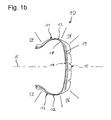
- the tire 10 may, as in Fig. 1a to recognize, lying or, as for example from the DE 203 14 939 U1 is known to be stored upright.
- the axial direction z is vertical and the radial direction r is horizontal.
- the undercarriage 50 is provided with a turning device 51 which allows rotation of the tire 10 about a rotation axis R.
- the rotation axis R extends in the axial direction z.
- a tire 10 usually has two side walls 11, 13 and a side walls 11, 13 interconnecting Tread portion 15 on.
- the transition areas from the tread portion 15 to the sidewalls 11, 13 are generally referred to as a shoulder portion or shoulder 16.
- the free, often thickened end of the side walls 11, 13 provides a firm connection between the tire 10 and the rim of a wheel and is usually referred to as a bead portion or bead 17.
- the load-bearing substructure of the tire 10 is the carcass 18, which generally consists of one or more rubber embedded layers of fabric comprising synthetic fibers or steel cords.
- the carcass 18 is the decisive strength element of the tire 10 and is completed by the belt 19 located in the tread portion 15.
- the measuring heads 21, 22, 23 are first positioned by means of the adjusting units 31, 32, 33, 35, 36, 37 in their respective measuring positions and aligned in their respective measuring directions.
- the measuring heads 21, 22 are aligned for scanning the outer surface 12 of the top wall 11 during a first test run in a direction extending in the axial direction z and positioned in a measuring position in which the respective viewing angle ⁇ of the measuring heads 21, 22 one of In this case, eight measuring sections or sectors, in which the outer surface 12 is structured, completely detected.
- the measuring head 23 is scanned for scanning the inner surface 14 of the tread portion 15 in a measuring direction extending in the radial direction r and positioned in a measuring position in which the viewing angle ⁇ of the measuring head 23 is one of the eight measuring sections in the present case, into which the Inner surface 14 is articulated, completely recorded.
- the measuring sections on the outer surface 12 and the inner surface 14 are then illuminated by means of the respective illumination unit of the measuring heads 21, 22, 23.
- the interfering light bundles are recorded by means of the image sensor of the respective camera of the measuring heads 21, 22, 23 arranged in the beam path of the shearing element in order to generate an interferogram.
- the measuring heads 21, 22, 23 are connected to a control and evaluation device, not shown, which has a multi-channel frame grabber to simultaneously read in the pictures taken by the respective image sensor of the measuring heads 21, 22, 23, ie interferograms.
- the interferograms are processed in the control and evaluation device, for example, to create a shearogram indicative of the deformation on the surface of the tire 10 from different states of the tire 10 resulting from a change in the pressure in the pressure chamber 40.
- the control and evaluation also serves to control the positioning means 30, the rotating device 51 and the pressure prevailing in the pressure chamber 40.
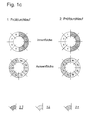
- Fig. 1c all measuring sections on the outer surface 12 of the upper side wall 11 and half of the measuring sections on the inner surface 14 of the tread portion 15 are checked during a first test run.
- the measuring sections 1a to 4a of the measuring head 22 and the measuring sections 5a to 8a are sequentially scanned by the measuring head 21 on the outer surface 12, whereas on the inner surface 14 the measuring sections 1 to 4 are scanned successively by the measuring head 23.
- the tire 10 is intermittently rotated about the rotation axis R.
- the outer surface 12 of the side wall 11 is complete and the inner surface 14 of the tread portion 15 is half checked. The tire 10 is then turned over.
- the outer surface 12 of the then top side wall 13 of the measuring heads 21, 22 and the inner surface 14 of the tread portion 15 is scanned by the measuring head 23.
- the measuring sections 1b to 4b of the measuring head 21 and the measuring sections 5b to 8b of the measuring head 22 are checked successively on the outer surface 12.
- the tire 10 is complete, ie bead to bead, tested.
- the test arrangement shown has two test devices 1a, 1b, which have the same structure as the test device 1 described above and which are arranged one behind the other in a test procedure P.
- a turning device 2 is arranged between the testing devices 1a, 1b, which makes it possible to rotate the tire 10 about a turning axis W extending in the present case in the present case in order to turn the tire 10.
- the above-described first test run is performed on the first test apparatus 1a in the test procedure P
- the second test run is performed on the second test apparatus 1b in the test procedure P.
- the measuring heads 21, 22, 23 of the testing device 1a check the measuring sections 1a to 8a on the outer surface 12 of the side wall 11 and the measuring sections 1 to 4 on the inner surface 14 of the tread section 15.
- the measuring heads 21, 22, 23 of the testing device 1b check After the tire 10 has been turned through the turning device 2, the measuring sections 1b to 8b on the outer surface 12 of the side wall 13 and the measuring sections 5 to 8 on the inner surface 14 of the tread section 15.
- the division of the two test runs on the test devices 1a, 1b enables exceptionally fast screening of tires 10.
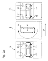
- the in the Fig. 3a and 3b illustrated test apparatus 1c differs from the test apparatus 1 in that the measuring head 21 about a pivot axis S is rotatably mounted.
- the measuring heads 22, 23 of the test apparatus 1c are arranged rigidly in relation to the respective measuring direction. Due to the rotatable mounting of the measuring head 21 can be pivoted by an adjustment angle ⁇ , which in the present case is about 90 °. In this way it is possible, the measuring head 21 between a first measuring position 1, the in Fig. 3a is shown, and a second measuring position II, the in Fig. 3b shown is to pan.
- the measuring head 21 In the first measuring position I, the measuring head 21 is aligned in the axial direction z and consequently makes it possible to check the outer surface 12 of the side walls 11, 13. In the second measuring position II, on the other hand, the measuring head 21 is aligned in the radial direction r and consequently makes it possible to check the inner surface 14 of the tread portion 15.
- the pivotable arrangement of the measuring head 21 is particularly important if the tire 10 is not to be completely tested but only in the region of the tread portion 15. Because in this case, as in Fig. 3b 4, the measuring heads 21, 23 are arranged together inside the tire 10 and are aligned diametrically in order to simultaneously scan the tread portion 15 in a single test run.
- test device 1d differs from the test apparatus 1 primarily in that the measuring device 20 has a fourth measuring head 24.
- the positioning means 30 additionally has an axial adjustment unit 34 and a radial adjustment unit 38 in order to position the measurement head 24 in the desired measurement position.
- the measuring head 24 has the same structure as the measuring heads 21, 22, 23 and is aligned diametrically to the measuring head 23 in the radial direction r. In this way, the inner surface 14 of the tread portion 15 can be scanned by the measuring heads 23, 24 simultaneously in order to achieve a particularly rapid test.
- the test apparatus 1e shown differs from the test apparatus 1d in that the measuring heads 23, 24 are pivotally mounted and thus can be rotated by the adjustment angle ⁇ .
- the adjustment angle ⁇ in the present case is about +/- 25 ° relative to the in Fig. 1b shown tire center plane E or parallel to the tire center plane E level.
- the measuring heads 23, 24 are each pivoted upwards and thus allow a split-crown shot on the tread portion 15 including the shoulder 16.
- Fig. 5a the measuring heads 23, 24 are each pivoted upwards and thus allow a split-crown shot on the tread portion 15 including the shoulder 16.
- the measuring head 23 upwards, the measuring head 24, however, pivoted downwards, so that the measuring head 23 is a split-crown shot on the tread portion 15 including the upper shoulder 16 and the measuring head 24 is a split-crown shot on the tread portion 15 including lower shoulder 16 performs.
- the pivotable arrangement of the measuring heads 23, 24 is particularly useful when the tire to be tested 10 has a comparatively large width and / or a small jaw width, so that the tread portion 15 in an alignment of the measuring heads 23, 24 in the radial direction r would not be completely detected by the viewing angle ⁇ of the measuring heads 23, 24.
- the above-described embodiments of a device for testing the tire 10 are characterized in that a rapid and complete testing of the tire 10 is possible.
- the test devices 1, 1a, 1b, 1c have only three measuring heads 21, 22, 23 and thus have an optimum configuration in order to completely test the tire 10 when carrying out the method according to the invention.
- the testing devices 1d, 1e which have four measuring heads 21, 22, 23, 24, likewise make it possible to carry out the method according to the invention, but because of the fourth measuring head 24 not only provide redundancy which contributes to a high degree of reliability, but also make it possible to carry out a wide variety of process guides realize.
- the rigid arrangement of most of the measuring heads 21, 22, 23, 24 of the test devices 1, 1a, 1b, 1c, 1d, 1e contributes to a simple and cost-effective design, which the wear and maintenance is low.
Abstract
Description
Die vorliegende Erfindung betrifft eine Vorrichtung und ein Verfahren zum Prüfen eines Reifens, insbesondere mittels eines interferometrischen Messverfahrens. Bei dem zu prüfenden Objekt handelt es sich um einen Reifen, jedoch können auch andere Bauteile mit der erfindungsgemäßen Vorrichtung geprüft werden. Das Messverfahren, mit dem der Reifen geprüft wird, ist insbesondere ein interferometrisches Messverfahren. Allerdings ist es auch möglich, andere zerstörungsfreie Messverfahren, wie zum Beispiel Ultraschallprüfung oder Durchstrahlungsprüfung mittels Röntgenstrahlen, durchzuführen. Die Vorrichtung weist eine Messeinrichtung auf, durch die der Reifen zum Erzeugen eines Messergebnisses abgetastet werden kann. Die Vorrichtung ist ferner mit einem Positionierungsmittel versehen, durch das die Messeinrichtung in einer Messposition positioniert und in einer Messrichtung ausgerichtet werden kann.The present invention relates to an apparatus and a method for testing a tire, in particular by means of an interferometric measuring method. The object to be tested is a tire, but other components can also be tested with the device according to the invention. The measuring method with which the tire is tested is in particular an interferometric measuring method. However, it is also possible to perform other non-destructive measuring methods, such as ultrasonic testing or X-ray radiographic examination. The device has a measuring device, by means of which the tire can be scanned to produce a measurement result. The device is further provided with a positioning means by which the measuring device can be positioned in a measuring position and aligned in a measuring direction.
Reifen oder andere im Einsatz belastete Bauteile werden zur Qualitätskontrolle und zur Reduzierung von Sicherheitsrisiken einer Werkstoffprüfung unterzogen, die es ermöglicht, fehlerhafte Stellen, sogenannte Fehlstellen, zu erkennen. Vor allem dann, wenn es sich um benutzte Reifen handelt, die runderneuert werden sollen, wird in der Regel eine zerstörungsfreie Werkstoffprüfung angewendet, die eine vergleichsweise schnelle Reihenuntersuchung gewährleistet.Tires or other components subject to load are subjected to a material test for quality control and to reduce safety risks, which makes it possible to detect faulty areas, so-called defects. In particular, when it comes to used tires that are to be retreaded, a non-destructive material testing is usually applied, which ensures a comparatively quick screening.
Häufig anzutreffen in der industriellen Praxis sind optische Messverfahren, wie zum Beispiel die Holographie oder die auch als Speckle-Pattern-Shearing-Interferometrie bezeichnete Shearographie. Die Shearographie ist ein relatives interferometrisches Messverfahren, das ein Ergebnisbild liefert, welches den Unterschied zwischen zwei zeitlich versetzten Zuständen des Prüfobjekts darstellt. Um das auf Grund der zunehmenden Verbreitung von elektronischen Bildsensoren, wie zum Beispiel CCD- oder CMOS-Sensoren, heutzutage in der Regel digitale Ergebnisbild zu erzeugen, ist es demzufolge erforderlich, den Zustand des Prüfobjekts zwischen zwei Messungen durch Einwirkung einer mechanischen, thermischen oder pneumatischen Kraft zu verändern. Bekannte Vorrichtungen weisen aus diesem Grund eine Druckkammer auf, die entweder evakuiert oder mit Druck beaufschlagt wird, so dass sich das in der Druckkammer befindende Prüfobjekt infolge der Druckänderung verformt und damit von einem ersten Referenzzustand in einen zweiten Messzustand übergeht.Frequently encountered in industrial practice are optical measuring techniques, such as holography or shearography, also referred to as speckle-pattern shearing interferometry. Shearography is a relative interferometric measurement technique that provides a result image that represents the difference between two staggered states of the test object. In order to generate a digital result image today due to the increasing popularity of electronic image sensors, such as CCD or CMOS sensors, it is therefore necessary to change the state of the test object between two measurements by the action of a mechanical, thermal or pneumatic Force to change. For this reason, known devices have a pressure chamber which is either evacuated or pressurized so that the test object located in the pressure chamber is deformed as a result of the pressure change and thus changes from a first reference state into a second measuring state.
Im Unterschied zu der Holographie ermittelt die Shearographie nicht die Verformung an der Oberfläche eines Prüfobjekts, sondern misst den Gradienten der Verformung. Dies ist darauf zurückzuführen, dass für die Shearographie ein sogenanntes Shearingelement Anwendung findet, bei dem es sich um eine Shearoptik, wie zum Beispiel ein optischer Keil, ein optisches Biprisma oder ein Michelson-Interferometer, handelt, die eine Bildverdopplung erzeugt. Auf Grund des Shearingelements entstehen zwei geringfügig räumlich versetzte Bilder von dem Prüfobjekt, die überlagert werden, um auf Grund der sich auf diese Weise ergebenden Interferenz ein Interferogramm zu erzeugen. Das den Gradienten der Verformung kennzeichnende Shearogramm wird durch Subtraktion der Intensitäten der im Referenzzustand und im Messzustand gewonnenen Interferogramme erzeugt. Das Shearogramm gibt zu erkennen, ob sich die Lage eines Punktes zu einem benachbarten Punkt auf Grund der Verformung des Prüfobjekts geändert hat. Falls ja, dann führt dieser Wegunterschied zu einer lokalen Veränderung der Intensitätsverteilung, die Auskunft über eine Fehlstelle gibt. Interferometrische Messverfahren, die auf dieser Speckle-Interferomertrie beruhen, werden in der
Die zum Prüfen eines Prüfobjekts mittels eines interferometrischen Messverfahrens eingesetzten Vorrichtungen sind in der Regel mit wenigstens einem Messkopf versehen, der eine Beleuchtungseinheit und eine Bildaufnahmeeinheit aufweist. Die Beleuchtungseinheit wird häufig durch einen kohärentes Licht emittierenden Laser oder Laserdioden gebildet. Die Bildaufnahmeeinheit ist üblicherweise eine Kamera, die mit einem Bildsensor, das heißt einem lichtempfindlichen Halbleitersensor, zum Beispiel einem CCD- oder CMOS-Sensor, versehen ist. Um ein aussagekräftiges Messergebnis zu erhalten, ist es erforderlich, das Gesichtsfeld der Kamera und den zu prüfenden Abschnitt des Prüfobjekts aufeinander abzustimmen. Gewöhnlich erfolgt eine solche Abstimmung dadurch, dass der Messkopf in einer Messposition positioniert und in einer Messrichtung ausgerichtet wird, die sicherstellen, dass einerseits der gewählte Messabschnitt des Prüfobjekts vollständig von dem Gesichtswinkel der Kamera erfasst wird und damit im Gesichtsfeld der Kamera liegt und andererseits aufeinander folgende Messabschnitte sich ausreichend überlappen, um eine lückenlose Prüfung zu ermöglichen. Die Messposition und die Messrichtung des Messkopfs hängen von den Abmessungen des Prüfobjekts ab. Demzufolge ist aus der
Ein Reifenprüfgerät, bei dem ein zu prüfender Reifen ohne Felge und Radscheibe in einer liegenden Position in einer Druckkammer angeordnet wird, offenbart die
Die Messköpfe sind mit einem Positionierungsmittel verbunden, das es ermöglicht, die Messköpfe von einer sich außerhalb des Reifens befindenden und somit einen Wechsel der zu prüfenden Reifen gewährleistenden Parkposition in eine sich innerhalb des Reifens befindende Messposition zu bewegen. Zu diesem Zweck weist das Positionierungsmittel einen in der axialen Richtung des Reifens verstellbaren Arm auf, an dem die Messköpfe angeordnet sind. Um die Messköpfe in der erforderlichen Messposition positionieren und in der gewünschten Messrichtung ausrichten zu können, sind die Messköpfe in radialer Richtung des Reifens verstellbar und um eine Schwenkachse drehbar an dem Arm angeordnet.The measuring heads are connected to a positioning means which makes it possible to move the measuring heads from a parking position which is located outside of the tire and thus ensures a change of the tires to be tested into a measuring position located within the tire. For this purpose, the positioning means on an adjustable in the axial direction of the tire arm on which the measuring heads are arranged. In order to position the measuring heads in the required measuring position and to be able to align them in the desired measuring direction, the measuring heads are adjustable in the radial direction of the tire and are arranged rotatably on the arm about a pivot axis.
Das bekannte Reifenprüfgerät ist mit dem Nachteil verbunden, dass aufgrund der Anordnung der Messköpfe in der sich innerhalb des Reifens befindenden Messposition nur Reifen geprüft werden können, die einen vergleichsweise großen Innendurchmesser haben. Darüber hinaus hat sich die um eine Schwenkachse drehbare Anordnung der Messköpfe, die zwingend erforderlich ist, um die Innenfläche des Reifens vollständig prüfen zu können, als nachteilig erwiesen. Denn die schwenkbare Anordnung der Messköpfe erfordert einen hohen mechanischen und steuerungstechnischen Aufwand, der mit einer kostenintensiven Fertigung einhergeht.The known tire testing device is associated with the disadvantage that, due to the arrangement of the measuring heads in the measuring position located within the tire, only tires which have a comparatively large inner diameter can be tested. In addition, the rotatable about a pivot axis arrangement of the measuring heads, which is imperative to be able to fully test the inner surface of the tire, has proved to be disadvantageous. Because the pivotable arrangement of the measuring heads requires a high mechanical and control engineering effort, which is associated with a costly production.
Der Erfindung liegt die Aufgabe zugrunde, eine Vorrichtung und ein Verfahren sowie eine Prüfanordnung zum Prüfen eines Reifens zu schaffen, die eine schnelle und vollständige Prüfung des Reifens ermöglichen.The invention has for its object to provide an apparatus and a method and a test arrangement for testing a tire, which allow a quick and complete testing of the tire.
Diese Aufgabe wird durch eine Vorrichtung gemäß Anspruch 1, eine Prüfanordnung gemäß Anspruch 24 und ein Verfahren gemäß Anspruch 25 gelöst. Bevorzugte Ausgestaltungen der Erfindung werden in den Ansprüchen 2 bis 23 und 26 bis 30 definiert.This object is achieved by an apparatus according to
Die erfindungsgemäße Vorrichtung zum Prüfen eines Reifens weist eine Messeinrichtung auf, durch die der Reifen zum Erzeugen eines Messergebnisses abtastbar ist. Die Messeinrichtung weist wenigstens drei Messköpfe auf, die zum Beispiel eine Ausgestaltung haben können, wie sie in der
Das Positionierungsmittel ist so ausgestaltet, dass wenigstens zwei der Messköpfe der Messeinrichtung in Messrichtungen ausgerichtet werden können, die es ermöglichen, die Außenfläche der Seitenwände abzutasten. Das Positionierungsmittel ist außerdem so ausgestaltet, dass wenigstens einer der Messköpfe der Messeinrichtung in einer Messrichtung ausgerichtet werden kann, die es ermöglicht, die Innenfläche des Reifens, und zwar zumindest im Bereich des Laufflächenabschnitts, abzutasten.The positioning means is designed so that at least two of the measuring heads of the measuring device can be aligned in measuring directions, which make it possible to scan the outer surface of the side walls. The positioning means is also designed so that at least one of the measuring heads of the measuring device can be aligned in a measuring direction which makes it possible to scan the inner surface of the tire, at least in the region of the tread portion.
Das erfindungsgemäße Verfahren ermöglicht eine schnelle und vollständige Prüfung des Reifens, wenn die Prüfvorrichtung wenigstens drei Messköpfe aufweist. Der erste Messkopf und der zweite Messkopf werden so positioniert und ausgerichtet, dass die Außenfläche der Seitenwände abgetastet werden kann. Der dritte Messkopf wird hingegen so positioniert und ausgerichtet, dass sich die Innenfläche von zumindest dem Laufflächenabschnitt abtasten lässt. In einem ersten Prüfdurchlauf wird der Reifen relativ zu den Messköpfen um die Rotationsachse intermittierend gedreht und von den Messköpfen abschnittsweise abgetastet. Der erste Messkopf tastet dabei eine Hälfte der Messabschnitte auf der Außenfläche der ersten Seitenwand ab, wohingegen der zweite Messkopf die andere Hälfte der Messabschnitte auf der Außenfläche der ersten Seitenwand abtastet. Der dritte Messkopf tastet eine Hälfte der Messabschnitte auf der Innenfläche ab. Nach dem ersten Prüfdurchlauf wird der Reifen gewendet und anschließend in einem zweiten Prüfdurchlauf erneut relativ zu den Messköpfen um die Rotationsachse intermittierend gedreht und von den Messköpfen abschnittsweise abgetastet. Der erste Messkopf tastet dann eine Hälfte der Messabschnitte auf der Außenfläche der zweiten Seitenwand ab, wohingegen der zweite Messkopf die andere Hälfte der Messabschnitte auf der Außenfläche der zweiten Seitenwand abtastet. Der dritte Messkopf tastet die verbleibende Hälfte der Messabschnitte auf der Innenfläche ab.The method according to the invention makes it possible to test the tire quickly and completely when the testing device has at least three measuring heads. The first probe and the second probe are positioned and aligned so that the outer surface of the sidewalls can be scanned. By contrast, the third measuring head is positioned and aligned so that the inner surface of at least the tread portion can be scanned. In a first test run, the tire is rotated intermittently relative to the measuring heads about the axis of rotation and scanned in sections by the measuring heads. The first measuring head scans one half of the measuring sections on the outer surface of the first side wall, whereas the second measuring head scans the other half of the measuring sections on the outer surface of the first side wall. The third measuring head scans half of the measuring sections on the inner surface. After the first test run, the tire is turned and then intermittently rotated again in a second test run relative to the measuring heads about the axis of rotation and scanned in sections by the measuring heads. The first measuring head then scans one half of the measuring sections on the outer surface of the second side wall, whereas the second measuring head scans the other half of the measuring sections on the outer surface of the second side wall. The third measuring head scans the remaining half of the measuring sections on the inner surface.
Demzufolge sind nach dem zweiten Prüfdurchlauf die Außenfläche von sowohl der ersten Seitenwand als auch der zweiten Seitenwand sowie die Innenfläche von zumindest dem Laufflächenabschnitt komplett abgetastet und der Reifen damit vollständig geprüft. Die Erfindung macht sich die Erkenntnis zu eigen, eine vollständige Prüfung des Reifens, das heißt eine sogenannte bead-to-bead-Prüfung, dadurch zu erreichen, dass die Seitenwände von außen und der Laufflächenabschnitt von innen geprüft wird. Die Seitenwände werden dabei mit Hilfe von zwei Messköpfen abgetastet, wohingegen für das Abtasten des Laufflächenabschnitts ein einziger Messkopf ausreichend ist.Accordingly, after the second test run, the outer surface of both the first sidewall and the second sidewall and the inner surface of at least the tread portion are completely scanned and the tire is thus fully tested. The invention embraces the finding of a complete test of the tire, that is to say a so-called bead-to-bead test, to be achieved by checking the side walls from the outside and the tread portion from the inside. The side walls are scanned with the aid of two measuring heads, whereas a single measuring head is sufficient for the scanning of the tread portion.
Die Erfindung ist von besonderer Bedeutung, wenn der Reifen in einer liegenden Position geprüft wird und demzufolge ein Wenden des Reifens unerlässlich ist, um die während des ersten Prüfdurchlaufs untenliegende Seitenwand in dem zweiten Prüfdurchlauf von außen prüfen zu können. Sind, wie in solch einem Fall, zwei Prüfdurchläufe notwendig, dann kommt in besonderem Maße die Aufteilung der Prüfung des Laufflächenabschnitts auf die zwei Prüfdurchläufe zum Tragen. Denn durch diese Aufteilung kann in der Zeitspanne, während der die beiden Messköpfe die Seitenwände von außen prüfen, der Laufflächenabschnitt mit nur einem einzigen Messkopf vollständig geprüft werden. Im Unterschied zum Stand der Technik, wie er beispielsweise aus der
Wenngleich sich demzufolge eine Anzahl von drei Messköpfen für die Prüfung der meisten Reifentypen als optimal erweist, kann die erfindungsgemä-βe Vorrichtung bei Bedarf auch mit mehr als drei Messköpfen bestückt werden. Werden zum Beispiel vergleichsweise große Reifen, wie etwa so genannte Off-The-Road (OTR)-Reifen, geprüft, dann kann es sich als zweckmäßig erweisen, die Seitenwände nicht mit zwei, sondern mit vier oder mehr Messköpfen von außen zu prüfen, um eine kurze Prüfdauer zu erreichen. Der dem erfindungsgemäßen Verfahren immanente Vorteil, die zwei, sich durch ein Wenden des Reifens ergebenden Prüfdurchläufe auszunutzen, um die Prüfung des Laufflächenabschnitts auf die beiden Prüfdurchläufe zu verteilen, ergibt sich immer dann, wenn die Anordnung der Messköpfe, welche die Seitenwände von außen prüfen, und die Anordnung der Messköpfe, welche den Laufflächenabschnitt von innen prüfen, so gewählt werden, dass während eines Prüfdurchlaufs die Außenfläche der Seitenwände vollständig und die Innenfläche des Laufflächenabschnitts zur Hälfte geprüft werden.Thus, although a number of three probes proves to be optimal for testing most types of tires, the device of the present invention can be equipped with more than three probes if desired. For example, if comparatively large tires, such as so-called off-the-road (OTR) tires, are tested, then it may be useful to test the side walls not with two, but with four or more measuring heads from the outside to achieve a short test duration. The inherent advantage of the method according to the invention of exploiting the two test runs resulting from turning of the tire in order to distribute the test of the tread portion over the two test runs is always obtained when the arrangement of the measuring heads which check the side walls from the outside, and the arrangement of the measuring heads, which check the tread portion from the inside, be selected so that during a test run, the outer surface of the side walls are fully tested and the inner surface of the tread portion in half.
Ein weiterer Grund für das Vorsehen von mehr als drei Messköpfen kann darin bestehen, Redundanz zu schaffen, um eine ausfallsichere Ausgestaltung zu erreichen. Darüber hinaus ist es mitunter ausreichend, wenn der Reifen nicht vollständig geprüft wird, sondern lediglich im Bereich des Laufflächenabschnitts. Um in diesem Fall eine kurze Prüfdauer sicherzustellen, umfasst die Messeinrichtung in einer bevorzugten Ausgestaltung der erfindungsgemäßen Vorrichtung einen vierten Messkopf, der zum Abtasten der Innenfläche von zumindest dem Laufflächenabschnitt in einer vierten Messrichtung ausgerichtet ist. Die vierte Messrichtung und die dritte Messrichtung, in welcher der dritte Messkopf ausgerichtet ist, verlaufen bevorzugt in einer radialen Richtung des Reifens und sind zu dem vorgenannten Zweck vorzugsweise entgegengesetzt orientiert. Je nach Anwendungsfall ist es allerdings auch möglich, dass sich die dritte und vierte Messrichtung geneigt zu der Reifenmittenebene erstreckt, die bei einem symmetrischen Aufbau des Reifens dessen Symmetrieebene entspricht.Another reason for providing more than three probes may be to provide redundancy to achieve a fail-safe design. In addition, it is sometimes sufficient if the tire is not fully tested, but only in the area of the tread portion. In order to ensure a short test duration in this case, the measuring device in a preferred embodiment of the device according to the invention comprises a fourth measuring head, which is aligned for scanning the inner surface of at least the tread portion in a fourth measuring direction. The fourth measuring direction and the third measuring direction, in which the third measuring head is aligned, preferably run in a radial direction of the tire and are preferably oriented opposite to the aforementioned purpose. Depending on the application, however, it is also possible that the third and fourth measuring direction extends inclined to the tire center plane, which corresponds to the symmetrical plane of a symmetrical structure of the tire.
Die erste Messrichtung und die zweite Messrichtung verlaufen bevorzugt in einer axialen Richtung des Reifens. Je nach Anwendungsfall ist es allerdings auch möglich, dass die erste und zweite Messrichtung geneigt zu einer sich in der axialen Richtung erstreckenden Axialebene verlaufen.The first measuring direction and the second measuring direction preferably extend in an axial direction of the tire. However, depending on the application, it is also possible that the first and second measuring directions are inclined to an axial plane extending in the axial direction.
Eine dem erfindungsgemäßen Verfahren in besonderem Maße Rechnung tragende Prüfung ergibt sich dann, wie oben dargetan, wenn der Reifen in einer liegende Position geprüft wird. In diesem Fall verläuft die axiale Richtung vertikal, wohingegen die radiale Richtung horizontal verläuft. Je nach Anwendungsfall kann es allerdings zweckmäßig sein, den Reifen in einer aufrechten Position zu prüfen, so dass die axiale Richtung horizontal verläuft, wie es zum Beispiel aus der
In einer bevorzugten Ausgestaltung der erfindungsgemäßen Vorrichtung ist zumindest einer der Messköpfe in Bezug auf die Messrichtung starr angeordnet. Vorzugsweise sind alle Messköpfe in Bezug auf ihre jeweilige Messrichtung starr angeordnet. Die starre Anordnung der Messköpfe, das heißt die fehlende Möglichkeit, die Messköpfe in der Messposition um eine orthogonal zu der Messrichtung verlaufende Schwenkachse zu drehen, bietet den Vorteil einer einfachen und damit kostengünstigen Ausgestaltung. Im Unterschied zum Stand der Technik, wie er zum Beispiel aus der
In einer alternativen Ausgestaltung der erfindungsgemäßen Vorrichtung ist zumindest einer der Messköpfe, vorzugsweise alle Messköpfe, um eine orthogonal zu der Messrichtung verlaufende Schwenkachse drehbar. In Hinsicht auf eine einfache und universelle Ausgestaltung hat es sich als vorteilhaft und ausreichend erwiesen, wenn nur einer der Messköpfe um die Schwenkachse drehbar ist.In an alternative embodiment of the device according to the invention, at least one of the measuring heads, preferably all the measuring heads, is rotatable about a pivot axis extending orthogonally to the measuring direction. With regard to a simple and universal design, it has proven to be advantageous and sufficient if only one of the measuring heads is rotatable about the pivot axis.
In einer bevorzugten Ausgestaltung der erfindungsgemäßen Vorrichtung kann der Messkopf zwischen einer ersten Messposition und einer zweiten Messposition geschwenkt werden. Um eine präzise und reproduzierbare Schwenkbewegung zu erreichen, ist der Messkopf vorteilhafterweise entgegen der Wirkung einer beispielsweise von einem Federelement hervorgerufenen Rückstellkraft von der ersten Messposition in die zweite Messposition schwenkbar. Die Bewegung von der ersten Messposition in die zweite Messposition kann zum Beispiel durch ein pneumatisch betätigtes Stellglied erzeugt werden.In a preferred embodiment of the device according to the invention, the measuring head can be pivoted between a first measuring position and a second measuring position. In order to achieve a precise and reproducible pivoting movement, the measuring head is advantageously pivotable from the first measuring position to the second measuring position counter to the effect of a restoring force caused, for example, by a spring element. The movement from the first measuring position to the second measuring position can be generated, for example, by a pneumatically actuated actuator.
Bevorzugt ist der Messkopf in der ersten Messposition in einer sich im Wesentlichen in der axialen Richtung des Reifens erstreckenden Messrichtung und in der zweiten Messposition in einer sich im Wesentlichen in der radialen Richtung des Reifens erstreckenden Messrichtung ausgerichtet. In der ersten Messposition kann der Messkopf eingesetzt werden, um die Seitenwände des Reifens von außen zu prüfen. In der zweiten Messposition kann der Messkopf eingesetzt werden, um den Laufflächenabschnitt des Reifens von innen zu prüfen. Handelt es sich bei dem schwenkbar angeordneten Messkopf um den ersten Messkopf oder den zweiten Messkopf, dann kann dieser in der zweiten Messposition zusammen mit dem dritten Messkopf den Laufflächenabschnitt in einer vergleichsweise kurzen Prüfdauer abtasten, wenn keine vollständige Prüfung des Reifens erforderlich ist. Die schwenkbare Anordnung von nur einem der Messköpfe gewährleistet somit eine universelle Verwendbarkeit der erfindungsgemäßen Vorrichtung.In the first measuring position, the measuring head is preferably aligned in a measuring direction extending essentially in the axial direction of the tire, and in the second measuring position in a measuring direction extending substantially in the radial direction of the tire. In the first measuring position, the measuring head can be inserted around the side walls the outside of the tire. In the second measuring position, the measuring head can be used to check the tread portion of the tire from the inside. If the pivotally arranged measuring head is the first measuring head or the second measuring head, then in the second measuring position it can scan the tread portion together with the third measuring head in a comparatively short test duration, if complete testing of the tire is not required. The pivotable arrangement of only one of the measuring heads thus ensures a universal usability of the device according to the invention.
In einer weiteren bevorzugten Ausgestaltung der erfindungsgemäßen Vorrichtung ist der Messkopf derart schwenkbar, dass er in der ersten Messposition in einer sich in der radialen Richtung des Reifens erstreckenden Messrichtung und in der zweiten Messposition in einer gegenüber dieser radialen Messrichtung um einen Verstellwinkel geneigten Messrichtung ausgerichtet ist. Eine solche Ausgestaltung bietet sich vor allem dann an, wenn die zu prüfenden Reifen über eine vergleichsweise große Breite verfügen und infolgedessen der Laufflächenabschnitt nicht vollständig von dem Gesichtswinkel des Messkopfs erfasst wird. Auf Grund der Drehung des Messkopfs um den Verstellwinkel ist es möglich, einen so genannten Split-Crown-Shot durchzuführen, das heißt den Messkopf so auszurichten, dass ein Teil des Laufflächenabschnitts einschließlich des sich im Übergang zu der Seitenwand befindenden Schulterabschnitts in dem Gesichtswinkel des Messkopfs liegt. Zu diesem Zweck hat es sich als vorteilhaft erwiesen, wenn der Verstellwinkel, bezogen auf die Reifenmittenebene, zwischen 0° und ± 30°, vorzugsweise zwischen 0° und ± 15°, beträgt. Wird die Innenfläche des Reifens mittels eines Split-Crown-Shot geprüft, dann lassen sich die Vorteile des erfindungsgemäßen Verfahrens erreichen, wenn die Innenfläche des Reifens von zwei Messköpfen simultan abgetastet wird.In a further preferred embodiment of the device according to the invention, the measuring head is pivotable such that it is aligned in the first measuring position in a measuring direction extending in the radial direction of the tire and in the second measuring position in a measuring direction inclined relative to this radial measuring direction by an adjusting angle. Such a configuration is particularly suitable when the tires to be tested have a comparatively large width and, as a result, the tread portion is not completely covered by the viewing angle of the measuring head. Due to the rotation of the measuring head about the displacement angle, it is possible to perform a so-called split-crown shot, that is to align the measuring head so that a part of the tread portion including the shoulder portion located in the transition to the side wall in the viewing angle of the measuring head lies. For this purpose, it has proven to be advantageous if the adjustment angle, relative to the tire center plane, between 0 ° and ± 30 °, preferably between 0 ° and ± 15 °. If the inner surface of the tire is checked by means of a split-crown shot, the advantages of the method according to the invention can be achieved if the inner surface of the tire is scanned simultaneously by two measuring heads.
In einer weiteren bevorzugten Ausgestaltung weist die erfindungsgemäße Vorrichtung eine Druckkammer auf, in welcher der zu prüfende Reifen einem vorgegebenen Druck ausgesetzt werden kann. Die Druckkammer ermöglicht, ein interferometrisches, insbesondere shearographisches, Messverfahren praxisgerecht durchzuführen.In a further preferred embodiment, the device according to the invention has a pressure chamber in which the tire to be tested can be exposed to a predetermined pressure. The pressure chamber makes it possible to carry out an interferometric, in particular shearographic, measuring method in a practical manner.
Bevorzugt weist die erfindungsgemäße Vorrichtung außerdem ein Untergestell auf, auf dem der Reifen während der Prüfung lagerbar ist. Das Untergestell kann zudem dazu dienen, auftretende Schwingungen, wie zum Beispiel Luft- oder Körperschall, die das Messergebnis verfälschten, zu minimieren. Zweckmäßigerweise sind das Positionierungsmittel und/oder die Druckkammer an dem Untergestell abgestützt.Preferably, the device according to the invention also has a base on which the tire can be stored during the test. The undercarriage can also serve to minimize occurring vibrations, such as airborne or structure-borne noise, which falsified the measurement result. Conveniently, the positioning means and / or the pressure chamber are supported on the base frame.
In einer weiteren bevorzugten Ausgestaltung der erfindungsgemäßen Vorrichtung ist wenigstens einer der Messköpfe durch das Positionierungsmittel in der axialen Richtung und/oder in der radialen Richtung bewegbar. In diesem Zusammenhang hat es sich als vorteilhaft erwiesen, wenn das Positionierungsmittel wenigstens eine axiale Verstelleinheit, durch die der Messkopf in der axialen Richtung bewegbar ist, und wenigstens eine radiale Verstelleinheit, durch die der Messkopf in der radialen Richtung bewegbar ist, aufweist. Zweckmäßigerweise sind jedem der Messköpfe eine axiale Verstelleinheit und eine radiale Verstelleinheit zugeordnet, so dass die Messköpfe unabhängig voneinander in ihrer jeweiligen Messposition positioniert und in ihrer jeweiligen Messrichtung ausgerichtet werden können. Die Verstelleinheiten sind beispielsweise als Linearführung oder Linearmotor ausgestaltet und können miteinander gekoppelt sein. Eine einfache und kostengünstige Ausgestaltung ergibt sich dann, wenn wenigstens zwei radiale Verstelleinheiten und/oder wenigstens zwei axiale Verstelleinheiten jeweils miteinander gekoppelt sind, und zwar derart, dass sie durch einen gemeinsamen Antrieb angetrieben werden.In a further preferred embodiment of the device according to the invention, at least one of the measuring heads is movable by the positioning means in the axial direction and / or in the radial direction. In this context, it has proved to be advantageous if the positioning means has at least one axial adjustment unit, by means of which the measuring head can be moved in the axial direction, and at least one radial adjustment unit, by means of which the measuring head can be moved in the radial direction. Expediently, each of the measuring heads is assigned an axial adjusting unit and a radial adjusting unit, so that the measuring heads can be positioned independently of one another in their respective measuring position and aligned in their respective measuring direction. The adjustment units are configured for example as a linear guide or linear motor and can be coupled together. A simple and cost-effective embodiment results when at least two radial adjustment units and / or at least two axial adjustment units are each coupled to each other, in such a way that they are driven by a common drive.
Weiterhin ist es von Vorteil, wenn die Messeinrichtung relativ zu dem Reifen um eine sich in der axialen Richtung des Reifens erstreckende Rotationsachse oder Rollachse drehbar ist, um auf diese Weise den Reifen in Umfangsrichtung vollständig abzutasten. In diesem Zusammenhang ist es ferner vorteilhaft, das Untergestell mit einer Drehvorrichtung zu versehen, durch die der Reifen um die Rotationsachse gedreht werden kann. Alternativ oder zusätzlich kann die Relativbewegung von Reifen und Messeinrichtung durch eine drehbare Ausgestaltung des Positionierungsmittels erreicht werden. Letztere Ausgestaltung ist jedoch mit einem hohen technischen Aufwand und enormen Platzbedarf verbunden.Furthermore, it is advantageous if the measuring device is rotatable relative to the tire about an axis of rotation or rolling axis extending in the axial direction of the tire so as to fully scan the tire in the circumferential direction in this way. In this context, it is also advantageous to provide the underframe with a rotating device, by which the tire can be rotated about the axis of rotation. Alternatively or additionally, the relative movement of tire and measuring device can be achieved by a rotatable embodiment of the positioning means. The latter embodiment, however, is associated with a high technical complexity and enormous space requirements.
Um ein interferometrisches, insbesondere shearographisches, Messverfahren durchzuführen, umfassen die Messköpfe vorteilhafterweise jeweils eine Beleuchtungseinheit, durch die der zu prüfende Reifen beleuchtet wird, ein Shearingelement, durch das die von dem Reifen rückgestreuten Lichtbündel zur Interferenz gebracht werden, und einen elektronischen Bildsensor, der im Strahlengang des Shearingelements angeordnet ist und die interferierenden Lichtbündel aufnimmt. Die zum Beispiel durch Laserdioden gebildete Beleuchtungseinheit kann entweder integraler Bestandteil der Messköpfe oder von diesen separat ausgebildet sein.In order to carry out an interferometric, in particular shearographic, measuring method, the measuring heads advantageously each comprise a lighting unit, by means of which the tire to be tested is illuminated, a shearing element, by which the light beams backscattered by the tire are brought into interference, and an electronic image sensor, which in FIG Beam path of the Shearingelements is arranged and receives the interfering light beam. The illumination unit formed for example by laser diodes can either be an integral part of the measuring heads or be formed separately from them.
In Hinsicht auf eine praxisgerechte Ausgestaltung ist es außerdem von Vorteil, wenn die erfindungsgemäße Vorrichtung eine Steuer- und Auswerteeinrichtung aufweist, mittels der die Messeinrichtung und/oder das Positionierungsmittel und/oder die Drehvorrichtung und/oder der in der Druckkammer herrschende Druck gesteuert und das erzielte Messergebnis ausgewertet werden können. In diesem Zusammenhang hat es sich zudem als vorteilhaft erwiesen, wenn die Steuer- und Auswerteinrichtung eine Bildfangschaltung, das heißt einen so genannten Frame- oder Videograbber, aufweist, durch welche die von dem Bildsensor der Messköpfe aufgenommenen Bilder eingelesen werden. Die Bildfangschaltung ist zweckmäßigerweise mehrkanalig ausgestaltet, um die Bilder der Messköpfe simultan einlesen zu können. Eine besonders kostengünstige Ausgestaltung ergibt sich dann, wenn die Messeinrichtung über drei Messköpfe verfügt und für das simultane Einlesen der Bilder demzufolge eine dreikanalige Bildfangschaltung erforderlich ist. Denn dreikanalige Framegrabber werden für die Verarbeitung von Videosignalen herkömmlicher Farbkameras eingesetzt und sind daher günstig am Markt zu erwerben. Je nach Anwendungsfall kann es allerdings sinnvoll sein, die von dem Bildsensor erzeugten Bildsignale nicht simultan, sondern sequenziell einzuziehen, um beispielsweise bei einer großen Anzahl an Messköpfen eine einfache und kostengünstige Bildfangschaltung verwenden zu können.With regard to a practical embodiment, it is also advantageous if the device according to the invention has a control and evaluation, controlled by means of which the measuring device and / or the positioning means and / or the rotating device and / or prevailing in the pressure chamber pressure and achieved Measurement result can be evaluated. In this context, it has also proven to be advantageous if the control and evaluation device has a frame grabber, that is to say a so-called frame or video grabber, through which the images recorded by the image sensor of the measuring heads are read. The image capture circuit is expediently multi-channel designed to be able to read in the images of the measuring heads simultaneously. A particularly cost-effective embodiment results when the measuring device has three measuring heads and therefore a three-channel frame grabber is required for the simultaneous reading of the images. Because three-channel frame grabbers are used for processing video signals from conventional color cameras and are therefore inexpensive to buy on the market. Depending on the application, however, it may be useful not to simultaneously feed the image signals generated by the image sensor, but sequentially, in order to use a simple and inexpensive image capture circuit, for example, in a large number of probes.
In einer bevorzugten Ausgestaltung des erfindungsgemäßen Verfahrens werden die Seitenwände und der Laufflächenabschnitt jeweils in eine gerade Anzahl an Messabschnitten gegliedert. Als für die meisten Reifentypen geeignet hat sich eine Gliederung in acht Messabschnitte erwiesen.In a preferred embodiment of the method according to the invention, the side walls and the tread portion are each divided into an even number of measuring sections. As suitable for most tire types, a breakdown into eight measuring sections has been found.
In einer besonders vorteilhaften Ausgestaltung des erfindungsgemäßen Verfahrens werden der erste Prüfdurchlauf auf einer ersten Prüfvorrichtung und der zweite Prüfdurchlauf auf einer zweiten Prüfvorrichtung durchgeführt. Eine solche Verfahrensführung ermöglicht eine außerordentlich schnelle Reihenuntersuchung.In a particularly advantageous embodiment of the method according to the invention, the first test run is performed on a first test apparatus and the second test run on a second test apparatus. Such a procedure allows an extremely fast screening.
In einer weiteren bevorzugten Ausgestaltung des erfindungsgemäßen Verfahrens werden die Messabschnitte von den Messköpfen simultan abgetastet, wobei der Reifen zweckmäßigerweise in einer Druckkammer abgeordnet und einem vorgegebenen Druck ausgesetzt wird, so dass die Messköpfe eine sich auf Grund einer Änderung des Drucks in der Druckkammer ergebende Verformung des Reifens interferometrisch erfassen können.In a further preferred embodiment of the method according to the invention, the measuring sections are scanned simultaneously by the measuring heads, wherein the tire is expediently seconded in a pressure chamber and exposed to a predetermined pressure, so that the measuring heads cause a deformation of the pressure chamber due to a change in pressure Tire can capture interferometrically.
Einzelheiten und weitere Vorteile der Erfindung ergeben sich aus der nachfolgenden Beschreibung von bevorzugten Ausführungsbeispielen. In den die Ausführungsbeispiele lediglich schematisch darstellenden Zeichnungen veranschaulichen im Einzelnen:
- Fig. 1a
- eine Seitenansicht einer Vorrichtung zum Prüfen eines Reifens in einer ersten Ausführungsform, die drei Messköpfe aufweist;
- Fig. 1b
- einen Querschnitt durch einen Reifen;
- Fig. 1c
- eine Darstellung der von den Messköpfen der Prüfvorrichtung gemäß
Fig. 1a geprüften Messabschnitte des Reifens; - Fig. 2a
- eine Prüfanordnung, die zwei Prüfvorrichtungen gemäß
Fig. 1a und eine Wendevorrichtung umfasst; - Fig. 2b
- eine Darstellung der von den Prüfvorrichtungen gemäß
Fig. 2a geprüften Messabschnitte des Reifens; - Fig. 3a
- eine Seitenansicht einer Prüfvorrichtung in einer zweiten Ausführungsform, die einen schwenkbar angeordneten Messkopf in einer ersten Messposition zeigt;
- Fig. 3b
- eine Seitenansicht gemäß
Fig. 3a , die den schwenkbar angeordneten Messkopf in einer zweiten Messposition zeigt; - Fig. 4
- eine Seitenansicht der Prüfvorrichtung in einer dritten Ausführungsform, die vier Messköpfe umfasst;
- Fig. 5a
- eine Seitenansicht der Prüfvorrichtung in einer vierten Ausführungsform, die zwei in Bezug auf die Messrichtung starre und zwei schwenkbar angeordnete Messköpfe umfasst, und
- Fig. 5b
- eine Seitenansicht gemäß
Fig. 5a , welche die schwenkbar angeordneten Messköpfe in einer um einen Verstellwinkel gedrehten Messrichtung zeigt.
- Fig. 1a
- a side view of an apparatus for testing a tire in a first embodiment having three measuring heads;
- Fig. 1b
- a cross section through a tire;
- Fig. 1c
- a representation of the of the measuring heads of the test apparatus according to
Fig. 1a tested measuring sections of the tire; - Fig. 2a
- a test arrangement, the two test apparatus according to
Fig. 1a and a turning device; - Fig. 2b
- a representation of the test devices according to
Fig. 2a tested measuring sections of the tire; - Fig. 3a
- a side view of a test apparatus in a second embodiment, showing a pivotally mounted measuring head in a first measuring position;
- Fig. 3b
- a side view according to
Fig. 3a showing the pivotally arranged measuring head in a second measuring position; - Fig. 4
- a side view of the test apparatus in a third embodiment, the four measuring heads comprises;
- Fig. 5a
- a side view of the test apparatus in a fourth embodiment, which comprises two with respect to the measuring direction rigid and two pivotally arranged measuring heads, and
- Fig. 5b
- a side view according to
Fig. 5a which shows the pivotally arranged measuring heads in a measuring direction rotated by a displacement angle.
Die in
Wie
Weiterhin weist die Prüfvorrichtung 1 eine Druckkammer 40 auf, in welcher der Reifen 10 einem vorgegebenen Druck ausgesetzt werden kann. Der in der Druckkammer 40 herrschende Druck kann ein Überdruck oder ein Unterdruck sein. Ein nicht dargestelltes Sicherheitsventil verhindert, dass in der Druckkammer 40 ein übermäßiger, eine Verformung oder Beschädigung der Druckkammer 40 hervorrufender Überdruck oder Unterdruck auftreten kann. Im Zusammenhang mit einem shearographischen Messverfahren hat es sich als zweckmäßig erwiesen, als Referenzzustand den Atmosphärendruck zu wählen und als Messzustand einen Unterdruck vorzusehen, auf den die Druckkammer 40 evakuiert wird.Furthermore, the
Die Vorrichtung weist überdies ein Untergestell 50 auf, auf dem der Reifen 10 während der Prüfung gelagert wird und an dem das Positionierungsmittel 30 abgestützt ist. Der Reifen 10 kann, wie in
Wie
As
Um den Reifen 10 mittels eines shearographischen Messverfahrens zu prüfen, werden zunächst die Messköpfe 21, 22, 23 mittels den Verstelleinheiten 31, 32, 33, 35, 36, 37 in ihren jeweiligen Messpositionen positioniert und in ihren jeweiligen Messrichtungen ausgerichtet. Die Messköpfe 21, 22 werden zum Abtasten der Außenfläche 12 der während eines ersten Prüfdurchlaufs oben liegenden Seitenwand 11 in einer sich in axialer Richtung z erstreckenden Messrichtung ausgerichtet und in einer Messposition positioniert, in welcher der jeweilige Gesichtswinkel α der Messköpfe 21, 22 einen der im vorliegenden Fall acht Messabschnitte oder Sektoren, in welche die Außenfläche 12 gegliedert ist, komplett erfasst. Der Messkopf 23 hingegen wird zum Abtasten der Innenfläche 14 des Laufflächenabschnitts 15 in einer sich in der radialen Richtung r erstreckenden Messrichtung ausgerichtet und in einer Messposition positioniert, in welcher der Gesichtswinkel α des Messkopfs 23 einen der im vorliegenden Fall ebenfalls acht Messabschnitte, in welche die Innenfläche 14 gegliedert ist, komplett erfasst. Die Messabschnitte auf der Außenfläche 12 und der Innenfläche 14 werden sodann mittels der jeweiligen Beleuchtungseinheit der Messköpfe 21, 22, 23 beleuchtet. Die von der Oberfläche des Reifens 10 rückgestreuten Lichtbündel werden mittels eines Objektivs, das die Messköpfe 21, 22, 23 jeweils aufweisen, aufgenommen und auf das jeweilige Shearingelement der Messköpfe 21, 22, 23 abgebildet sowie mit Hilfe von diesem zur Interferenz gebracht. Die interferierenden Lichtbündel werden mittels des im Strahlengang des Shearingelements angeordneten Bildsensors der jeweiligen Kamera der Messköpfe 21, 22, 23 aufgenommen, um ein Interferogramm zu erzeugen. Die Messköpfe 21, 22, 23 sind mit einer nicht dargestellten Steuer- und Auswerteeinrichtung verbunden, die eine mehrkanalige Bildfangschaltung aufweist, um die von dem jeweiligen Bildsensor der Messköpfe 21, 22, 23 aufgenommenen Bilder, das heißt Interferogramme, simultan einzulesen. Die Interferogramme werden in der Steuer- und Auswerteeinrichtung verarbeitet, um beispielsweise aus unterschiedlichen Zuständen des Reifens 10, die sich aufgrund einer Änderung des Drucks in der Druckkammer 40 ergeben, ein die Verformung an der Oberfläche des Reifens 10 anzeigendes Shearogramm zu erstellen. Die Steuer- und Auswerteeinrichtung dient außerdem dazu, das Positionierungsmittel 30, die Drehvorrichtung 51 und den in der Druckkammer 40 herrschenden Druck zu steuern.To test the
Wie
Die in
Die in den
Die in
Die in den
The in the
Die zuvor beschriebenen Ausführungsformen einer Vorrichtung zum Prüfen des Reifens 10 zeichnen sich dadurch aus, dass eine schnelle und vollständige Prüfung des Reifens 10 möglich ist. Die Prüfvorrichtungen 1, 1a, 1b, 1c weisen nur drei Messköpfe 21, 22, 23 auf und verfügen damit über eine optimale Ausgestaltung, um den Reifen 10 bei Durchführung des erfindungsgemäßen Verfahrens vollständig zu prüfen. Die über vier Messköpfe 21, 22, 23, 24 verfügenden Prüfvorrichtungen 1d, 1e ermöglichen ebenfalls, das erfindungsgemäße Verfahren durchzuführen, schaffen aber aufgrund des vierten Messkopfs 24 nicht nur eine zu einer hohen Ausfallsicherheit beitragende Redundanz, sondern ermöglichen bei Bedarf, die unterschiedlichsten Verfahrensführungen zu verwirklichen. Nicht zuletzt trägt die starre Anordnung der meisten der Messköpfe 21, 22, 23, 24 der Prüfvorrichtungen 1, 1a, 1b, 1c, 1d, 1e zu einer einfachen und kostengünstigen Ausgestaltung bei, die zu dem verschleiß- und wartungsarm ist.The above-described embodiments of a device for testing the
- 11
- PrüfvorrichtungTester
- 1a1a
- PrüfvorrichtungTester
- 1b1b
- PrüfvorrichtungTester
- 1c1c
- PrüfvorrichtungTester
- 1d1d
- PrüfvorrichtungTester
- 1e1e
- PrüfvorrichtungTester
- 22
- Wendevorrichtungturning device
- 1010
- Reifentires
- 1111
- SeitenwandSide wall
- 1212
- Außenflächeouter surface
- 1313
- SeitenwandSide wall
- 1414
- Innenflächepalm
- 1515
- LaufflächenabschnittTread portion
- 1616
- Schultershoulder
- 1717
- Wulstbead
- 1818
- Karkassecarcass
- 1919
- Gürtelbelt
- 2020
- Messeinrichtungmeasuring device
- 2121
- Messkopfprobe
- 2222
- Messkopfprobe
- 2323
- Messkopfprobe
- 2424
- Messkopfprobe
- 3030
- Positionierungsmittelpositioning means
- 3131
- axiale Verstelleinheitaxial adjustment unit
- 3232
- axiale Verstelleinheitaxial adjustment unit
- 3333
- axiale Verstelleinheitaxial adjustment unit
- 3434
- axiale Verstelleinheitaxial adjustment unit
- 3535
- radiale Verstelleinheitradial adjustment unit
- 3636
- radiale Verstelleinheitradial adjustment unit
- 3737
- radiale Verstelleinheitradial adjustment unit
- 3838
- radiale Verstelleinheitradial adjustment unit
- 4040
- Druckkammerpressure chamber
- 5050
- Untergestellundercarriage
- 5151
- Drehvorrichtungrotator
- Ee
- ReifenmittenebeneTire central plane
- PP
- PrüfablaufTest procedure
- RR
- Rotationsachseaxis of rotation
- SS
- Schwenkachseswivel axis
- WW
- Wendeachseturning axis
- rr
- radiale Richtungradial direction
- zz
- axiale Richtungaxial direction
- αα
- Gesichtswinkelpoint of view
- ϕφ
- Verstellwinkeldisplacement
- II
- Messpositionmeasuring position
- IIII
- Messpositionmeasuring position
Claims (30)
einer Messeinrichtung (20), durch die der Reifen (10) zum Erzeugen eines Messergebnisses abtastbar ist, und
einem Positionierungsmittel (30) für die Messeinrichtung (20);
wobei die Messeinrichtung (20) umfasst:
a measuring device (20) through which the tire (10) is scanned for generating a measurement result, and
a positioning means (30) for the measuring device (20);
wherein the measuring device (20) comprises:
wenigstens zwei Prüfvorrichtungen (1a, 1b) nach einem der Ansprüche 1 bis 23, die in einem Prüfablauf (P) hintereinander angeordnet sind, und
einer Wendevorrichtung (2), die geeignet ist, den Reifen (10) zu wenden;
wobei die Wendevorrichtung (2) in dem Prüfablauf (P) zwischen den Prüfvorrichtungen (1a, 1b) angeordnet ist.Test arrangement for testing a tire (10), in particular by means of an interferometric measuring method, with
at least two test devices (1a, 1b) according to one of claims 1 to 23, which are arranged one behind the other in a test procedure (P), and
a turning device (2) adapted to turn the tire (10);
wherein the turning device (2) is arranged in the test procedure (P) between the test devices (1a, 1b).
der erste Messkopf (21) eine Hälfte der Messabschnitte auf der Außenfläche (12) der ersten Seitenwand (11) abtastet,
der zweite Messkopf (22) die andere Hälfte der Messabschnitte auf der Außenfläche (12) der ersten Seitenwand (11) abtastet und
der dritte Messkopf (23) eine Hälfte der Messabschnitte auf der Innenfläche (14) von zumindest dem Laufflächenabschnitt (15) abtastet;
der erste Messkopf (21) eine Hälfte der Messabschnitte auf der Außenfläche (12) der zweiten Seitenwand (13) abtastet,
der zweite Messkopf (22) die andere Hälfte der Messabschnitte auf der Außenfläche (12) der zweiten Seitenwand (13) abtastet und
der dritte Messkopf (23) die andere Hälfte der Messabschnitte auf der Innenfläche (14) von zumindest dem Laufflächenabschnitt (15) abtastet.
the first measuring head (21) scans half of the measuring sections on the outer surface (12) of the first side wall (11),
the second measuring head (22) scans the other half of the measuring sections on the outer surface (12) of the first side wall (11) and
the third measuring head (23) scans half of the measuring sections on the inner surface (14) of at least the tread portion (15);
the first measuring head (21) scans half of the measuring sections on the outer surface (12) of the second side wall (13),
the second measuring head (22) scans the other half of the measuring sections on the outer surface (12) of the second side wall (13) and
the third measuring head (23) scans the other half of the measuring sections on the inner surface (14) of at least the tread portion (15).
Applications Claiming Priority (2)
| Application Number | Priority Date | Filing Date | Title |
|---|---|---|---|
| DE102007007816 | 2007-02-16 | ||
| DE102007009040A DE102007009040C5 (en) | 2007-02-16 | 2007-02-23 | Device and method for testing a tire, in particular by means of an interferometric measuring method |
Publications (3)
| Publication Number | Publication Date |
|---|---|
| EP1959227A2 true EP1959227A2 (en) | 2008-08-20 |
| EP1959227A3 EP1959227A3 (en) | 2010-12-22 |
| EP1959227B1 EP1959227B1 (en) | 2012-09-05 |
Family
ID=39311500
Family Applications (1)
| Application Number | Title | Priority Date | Filing Date |
|---|---|---|---|
| EP07150011A Not-in-force EP1959227B1 (en) | 2007-02-16 | 2007-12-13 | Device and method for testing a tyre, in particular using an interferometric measuring method |
Country Status (5)
| Country | Link |
|---|---|
| US (1) | US7568385B2 (en) |
| EP (1) | EP1959227B1 (en) |
| JP (1) | JP4611393B2 (en) |
| CN (1) | CN101245987B (en) |
| DE (1) | DE102007009040C5 (en) |
Cited By (7)
| Publication number | Priority date | Publication date | Assignee | Title |
|---|---|---|---|---|
| EP2026056A2 (en) | 2007-08-13 | 2009-02-18 | Steinbichler Optotechnik Gmbh | Tyre testing device |
| WO2015044196A1 (en) | 2013-09-26 | 2015-04-02 | Compagnie Generale Des Etablissements Michelin | Image acquisition device for the visual inspection of the inner surface of a tyre, and associated method |
| US9903791B2 (en) | 2013-09-26 | 2018-02-27 | Compagnie Generale Des Etablissements Michelin | Support and rotation device for the visual inspection of a tire and associated method |
| US9921135B2 (en) | 2013-07-25 | 2018-03-20 | Compagnie Generale Des Etablissements Michelin | Rotatably driving device for the visual inspection of a tire and associated method |
| US10121238B2 (en) | 2013-09-26 | 2018-11-06 | Compagnie Generale Des Etablissements Michelin | Inspection method and inspection line for tires |
| EP3545259B1 (en) | 2018-02-18 | 2019-11-27 | Bernward Mähner | Method and apparatus for examining rotationally symmetric test objects |
| DE102022115800B3 (en) | 2022-04-08 | 2022-11-24 | Stefan Dengler | Method and device for testing a tire, in particular using an interferometric measuring method |
Families Citing this family (53)
| Publication number | Priority date | Publication date | Assignee | Title |
|---|---|---|---|---|
| DE102006014058B4 (en) * | 2006-03-27 | 2008-04-17 | Mähner, Bernward | Apparatus and method for optically testing a tire |
| DE102006015123B4 (en) * | 2006-03-31 | 2008-03-20 | Mähner, Bernward | Device and method for testing a tire, in particular by means of an interferometric measuring method |
| IT1390690B1 (en) | 2008-07-15 | 2011-09-13 | Societa' Italiana Costr Elettromeccaniche - S I C E - S P A | DEVICE AND METHOD TO OBTAIN WHEEL INFORMATION. |
| DE102008037356C5 (en) | 2008-08-12 | 2020-09-17 | Bernward Mähner | Stacking module and centering module for a testing system for testing tires |
| ES2389916T3 (en) * | 2009-01-22 | 2012-11-05 | Snap-On Equipment Srl A Unico Socio | Wheel diagnostic system |
| RU2528578C2 (en) * | 2009-04-15 | 2014-09-20 | Дитмар ОБЕРХОФ | Ultrasound control system |
| JP5373676B2 (en) * | 2010-03-18 | 2013-12-18 | 株式会社ブリヂストン | Tire shape measuring method and shape measuring apparatus |
| JP5555049B2 (en) * | 2010-05-24 | 2014-07-23 | 株式会社ブリヂストン | Tire inspection device |
| JP5570890B2 (en) * | 2010-07-05 | 2014-08-13 | 株式会社ブリヂストン | Tire appearance inspection method and appearance inspection apparatus |
| CN102168825B (en) * | 2010-12-30 | 2012-11-21 | 天津大学 | Large-area lighting method and lighting source for delamination and bubble detection of tire |
| DE102011076068A1 (en) * | 2011-05-18 | 2012-11-22 | Bayerische Motoren Werke Aktiengesellschaft | Method for controlling wheel of vehicle, involves determining proper seating of the vehicle tire on the rim by comparing the measured value obtained by laser measuring device with predetermined value |
| KR101291166B1 (en) * | 2012-05-30 | 2013-07-31 | 금호타이어 주식회사 | Methoed of measuring tire force using infrared strero vision |
| JP6034961B2 (en) * | 2012-06-01 | 2016-11-30 | ブリヂストン バンダッグ リミティッド ライアビリティ カンパニーBridgestone Bandag, LLC. | Shearographic imaging machine and method |
| WO2014070177A1 (en) * | 2012-10-31 | 2014-05-08 | Compagnie Generale Des Etablissements Michelin | Method and apparatus for distributing particulate material along a tire footprint during tire testing |
| US9361641B2 (en) * | 2012-11-21 | 2016-06-07 | Maciej Wisniewski | System and method for tire inventory and promotion |
| DE102013102296B4 (en) | 2012-12-21 | 2018-11-08 | Bernward Mähner | Device and method for testing a tire by means of an interferometric measuring method |
| JP6062261B2 (en) * | 2013-01-24 | 2017-01-18 | 株式会社ブリヂストン | Method and apparatus for measuring tire dimensions |
| DE102013010402A1 (en) * | 2013-06-21 | 2014-12-24 | Steinbichler Optotechnik Gmbh | Tire tester, tire tester and tire testing method |
| ITMI20131157A1 (en) | 2013-07-10 | 2015-01-11 | Pirelli | METHOD AND APPARATUS FOR CHECKING TIRES IN A PRODUCTION LINE |
| CN105683735B (en) * | 2013-10-30 | 2018-10-12 | 米其林集团总公司 | The device placed for the sensor in tire |
| JP6328923B2 (en) * | 2013-12-21 | 2018-05-23 | 東洋ゴム工業株式会社 | Tire shape measuring apparatus and tire shape measuring method |
| JP6168147B2 (en) | 2014-02-12 | 2017-07-26 | 横浜ゴム株式会社 | Tire inner surface imaging method and apparatus |
| CN104316651B (en) * | 2014-10-23 | 2016-12-07 | 成都卓微科技有限公司 | A kind of detecting flaw of wheel instrument auxiliary device |
| MX370194B (en) * | 2014-12-05 | 2019-12-04 | Pirelli | Method and apparatus for checking tyres, in a process and in a plant for manufacturing tyres for vehicle wheels. |
| CN107110639B (en) | 2014-12-22 | 2020-10-09 | 倍耐力轮胎股份公司 | Device for inspecting tyres on a tyre production line |
| CN107278261B (en) | 2014-12-22 | 2020-08-28 | 倍耐力轮胎股份公司 | Method and apparatus for inspecting tyres in a production line |
| MX371335B (en) * | 2015-04-30 | 2020-01-23 | Pirelli | Process and apparatus for controlling tyres, in a process and plant for manufacturing tyres for vehicle wheels. |
| US10697858B2 (en) | 2015-12-16 | 2020-06-30 | Pirelli Tyre S.P.A. | Method and device for checking tyres |
| MX2018006046A (en) * | 2015-12-16 | 2018-09-12 | Pirelli | Method and apparatus for checking tyres. |
| MX2018006074A (en) | 2015-12-16 | 2018-09-21 | Pirelli | Device and method for the analysis of tyres. |
| EP3640621B1 (en) * | 2015-12-17 | 2022-08-31 | Pirelli Tyre S.p.A. | Method and apparatus for calibrating optical tools of a tyre checking system |
| KR102425871B1 (en) | 2015-12-28 | 2022-07-27 | 피렐리 타이어 소시에떼 퍼 아찌오니 | Tire checking device and method |
| WO2017141094A1 (en) | 2015-12-28 | 2017-08-24 | Pirelli Tyre S.P.A. | Apparatus for checking tyres |
| CN107014817B (en) * | 2016-01-27 | 2020-02-07 | 合肥美亚光电技术股份有限公司 | Tire checking fixture |
| JP6233434B2 (en) * | 2016-03-16 | 2017-11-22 | 横浜ゴム株式会社 | Measuring method of inner circumference of circular member |
| ITUA20162722A1 (en) * | 2016-04-19 | 2017-10-19 | Butler Eng And Marketing S P A | DEVICE AND METHOD FOR ANALYSIS AND DETECTION OF GEOMETRIC CHARACTERISTICS OF AN OBJECT |
| KR101770511B1 (en) | 2016-05-09 | 2017-09-05 | 한국타이어 주식회사 | A device for measuring adhesive force of a noise absorbing structure on tire |
| CN109154576B (en) * | 2016-05-31 | 2022-06-24 | 倍耐力轮胎股份公司 | Method for inspecting a tyre |
| US10302532B2 (en) * | 2016-10-03 | 2019-05-28 | Akron Special Machinery, Inc. | Test wheel for use in a tire analysis machine |
| IT201700016046A1 (en) * | 2017-02-14 | 2018-08-14 | Tekna Automazione E Controllo S R L | APPARATUS FOR DETECTION AND VERIFICATION OF SURFACE DEFECTS OF A TIRE AT THE END OF A PRODUCTION PROCESS |
| WO2019040489A1 (en) * | 2017-08-21 | 2019-02-28 | Bartell Machinery Systems, L.L.C. | Tyre bead measurement system with a movable camera |
| IT201700119150A1 (en) * | 2017-10-20 | 2019-04-20 | Pirelli | Method and apparatus for checking tires |
| WO2019123313A1 (en) * | 2017-12-20 | 2019-06-27 | Pirelli Tyre S.P.A. | Method and station for checking tyres |
| CN110108221B (en) * | 2018-02-01 | 2022-06-07 | 卡尔蔡司光电科技有限责任公司 | Method for testing a tyre by interferometry |
| CN108414537A (en) * | 2018-04-10 | 2018-08-17 | 广州迅智机械科技有限公司 | The device and method of comprehensive quick detection tire tread and sidewall internal flaw |
| CN109049625B (en) * | 2018-08-29 | 2024-02-13 | 江苏通用科技股份有限公司 | Tyre tread stretching measuring device |
| CN112147148A (en) * | 2019-06-27 | 2020-12-29 | 卡尔蔡司光电科技有限责任公司 | Tire testing system |
| JP7339589B2 (en) | 2021-05-28 | 2023-09-06 | 横浜ゴム株式会社 | Tire profile measuring device and method |
| KR102473365B1 (en) * | 2021-12-30 | 2022-12-06 | (주)체인브리지 | A system and method of checking tires using machine learning |
| CN114034712A (en) * | 2022-01-07 | 2022-02-11 | 深圳思谋信息科技有限公司 | Product appearance defect detection device |
| JP2023131667A (en) * | 2022-03-09 | 2023-09-22 | 株式会社ブリヂストン | Retread propriety determination method and retread propriety determination device |
| DE102022106813A1 (en) | 2022-03-23 | 2023-09-28 | Italmatic Srl | Testing device, especially tire testing device |
| CN114485375B (en) * | 2022-04-18 | 2022-07-01 | 山东优盛轮胎有限公司 | Tire wall thickness detection device and method |
Citations (5)
| Publication number | Priority date | Publication date | Assignee | Title |
|---|---|---|---|---|
| DE4231578A1 (en) | 1992-09-21 | 1994-03-24 | Nova C O R D Ag Vaduz | Deformation measurement on, e.g. tyre with diffusive surface - involves computerised processing of stepwise phase-shifted image sequence of deformed surface w.r.t. stored image |
| EP1284409A1 (en) | 2001-08-16 | 2003-02-19 | Bernward Mähner | Method and apparatus for the inspection of the deformation of objects |
| DE20314939U1 (en) | 2003-09-30 | 2003-12-11 | Dengler, Stefan | Tire test apparatus for interferometric examination, has carriers on which tire hangs vertically, and measurement head arranged near tire wall |
| EP1014036B1 (en) | 1998-12-23 | 2004-01-07 | Stefan Dengler | Device and procedure to examine an object |
| EP1043578B1 (en) | 1999-04-09 | 2004-10-13 | Steinbichler Optotechnik Gmbh | Optical testing apparatus for tires |
Family Cites Families (21)
| Publication number | Priority date | Publication date | Assignee | Title |
|---|---|---|---|---|
| US4258567A (en) * | 1979-09-27 | 1981-03-31 | The Firestone Tire & Rubber Company | Tire sidewall deformity tester and method |
| JPS61102857U (en) * | 1984-12-10 | 1986-06-30 | ||
| US4936138A (en) * | 1988-09-14 | 1990-06-26 | Oliver Rubber Company | Method and apparatus for tire inspection |
| US5060250A (en) * | 1990-03-06 | 1991-10-22 | The Goodyear Tire & Rubber Company | Method and system for detecting defects in tire sidewalls |
| DE4232201A1 (en) * | 1992-09-25 | 1994-03-31 | Sp Reifenwerke Gmbh | Vehicle tyre cross-section measuring device - uses two optical or ultrasonic reflection measuring devices respectively facing inner and outer surface of tyre |
| JPH09239866A (en) * | 1996-03-13 | 1997-09-16 | Bridgestone Corp | Method for discriminating retreaded tire and manufacture of retreaded tire |
| JPH10170238A (en) * | 1996-12-06 | 1998-06-26 | Bridgestone Corp | Identifying method for abnormal outline of object and its device |
| US6100923A (en) * | 1997-03-20 | 2000-08-08 | The United States Of America As Represented By The Secretary Of The Army | Method of infrared imaging |
| JP3949796B2 (en) * | 1997-11-06 | 2007-07-25 | 株式会社ブリヂストン | Tire shape determination device |
| DE19944314C2 (en) * | 1999-09-03 | 2003-03-13 | Steinbichler Optotechnik Gmbh | Tire testing device |
| JP2000343915A (en) * | 1999-06-09 | 2000-12-12 | Mitsubishi Heavy Ind Ltd | Measuring method and measuring device for cross sectional structure of tire |
| US6791695B2 (en) * | 1999-06-16 | 2004-09-14 | Bandag Licensing Corporation | Shearographic imaging machine with archive memory for animation data and air handling system |
| EP1099947A3 (en) * | 1999-11-12 | 2003-01-29 | Laser Technology Inc. | Apparatus and method for performing optical tyre testing |
| JP4514007B2 (en) * | 1999-12-28 | 2010-07-28 | 株式会社ブリヂストン | Method and apparatus for inspecting appearance of subject |
| GB2395791B (en) * | 2001-09-18 | 2005-11-02 | Frank * Charlesworth | Electronic inspection system for the detection of penetrations and partial penetrations in pneumatic tyres |
| US6907777B2 (en) * | 2002-04-04 | 2005-06-21 | Arnold A. Weiss | Apparatus and method for electronic tire testing |
| DE10319099B4 (en) * | 2003-04-28 | 2005-09-08 | Steinbichler Optotechnik Gmbh | Method for interference measurement of an object, in particular a tire |
| JP4445215B2 (en) * | 2003-06-06 | 2010-04-07 | 住友ゴム工業株式会社 | Method for inspecting unevenness of tire side |
| DE10333802B4 (en) * | 2003-07-24 | 2005-09-08 | Steinbichler Optotechnik Gmbh | Method and device for testing tires |
| DE102006001848A1 (en) * | 2006-01-13 | 2007-07-26 | Steinbichler Optotechnik Gmbh | Tester for tires and the like |
| DE102006061003B4 (en) * | 2006-12-22 | 2009-03-26 | Mähner, Bernward | Device for testing a test object, in particular a tire, by means of a non-destructive measuring method |
-
2007
- 2007-02-23 DE DE102007009040A patent/DE102007009040C5/en active Active
- 2007-12-13 EP EP07150011A patent/EP1959227B1/en not_active Not-in-force
-
2008
- 2008-02-13 CN CN2008100082186A patent/CN101245987B/en active Active
- 2008-02-14 JP JP2008032827A patent/JP4611393B2/en not_active Expired - Fee Related
- 2008-02-15 US US12/032,325 patent/US7568385B2/en not_active Expired - Fee Related
Patent Citations (5)
| Publication number | Priority date | Publication date | Assignee | Title |
|---|---|---|---|---|
| DE4231578A1 (en) | 1992-09-21 | 1994-03-24 | Nova C O R D Ag Vaduz | Deformation measurement on, e.g. tyre with diffusive surface - involves computerised processing of stepwise phase-shifted image sequence of deformed surface w.r.t. stored image |
| EP1014036B1 (en) | 1998-12-23 | 2004-01-07 | Stefan Dengler | Device and procedure to examine an object |
| EP1043578B1 (en) | 1999-04-09 | 2004-10-13 | Steinbichler Optotechnik Gmbh | Optical testing apparatus for tires |
| EP1284409A1 (en) | 2001-08-16 | 2003-02-19 | Bernward Mähner | Method and apparatus for the inspection of the deformation of objects |
| DE20314939U1 (en) | 2003-09-30 | 2003-12-11 | Dengler, Stefan | Tire test apparatus for interferometric examination, has carriers on which tire hangs vertically, and measurement head arranged near tire wall |
Cited By (11)
| Publication number | Priority date | Publication date | Assignee | Title |
|---|---|---|---|---|
| EP2026056A2 (en) | 2007-08-13 | 2009-02-18 | Steinbichler Optotechnik Gmbh | Tyre testing device |
| EP2026056A3 (en) * | 2007-08-13 | 2010-12-29 | Steinbichler Optotechnik GmbH | Tyre testing device |
| EP2549258A1 (en) * | 2007-08-13 | 2013-01-23 | Steinbichler Optotechnik GmbH | Tyre testing device |
| EP2549258B1 (en) | 2007-08-13 | 2018-12-05 | Carl Zeiss Optotechnik GmbH | Tyre testing device |
| US9921135B2 (en) | 2013-07-25 | 2018-03-20 | Compagnie Generale Des Etablissements Michelin | Rotatably driving device for the visual inspection of a tire and associated method |
| WO2015044196A1 (en) | 2013-09-26 | 2015-04-02 | Compagnie Generale Des Etablissements Michelin | Image acquisition device for the visual inspection of the inner surface of a tyre, and associated method |
| US9903791B2 (en) | 2013-09-26 | 2018-02-27 | Compagnie Generale Des Etablissements Michelin | Support and rotation device for the visual inspection of a tire and associated method |
| US9976937B2 (en) | 2013-09-26 | 2018-05-22 | Compagnie Generale Des Etablissements Michelin | Image acquisition device for the visual inspection of the inner surface of a tire, and associated method |
| US10121238B2 (en) | 2013-09-26 | 2018-11-06 | Compagnie Generale Des Etablissements Michelin | Inspection method and inspection line for tires |
| EP3545259B1 (en) | 2018-02-18 | 2019-11-27 | Bernward Mähner | Method and apparatus for examining rotationally symmetric test objects |
| DE102022115800B3 (en) | 2022-04-08 | 2022-11-24 | Stefan Dengler | Method and device for testing a tire, in particular using an interferometric measuring method |
Also Published As
| Publication number | Publication date |
|---|---|
| DE102007009040C5 (en) | 2013-05-08 |
| US20080202229A1 (en) | 2008-08-28 |
| EP1959227B1 (en) | 2012-09-05 |
| DE102007009040B3 (en) | 2008-05-21 |
| EP1959227A3 (en) | 2010-12-22 |
| JP4611393B2 (en) | 2011-01-12 |
| JP2008203258A (en) | 2008-09-04 |
| US7568385B2 (en) | 2009-08-04 |
| CN101245987A (en) | 2008-08-20 |
| CN101245987B (en) | 2011-03-23 |
Similar Documents
| Publication | Publication Date | Title |
|---|---|---|
| EP1959227B1 (en) | Device and method for testing a tyre, in particular using an interferometric measuring method | |
| EP2002235B1 (en) | Device and method for checking a tyre in particular by means of an interferometric measuring method | |
| EP1647817B1 (en) | Method and device for optical test of Tire surface | |
| DE4231578C2 (en) | Method for determining deformations on a test object with a diffusely scattering surface, in particular on tires, and device for carrying out the method | |
| EP1999448B1 (en) | Device and method for inspecting a tyre, in particular using an interferometric measuring method | |
| DE19849793C1 (en) | Detection of tire sidewall bulges or necking, electronically filtering-out noise from tread edges, uses flattened laser beam and imaging device with filtering and comparisons establishing only significant areas of distortion | |
| EP1999447B1 (en) | Apparatus and method for testing a tyre | |
| DE102018110749B3 (en) | Method for checking a printing cylinder and a corresponding arrangement | |
| DE10019386A1 (en) | Tire testing method and apparatus | |
| EP3545259B1 (en) | Method and apparatus for examining rotationally symmetric test objects | |
| DE102006061003A1 (en) | Device for testing a test object, in particular a tire, by means of a non-destructive measuring method | |
| DE102018207374A1 (en) | Coordinate measuring machine and coordinate measuring method | |
| DE19944314C2 (en) | Tire testing device | |
| DE102013102296B4 (en) | Device and method for testing a tire by means of an interferometric measuring method | |
| EP1284409A1 (en) | Method and apparatus for the inspection of the deformation of objects | |
| EP0884560A2 (en) | Tyre testing method and device | |
| EP2026056A2 (en) | Tyre testing device | |
| DE102005032735B3 (en) | Tire testing device using interferometric measurement, has positioning device arranged in additional chamber allowing tread of tire to be scanned from outside by measuring head | |
| DE10019387C2 (en) | Tire inspection method and apparatus | |
| DE102019121662A1 (en) | Procedure for testing a tire | |
| DE102022115800B3 (en) | Method and device for testing a tire, in particular using an interferometric measuring method | |
| DE102021118449B3 (en) | Device and method for imaging a tire of a vehicle | |
| EP1239261B1 (en) | Testing device and method for deformable objects | |
| DE102022126613A1 (en) | Procedure for testing tires | |
| DE102022125357A1 (en) | Method and surface inspection system as well as computer program and computer-readable storage medium for measuring and/or inspecting surfaces of an object |
Legal Events
| Date | Code | Title | Description |
|---|---|---|---|
| PUAI | Public reference made under article 153(3) epc to a published international application that has entered the european phase |
Free format text: ORIGINAL CODE: 0009012 |
|
| AK | Designated contracting states |
Kind code of ref document: A2 Designated state(s): AT BE BG CH CY CZ DE DK EE ES FI FR GB GR HU IE IS IT LI LT LU LV MC MT NL PL PT RO SE SI SK TR |
|
| AX | Request for extension of the european patent |
Extension state: AL BA HR MK RS |
|
| PUAL | Search report despatched |
Free format text: ORIGINAL CODE: 0009013 |
|
| AK | Designated contracting states |
Kind code of ref document: A3 Designated state(s): AT BE BG CH CY CZ DE DK EE ES FI FR GB GR HU IE IS IT LI LT LU LV MC MT NL PL PT RO SE SI SK TR |
|
| AX | Request for extension of the european patent |
Extension state: AL BA HR MK RS |
|
| RIC1 | Information provided on ipc code assigned before grant |
Ipc: G01M 17/02 20060101ALI20101118BHEP Ipc: G01B 11/02 20060101AFI20080611BHEP Ipc: G01B 11/16 20060101ALI20101118BHEP |
|
| 17P | Request for examination filed |
Effective date: 20110621 |
|
| AKX | Designation fees paid |
Designated state(s): AT BE BG CH CY CZ DE DK EE ES FI FR GB GR HU IE IS IT LI LT LU LV MC MT NL PL PT RO SE SI SK TR |
|
| 17Q | First examination report despatched |
Effective date: 20111104 |
|
| REG | Reference to a national code |
Ref country code: DE Ref legal event code: R079 Ref document number: 502007010498 Country of ref document: DE Free format text: PREVIOUS MAIN CLASS: G01B0011020000 Ipc: G01B0011240000 |
|
| RIC1 | Information provided on ipc code assigned before grant |
Ipc: G01B 11/16 20060101ALI20120104BHEP Ipc: G01B 11/02 20060101ALI20120104BHEP Ipc: G01B 11/24 20060101AFI20120104BHEP Ipc: G01M 17/02 20060101ALI20120104BHEP |
|
| GRAP | Despatch of communication of intention to grant a patent |
Free format text: ORIGINAL CODE: EPIDOSNIGR1 |
|
| GRAS | Grant fee paid |
Free format text: ORIGINAL CODE: EPIDOSNIGR3 |
|
| GRAA | (expected) grant |
Free format text: ORIGINAL CODE: 0009210 |
|
| STAA | Information on the status of an ep patent application or granted ep patent |
Free format text: STATUS: THE PATENT HAS BEEN GRANTED |
|
| AK | Designated contracting states |
Kind code of ref document: B1 Designated state(s): AT BE BG CH CY CZ DE DK EE ES FI FR GB GR HU IE IS IT LI LT LU LV MC MT NL PL PT RO SE SI SK TR |
|
| REG | Reference to a national code |
Ref country code: GB Ref legal event code: FG4D Free format text: NOT ENGLISH |
|
| REG | Reference to a national code |
Ref country code: CH Ref legal event code: EP |
|
| REG | Reference to a national code |
Ref country code: AT Ref legal event code: REF Ref document number: 574316 Country of ref document: AT Kind code of ref document: T Effective date: 20120915 |
|
| REG | Reference to a national code |
Ref country code: IE Ref legal event code: FG4D Free format text: LANGUAGE OF EP DOCUMENT: GERMAN |
|
| REG | Reference to a national code |
Ref country code: DE Ref legal event code: R096 Ref document number: 502007010498 Country of ref document: DE Effective date: 20121025 |
|
| REG | Reference to a national code |
Ref country code: NL Ref legal event code: VDEP Effective date: 20120905 |
|
| PG25 | Lapsed in a contracting state [announced via postgrant information from national office to epo] |
Ref country code: CY Free format text: LAPSE BECAUSE OF FAILURE TO SUBMIT A TRANSLATION OF THE DESCRIPTION OR TO PAY THE FEE WITHIN THE PRESCRIBED TIME-LIMIT Effective date: 20120905 Ref country code: FI Free format text: LAPSE BECAUSE OF FAILURE TO SUBMIT A TRANSLATION OF THE DESCRIPTION OR TO PAY THE FEE WITHIN THE PRESCRIBED TIME-LIMIT Effective date: 20120905 Ref country code: LT Free format text: LAPSE BECAUSE OF FAILURE TO SUBMIT A TRANSLATION OF THE DESCRIPTION OR TO PAY THE FEE WITHIN THE PRESCRIBED TIME-LIMIT Effective date: 20120905 |
|
| REG | Reference to a national code |
Ref country code: LT Ref legal event code: MG4D Effective date: 20120905 |
|
| PG25 | Lapsed in a contracting state [announced via postgrant information from national office to epo] |
Ref country code: GR Free format text: LAPSE BECAUSE OF FAILURE TO SUBMIT A TRANSLATION OF THE DESCRIPTION OR TO PAY THE FEE WITHIN THE PRESCRIBED TIME-LIMIT Effective date: 20121206 Ref country code: SI Free format text: LAPSE BECAUSE OF FAILURE TO SUBMIT A TRANSLATION OF THE DESCRIPTION OR TO PAY THE FEE WITHIN THE PRESCRIBED TIME-LIMIT Effective date: 20120905 Ref country code: LV Free format text: LAPSE BECAUSE OF FAILURE TO SUBMIT A TRANSLATION OF THE DESCRIPTION OR TO PAY THE FEE WITHIN THE PRESCRIBED TIME-LIMIT Effective date: 20120905 Ref country code: SE Free format text: LAPSE BECAUSE OF FAILURE TO SUBMIT A TRANSLATION OF THE DESCRIPTION OR TO PAY THE FEE WITHIN THE PRESCRIBED TIME-LIMIT Effective date: 20120905 |
|
| PG25 | Lapsed in a contracting state [announced via postgrant information from national office to epo] |
Ref country code: CZ Free format text: LAPSE BECAUSE OF FAILURE TO SUBMIT A TRANSLATION OF THE DESCRIPTION OR TO PAY THE FEE WITHIN THE PRESCRIBED TIME-LIMIT Effective date: 20120905 Ref country code: RO Free format text: LAPSE BECAUSE OF FAILURE TO SUBMIT A TRANSLATION OF THE DESCRIPTION OR TO PAY THE FEE WITHIN THE PRESCRIBED TIME-LIMIT Effective date: 20120905 Ref country code: NL Free format text: LAPSE BECAUSE OF FAILURE TO SUBMIT A TRANSLATION OF THE DESCRIPTION OR TO PAY THE FEE WITHIN THE PRESCRIBED TIME-LIMIT Effective date: 20120905 Ref country code: IS Free format text: LAPSE BECAUSE OF FAILURE TO SUBMIT A TRANSLATION OF THE DESCRIPTION OR TO PAY THE FEE WITHIN THE PRESCRIBED TIME-LIMIT Effective date: 20130105 Ref country code: EE Free format text: LAPSE BECAUSE OF FAILURE TO SUBMIT A TRANSLATION OF THE DESCRIPTION OR TO PAY THE FEE WITHIN THE PRESCRIBED TIME-LIMIT Effective date: 20120905 Ref country code: ES Free format text: LAPSE BECAUSE OF FAILURE TO SUBMIT A TRANSLATION OF THE DESCRIPTION OR TO PAY THE FEE WITHIN THE PRESCRIBED TIME-LIMIT Effective date: 20121216 |
|
| PG25 | Lapsed in a contracting state [announced via postgrant information from national office to epo] |
Ref country code: PL Free format text: LAPSE BECAUSE OF FAILURE TO SUBMIT A TRANSLATION OF THE DESCRIPTION OR TO PAY THE FEE WITHIN THE PRESCRIBED TIME-LIMIT Effective date: 20120905 Ref country code: PT Free format text: LAPSE BECAUSE OF FAILURE TO SUBMIT A TRANSLATION OF THE DESCRIPTION OR TO PAY THE FEE WITHIN THE PRESCRIBED TIME-LIMIT Effective date: 20130107 Ref country code: SK Free format text: LAPSE BECAUSE OF FAILURE TO SUBMIT A TRANSLATION OF THE DESCRIPTION OR TO PAY THE FEE WITHIN THE PRESCRIBED TIME-LIMIT Effective date: 20120905 |
|
| PLBI | Opposition filed |
Free format text: ORIGINAL CODE: 0009260 |
|
| BERE | Be: lapsed |
Owner name: MAHNER, BERNWARD Effective date: 20121231 Owner name: DENGLER, STEFAN Effective date: 20121231 |
|
| PLAX | Notice of opposition and request to file observation + time limit sent |
Free format text: ORIGINAL CODE: EPIDOSNOBS2 |
|
| 26 | Opposition filed |
Opponent name: STEINBICHLER OPTOTECHNIK GMBH Effective date: 20130605 |
|
| PG25 | Lapsed in a contracting state [announced via postgrant information from national office to epo] |
Ref country code: MC Free format text: LAPSE BECAUSE OF NON-PAYMENT OF DUE FEES Effective date: 20121231 Ref country code: DK Free format text: LAPSE BECAUSE OF FAILURE TO SUBMIT A TRANSLATION OF THE DESCRIPTION OR TO PAY THE FEE WITHIN THE PRESCRIBED TIME-LIMIT Effective date: 20120905 Ref country code: BG Free format text: LAPSE BECAUSE OF FAILURE TO SUBMIT A TRANSLATION OF THE DESCRIPTION OR TO PAY THE FEE WITHIN THE PRESCRIBED TIME-LIMIT Effective date: 20121205 |
|
| REG | Reference to a national code |
Ref country code: CH Ref legal event code: PL |
|
| GBPC | Gb: european patent ceased through non-payment of renewal fee |
Effective date: 20121213 |
|
| PG25 | Lapsed in a contracting state [announced via postgrant information from national office to epo] |
Ref country code: IT Free format text: LAPSE BECAUSE OF FAILURE TO SUBMIT A TRANSLATION OF THE DESCRIPTION OR TO PAY THE FEE WITHIN THE PRESCRIBED TIME-LIMIT Effective date: 20120905 |
|
| REG | Reference to a national code |
Ref country code: DE Ref legal event code: R026 Ref document number: 502007010498 Country of ref document: DE Effective date: 20130605 |
|
| REG | Reference to a national code |
Ref country code: IE Ref legal event code: MM4A |
|
| REG | Reference to a national code |
Ref country code: FR Ref legal event code: ST Effective date: 20130830 |
|
| PG25 | Lapsed in a contracting state [announced via postgrant information from national office to epo] |
Ref country code: BE Free format text: LAPSE BECAUSE OF NON-PAYMENT OF DUE FEES Effective date: 20121231 |
|
| PLBB | Reply of patent proprietor to notice(s) of opposition received |
Free format text: ORIGINAL CODE: EPIDOSNOBS3 |
|
| PG25 | Lapsed in a contracting state [announced via postgrant information from national office to epo] |
Ref country code: CH Free format text: LAPSE BECAUSE OF NON-PAYMENT OF DUE FEES Effective date: 20121231 Ref country code: LI Free format text: LAPSE BECAUSE OF NON-PAYMENT OF DUE FEES Effective date: 20121231 Ref country code: IE Free format text: LAPSE BECAUSE OF NON-PAYMENT OF DUE FEES Effective date: 20121213 |
|
| PG25 | Lapsed in a contracting state [announced via postgrant information from national office to epo] |
Ref country code: GB Free format text: LAPSE BECAUSE OF NON-PAYMENT OF DUE FEES Effective date: 20121213 Ref country code: MT Free format text: LAPSE BECAUSE OF FAILURE TO SUBMIT A TRANSLATION OF THE DESCRIPTION OR TO PAY THE FEE WITHIN THE PRESCRIBED TIME-LIMIT Effective date: 20120905 Ref country code: FR Free format text: LAPSE BECAUSE OF NON-PAYMENT OF DUE FEES Effective date: 20130102 |
|
| PG25 | Lapsed in a contracting state [announced via postgrant information from national office to epo] |
Ref country code: TR Free format text: LAPSE BECAUSE OF FAILURE TO SUBMIT A TRANSLATION OF THE DESCRIPTION OR TO PAY THE FEE WITHIN THE PRESCRIBED TIME-LIMIT Effective date: 20120905 |
|
| PG25 | Lapsed in a contracting state [announced via postgrant information from national office to epo] |
Ref country code: LU Free format text: LAPSE BECAUSE OF NON-PAYMENT OF DUE FEES Effective date: 20121213 |
|
| PG25 | Lapsed in a contracting state [announced via postgrant information from national office to epo] |
Ref country code: HU Free format text: LAPSE BECAUSE OF FAILURE TO SUBMIT A TRANSLATION OF THE DESCRIPTION OR TO PAY THE FEE WITHIN THE PRESCRIBED TIME-LIMIT Effective date: 20071213 |
|
| APBM | Appeal reference recorded |
Free format text: ORIGINAL CODE: EPIDOSNREFNO |
|
| APBP | Date of receipt of notice of appeal recorded |
Free format text: ORIGINAL CODE: EPIDOSNNOA2O |
|
| APBM | Appeal reference recorded |
Free format text: ORIGINAL CODE: EPIDOSNREFNO |
|
| APBP | Date of receipt of notice of appeal recorded |
Free format text: ORIGINAL CODE: EPIDOSNNOA2O |
|
| APAH | Appeal reference modified |
Free format text: ORIGINAL CODE: EPIDOSCREFNO |
|
| APAW | Appeal reference deleted |
Free format text: ORIGINAL CODE: EPIDOSDREFNO |
|
| APAY | Date of receipt of notice of appeal deleted |
Free format text: ORIGINAL CODE: EPIDOSDNOA2O |
|
| APBM | Appeal reference recorded |
Free format text: ORIGINAL CODE: EPIDOSNREFNO |
|
| APBP | Date of receipt of notice of appeal recorded |
Free format text: ORIGINAL CODE: EPIDOSNNOA2O |
|
| APAL | Date of receipt of statement of grounds of an appeal modified |
Free format text: ORIGINAL CODE: EPIDOSCNOA3O |
|
| APBQ | Date of receipt of statement of grounds of appeal recorded |
Free format text: ORIGINAL CODE: EPIDOSNNOA3O |
|
| PLAB | Opposition data, opponent's data or that of the opponent's representative modified |
Free format text: ORIGINAL CODE: 0009299OPPO |
|
| R26 | Opposition filed (corrected) |
Opponent name: CARL ZEISS OPTOTECHNIK GMBH Effective date: 20130605 |
|
| PGFP | Annual fee paid to national office [announced via postgrant information from national office to epo] |
Ref country code: AT Payment date: 20201215 Year of fee payment: 14 |
|
| PGFP | Annual fee paid to national office [announced via postgrant information from national office to epo] |
Ref country code: DE Payment date: 20210113 Year of fee payment: 14 |
|
| REG | Reference to a national code |
Ref country code: DE Ref legal event code: R119 Ref document number: 502007010498 Country of ref document: DE |
|
| POAG | Date of filing of petition for review recorded |
Free format text: ORIGINAL CODE: EPIDOSNPRV3 |
|
| POAH | Number of petition for review recorded |
Free format text: ORIGINAL CODE: EPIDOSNPRV1 |
|
| POAI | Petitioner in petition for review recorded |
Free format text: ORIGINAL CODE: EPIDOSNPRV2 |
|
| REG | Reference to a national code |
Ref country code: AT Ref legal event code: MM01 Ref document number: 574316 Country of ref document: AT Kind code of ref document: T Effective date: 20211213 |
|
| PG25 | Lapsed in a contracting state [announced via postgrant information from national office to epo] |
Ref country code: DE Free format text: LAPSE BECAUSE OF NON-PAYMENT OF DUE FEES Effective date: 20220701 Ref country code: AT Free format text: LAPSE BECAUSE OF NON-PAYMENT OF DUE FEES Effective date: 20211213 |