EP1500875A1 - Verfahren zum betrieb einer abfallverbrennungsanlage und abfallverbrennungsanlage - Google Patents
Verfahren zum betrieb einer abfallverbrennungsanlage und abfallverbrennungsanlage Download PDFInfo
- Publication number
- EP1500875A1 EP1500875A1 EP03710255A EP03710255A EP1500875A1 EP 1500875 A1 EP1500875 A1 EP 1500875A1 EP 03710255 A EP03710255 A EP 03710255A EP 03710255 A EP03710255 A EP 03710255A EP 1500875 A1 EP1500875 A1 EP 1500875A1
- Authority
- EP
- European Patent Office
- Prior art keywords
- temperature
- gas
- temperature gas
- waste
- combustion
- Prior art date
- Legal status (The legal status is an assumption and is not a legal conclusion. Google has not performed a legal analysis and makes no representation as to the accuracy of the status listed.)
- Withdrawn
Links
Images


Classifications
-
- F—MECHANICAL ENGINEERING; LIGHTING; HEATING; WEAPONS; BLASTING
- F23—COMBUSTION APPARATUS; COMBUSTION PROCESSES
- F23G—CREMATION FURNACES; CONSUMING WASTE PRODUCTS BY COMBUSTION
- F23G5/00—Incineration of waste; Incinerator constructions; Details, accessories or control therefor
-
- F—MECHANICAL ENGINEERING; LIGHTING; HEATING; WEAPONS; BLASTING
- F23—COMBUSTION APPARATUS; COMBUSTION PROCESSES
- F23G—CREMATION FURNACES; CONSUMING WASTE PRODUCTS BY COMBUSTION
- F23G5/00—Incineration of waste; Incinerator constructions; Details, accessories or control therefor
- F23G5/30—Incineration of waste; Incinerator constructions; Details, accessories or control therefor having a fluidised bed
-
- F—MECHANICAL ENGINEERING; LIGHTING; HEATING; WEAPONS; BLASTING
- F23—COMBUSTION APPARATUS; COMBUSTION PROCESSES
- F23G—CREMATION FURNACES; CONSUMING WASTE PRODUCTS BY COMBUSTION
- F23G5/00—Incineration of waste; Incinerator constructions; Details, accessories or control therefor
- F23G5/44—Details; Accessories
-
- F—MECHANICAL ENGINEERING; LIGHTING; HEATING; WEAPONS; BLASTING
- F23—COMBUSTION APPARATUS; COMBUSTION PROCESSES
- F23G—CREMATION FURNACES; CONSUMING WASTE PRODUCTS BY COMBUSTION
- F23G5/00—Incineration of waste; Incinerator constructions; Details, accessories or control therefor
- F23G5/50—Control or safety arrangements
-
- F—MECHANICAL ENGINEERING; LIGHTING; HEATING; WEAPONS; BLASTING
- F23—COMBUSTION APPARATUS; COMBUSTION PROCESSES
- F23G—CREMATION FURNACES; CONSUMING WASTE PRODUCTS BY COMBUSTION
- F23G2203/00—Furnace arrangements
- F23G2203/50—Fluidised bed furnace
-
- F—MECHANICAL ENGINEERING; LIGHTING; HEATING; WEAPONS; BLASTING
- F23—COMBUSTION APPARATUS; COMBUSTION PROCESSES
- F23G—CREMATION FURNACES; CONSUMING WASTE PRODUCTS BY COMBUSTION
- F23G2206/00—Waste heat recuperation
- F23G2206/10—Waste heat recuperation reintroducing the heat in the same process, e.g. for predrying
-
- F—MECHANICAL ENGINEERING; LIGHTING; HEATING; WEAPONS; BLASTING
- F23—COMBUSTION APPARATUS; COMBUSTION PROCESSES
- F23G—CREMATION FURNACES; CONSUMING WASTE PRODUCTS BY COMBUSTION
- F23G2207/00—Control
- F23G2207/10—Arrangement of sensing devices
- F23G2207/101—Arrangement of sensing devices for temperature
-
- F—MECHANICAL ENGINEERING; LIGHTING; HEATING; WEAPONS; BLASTING
- F23—COMBUSTION APPARATUS; COMBUSTION PROCESSES
- F23G—CREMATION FURNACES; CONSUMING WASTE PRODUCTS BY COMBUSTION
- F23G2207/00—Control
- F23G2207/10—Arrangement of sensing devices
- F23G2207/103—Arrangement of sensing devices for oxygen
Definitions
- the present invention relates to a method for operating a waste incinerator in order to incinerate waste such as general waste, industrial waste, and sewage sludge, andawasteincinerator, which is appropriate for carrying out the operating method.
- a stoker incinerator or a fluidized bed waste incinerator is widely used as an incinerator for incinerating waste such as municipal refuse.
- Waste 32 that is charged into a hopper 31 is fed to a drying stoker 33 through a chute.
- the waste 32 is dried by air sent from the bottom-part and by radiation heat in a furnace. And, at the same time, the waste is heated and ignited.
- the waste 32 which has been ignited and begun to burn, is fed onto a burning stoker 34, where the waste 32 is thermally decomposed by the combustion air that is sent from the bottom-part, resulting in being gasified, simultaneously with burning some parts of the waste.
- unburnt combustibles in the waste burn completely on an after- burning stoker 35. Ash that remains after the burning is taken out to the outside through a main ash chute 36.
- Combustion is accomplished in a combustion chamber 37, and generated combustion gas is separated into two flue, these are, a main flue 39 and a bypass flue 40, by an intermediate ceiling 38, and then the generated combustion gas is discharged.
- the exhaust gas which passes through the main flue 39, scarcely contains combustible gas.
- the exhaust gas contains oxygen to an extent of approximately 10% or more as much as the total amount of the exhaust gas.
- the exhaust gas which passes through the bypass flue 40, contains the combustible gas, whose amount is approximately 8% as much as the total amount of the exhaust gas.
- the exhaust gas is mixed with each other in a secondary combustion chamber 41, and subjected to secondary combustion. As a result, the combustible gas burns completely.
- the exhaust gas from the secondary combustion chamber 41 is fed into to a waste heat boiler 43. After exchanging the heat the exhaust gas passes through a temperature-reducing tower, and passes through a bag filter or the like. Afterwards, the exhaust gas is discharged to the outside of the process.
- Unexamined Japanese Patent Publication No. 11-211044 has disclosed a method in which high-temperature gas generated by a regenerative burner is blown into the combustion chamber or the secondary combustion chamber of the incinerator.
- Unexamined Japanese Patent Publication No. 11-223323 has disclosed a method in which high-temperature gas generated by a regenerative burner is blown into the incinerator at a temperature of 800°C or higher.
- the concentration of oxygen in the high-temperature gas is 20% or higher. So, in case that such a high-temperature gas is blown into the incinerator, rapid combustion happens in the incinerator, and hence there occurs a possibility to form high-temperature zone in a limited part of the incinerator. For example, if the high-temperature zone is formed in the limited part, the generation amount of NOx, increases, which is a hazardous substance.
- a ratio (air excess ratio) obtained by dividing the actual amount of air by the theoretical amount of air, which is required for the combustion of the waste is approximately 1.7 to 2.0.
- Such a ratio becomes higher than the value of 1.05 to 1.2, whose air excess ratio is required for the ordinary combustion.
- the reason why the air excess ratio becomes high is that the waste contains a lot of non-combustibles and the waste is inhomogeneous, so that a lot of amount of the air is required for the combustion.
- the higher the air excess ratio increases the more the amount of the exhaust gas increases, so that a large scale equipment for treating the exhaust gas becomes necessary, compared with the ordinary combustion furnace.
- the air excess ratio decreases, the amount of the exhaust gas decreases, which enables the equipment for treating the exhaust gas to be compact. Consequently, the whole-size of the waste incineration facility becomes small, resulting in reducing the equipment cost. Furthermore, the amount of chemicals required for treating the exhaust gas decreases, so that the operational cost reduces. And furthermore, the heat loss that occurs by the insufficient heat recovery reduces, so that the efficiency for recovering the heat improves in a waste heat recovery boiler. Such an improvement brings up to rise the efficiency of the power generation in a refuse power generation system.
- the object of the present invention provides a method for operating a waste incinerator, where high-temperature gas blows into a combustion chamber. More particularly, the invention provides a method for operating a waste incinerator that is capable of sufficiently reducing the hazardous substances such as NOx and Co, while the combustion at a low air excess ratio is done. And the present invention provides a waste incinerator that is appropriate for carrying out the above operating method.
- the object is attained by the method for operating the waste incinerator, which is described in the item i) to iv) below.
- a method for operating such a waste incinerator is realized by a stoker or a fluidized bed waste incinerator that has equipment for blowing exhaust gas into a furnace, while the exhaust gas is circulated.
- the stoker or the fluidized bed waste incinerator provides an apparatus for circulating the exhaust gas, which adjusts the characteristics of the high-temperature gas by mixing air with the exhaust gas, and which controls the oxygen concentration and the temperature of the high-temperature gas blown into a range, wherein the range exists from a region for starting combustion to a main combustion region in the furnace.
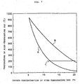
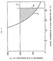
- the inventors investigated, in a waste incinerator, the relationship between the CO and NOx generated in a combustion chamber, and the oxygen concentration and temperature of high-temperature gas blown into the combustion chamber. As a result, it was found that CO and NOx in the exhaust gas reduce at the same time, in case that the oxygen concentration in the high-temperature gas and the temperature of the high-temperature gas are controlled so as to be within a region bounded by line A, line B, and line C as shown in Fig.2.
- Blowing the high-temperature gas into the combustion chamber makes it possible for the waste to be heated by heat radiation from the high-temperature gas and by the sensible heat, and makes it possible to facilitate the thermal decomposition of the waste.
- the high-temperature gas has the oxygen concentration and the temperatures in the region bounded by the line A, the line B, and the line C.
- a stagnation region is formed, where combustible gas and combustion air is remaining in a room above the waste.
- the formed region enables the flame to keep stable and to exist steadily.
- mixing the combustible gas with the combustion air is promoted, to facilitate uniform and stable combustion, so that the generated amount of the NOx and CO reduces to a great extent.
- the oxygen amount is insufficient, and a low temperature of the blown gas causes the combustion of the combustible gas to be unstable, resulting in increasing the generated amount of CO.
- the temperature of the high-temperature gas that attains both low value of NOx and low value of CO is fallen within a range of 280 to 500°C.
- the temperature of the high-temperature gas that attains both low value of NOx and low value of CO is fallen within a range of 200 to 330°C.
- a room in which the temperature is 400°C or higher and the combustible gas exists is a region for decomposing the waste thermally promotes, or the room is the region for decomposing the waste thermally completes. And the region for generating the combustible gas by decomposing the waste thermally and the region where the flame exists.
- paper refuse begins to decompose thermally at about 250°C, the and ends up decomposing at about 400°C.
- Plastic refuse the begins to decompose thermally at about 400°C and ends up decomposing at about 500°C.
- the region for blowing the high-temperature gas exists, preferably as a room in which the room temperature is 400°C or higher and the combustible gas exists.
- the high-temperature gas is preferable to be blown into a region in which a lot of combustible gas exists.
- the region in which a lot of combustible gas exists is fallen within a range, which is, from the region for starting combustion to the main combustion region.
- a region for starting combustion means one, in which decomposing thermally or oxidizing partially enables the waste to generate the combustible gas, and in which the waste starts burning.
- a main combustion region is defined as one, in which decomposing the waste thermally, oxidizing the waste partially and burning the waste are done, simultaneously with generating the combustible gas and with burning the waste with flame. And the main combustion region ends up until the point at which the combustion with the flames completes. (A Burn-off point). Therefore, the region for blowing the high-temperature gas is preferably fallenwithin a range from the region for starting combustion to the main combustion region.
- the region for starting combustion is a room, which is located above a drying stoker, and the main combustion region corresponds to a room, which is located above a burning stoker.
- the term "primary combustion air” is defined as combustion air that is blown from a wind box under a stoker in case of the stoker incinerator, and from a wind box under a fluidized bed in case of the fluidized bed incinerator.
- the amount of the high-temperature blown gas is preferable to be 10 to 70% as much as the amount of the primary combustion air for the reason described below.
- the high-temperature gas does not have a momentum enough to agitate the in-furnace gas. Consequently, it may be a case, it brings up unsatisfactory effects to blow the high-temperature gas.
- the amount of the primary combustion air used as a reference value for the amount of high-temperature blown gas is smaller than the theoretical amount of the theoretical air, which is required for completing the combustion of the waste
- the amount of the high-temperature blown gas is preferably 10 to 70% as much as the amount of theoretical air for burning the waste.
- the amount of the theoretical air is determined from the viewpoint of the properties that the waste possesses.
- the combustible gas generated from the waste usually flows upward. Therefore, in case that the direction in which the high-temperature gas is blown into in the upward direction, the respective flows of the combustible gas and the high-temperature gas have the respective velocity component in the same direction. As a result, agitating and remaining invites less effect on the combustible gas. It becomes less effect on the waste to blow the high-temperature gas. Contrarily, in case that the high-temperature gas is blown into in the horizontal direction or the downward one, it becomes easy for the rising combustible gas to mix well with the high-temperature gas. Furthermore, it becomes easy for the flow of combustible gas to remain, so blowing the high-temperature gas enhances the effects.
- Blowing the high-temperature gas as a swirl flow makes it possible to enhance the effects by mixing. And such blowing makes it possible to enhance the effects by blowing the high-temperature gas.
- "blowing high-temperature gas as a swirl flow” is defined as follows. That is, it may be a case, the high-temperature gas itself, which flows out of an opening for blowing out the gas forms a swirl flow. And, it may be a case, a plurality of the high-temperature gas, which flow out of a plurality of the opening for blowing out the gas, are combined into a swirl flow.
- a method for operating a waste incinerator can easily realize, making use of a stoker-type waste incinerator or a fluidized bed-type one.
- Such an incinerator has equipment for circulating an exhaust gas, which means, for blowing the exhaust gas into the furnace while circulating.
- the air is mixed with the exhaust gas to regulate the properties of the high-temperature gas, and the device controls the oxygen concentration and the temperature of the high-temperature gas that is blown into the range that exists from the region for starting combustion to the main combustion region in the furnace.
- combustion chamber height is defined as a height of a room in which the main combustion is done. That is, a height has a distance from the stoker or the fluidized bed to the ceiling, or the height has a distance from the stoker or the fluidized bed to a position at which the secondary combustion air is blown.
- Fig.3 shows one example of the waste incinerators, in accordance with the present invention.
- a hopper 2 On one side (left-hand side in Fig. 3) of a combustion chamber 1, a hopper 2 is located to charge waste 3 into the combustion chamber 1. At the bottom of the combustion chamber 1, a stoker for burning the waste 3, simultaneously with moving the waste, is located. The stoker inclines downward in accordance with the distance from the hopper 2. The stoker has two different step, which are formed in the furnace. And the stoker is divided into three stages. Such three stages, which is respectively constituted with the stoker, are named for a drying stoker 4, for a burning stoker 5, and for an after burning stoker 6 from the hopper side. On the drying stoker 4, drying and igniting the waste 3 are mainly done.
- burning the waste 3 is mainly done. On such a burning stoker 5, the waste 3 burns to be decomposed thermally, resulting in generating the combustible gas together with the combustion gas. On the burning stoker 5, burning the waste 3 completes substantially. On the after burning stoker 6, the unburned combustibles in the waste 3 that remains in the waste 3 to a slight extent completes burning. Acombustion residue after the complete combustion is discharged through a main ash chute 7.
- a windbox 8 which is connected with a supply pipe for supplying combustion air, is located.
- a main flue 9 and a bypass flue 10 are located at the lower and upper parts of the combustion chamber 1, where the combustion chamber 1 is located on the opposite side of the hopper 2, a main flue 9 and a bypass flue 10 are located. Such flues are connected with a secondary combustion chamber 12 of a waste heat boiler 11, which has a role as a part of gas cooling equipment.
- a barrier (intermediate ceiling) 13 for dividing the combustion gas is located near the outlet of the combustion chamber 1. The barrier (intermediate ceiling) 13 separates the flow of the combustion gas into the main flue 9 and the bypass flue 10.
- the waste 3 is charged into the combustion chamber 1 through the hopper 2, and the waste 3 is dried. And then, the waste burns, simultaneously with supplying the combustion air to the waste 3 and simultaneously with moving the waste on the stokers through the respective supply pipes and the respective wind boxes 8.
- Nozzles 14 are located in the sidewalls of the combustion chamber 1. From such nozzles 14, the high temperature gas, whose temperature is 200°C or higher and satisfies the above-described equation (1) , is blown into the combustion chamber 1. The nozzles 14 are located above the drying stoker 4 and above the left-hand side of the burning stoker 5. When incinerating the waste 3, water evaporates first and then thermal decomposition/partial oxidation takes place. Such a thermal decomposition begins at a temperature of approximately 200°C, and almost finishes at a temperature of approximately 400°C.
- the nozzles 14 are located at a part (rear stage part) of the drying stoker 4 and at a front stage part of the burning stoker 5 to blow the high-temperature gas.
- the thermal decomposition finishes at a much higher temperature, being influenced by a kind of the waste 3.
- it is preferable that the nozzles 14 is also located on the rear stage side (right-hand side in Figure 3) of the position shown in Fig.3.
- the nozzles 14 are preferably located at a height position, not exceeding 1/2 as high as the whole height of the combustion chamber.
- the nozzles may be located in the portions of the sidewall, the ceiling, the intermediate ceiling 13, or the inlet of the secondary combustion chamber 12. Such nozzles have roles for blowing the high-temperature gas into a region, where the main flue gas mixes with the bypass flue gas that contains a lot of combustible gas. That is, for blowing the high-temperature gas into an inlet portion of the secondary combustion chamber 12 above the intermediate ceiling 13.
- the amount of the high-temperature blown gas is as small as possible, taking an exhaust gas treatment and the like into consideration.
- the amount of the blown gas is preferably 10 to 70% as much as the amount of the primary air blown from the wind box 8.
- the amount of the blown gas is controlled so as to be fallen within a range of 10 to 70% as much as the amount of the primary air, simultaneously with monitoring the amount of the exhausted CO and NOx.
- the kind of the waste 3 influences on the amount of the blown primary air, that is, the amount of the blown primary air is smaller than the theoretical air amount necessary for burning the waste 3.
- the amount of the high-temperature blown gas may be, as described above, within a range of 10 to 70% as much as the theoretical air amount necessary for burning the waste 3.
- the nozzles 14 are located in the horizontal direction or in the downward one , the high-temperature gas inj ected from the nozzles causes the flow of the combustible gas to remain against the rising flow. And such remaining enhances the combustible gas to burn. From the standing point of the effects by promoting remaining, the nozzles are preferably located in the downward direction. However, in case that a downward angle of the nozzles is too large, it makes impossible for the high-temperature gas to reach the whole of the furnace along a width direction. Therefore, the downward angle is particularly preferable, fallen within a range of 10 to 20°, downward from the horizontal direction.
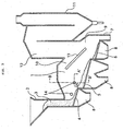
- Fig. 4A-4C show a sectional view along the line A-A' of Fig. 3 (horizontal cross section: Fig.4A and 4B) and a sectional view along the line B-B' of Fig.3 (vertical cross section:Fig.4C), in order to show the allocation of the nozzles in Fig. 3.
- Fig.4A-4C omit the structures that have no relation with the present invention.
- Fig.4A high-temperature gases 19 are injected from a pair of nozzles 14 provided in a furnace wall 17 so as to be opposed to each other in the width direction, and collide with each other in the center of furnace. Therefore, in the central portion of the furnace, the in-furnace gas is slow to move, and a stagnation region 15 is formed, where the gas remains. As a result, a stable combustion is done.
- Fig.4B shows another example.
- the respective directions of the nozzles 14 are located in such a way that the center axes are parallel each other and separated at a predetermined interval, so that in the central portion of the furnace, the mutual high-temperature gas 19 passes by each other, apart from a predetermined distance. Therefore, a swirl region 20 is formed in the central portion of the furnace.
- the stagnation region 15 or the swirl region 20 is formed in the central portion of the furnace in a plain view. Therefore, as described above, the flame keeps stable to promote mixing of the mutual gas.
- Fig.4A shows how to control the size of the stagnation region 15, changing the flow velocities of the high-temperature gas injected from the two nozzles 14 in the same way. Furthermore, the difference makes it possible to change the transverse position in the furnace, where the stagnation region 15 is formed.
- the difference means the one in the flow velocity between one high-temperature gas injected from one side of the nozzles 14 and the other high-temperature gas injected from the other side of the nozzles 14.
- changing the directions of the nozzles 14 in the lengthwise direction of the furnace in the same direction makes it possible to change the longitudinal position in the furnace of the stagnation region 15.
- Fig.4C is a vertically sectional view of the furnace.
- the Fig.4C shows a state to form the stagnation region 15.
- the high-temperature gas 19 is blown from the nozzles 14, which is located slantwise downward on both sides in the furnace walls 17.
- the high-temperature gas 19 collides with the rising combustible gas 21 to form the stagnation region 15.
- a stable combustion is done in the stagnation region 15.
- a stable flame is formed.
- unstable combustion which happens in the region for starting the combustion, is not amplified, even at a low air excess ratio. Consequently, it prevents the soot and the like from generating, resulting in the uniform and the stable combustion.
- blowing the high-temperature gas has an effect on stabilizing the combustion, so as to agitate the gas near the sidewall of the furnace sufficiently. Therefore, it is preferable to keep the blowing speed as at least 10m/s or more.
- the flame in the furnace is a luminous flame when high-temperature gas is not blown. But, in case that the high-temperature gas is blown appropriately into the furnace as described above, the flame in the furnace becomes transparent, so that the stoker is observed from the furnace wall. The reason why such a flame is obtained is that blowing the high-temperature gas makes it possible to burn the combustible gas slowly. Therefore, judging from the viewpoint of the transparency degree of the flame in the furnace, the criterion is applied to the process, concerning whether appropriately or not the high temperature gas is blown into the furnace.
- the above-described embodiment has an effect on reducing the amount of trace hazardous substances such as CO, NOx, and dioxin.
- Fig.3 illustrates a furnace that has the intermediate ceiling 13.
- the present invention is applied to a furnace, which has no intermediate ceiling.
- the high-temperature gas is blown into the combustion chamber 1
- it is applied to the process that the high-temperature gas is blown into the secondary combustion chamber 12.
- the high-temperature gas is blown from one side of the furnace without both sides.
- the high-temperature gas is, also, blown from the intermediate ceiling or the ceiling, although it is applicable from the sidewall of the furnace.
- the circulated exhaust gas is one part of the exhaust gas discharged from the waste incinerator, and has an effect on reducing the amount of the hazardous substances and the exhaust gas by returning the gas into the combustion chamber.
- the circulated exhaust gas is satisfied with the conditions of the high-temperature gas in the present invention, it may be a case, the circulated exhaust gas is blown into the furnace by itself, without mixing.
- the conditions satisfy both which means, the temperature condition is lower than 200°C and the oxygen concentration is low
- it may be a case, high temperature air is produced by high-temperature air producing equipment or by a hot stove, such high-temperature air is mixed with the circulated exhaust gas, and such high-temperature gas is blown into the furnace as the high-temperature gas that satisfy the conditions of the invention.
- the temperature of the exhaust gas from the secondary combustion chamber 12 is sufficiently high and the oxygen concentration is high, such exhaust gas together with air is blown into the furnace. This is done, making use of such exhaust gas instead of the high temperature air, without applying the high-temperature air producing equipment. Furthermore, in case that the temperature of the exhaust gas from the secondary combustion chamber 12 is 200°C or higher, and the relationship between the oxygen concentration and temperature satisfies the above-described equation (1), such exhaust gas is blown directly into the furnace.
- the exhaust gas generating from the incinerator is used as the whole or as the partial amount of the high-temperature gas, sodium salt, potassium salt and the like in dust, which the exhaust gas contains, adhere to the wall of pipes. Consequentlly, there has a possibility to occur the corrosion and to clog the pipes. Furthermore, in case that the exhaust gas is blown into the furnace without removing dust, the danger is predicted that the concentration of the exhausted hazardous substances rather increases by the hazardous substances (for example, dioxin), which is contained in the dust. Therefore, it is preferable that the dust in the exhaust gas is removed. As a method for removing the dust, the filter method and the cyclone method, which are well known to the world, are applicable.
- the filter method has one using a filter cloth and the other using a ceramic filter.
- the ceramic filter is preferable from the viewpoint of the durability and the heat resistance.
- the filter cloth which is fabricated from metallic fibers, is also effective, in such a case, it is influenced by the service temperature.
- a moving bed type dust eliminator is usable. It is preferable that the dust is removed as close as possible to the take-off port, in order to shorten the length of the pipes, which is located between the take-off port and the dust-removing device.
- the incinerator with a waste heat boiler, it is effective to take off the exhaust gas from the boiler.
- the boiler makes it possible to take off the exhaust gas, whose temperature is 800°C. Furthermore, such a high-temperature gas enables high-temperature hazardous substances to be removed effectively.
- high-temperature air producing equipment for example, the equipment, in which air or oxygen is mixed with the combustion gas from a regenerative burner or a combustion burner of a recuperator or a hot stove, is usable.
- the regenerative burner is a device that provides a pair of heat reservoirs. The first heat reservoir is heated by the high-temperature exhaust gas from a combustion burner. And, air is sent into the second heat reservoir that was previously heated, is heated. In the regenerative burner, it is possible to switch over the heating of heat reservoir by the high-temperature exhaust gas and the heating of air by heat reservoir.
- an ejector is preferably used for mixing the gas with the air and for blowing into the furnace. That is to say, the high-temperature gas is introduced into the ejector, and is used as a driving flow for mixing with the circulated exhaust gas, simultaneously with sucking, and the mixed gas is blown into the furnace.
- Such a device makes it possible to require no special movable section such as a fan for sucking the circulated exhaust gas, so that the system configuration becomes simple. And, there becomes much less possibility to invite dust trouble.
- Table 1 shows the countermeasures taken by the operational factors and by the operational method, in order to improve the characteristic of the high-temperature gas that is blown into the furnace.
- Such countermeasures are taken, in case that burner combustion gas from the hot stove, diluted air, and circulated exhaust gas are mixed together for preparing the high-temperature gas to be blown into the furnace.
- such countermeasures are taken, in case that the characteristic of the high-temperature gas blown into the furnace (oxygen concentration and temperature) is fallen without a range of the present invention.
- the oxygen concentration is lower than the range of the present invention and in case that the temperature is higher than the range of the present invention, the amount of the diluted air is forced to increase, the following countermeasure is taken.
- the amount of the combustion burner is forced to increase in order to rise the temperature of the high-temperature gas.
- the amount of the circulated gas is forced to decrease, simultaneously with increasing the amount of the diluted air (the amount of the air mixed into the high-temperature gas). Consequently, the results of the countermeasures become to be fallen within a conditional range that the present invention satisfies.
- the oxygen concentration is lower than the range of the present invention, and in case that the temperature is higher than the range of the present invention, merely the amount of the diluted air is forced to increase, resulting in increasing the oxygen concentration.
- the example was shown, in which the high-temperature gas is blown so as to form the stagnation region or the swirl region in the furnace.
- the object of the present invention is stabilizing combustion in the range from the region for starting the combustion to the main combustion region. So, in case that the temperature and the oxygen concentration of the high-temperature gas is fallen within the range of the present invention, the high-temperature gas are not always necessary to be blown so as to form the stagnation region or the swirl region.
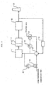
- Fig.5 shows one example of the exhaust gas circulation systems in the waste incinerator, in accordance with the present invention.
- Fig. 5 shows in detail, the exhaust gas from the combustion chamber 1 is introduced into the waste heat boiler 11, and subj ected to secondary combustion in the secondary combustion chamber 12, which is a part of the waste heat boiler 11. Thereafter, the heat that the gas holds is exchanged by the waste heat boiler 11, the gas is purified by exhaust gas treating equipment 22, and the gas is discharged into atmospheric air through a stack 23.
- a part of the exhaust gas is sucked by a blower 24 from the downstream side of the exhaust gas treating equipment, and is introduced into a gas mixer 25.
- the high-temperature combustion gas such as burner combustion gas is introduced into the gas mixer 25 via a high-temperature combustion gas regulating valve 26, simultaneously with introducing the diluted air into the gas mixer 25 via a diluted air regulating valve 27.
- the exhaust gas, the high-temperature combustion gas, and the diluted air are mixed together in order to prepare the high-temperature gas.
- the high-temperature gas is blown into the combustion chamber 1.
- An oxygen concentration controller 29 controls the oxygen concentration in the high-temperature gas.
- the opening of the diluted air regulating valve 27 is regulated so that the oxygen concentration in the high-temperature gas keep a predetermined value. Furthermore, a temperature controller 28 controls the temperature of the high-temperature gas. In the temperature controller 28, the opening of the high-temperature combustion gas-regulating valve 26 is regulated so that the temperature of the high-temperature gas exists within the range shown by the above-described equation (1).
- the process has a function for controlling the oxygen concentration and the temperature in the high-temperature gas blown into the combustion chamber. So, the oxygen concentration and the temperature in the high-temperature gas blown into the combustion chamber are kept in an appropriate range. In case that it is desired to regulate the flow rate or the flow velocity of the high-temperature gas being blown, the rotational speed of the blower 24 has only to be controlled.
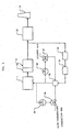
- Fig. 6 shows another example of the exhaust gas circulation systems shown in Fig. 5.
- the example is different from the example shown in Fig. 5, merely from the viewpoint of the position, which is, an outlet of the waste heat boiler 11, where the exhaust gas is taken off.
- the exhaust gas is taken off from the rear of the exhaust gas treating equipment 22, the dust in the exhaust gas is removed, and the exhaust gas becomes clean.
- the temperature of the exhaust gas remains as a decreased one.
- the exhaust gas is taken off from the outlet of the waste heat boiler 11. Therefore, the temperature of the exhaust gas is high. However, the exhaust gas contains the dust. Therefore, the exhaust gas is sent to the blower 24 after a dust eliminator 30, located in a pipe running to the blower 24 removes the dust.
- the high-temperature combustion gas such as the burner combustion gas and the diluted air are mixed with the circulated exhaust gas.
- the high-temperature air produced by the above-described high-temperature air manufacturing equipment is also be introduced into a gas combustor, instead of the high-temperature combustion gas.
- the amount of air introduced into the high-temperature air manufacturing equipment is also regulated to control the oxygen concentration in the high-temperature gas.
- the inventors also found out an effective method for operating a waste incinerator. That is, it is effective to contain at least one of carbon dioxide and water vapor in the high-temperature gas, in order to sufficiently reduce hazardous substances such as NOx and CO, when the high-temperature gas is blown into the combustion chamber.
- the reason why such a method is effective is that stable combustion is done, even in case that the combustion is done at a low air excess ratio.
- the waste and the combustible gas generating from the waste are heated efficiently by the heat radiation from the high-temperature gas, which contains such gas
- the temperature of the high-temperature gas, which attains both of low-NOx and low-CO is fallen within a range of 200 to 550°C.
- the temperature of the high-temperature gas, which attains both of low-NOx and low-CO is fallen within a range of 200 to 400°C.
- a region, in which the high-temperature gas is blown is a room, where the temperature is 400°C or higher and where the combustible gas exists. And the region is preferably a range that falls within from the one for starting the combustion to the main combustion one.
- the configuration of the waste incinerator includes a usable waste heat boiler
- high-temperature gas contains the gas introduced from the passage of the waste heat boiler or from the outlet of the waste heat boiler
- the sensible heat in the exhaust gas is utilized effectively. Consequently, the thermal efficiency increases.
- the configuration of the waste incinerator includes an exhaust gas treating equipment
- the high-temperature gas whose temperature is 800°C or lower and which is introduced from the upstream side of the exhaust gas treating equipment
- the sensible heat in the exhaust gas is utilized effectively, similarly mentioned above. Consequently, the thermal efficiency increases.
- the method for operating the waste incinerator in accordance with the present invention realizes the waste incinerator such as Fig.3, which has been described above.
- the contents of embodiment 1 are applicable, except the following situation. These are, the high-temperature gas is blown into the combustion chamber 1 through the nozzles 14 provided in the side walls of the combustion chamber 1, where the gas contains at least one of carbon dioxide and water vapor, the gas has a temperature of 200°C or higher, and the gas satisfies the above-described equation (2).
- Embodiments 1 and 2 showed that the temperature of high-temperature gas blown into the combustion chamber is 200°C or higher. Even furthermore, the inventors found out that there are conditions that suppress the amount of the generating CO and dioxin, even in case that the temperature is lower than 200°C.
- the thermal decomposition begins, in general, at the temperature of 100°C or higher, so that even in case that the temperature is lower than 200°C, the thermal decomposition happens, and the combustible gas generates. Therefore, under the condition that the temperature and the oxygen concentration of the high-temperature gas are adequate, it brings up an effect to reduce CO and dioxin. In such a case, the effect on reducing NOx is smaller than that of the case where the high-temperature gas has a temperature of 200°C or higher. But, it may be a case, a NOx removal system makes it possible to reduce NOx value.
- Fig.8 shows the relationship between the temperature and the oxygen concentration of the high-temperature gas. It was found out clearly that the following conditions make it possible to promote the thermal composition of the waste andmake it possible to keep the stable flame on the layer of the waste. These are to say, by blowing the high-temperature gas having the oxygen concentration and the temperature in a region bounded by the line A, the line B, and the line C, the conditions satisfy that the temperature of the high-temperature gas is lower than 200°C, simultaneously with satisfying the above-described equation (3).
- the combustible gas promotes to be mixed burning (so-called mixed combustion) at the same time, so that uniform and stable combustion is done, resulting in reducing the generation of hazardous substances such as CO and dioxin.
- the reason why the oxygen concentration is 21% or lower is that an oxygen concentration exceeding 21% requires oxygen enrichment equipment. So, it is not preferable.
- the temperature of the high-temperature gas is lower than 200°C as well as embodiment 2, it is effective to force the high-temperature gas to contain at least one of carbon dioxide and water vapor in the high-temperature gas, in order to suppress the generation of CO and dioxin.
- Fig. 9 shows that the temperature and oxygen concentration of the high-temperature gas are controlled so as to be in a region bounded by the line D, the line E, and the line F. That is to say, it becomes necessary that the temperature of the high-temperature gas is lower than 200°C and satisfies the above-described equation (4).
- the description in embodiment 1 is applicable, except the conditions for the high-temperature blown gas.
Landscapes
- Engineering & Computer Science (AREA)
- Mechanical Engineering (AREA)
- General Engineering & Computer Science (AREA)
- Incineration Of Waste (AREA)
Applications Claiming Priority (9)
| Application Number | Priority Date | Filing Date | Title |
|---|---|---|---|
| JP2002130526 | 2002-05-02 | ||
| JP2002130526 | 2002-05-02 | ||
| JP2002237023A JP3989333B2 (ja) | 2002-08-15 | 2002-08-15 | 廃棄物焼却炉の操業方法 |
| JP2002237022A JP3995237B2 (ja) | 2002-05-02 | 2002-08-15 | 廃棄物焼却炉の操業方法 |
| JP2002237024 | 2002-08-15 | ||
| JP2002237023 | 2002-08-15 | ||
| JP2002237024A JP2004077014A (ja) | 2002-08-15 | 2002-08-15 | 廃棄物焼却炉の操業方法 |
| JP2002237022 | 2002-08-15 | ||
| PCT/JP2003/002623 WO2003093728A1 (en) | 2002-05-02 | 2003-03-06 | Method of operating waste incinerator and waste incinerator |
Publications (2)
| Publication Number | Publication Date |
|---|---|
| EP1500875A1 true EP1500875A1 (de) | 2005-01-26 |
| EP1500875A4 EP1500875A4 (de) | 2007-07-11 |
Family
ID=29407970
Family Applications (1)
| Application Number | Title | Priority Date | Filing Date |
|---|---|---|---|
| EP03710255A Withdrawn EP1500875A4 (de) | 2002-05-02 | 2003-03-06 | Verfahren zum betrieb einer abfallverbrennungsanlage und abfallverbrennungsanlage |
Country Status (3)
| Country | Link |
|---|---|
| EP (1) | EP1500875A4 (de) |
| KR (1) | KR100660757B1 (de) |
| WO (1) | WO2003093728A1 (de) |
Cited By (1)
| Publication number | Priority date | Publication date | Assignee | Title |
|---|---|---|---|---|
| CN105351944A (zh) * | 2015-12-10 | 2016-02-24 | 重庆三峰卡万塔环境产业有限公司 | 一种改进的炉排炉垃圾焚烧装置 |
Families Citing this family (2)
| Publication number | Priority date | Publication date | Assignee | Title |
|---|---|---|---|---|
| KR101175296B1 (ko) * | 2010-04-02 | 2012-08-20 | 이승우 | 폐기물 소각장치 |
| KR101436067B1 (ko) * | 2014-04-08 | 2014-09-12 | (주)씨엠환경에너지 | 배출가스를 이용한 연소제어 기술이 내재된 소각로 |
Family Cites Families (6)
| Publication number | Priority date | Publication date | Assignee | Title |
|---|---|---|---|---|
| JPS62182516A (ja) * | 1986-02-05 | 1987-08-10 | Ishikawajima Harima Heavy Ind Co Ltd | 流動床式焼却炉の燃焼方法 |
| US5044287A (en) * | 1989-06-16 | 1991-09-03 | Ebara Corporation | Method of controlling combustion in a fluidized bed furnace |
| JP2719452B2 (ja) * | 1991-02-28 | 1998-02-25 | 株式会社神戸製鋼所 | 流動床式焼却炉における燃焼用空気の供給方法及びその装置 |
| JPH0517311U (ja) * | 1991-08-16 | 1993-03-05 | 石川島播磨重工業株式会社 | デイーゼル機関のNOx低減装置 |
| JP2001241629A (ja) * | 2000-03-01 | 2001-09-07 | Mitsubishi Heavy Ind Ltd | 廃棄物低公害燃焼装置 |
| JP2002228130A (ja) * | 2001-02-01 | 2002-08-14 | Mitsubishi Heavy Ind Ltd | 燃焼炉若しくは焼却炉、及びこれらの炉の排出ガス規制分低減方法 |
-
2003
- 2003-03-06 KR KR1020047017549A patent/KR100660757B1/ko not_active Expired - Fee Related
- 2003-03-06 EP EP03710255A patent/EP1500875A4/de not_active Withdrawn
- 2003-03-06 WO PCT/JP2003/002623 patent/WO2003093728A1/ja not_active Ceased
Cited By (1)
| Publication number | Priority date | Publication date | Assignee | Title |
|---|---|---|---|---|
| CN105351944A (zh) * | 2015-12-10 | 2016-02-24 | 重庆三峰卡万塔环境产业有限公司 | 一种改进的炉排炉垃圾焚烧装置 |
Also Published As
| Publication number | Publication date |
|---|---|
| KR100660757B1 (ko) | 2006-12-26 |
| EP1500875A4 (de) | 2007-07-11 |
| WO2003093728A1 (en) | 2003-11-13 |
| KR20040102200A (ko) | 2004-12-03 |
Similar Documents
| Publication | Publication Date | Title |
|---|---|---|
| KR100705204B1 (ko) | 화격자식(火格子式) 폐기물 소각로 및 그 연소 제어방법 | |
| EP3193084B1 (de) | Stoker-verbrennungsanlage | |
| JP6824642B2 (ja) | 廃棄物焼却装置及び廃棄物焼却方法 | |
| JP2004084981A (ja) | 廃棄物焼却炉 | |
| JP5861880B2 (ja) | 廃棄物焼却炉及び廃棄物焼却方法 | |
| JP7035356B2 (ja) | 廃棄物焼却装置及び廃棄物焼却方法 | |
| JP6218117B2 (ja) | 火格子式廃棄物焼却炉及び廃棄物焼却方法 | |
| JP3956862B2 (ja) | 廃棄物焼却炉の燃焼制御方法及び廃棄物焼却炉 | |
| JP3989333B2 (ja) | 廃棄物焼却炉の操業方法 | |
| CN104160214B (zh) | 炉排式废弃物焚烧炉以及废弃物焚烧方法 | |
| JP6256859B2 (ja) | 廃棄物焼却方法 | |
| JP2005226970A (ja) | 火格子式廃棄物焼却炉及びその操業方法 | |
| EP1500875A1 (de) | Verfahren zum betrieb einer abfallverbrennungsanlage und abfallverbrennungsanlage | |
| JP2870675B2 (ja) | 熱分解性燃焼帯域の操業方法 | |
| JP6090578B2 (ja) | 廃棄物焼却炉及び廃棄物焼却方法 | |
| JP2642568B2 (ja) | ごみ焼却炉の二次燃焼方法 | |
| JP2001241629A (ja) | 廃棄物低公害燃焼装置 | |
| JP3995237B2 (ja) | 廃棄物焼却炉の操業方法 | |
| JP2004163009A (ja) | 廃棄物焼却システムの操業方法及び廃棄物焼却システム | |
| JP2004169955A (ja) | 廃棄物焼却炉及びその操業方法 | |
| JP6183787B2 (ja) | 火格子式廃棄物焼却炉及び廃棄物焼却方法 | |
| JP2019190729A (ja) | 廃棄物焼却装置及び廃棄物焼却方法 | |
| JP2004077014A (ja) | 廃棄物焼却炉の操業方法 | |
| JP3014953B2 (ja) | 焼却炉 | |
| JP6103471B2 (ja) | 廃棄物焼却炉及び廃棄物焼却方法 |
Legal Events
| Date | Code | Title | Description |
|---|---|---|---|
| PUAI | Public reference made under article 153(3) epc to a published international application that has entered the european phase |
Free format text: ORIGINAL CODE: 0009012 |
|
| 17P | Request for examination filed |
Effective date: 20041001 |
|
| AK | Designated contracting states |
Kind code of ref document: A1 Designated state(s): AT BE BG CH CY CZ DE DK EE ES FI FR GB GR HU IE IT LI LU MC NL PT RO SE SI SK TR |
|
| AX | Request for extension of the european patent |
Extension state: AL LT LV MK |
|
| DAX | Request for extension of the european patent (deleted) | ||
| RBV | Designated contracting states (corrected) |
Designated state(s): DE FR GB |
|
| A4 | Supplementary search report drawn up and despatched |
Effective date: 20070611 |
|
| RIC1 | Information provided on ipc code assigned before grant |
Ipc: F23G 5/50 20060101ALI20070604BHEP Ipc: F23G 5/30 20060101AFI20070604BHEP |
|
| STAA | Information on the status of an ep patent application or granted ep patent |
Free format text: STATUS: THE APPLICATION HAS BEEN WITHDRAWN |
|
| 18W | Application withdrawn |
Effective date: 20071204 |