EP1500874A2 - Brûleur pour dispositif de chauffage pour véhicule - Google Patents
Brûleur pour dispositif de chauffage pour véhicule Download PDFInfo
- Publication number
- EP1500874A2 EP1500874A2 EP04006110A EP04006110A EP1500874A2 EP 1500874 A2 EP1500874 A2 EP 1500874A2 EP 04006110 A EP04006110 A EP 04006110A EP 04006110 A EP04006110 A EP 04006110A EP 1500874 A2 EP1500874 A2 EP 1500874A2
- Authority
- EP
- European Patent Office
- Prior art keywords
- combustion air
- combustion
- air supply
- combustion chamber
- burner
- Prior art date
- Legal status (The legal status is an assumption and is not a legal conclusion. Google has not performed a legal analysis and makes no representation as to the accuracy of the status listed.)
- Granted
Links
- 238000010438 heat treatment Methods 0.000 title description 2
- 238000002485 combustion reaction Methods 0.000 claims abstract description 187
- 230000002093 peripheral effect Effects 0.000 claims description 7
- 210000000056 organ Anatomy 0.000 claims description 2
- 239000000446 fuel Substances 0.000 description 8
- 239000003344 environmental pollutant Substances 0.000 description 5
- 231100000719 pollutant Toxicity 0.000 description 5
- 230000000977 initiatory effect Effects 0.000 description 2
- 230000000712 assembly Effects 0.000 description 1
- 238000000429 assembly Methods 0.000 description 1
- 230000015572 biosynthetic process Effects 0.000 description 1
- 238000004140 cleaning Methods 0.000 description 1
- 230000000295 complement effect Effects 0.000 description 1
- 230000006735 deficit Effects 0.000 description 1
- 230000008021 deposition Effects 0.000 description 1
- 230000008020 evaporation Effects 0.000 description 1
- 238000001704 evaporation Methods 0.000 description 1
- 230000003993 interaction Effects 0.000 description 1
- 239000007788 liquid Substances 0.000 description 1
- 239000000203 mixture Substances 0.000 description 1
- 239000002245 particle Substances 0.000 description 1
- 238000000638 solvent extraction Methods 0.000 description 1
- 239000004071 soot Substances 0.000 description 1
Images
Classifications
-
- F—MECHANICAL ENGINEERING; LIGHTING; HEATING; WEAPONS; BLASTING
- F23—COMBUSTION APPARATUS; COMBUSTION PROCESSES
- F23L—SUPPLYING AIR OR NON-COMBUSTIBLE LIQUIDS OR GASES TO COMBUSTION APPARATUS IN GENERAL ; VALVES OR DAMPERS SPECIALLY ADAPTED FOR CONTROLLING AIR SUPPLY OR DRAUGHT IN COMBUSTION APPARATUS; INDUCING DRAUGHT IN COMBUSTION APPARATUS; TOPS FOR CHIMNEYS OR VENTILATING SHAFTS; TERMINALS FOR FLUES
- F23L15/00—Heating of air supplied for combustion
- F23L15/04—Arrangements of recuperators
-
- F—MECHANICAL ENGINEERING; LIGHTING; HEATING; WEAPONS; BLASTING
- F23—COMBUSTION APPARATUS; COMBUSTION PROCESSES
- F23C—METHODS OR APPARATUS FOR COMBUSTION USING FLUID FUEL OR SOLID FUEL SUSPENDED IN A CARRIER GAS OR AIR
- F23C7/00—Combustion apparatus characterised by arrangements for air supply
- F23C7/02—Disposition of air supply not passing through burner
- F23C7/06—Disposition of air supply not passing through burner for heating the incoming air
-
- F—MECHANICAL ENGINEERING; LIGHTING; HEATING; WEAPONS; BLASTING
- F23—COMBUSTION APPARATUS; COMBUSTION PROCESSES
- F23D—BURNERS
- F23D3/00—Burners using capillary action
- F23D3/40—Burners using capillary action the capillary action taking place in one or more rigid porous bodies
-
- Y—GENERAL TAGGING OF NEW TECHNOLOGICAL DEVELOPMENTS; GENERAL TAGGING OF CROSS-SECTIONAL TECHNOLOGIES SPANNING OVER SEVERAL SECTIONS OF THE IPC; TECHNICAL SUBJECTS COVERED BY FORMER USPC CROSS-REFERENCE ART COLLECTIONS [XRACs] AND DIGESTS
- Y02—TECHNOLOGIES OR APPLICATIONS FOR MITIGATION OR ADAPTATION AGAINST CLIMATE CHANGE
- Y02E—REDUCTION OF GREENHOUSE GAS [GHG] EMISSIONS, RELATED TO ENERGY GENERATION, TRANSMISSION OR DISTRIBUTION
- Y02E20/00—Combustion technologies with mitigation potential
- Y02E20/34—Indirect CO2mitigation, i.e. by acting on non CO2directly related matters of the process, e.g. pre-heating or heat recovery
Definitions
- the present invention relates to a burner assembly for a vehicle heater, comprising a combustion chamber and a Verbrennungs Kunststoffzu 1500an extract for introducing combustion air into the combustion chamber.
- a burner assembly for a vehicle heater comprising a combustion chamber and a Verbrennungs Kunststoffzu 1500an instructing combustion air into the Combustion chamber, wherein the Verbrennungs Kunststoffzu 1500an extract a combustion air heat exchanger assembly for transmitting in case of combustion arising heat on at least part of the in the combustion chamber includes combustion air to be introduced.
- the Combustion air heat exchanger arrangement one of the to be heated Combustion air permeable and from the combustion products at least partially flow around the combustion air flow space includes.
- the combustion air flow space involving a combustion product flow direction arranged downstream of the combustion chamber Flammblende is limited.
- the Combustion air flow space in cooperation with a combustion product flow direction arranged downstream of the combustion chamber Flame tube is limited, wherein it may preferably be provided that the flame tube is formed substantially cylindrical and with at least another substantially cylindrical element the combustion air flow space limited.
- a combustion chamber housing be provided, which with an outer circumferential wall and a bottom wall defining the combustion chamber, wherein the combustion air supply arrangement a first combustion air supply area comprising for introducing in the combustion air heat exchanger assembly heated combustion air into the combustion chamber housing.
- the first combustion air supply area a combustion air supply opening in the outer peripheral wall comprises.
- the first combustion air supply area it is possible for the first combustion air supply area to enter into an ignition organ receiving opening opens. This is particularly advantageous because then in the area where the initial ignition occurs is intensified, already heated air is provided, so that also in the starting phase of pollutant emissions can be reduced and also reduced the risk of deposition of combustion residues can be.
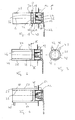
- a burner assembly according to the invention is generally 10 designated.
- This burner assembly 10 includes a combustion chamber housing 12, with an outer wall 14 and a bottom wall 16 a Combustion chamber 18 in the axial direction, so one direction with respect to a Longitudinal axis L of the burner assembly 10, as well as limited radially outward.
- On the outer peripheral wall 14 is at the combustion chamber 18 facing Side provided a porous evaporator medium 20, in which liquid fuel is introduced via a fuel feed line 22 can be to distribute this by capillary action and the combustion chamber 18 to evaporate down.
- combustion air inlet port 24 which has a plurality of combustion air inlet openings 26 has. Through these openings 26 flows a part of the combustion used with the evaporated fuel or required Combustion air, promoted by a combustion air blower, in the Combustion chamber 18.
- the Combustion chamber housing 12 At the axially open side of the combustion chamber 18 is the Combustion chamber housing 12 and theticianimportantswandung 14 thereof with an elongated, substantially cylindrically shaped Flame tube 28 connected.
- a flame shutter 30 is provided, the one central opening 32 for passage of the combustion products.
- combustion air heat exchanger assembly 34 In the burner assembly 10 according to the invention is further a combustion air heat exchanger assembly 34 provided.
- This is in the in Fig. 1 illustrated embodiment formed essentially by the annular member providing the flame shutter 30, and another one complementary annular member 36, which together with the Flame diaphragm 30, for example, concentric with the longitudinal axis L. arranged combustion air flow space 38 with ring-like contour limited.
- About a combustion air inlet 40 is another part of the into the combustion chamber 18 to be introduced combustion air in this combustion air heat exchanger assembly 34 initiated.
- About a combustion air outlet 42 leaves the heated combustion air then the Combustion air heat exchanger assembly 34 and is in the combustion chamber 18 fed.
- combustion air heat exchanger assembly 34 is at least one Part of the air used for combustion preheated, under utilization the self-generated during combustion in the combustion chamber 18 Warmth. So while this combustion air to be heated, the combustion air flow space 38 flows through the combustion products flow around at a comparatively high temperature, this combustion air heat exchanger arrangement 34, so that part of the combustion products transported heat to those in the combustion air flow space flowing air is transferred.
- Burner assembly described in detail as with reference to FIG. 1, so in the following only on the existing differences will be received.
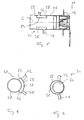
- FIG. 2 shows an embodiment in which the combustion air heat exchanger arrangement 34 also with the help of the flame tube 28 as a combustion air flow space 38 radially outside limiting assembly is formed.
- the flame shutter 30 and a Ring-like termination portion 44 limit the combustion air flow space 38 in the axial direction, while another substantially cylindrical member 46 provides the boundary radially inward.
- a combustion air inlet 40 can again be provided and a combustion air outlet 42 may be provided which in principle can be positioned arbitrary or matching point. It can additionally, a partitioning element in the combustion air flow space 38 48 be provided, which ensures that forcibly a long Flow path from the inlet 40 to the outlet 42 must be flowed through.
- the flame tube is limited 28 the combustion air flow space 38 radially inward, while a additional cylindrical member 50, the flame tube 28 and a part of the Combustor housing 12 radially surrounds the outside and thus also the combustion air flow space 38 bounded radially outward.
- the axial Conclusion is again by a ring-like termination section 52 on the one hand and one provided on the combustion chamber housing 12 radially realized outside flange portion 54 on the other.
- an inlet 40 and an outlet 42 for the to be heated Be provided combustion air the positioning may be so that forcibly by comparatively far apart positioning a long flow path and thus a long interaction path is provided for the combustion air to be heated.
- a variant is shown, in which again a portion of Flame tube 28 the combustion air flow space 38 radially outward while a substantially cylindrical member 54 for the Closing radially inward ensures.
- a substantially cylindrical member 54 for the Closing radially inward may integrally provided two annular end portions 56, 58th be present, which is the axial completion of the combustion air flow space realize.
- Flow through the flame tube 28 with the combustion products is preferably the component 54 with the end portions 56, 58 extending completely annularly about the longitudinal axis L. designed.
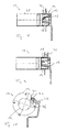
- FIG. 6 shows an embodiment is shown in which the flame tube 28th the combustion air flow space 38 with a portion radially limited inside, while radially outwardly a cylinder segment-like component 58th is provided, which with personnelsendsegmenten 60, 62 and not shown Axialendsegmenten then the combustion air flow space 38th concludes. Because here is a wider impact on the combustion product flow in the flame tube 28 is not present, it is easy possible, only a peripheral segment of the flame tube 28 for heat transfer to use.
- a further cylindrical member 64 is provided, the For example, extending along the entire length of the flame tube 28 is formed, with respect to the flame tube 28 and the longitudinal center axis L is not concentric but eccentric. This results in a correspondingly non-circular ausgestalteter Combustion air flow space 38, but, in the extreme case, a combustion air flow space with sickle-like cross-section.
- baffles or deflection can be provided to to ensure that they flow through and are heated Combustion air must pass through the longest possible flow path.
- FIG. 1 With reference to Fig. 1 has already been described as the heated Combustion air can be introduced into the combustion chamber 18. A Possibility for this is shown in FIG. 8, it being understood that that the combustion air heat exchanger arrangement not shown here may be formed as described above.
- a combustion air inlet port 70 which passes through the outer circumferential wall 14 and, for example, opens into the porous evaporator medium 20 or possibly this also interspersed, so that he to the combustion chamber 18 down is open. While in the variant shown in Fig. 8, the combustion air inlet port 70 close to the flame tube 28 End region of the combustion chamber 18 is provided in that shown in Fig. 8 Variant of the inlet port 70 in the bottom wall 16th near the region of the outer peripheral wall 14 is provided.
- inlet ports 70 distributed may be provided to the heated combustion air or the heated part of the combustion air at defined and, for example be able to initiate uniformly distributed positions in the combustion chamber 18.
- combustion air to be heated separate combustion air blower can be provided to by defined Setting this flow the proportion of heated and not to pretend heated air. Also, the part to be heated the combustion air through which also for the not to be heated combustion air provided fans are promoted, in which case by a valve assembly or adjustable branching arrangement therefor it is ensured that a certain part of the combustion air preheats becomes. Furthermore, it is of course possible by specifying appropriate Flow ranges a fixed ratio of to be heated and not to be heated combustion air.
Landscapes
- Engineering & Computer Science (AREA)
- Chemical & Material Sciences (AREA)
- Combustion & Propulsion (AREA)
- Mechanical Engineering (AREA)
- General Engineering & Computer Science (AREA)
- Physics & Mathematics (AREA)
- Thermal Sciences (AREA)
- Wick-Type Burners And Burners With Porous Materials (AREA)
- Air-Conditioning For Vehicles (AREA)
- Air Supply (AREA)
Applications Claiming Priority (2)
| Application Number | Priority Date | Filing Date | Title |
|---|---|---|---|
| DE10333115 | 2003-07-21 | ||
| DE10333115A DE10333115A1 (de) | 2003-07-21 | 2003-07-21 | Brenneranordnung für ein Fahrzeugheizgerät |
Publications (3)
| Publication Number | Publication Date |
|---|---|
| EP1500874A2 true EP1500874A2 (fr) | 2005-01-26 |
| EP1500874A3 EP1500874A3 (fr) | 2008-11-12 |
| EP1500874B1 EP1500874B1 (fr) | 2009-12-30 |
Family
ID=33482992
Family Applications (1)
| Application Number | Title | Priority Date | Filing Date |
|---|---|---|---|
| EP04006110A Expired - Lifetime EP1500874B1 (fr) | 2003-07-21 | 2004-03-15 | Brûleur pour dispositif de chauffage pour véhicule |
Country Status (2)
| Country | Link |
|---|---|
| EP (1) | EP1500874B1 (fr) |
| DE (2) | DE10333115A1 (fr) |
Families Citing this family (1)
| Publication number | Priority date | Publication date | Assignee | Title |
|---|---|---|---|---|
| GB0813391D0 (en) | 2008-07-22 | 2008-08-27 | Sensitivity Ltd | Radiator |
Citations (1)
| Publication number | Priority date | Publication date | Assignee | Title |
|---|---|---|---|---|
| EP0930462A2 (fr) | 1998-01-15 | 1999-07-21 | Clemm v. Hohenberg, Eberhard | Tube de flammes pour brûleur |
Family Cites Families (5)
| Publication number | Priority date | Publication date | Assignee | Title |
|---|---|---|---|---|
| NL164384C (nl) * | 1969-01-03 | 1980-12-15 | Koninklijke Hoogovens En Staal | Brander voor gasvormige en vloeibare brandstoffen. |
| DE3202938A1 (de) * | 1981-11-06 | 1983-05-19 | Feraton Anstalt, 9494 Schaan | Verfahren und vorrichtung zum erhitzen von verbrennungsluft und brennstoff in heizungsanlagen |
| JPS59219610A (ja) * | 1983-05-26 | 1984-12-11 | Nippon Denso Co Ltd | 超音波霧化式燃焼装置 |
| US4480986A (en) * | 1983-09-14 | 1984-11-06 | Sea-Labs, Inc. | Liquid fuel vaporizing burner |
| DE3516012A1 (de) * | 1985-05-03 | 1986-11-06 | Karl-Heinz 2000 Wedel Francke | Heizgeraet mit einem brenner und einem waermetauscher |
-
2003
- 2003-07-21 DE DE10333115A patent/DE10333115A1/de not_active Withdrawn
-
2004
- 2004-03-15 EP EP04006110A patent/EP1500874B1/fr not_active Expired - Lifetime
- 2004-03-15 DE DE502004010573T patent/DE502004010573D1/de not_active Expired - Lifetime
Patent Citations (1)
| Publication number | Priority date | Publication date | Assignee | Title |
|---|---|---|---|---|
| EP0930462A2 (fr) | 1998-01-15 | 1999-07-21 | Clemm v. Hohenberg, Eberhard | Tube de flammes pour brûleur |
Also Published As
| Publication number | Publication date |
|---|---|
| DE502004010573D1 (de) | 2010-02-11 |
| EP1500874B1 (fr) | 2009-12-30 |
| DE10333115A1 (de) | 2005-03-03 |
| EP1500874A3 (fr) | 2008-11-12 |
Similar Documents
| Publication | Publication Date | Title |
|---|---|---|
| EP1860379B1 (fr) | Composant d'évaporateur, en particulier pour un appareil de chauffage de véhicule ou un dispositif de réformateur de carburant d'un système à cellules combustibles | |
| EP0758959A1 (fr) | Chambre de combustion du bruleur d'un appareil de chauffage pour vehicule ou d'un filtre contre les particules de gaz d'echappement | |
| DE2700671C2 (de) | Blaubrennender Ölbrenner | |
| DE3243395A1 (de) | Verfahren zum betrieb eines vergasungsbrenners | |
| DE2346960A1 (de) | Brennerkopf fuer fluessige brennstoffe | |
| EP0843083B1 (fr) | Préevaporateur de combustible | |
| DE10200524C1 (de) | Brennkammerbaugruppe, insbesondere für ein Fahrzeugheizgerät | |
| EP3663669B1 (fr) | Module de chambre de combustion | |
| DE4442425A1 (de) | Brennkammer eines Brenners für ein Fahrzeugheizgerät oder für einen Abgas-Partikelfilter | |
| DE10255361B3 (de) | Brennkammerbaugruppe für ein Heizgerät, insbesondere Fahrzeugheizgerät | |
| DE2364455C3 (de) | Elektrische Heizvorrichtung | |
| EP1522788B1 (fr) | Brûleur à vaporisation | |
| EP1500874B1 (fr) | Brûleur pour dispositif de chauffage pour véhicule | |
| DE3538201A1 (de) | Verdampfungsbrenner fuer ein mit fluessigem brennstoff betriebenes heizgeraet | |
| EP0515365A1 (fr) | Bruleur a reinjection de gaz combustible pour combustibles coulants | |
| EP1788305B1 (fr) | Ensemble de chambre de combustion pour un brûleur à évaporation | |
| DE102009013664A1 (de) | System zum Einleiten von Kraftstoffen in den Abgasstrang eines Kraftfahrzeugs und Kraftstoffverdampfer hierfür | |
| EP1544543B1 (fr) | Dispositif de chauffage, en particulier dispositif de chauffage pour voiture | |
| EP1918639A2 (fr) | Composant de brûleur | |
| EP0097315B1 (fr) | Dispositif de brûleur à fuel pour fourneaux roulants | |
| DE19521296A1 (de) | Verdampfungsbrenner | |
| EP1363071A1 (fr) | Brûleur pour appareil de chauffage | |
| DE10207953A1 (de) | Heizgerät, insbesondere für ein Fahrzeug | |
| DE68909851T2 (de) | Verbrennungsvorrichtung. | |
| DE643421C (de) | Vorrichtung beispielsweise fuer Brennkraftmaschinen zur Herstellung eines Brenngemisches aus fluessigem, etwa bei 180 bis 200íÒC siedendem Brennstoff und einem gasfoermigen Bestandteil, insbesondere Luft |
Legal Events
| Date | Code | Title | Description |
|---|---|---|---|
| PUAI | Public reference made under article 153(3) epc to a published international application that has entered the european phase |
Free format text: ORIGINAL CODE: 0009012 |
|
| AK | Designated contracting states |
Kind code of ref document: A2 Designated state(s): AT BE BG CH CY CZ DE DK EE ES FI FR GB GR HU IE IT LI LU MC NL PL PT RO SE SI SK TR |
|
| AX | Request for extension of the european patent |
Extension state: AL LT LV MK |
|
| PUAL | Search report despatched |
Free format text: ORIGINAL CODE: 0009013 |
|
| AK | Designated contracting states |
Kind code of ref document: A3 Designated state(s): AT BE BG CH CY CZ DE DK EE ES FI FR GB GR HU IE IT LI LU MC NL PL PT RO SE SI SK TR |
|
| AX | Request for extension of the european patent |
Extension state: AL LT LV MK |
|
| 17P | Request for examination filed |
Effective date: 20090512 |
|
| AKX | Designation fees paid |
Designated state(s): CZ DE FR GB PL SE |
|
| 17Q | First examination report despatched |
Effective date: 20090624 |
|
| GRAP | Despatch of communication of intention to grant a patent |
Free format text: ORIGINAL CODE: EPIDOSNIGR1 |
|
| GRAS | Grant fee paid |
Free format text: ORIGINAL CODE: EPIDOSNIGR3 |
|
| GRAA | (expected) grant |
Free format text: ORIGINAL CODE: 0009210 |
|
| AK | Designated contracting states |
Kind code of ref document: B1 Designated state(s): CZ DE FR GB PL SE |
|
| REG | Reference to a national code |
Ref country code: GB Ref legal event code: FG4D Free format text: NOT ENGLISH |
|
| REF | Corresponds to: |
Ref document number: 502004010573 Country of ref document: DE Date of ref document: 20100211 Kind code of ref document: P |
|
| REG | Reference to a national code |
Ref country code: SE Ref legal event code: TRGR |
|
| PG25 | Lapsed in a contracting state [announced via postgrant information from national office to epo] |
Ref country code: PL Free format text: LAPSE BECAUSE OF FAILURE TO SUBMIT A TRANSLATION OF THE DESCRIPTION OR TO PAY THE FEE WITHIN THE PRESCRIBED TIME-LIMIT Effective date: 20091230 |
|
| PGFP | Annual fee paid to national office [announced via postgrant information from national office to epo] |
Ref country code: FR Payment date: 20100331 Year of fee payment: 7 |
|
| PGFP | Annual fee paid to national office [announced via postgrant information from national office to epo] |
Ref country code: GB Payment date: 20100324 Year of fee payment: 7 |
|
| PG25 | Lapsed in a contracting state [announced via postgrant information from national office to epo] |
Ref country code: CZ Free format text: LAPSE BECAUSE OF FAILURE TO SUBMIT A TRANSLATION OF THE DESCRIPTION OR TO PAY THE FEE WITHIN THE PRESCRIBED TIME-LIMIT Effective date: 20091230 |
|
| PLBE | No opposition filed within time limit |
Free format text: ORIGINAL CODE: 0009261 |
|
| STAA | Information on the status of an ep patent application or granted ep patent |
Free format text: STATUS: NO OPPOSITION FILED WITHIN TIME LIMIT |
|
| PGFP | Annual fee paid to national office [announced via postgrant information from national office to epo] |
Ref country code: SE Payment date: 20100324 Year of fee payment: 7 |
|
| 26N | No opposition filed |
Effective date: 20101001 |
|
| REG | Reference to a national code |
Ref country code: SE Ref legal event code: EUG |
|
| GBPC | Gb: european patent ceased through non-payment of renewal fee |
Effective date: 20110315 |
|
| REG | Reference to a national code |
Ref country code: FR Ref legal event code: ST Effective date: 20111130 |
|
| PG25 | Lapsed in a contracting state [announced via postgrant information from national office to epo] |
Ref country code: FR Free format text: LAPSE BECAUSE OF NON-PAYMENT OF DUE FEES Effective date: 20110331 |
|
| PG25 | Lapsed in a contracting state [announced via postgrant information from national office to epo] |
Ref country code: GB Free format text: LAPSE BECAUSE OF NON-PAYMENT OF DUE FEES Effective date: 20110315 |
|
| PG25 | Lapsed in a contracting state [announced via postgrant information from national office to epo] |
Ref country code: SE Free format text: LAPSE BECAUSE OF NON-PAYMENT OF DUE FEES Effective date: 20110316 |
|
| REG | Reference to a national code |
Ref country code: DE Ref legal event code: R082 Ref document number: 502004010573 Country of ref document: DE Representative=s name: WEICKMANN & WEICKMANN, DE |
|
| REG | Reference to a national code |
Ref country code: DE Ref legal event code: R081 Ref document number: 502004010573 Country of ref document: DE Owner name: EBERSPAECHER CLIMATE CONTROL SYSTEMS GMBH & CO, DE Free format text: FORMER OWNER: J. EBERSPAECHER GMBH & CO. KG, 73730 ESSLINGEN, DE Effective date: 20130607 Ref country code: DE Ref legal event code: R082 Ref document number: 502004010573 Country of ref document: DE Representative=s name: WEICKMANN & WEICKMANN, DE Effective date: 20130607 Ref country code: DE Ref legal event code: R082 Ref document number: 502004010573 Country of ref document: DE Representative=s name: RUTTENSPERGER LACHNIT TROSSIN GOMOLL PATENT- U, DE Effective date: 20130607 |
|
| REG | Reference to a national code |
Ref country code: DE Ref legal event code: R082 Ref document number: 502004010573 Country of ref document: DE Representative=s name: RUTTENSPERGER LACHNIT TROSSIN GOMOLL PATENT- U, DE |
|
| PGFP | Annual fee paid to national office [announced via postgrant information from national office to epo] |
Ref country code: DE Payment date: 20150331 Year of fee payment: 12 |
|
| REG | Reference to a national code |
Ref country code: DE Ref legal event code: R119 Ref document number: 502004010573 Country of ref document: DE |
|
| PG25 | Lapsed in a contracting state [announced via postgrant information from national office to epo] |
Ref country code: DE Free format text: LAPSE BECAUSE OF NON-PAYMENT OF DUE FEES Effective date: 20161001 |