EP1500870A1 - Solarbetriebene Leuchte - Google Patents
Solarbetriebene Leuchte Download PDFInfo
- Publication number
- EP1500870A1 EP1500870A1 EP04012171A EP04012171A EP1500870A1 EP 1500870 A1 EP1500870 A1 EP 1500870A1 EP 04012171 A EP04012171 A EP 04012171A EP 04012171 A EP04012171 A EP 04012171A EP 1500870 A1 EP1500870 A1 EP 1500870A1
- Authority
- EP
- European Patent Office
- Prior art keywords
- light source
- holder
- solar
- solar cell
- luminaire according
- Prior art date
- Legal status (The legal status is an assumption and is not a legal conclusion. Google has not performed a legal analysis and makes no representation as to the accuracy of the status listed.)
- Granted
Links
- 230000000694 effects Effects 0.000 description 3
- 230000006978 adaptation Effects 0.000 description 1
- 238000006243 chemical reaction Methods 0.000 description 1
- 230000001419 dependent effect Effects 0.000 description 1
- 238000011161 development Methods 0.000 description 1
- 230000018109 developmental process Effects 0.000 description 1
- 230000005611 electricity Effects 0.000 description 1
- 238000000034 method Methods 0.000 description 1
- 239000012780 transparent material Substances 0.000 description 1
Images


Classifications
-
- F—MECHANICAL ENGINEERING; LIGHTING; HEATING; WEAPONS; BLASTING
- F21—LIGHTING
- F21V—FUNCTIONAL FEATURES OR DETAILS OF LIGHTING DEVICES OR SYSTEMS THEREOF; STRUCTURAL COMBINATIONS OF LIGHTING DEVICES WITH OTHER ARTICLES, NOT OTHERWISE PROVIDED FOR
- F21V17/00—Fastening of component parts of lighting devices, e.g. shades, globes, refractors, reflectors, filters, screens, grids or protective cages
- F21V17/02—Fastening of component parts of lighting devices, e.g. shades, globes, refractors, reflectors, filters, screens, grids or protective cages with provision for adjustment
-
- F—MECHANICAL ENGINEERING; LIGHTING; HEATING; WEAPONS; BLASTING
- F21—LIGHTING
- F21S—NON-PORTABLE LIGHTING DEVICES; SYSTEMS THEREOF; VEHICLE LIGHTING DEVICES SPECIALLY ADAPTED FOR VEHICLE EXTERIORS
- F21S8/00—Lighting devices intended for fixed installation
- F21S8/08—Lighting devices intended for fixed installation with a standard
- F21S8/081—Lighting devices intended for fixed installation with a standard of low-built type, e.g. landscape light
-
- F—MECHANICAL ENGINEERING; LIGHTING; HEATING; WEAPONS; BLASTING
- F21—LIGHTING
- F21S—NON-PORTABLE LIGHTING DEVICES; SYSTEMS THEREOF; VEHICLE LIGHTING DEVICES SPECIALLY ADAPTED FOR VEHICLE EXTERIORS
- F21S9/00—Lighting devices with a built-in power supply; Systems employing lighting devices with a built-in power supply
- F21S9/02—Lighting devices with a built-in power supply; Systems employing lighting devices with a built-in power supply the power supply being a battery or accumulator
- F21S9/03—Lighting devices with a built-in power supply; Systems employing lighting devices with a built-in power supply the power supply being a battery or accumulator rechargeable by exposure to light
- F21S9/035—Lighting devices with a built-in power supply; Systems employing lighting devices with a built-in power supply the power supply being a battery or accumulator rechargeable by exposure to light the solar unit being integrated within the support for the lighting unit, e.g. within or on a pole
-
- F—MECHANICAL ENGINEERING; LIGHTING; HEATING; WEAPONS; BLASTING
- F21—LIGHTING
- F21V—FUNCTIONAL FEATURES OR DETAILS OF LIGHTING DEVICES OR SYSTEMS THEREOF; STRUCTURAL COMBINATIONS OF LIGHTING DEVICES WITH OTHER ARTICLES, NOT OTHERWISE PROVIDED FOR
- F21V21/00—Supporting, suspending, or attaching arrangements for lighting devices; Hand grips
- F21V21/08—Devices for easy attachment to any desired place, e.g. clip, clamp, magnet
- F21V21/0824—Ground spikes
-
- F—MECHANICAL ENGINEERING; LIGHTING; HEATING; WEAPONS; BLASTING
- F21—LIGHTING
- F21V—FUNCTIONAL FEATURES OR DETAILS OF LIGHTING DEVICES OR SYSTEMS THEREOF; STRUCTURAL COMBINATIONS OF LIGHTING DEVICES WITH OTHER ARTICLES, NOT OTHERWISE PROVIDED FOR
- F21V21/00—Supporting, suspending, or attaching arrangements for lighting devices; Hand grips
- F21V21/14—Adjustable mountings
- F21V21/30—Pivoted housings or frames
-
- F—MECHANICAL ENGINEERING; LIGHTING; HEATING; WEAPONS; BLASTING
- F21—LIGHTING
- F21V—FUNCTIONAL FEATURES OR DETAILS OF LIGHTING DEVICES OR SYSTEMS THEREOF; STRUCTURAL COMBINATIONS OF LIGHTING DEVICES WITH OTHER ARTICLES, NOT OTHERWISE PROVIDED FOR
- F21V21/00—Supporting, suspending, or attaching arrangements for lighting devices; Hand grips
- F21V21/14—Adjustable mountings
- F21V21/26—Pivoted arms
- F21V21/28—Pivoted arms adjustable in more than one plane
- F21V21/29—Pivoted arms adjustable in more than one plane employing universal joints
-
- F—MECHANICAL ENGINEERING; LIGHTING; HEATING; WEAPONS; BLASTING
- F21—LIGHTING
- F21W—INDEXING SCHEME ASSOCIATED WITH SUBCLASSES F21K, F21L, F21S and F21V, RELATING TO USES OR APPLICATIONS OF LIGHTING DEVICES OR SYSTEMS
- F21W2131/00—Use or application of lighting devices or systems not provided for in codes F21W2102/00-F21W2121/00
- F21W2131/10—Outdoor lighting
- F21W2131/109—Outdoor lighting of gardens
-
- Y—GENERAL TAGGING OF NEW TECHNOLOGICAL DEVELOPMENTS; GENERAL TAGGING OF CROSS-SECTIONAL TECHNOLOGIES SPANNING OVER SEVERAL SECTIONS OF THE IPC; TECHNICAL SUBJECTS COVERED BY FORMER USPC CROSS-REFERENCE ART COLLECTIONS [XRACs] AND DIGESTS
- Y02—TECHNOLOGIES OR APPLICATIONS FOR MITIGATION OR ADAPTATION AGAINST CLIMATE CHANGE
- Y02B—CLIMATE CHANGE MITIGATION TECHNOLOGIES RELATED TO BUILDINGS, e.g. HOUSING, HOUSE APPLIANCES OR RELATED END-USER APPLICATIONS
- Y02B20/00—Energy efficient lighting technologies, e.g. halogen lamps or gas discharge lamps
- Y02B20/72—Energy efficient lighting technologies, e.g. halogen lamps or gas discharge lamps in street lighting
Definitions
- the invention relates to a solar powered lamp, in particular for the Outdoor operation, with a variety of solar cells used in a holder, the form a solar cell array, and at least one with the solar cell array electrically connected light source.
- the solar lamp hereby comprises a cylindrical housing, in the lid of which is arranged a plurality of solar cells, which form a solar cell array are.
- the solar cells are mounted on a support plate, on the underside, So on the opposite side of the solar cells, an electronic control system is provided.
- the housing of the solar lamp is fixedly mounted on a stick or post, the for example, in a turf floor can be inserted.
- This basic structure of a solar lamp is according to DE 100 26 524 such further developed that the solar cells arranged in a sloping plane are.
- the entire solar lamp has a columnar structure in which Head area, the solar cells are housed.
- the head area is opposite to the on rotatable bottom pillar base. Consequently, the solar cells in Be aligned towards the sun.
- an object of the invention is a solar powered lamp of the beginning mentioned genus such that their solar cell field optimally in Direction of sunlight during the course of the day and the respective Sun tilt adjustable and their light source independent of the arrangement of the Solar cell array is individually aligned.
- This object is achieved in that the holder of Solar cell array and the light source are designed as separate components, the are independently adjustable and / or alignable.
- the joint As a universal joint with at least two degrees of freedom educated.
- the Light source and the solar cell receiving holder as formed separate components and each have a joint with the post of Solar lights are connected, these components can be individually from each other horizontal or the vertical plane inclined or pivoted.
- a rotation of these components about the longitudinal axis of the solar lamp is possible. Consequently, the solar cell field during the day and the different sun angle incidence angle both in inclination and in his Orientation be traced to the sun.
- the Light source which is for example designed as a spotlight on a particular striking object, for example, on a shrubbery or the like, aligned to illuminate this, completely independent of the positioning of the solar cell field.
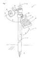
- the lamp 1 shows a solar powered lamp 1, in particular for outdoor use, shown with a post 3 in a floor 2, for example a lawn or a garden bed, is plugged.
- the lamp 1 also has a holder 11, in the direction of the sun aligned a variety of solar cells 4 attached are.
- the solar cells 4 together form a solar cell array 5.
- control electronics In the holder 11 are further not shown control electronics and provided at least one accumulator.
- the solar cells 4 convert the light energy into electrical energy and give it during the day, so during the Conversion process to the accumulator continues, the electrical energy stores.
- the light source 6 and the holder 11 are by means of a respective joint 12 in the attached movably to the upper part of the post 3.
- a respective joint 12 in the attached movably to the upper part of the post 3.
- the joint 12 has a further degree of freedom, so that the Inclination angle of both the light source 6 and the holder 11 relative to the vertical axis 9 of the post 3 can be pivoted.
- the holder 11 and the light source 6 in a ring 13 is pivotable held.
- the ring 13 is in each case via the joint 12 in the same way as that Exemplary embodiment Figure 1 connected to the post 3. It exists the Possibility to form the ring 13 as an outwardly open semicircle, so that this the light beams of the light source 6 as well as the incident on the solar panel 5 Sunbeams are not obstructed.
- the holder 11 ' is spherical and the post 3 has an im Cross-section V-shaped receiving pocket, in which the holder 11 'fixed is used. Between the V-shaped receiving pocket and the post 3 is the Joint 12 provided so that the inclination angle of the holder 11 'from the vertical Axis 9 can be adjusted inclined.
- the spherical holder 11 ' has in its interior an additional, not shown Light source, so that the holder 11 'can be illuminated.
- the holder 11 ' is made of a transparent or transparent material.
- Figure 4 it can be seen that in the circumferential direction of the holder 11 'a Nut 16 is formed on which a bracket 14 surrounds it at two positions. Consequently, the bracket 14 can be moved in the circumferential direction of the holder 11 '. At the same time it is possible, the bracket 14 at its middle position, the light source. 6 is attached, in any angular position about the two pivot points to the To tilt sliding blocks 16.
- the light source. 6 can be aligned independently of the positioning of the solar cell array 5. This significantly increases the efficiency of the solar-powered lamp 1, because the Solar cell array 5 can by adjusting the inclination ⁇ be moved so that the sun's rays more or less perpendicular to the Solar field incident and therefore given during the day a sufficiently large incidence of light is.
- the light source 6 is designed as a radiator, by means of which an exact Lighting a particular object made during the night can be.
- the purpose and the efficiency of the solar powered lamp 1 is therefore significantly improved.
- the holder 11 is formed as a leaf of a flower or a tree.
- the light source 6 may represent a stylized flower of a plant, so that the lamp 1 a causes natural aesthetic effect.
Landscapes
- Engineering & Computer Science (AREA)
- General Engineering & Computer Science (AREA)
- Life Sciences & Earth Sciences (AREA)
- Sustainable Development (AREA)
- Photovoltaic Devices (AREA)
- Non-Portable Lighting Devices Or Systems Thereof (AREA)
- Illuminated Signs And Luminous Advertising (AREA)
- Liquid Crystal Substances (AREA)
- Cultivation Of Plants (AREA)
Abstract
Description
- Figur 1
- ein erstes Ausführungsbeispiel der solarbetriebenen Leuchte mit einem die Solarzellen aufnehmenden Halter und einem Strahler,
- Figur 2
- ein zweites Ausführungsbeispiel einer solarbetriebenen Leuchte mit einem in einem Halter untergebrachten Solarzellenfeld und einer Lichtquelle, die jeweils in einem Ring verschwenkbar gehalten sind,
- Figur 3
- ein drittes Ausführungsbeispiel einer solarbetriebenen Leuchte mit einem kugelförmigen eine Vielzahl von Solarzellen aufnehmenden Halter, an dem ein Bügel, an dem die Lichtquelle befestigt ist, drehbar und neigbar gehalten ist, und
- Figur 4
- eine Vergrößerung des dritten Ausführungsbeispieles im Schnitt entlang der Schnittlinie IV - IV der Figur 3.
Claims (8)
- Solarbetriebene Leuchte (1), insbesondere für den Betrieb im Freien, mit einer Vielzahl von in einem Halter (11) eingesetzten Solarzellen (4), die ein Solarzellenfeld (5) bilden, und mit mindestens einer mit dem Solarzellenfeld (5) elektrisch verbundenen Lichtquelle (6),
dadurch gekennzeichnet, dass der Halter (11) des Solarzellenfeldes (5) und die Lichtquelle (6) als gesonderte Bauteile ausgebildet sind, die unabhängig voneinander ausrichtbar und/oder einstellbar sind. - Leuchte nach Anspruch 1,
dadurch gekennzeichnet, dass die Lichtquelle (6) und/ oder der das Solarzellenfeld (5), eine Steuerelektronik sowie einen oder mehreren Akkumulatoren aufnehmende Halter (11) an einem Pfosten (3), einem Stab oder dgl. angebracht sind und dass die Lichtquelle (6) und/oder der Halter (11) mittels eines Gelenkes (12) an dem Pfosten (3) abgestützt sind. - Leuchte nach Anspruch 2,
dadurch gekennzeichnet, dass das Gelenk (12) als Kardangelenk mit mindestens zwei Freiheitsgraden ausgebildet ist. - Leuchte nach Anspruch 2 oder 3,
dadurch gekennzeichnet, dass der Halter (11) und/oder die Lichtquelle (6) in einem Ring (13), der relativ zu dem Pfosten (3) drehbar ist, gehalten sind. - Leuchte nach einem oder mehreren der Ansprüche 1 bis 4,
dadurch gekennzeichnet, dass die Lichtquelle (6) in einem Bügel (14) angeordnet ist und dass der Bügel (14) drehbar und/oder neigbar an dem Halter (11) abgestützt ist. - Leuchte nach einem oder mehreren der vorgenannten Ansprüche,
dadurch gekennzeichnet, dass der Halter (11) als Blatt einer Blume, eines Baumes oder dgl. gestaltet ist. - Leuchte nach einem oder mehreren der vorgenannten Ansprüche,
dadurch gekennzeichnet, dass die Lichtquelle (6) als Strahler ausgebildet ist. - Leuchte nach einem oder mehreren der vorgenannten Ansprüche,
dadurch gekennzeichnet, dass mehrere Solarzellenfelder (5) vorgesehen sind, die in voneinander getrennten Halter (11) befestigt sind.
Applications Claiming Priority (2)
| Application Number | Priority Date | Filing Date | Title |
|---|---|---|---|
| DE20311585U | 2003-07-25 | ||
| DE20311585U DE20311585U1 (de) | 2003-07-25 | 2003-07-25 | Solarbetriebene Leuchte |
Publications (2)
| Publication Number | Publication Date |
|---|---|
| EP1500870A1 true EP1500870A1 (de) | 2005-01-26 |
| EP1500870B1 EP1500870B1 (de) | 2006-08-30 |
Family
ID=29225427
Family Applications (1)
| Application Number | Title | Priority Date | Filing Date |
|---|---|---|---|
| EP04012171A Expired - Lifetime EP1500870B1 (de) | 2003-07-25 | 2004-05-22 | Solarbetriebene Leuchte |
Country Status (3)
| Country | Link |
|---|---|
| EP (1) | EP1500870B1 (de) |
| AT (1) | ATE338245T1 (de) |
| DE (2) | DE20311585U1 (de) |
Cited By (10)
| Publication number | Priority date | Publication date | Assignee | Title |
|---|---|---|---|---|
| WO2010122179A1 (es) * | 2009-04-20 | 2010-10-28 | Siarq, S.L. | Sistema de alumbrado de alimentación fotovoltáica e intensidad lumínica programable y regulable in situ o bien a distancia |
| US7891832B2 (en) | 2005-05-18 | 2011-02-22 | Allsop, Inc. | Outdoor light with positionable solar collector |
| EP2638319A4 (de) * | 2010-11-13 | 2014-12-17 | Stephen Katsaros | Einstellbare durch solarenergie aufgeladene lampe |
| WO2016119203A1 (zh) * | 2015-01-30 | 2016-08-04 | 凯灿贸易(深圳)有限公司 | 一种太阳能激光灯 |
| GR20160100153A (el) * | 2016-04-12 | 2017-11-30 | Ειρηνη Ευαγγελου Παπαδακη | Αυτονομο φωτιστικο με ηλιακο συλλεκτη |
| US9839088B1 (en) | 2016-03-10 | 2017-12-05 | Heathco, Llc | Security light with remote photo-voltaic module and battery backup and related methods |
| EP3255335A4 (de) * | 2015-02-05 | 2018-01-03 | Alessandro Caviasca | Fotovoltaisches modul |
| CN110864260A (zh) * | 2019-12-04 | 2020-03-06 | 深圳市若盛科技有限公司 | 一种高实用性太阳能灯 |
| US10718500B1 (en) | 2019-08-30 | 2020-07-21 | HealthCo LLC | Solar powered security light with variable mounting |
| US20230358377A1 (en) * | 2022-03-31 | 2023-11-09 | Alliance Sports Group | Outdoor Lighting Apparatus |
Families Citing this family (11)
| Publication number | Priority date | Publication date | Assignee | Title |
|---|---|---|---|---|
| WO2005114043A1 (en) * | 2004-05-14 | 2005-12-01 | Allsop, Inc. | Offset solar-powered outdoor lighting apparatus |
| ITPD20040198A1 (it) * | 2004-07-23 | 2004-10-23 | Lino Manfrotto & Co Spa | Supporto per apparecchiiature elettroniche, particolarmente di tipo video fotografico |
| GB0512984D0 (en) * | 2005-06-27 | 2005-08-03 | Bu Innovations Ltd | Pickable solar powered light |
| DE102007013129A1 (de) * | 2007-03-15 | 2008-09-25 | Stadtfeld Elektrotechnische Fabrik Gmbh & Co. Kg | Beleuchtungsvorrichtung, insbesondere netzunabhängige Beleuchtungsvorrichtung, und Beleuchtungsverbund |
| DE102007045119A1 (de) * | 2007-09-20 | 2009-04-02 | Trilux Gmbh & Co. Kg | Variabel einsetzbare Außenleuchte |
| DE202012100891U1 (de) * | 2012-03-13 | 2013-06-14 | Steinel Gmbh | Leuchtenvorrichtung |
| BE1024073B1 (nl) * | 2015-12-23 | 2017-11-10 | Rik Hiergens | Verlichting voor toepassing in een tuin of in een plantrijke omgeving of dergelijke. |
| CN106678612A (zh) * | 2016-11-10 | 2017-05-17 | 成都朵猫文化传播有限公司 | 一种园林灯 |
| DE202018000444U1 (de) | 2018-01-18 | 2018-02-22 | Ronotic Ag | Solarleuchte |
| DE102018000677A1 (de) | 2018-01-18 | 2019-07-18 | Ronotic Ag | Solarleuchte |
| US11950677B2 (en) | 2019-02-28 | 2024-04-09 | L'oreal | Devices and methods for electrostatic application of cosmetics |
Citations (8)
| Publication number | Priority date | Publication date | Assignee | Title |
|---|---|---|---|---|
| US4486820A (en) * | 1980-07-16 | 1984-12-04 | Kyoto Ceramic Company Limited | Lighting equipment with a solar cell |
| US4977488A (en) * | 1990-03-14 | 1990-12-11 | Australux North America Ltd. | Solar powered outdoor recreational light with positionable solar panel |
| DE29521271U1 (de) * | 1995-05-03 | 1996-11-21 | Kämpf, Hartmut, 98529 Suhl | Autarke Beleuchtungseinrichtung für flächenhafte Werbeträger |
| DE29920735U1 (de) * | 1999-11-26 | 2000-05-25 | Trisl, Klaus, 65197 Wiesbaden | KT-Solarflächen-Träger mit kardanischer Aufhängung |
| US6107941A (en) * | 1991-10-09 | 2000-08-22 | R. D. Jones, Right Of Way, Inc. | Traffic control system and kit |
| DE10026524A1 (de) | 2000-05-27 | 2001-12-06 | Solar Trend Gmbh | Solarleuchte |
| EP1178261A2 (de) * | 2000-07-31 | 2002-02-06 | Rudolf Zimmermann GmbH & Co. KG. | Solarleuchte mit einem im wesentlichen kugelförmigen, mindestens teilweise lichtdurchlässigen Leuchtenkörper |
| DE10201816A1 (de) | 2002-01-18 | 2003-07-31 | Wagner Gmbh J | Vorrichtung zur Umwandlung von Sonnenenergie |
-
2003
- 2003-07-25 DE DE20311585U patent/DE20311585U1/de not_active Expired - Lifetime
-
2004
- 2004-05-22 AT AT04012171T patent/ATE338245T1/de not_active IP Right Cessation
- 2004-05-22 DE DE502004001313T patent/DE502004001313D1/de not_active Expired - Fee Related
- 2004-05-22 EP EP04012171A patent/EP1500870B1/de not_active Expired - Lifetime
Patent Citations (8)
| Publication number | Priority date | Publication date | Assignee | Title |
|---|---|---|---|---|
| US4486820A (en) * | 1980-07-16 | 1984-12-04 | Kyoto Ceramic Company Limited | Lighting equipment with a solar cell |
| US4977488A (en) * | 1990-03-14 | 1990-12-11 | Australux North America Ltd. | Solar powered outdoor recreational light with positionable solar panel |
| US6107941A (en) * | 1991-10-09 | 2000-08-22 | R. D. Jones, Right Of Way, Inc. | Traffic control system and kit |
| DE29521271U1 (de) * | 1995-05-03 | 1996-11-21 | Kämpf, Hartmut, 98529 Suhl | Autarke Beleuchtungseinrichtung für flächenhafte Werbeträger |
| DE29920735U1 (de) * | 1999-11-26 | 2000-05-25 | Trisl, Klaus, 65197 Wiesbaden | KT-Solarflächen-Träger mit kardanischer Aufhängung |
| DE10026524A1 (de) | 2000-05-27 | 2001-12-06 | Solar Trend Gmbh | Solarleuchte |
| EP1178261A2 (de) * | 2000-07-31 | 2002-02-06 | Rudolf Zimmermann GmbH & Co. KG. | Solarleuchte mit einem im wesentlichen kugelförmigen, mindestens teilweise lichtdurchlässigen Leuchtenkörper |
| DE10201816A1 (de) | 2002-01-18 | 2003-07-31 | Wagner Gmbh J | Vorrichtung zur Umwandlung von Sonnenenergie |
Cited By (16)
| Publication number | Priority date | Publication date | Assignee | Title |
|---|---|---|---|---|
| US7891832B2 (en) | 2005-05-18 | 2011-02-22 | Allsop, Inc. | Outdoor light with positionable solar collector |
| WO2010122179A1 (es) * | 2009-04-20 | 2010-10-28 | Siarq, S.L. | Sistema de alumbrado de alimentación fotovoltáica e intensidad lumínica programable y regulable in situ o bien a distancia |
| EP2638319A4 (de) * | 2010-11-13 | 2014-12-17 | Stephen Katsaros | Einstellbare durch solarenergie aufgeladene lampe |
| US9200767B2 (en) | 2010-11-13 | 2015-12-01 | Stephen Katsaros | Adjustable solar charged lamp |
| US9429281B2 (en) | 2010-11-13 | 2016-08-30 | Stephen Katsaros | Adjustable solar charged lamp |
| AP3786A (en) * | 2010-11-13 | 2016-08-31 | Stephen Katsaros | Adjustable solar charged lamp |
| US10234083B2 (en) | 2010-11-13 | 2019-03-19 | Stephen Katsaros | Adjustable solar charged lamp |
| WO2016119203A1 (zh) * | 2015-01-30 | 2016-08-04 | 凯灿贸易(深圳)有限公司 | 一种太阳能激光灯 |
| EP3255335A4 (de) * | 2015-02-05 | 2018-01-03 | Alessandro Caviasca | Fotovoltaisches modul |
| US9839088B1 (en) | 2016-03-10 | 2017-12-05 | Heathco, Llc | Security light with remote photo-voltaic module and battery backup and related methods |
| GR20160100153A (el) * | 2016-04-12 | 2017-11-30 | Ειρηνη Ευαγγελου Παπαδακη | Αυτονομο φωτιστικο με ηλιακο συλλεκτη |
| US10718500B1 (en) | 2019-08-30 | 2020-07-21 | HealthCo LLC | Solar powered security light with variable mounting |
| US11073267B1 (en) | 2019-08-30 | 2021-07-27 | Heathco Llc | Solar powered security light with variable mounting |
| CN110864260A (zh) * | 2019-12-04 | 2020-03-06 | 深圳市若盛科技有限公司 | 一种高实用性太阳能灯 |
| US20230358377A1 (en) * | 2022-03-31 | 2023-11-09 | Alliance Sports Group | Outdoor Lighting Apparatus |
| US11906133B2 (en) * | 2022-03-31 | 2024-02-20 | Alliance Sports Group, L.P. | Outdoor lighting apparatus |
Also Published As
| Publication number | Publication date |
|---|---|
| EP1500870B1 (de) | 2006-08-30 |
| DE502004001313D1 (de) | 2006-10-12 |
| ATE338245T1 (de) | 2006-09-15 |
| DE20311585U1 (de) | 2003-10-09 |
Similar Documents
| Publication | Publication Date | Title |
|---|---|---|
| EP1500870B1 (de) | Solarbetriebene Leuchte | |
| EP1514060A1 (de) | Selbsttätig wirkende sonnenstandsnachführeinrichtung | |
| EP2166277A1 (de) | Beleuchtungsvorrichtung | |
| DE102005033777A1 (de) | Überdachung mit Beleuchtungseinrichtung | |
| DE102004013590B4 (de) | Solarkonzentrator mit mehreren Spiegeln | |
| DE102006022982B4 (de) | Vorrichtung zur Montierung wenigstens eines Solarmoduls zur wenigstens einachsigen Nachführung | |
| DE202006015917U1 (de) | Solaranlage | |
| EP1852649A1 (de) | Solarbetriebene Mastleuchte | |
| DE102018002190A1 (de) | Leuchtenmast | |
| DE102006010781A1 (de) | Sonnenstandsnachführeinrichtung für ein Solarmodul | |
| DE10037237C2 (de) | Solarleuchte mit einem im wesentlichen kugelförmigen, mindestens teilweise lichtdurchlässigen Leuchtenkörper | |
| DE8803720U1 (de) | Leuchte, insbesondere Straßenleuchte | |
| DE4210522A1 (de) | Außenleuchte mit Blumen- und Pflanzenträger | |
| DE4020032C2 (de) | Vorrichtung zur Umwandlung von Sonnenenergie in Strom, insbesondere zum Nachladen der Batterien elektrisch angetriebener Fahrzeuge | |
| DE10129478C2 (de) | Solarmodul-/Verbraucheraggregat | |
| EP2639502B1 (de) | Leuchtenvorrichtung | |
| DE19928857C2 (de) | Zweiachsig nachführbare Solarzellenanordnung | |
| DE102018006506B4 (de) | Leuchte für Arbeits-, Film- oder Sportveranstaltungen | |
| DE102009022876A1 (de) | Nachführeinheit sowie Sonnenkollektor- oder Photovoltaikeinheit | |
| DE202012000843U1 (de) | Solareinrichtung mit Reflektorvorrichtung und Reflektorvorrichtung | |
| DE10045028A1 (de) | Beleuchtungsanlage zur Simulation des Sonnenlichts | |
| CH683454A5 (de) | Leuchterobjekt. | |
| DE102018000677A1 (de) | Solarleuchte | |
| DE10026524A1 (de) | Solarleuchte | |
| DE202018000444U1 (de) | Solarleuchte |
Legal Events
| Date | Code | Title | Description |
|---|---|---|---|
| PUAI | Public reference made under article 153(3) epc to a published international application that has entered the european phase |
Free format text: ORIGINAL CODE: 0009012 |
|
| AK | Designated contracting states |
Kind code of ref document: A1 Designated state(s): AT BE BG CH CY CZ DE DK EE ES FI FR GB GR HU IE IT LI LU MC NL PL PT RO SE SI SK TR |
|
| AX | Request for extension of the european patent |
Extension state: AL HR LT LV MK |
|
| 17P | Request for examination filed |
Effective date: 20050709 |
|
| AKX | Designation fees paid |
Designated state(s): AT BE BG CH CY CZ DE DK EE ES FI FR GB GR HU IE IT LI LU MC NL PL PT RO SE SI SK TR |
|
| GRAP | Despatch of communication of intention to grant a patent |
Free format text: ORIGINAL CODE: EPIDOSNIGR1 |
|
| GRAS | Grant fee paid |
Free format text: ORIGINAL CODE: EPIDOSNIGR3 |
|
| GRAA | (expected) grant |
Free format text: ORIGINAL CODE: 0009210 |
|
| AK | Designated contracting states |
Kind code of ref document: B1 Designated state(s): AT BE BG CH CY CZ DE DK EE ES FI FR GB GR HU IE IT LI LU MC NL PL PT RO SE SI SK TR |
|
| PG25 | Lapsed in a contracting state [announced via postgrant information from national office to epo] |
Ref country code: IT Free format text: LAPSE BECAUSE OF FAILURE TO SUBMIT A TRANSLATION OF THE DESCRIPTION OR TO PAY THE FEE WITHIN THE PRESCRIBED TIME-LIMIT;WARNING: LAPSES OF ITALIAN PATENTS WITH EFFECTIVE DATE BEFORE 2007 MAY HAVE OCCURRED AT ANY TIME BEFORE 2007. THE CORRECT EFFECTIVE DATE MAY BE DIFFERENT FROM THE ONE RECORDED. Effective date: 20060830 Ref country code: NL Free format text: LAPSE BECAUSE OF FAILURE TO SUBMIT A TRANSLATION OF THE DESCRIPTION OR TO PAY THE FEE WITHIN THE PRESCRIBED TIME-LIMIT Effective date: 20060830 Ref country code: IE Free format text: LAPSE BECAUSE OF FAILURE TO SUBMIT A TRANSLATION OF THE DESCRIPTION OR TO PAY THE FEE WITHIN THE PRESCRIBED TIME-LIMIT Effective date: 20060830 Ref country code: PL Free format text: LAPSE BECAUSE OF FAILURE TO SUBMIT A TRANSLATION OF THE DESCRIPTION OR TO PAY THE FEE WITHIN THE PRESCRIBED TIME-LIMIT Effective date: 20060830 Ref country code: RO Free format text: LAPSE BECAUSE OF FAILURE TO SUBMIT A TRANSLATION OF THE DESCRIPTION OR TO PAY THE FEE WITHIN THE PRESCRIBED TIME-LIMIT Effective date: 20060830 Ref country code: SK Free format text: LAPSE BECAUSE OF FAILURE TO SUBMIT A TRANSLATION OF THE DESCRIPTION OR TO PAY THE FEE WITHIN THE PRESCRIBED TIME-LIMIT Effective date: 20060830 Ref country code: SI Free format text: LAPSE BECAUSE OF FAILURE TO SUBMIT A TRANSLATION OF THE DESCRIPTION OR TO PAY THE FEE WITHIN THE PRESCRIBED TIME-LIMIT Effective date: 20060830 Ref country code: FI Free format text: LAPSE BECAUSE OF FAILURE TO SUBMIT A TRANSLATION OF THE DESCRIPTION OR TO PAY THE FEE WITHIN THE PRESCRIBED TIME-LIMIT Effective date: 20060830 Ref country code: CZ Free format text: LAPSE BECAUSE OF FAILURE TO SUBMIT A TRANSLATION OF THE DESCRIPTION OR TO PAY THE FEE WITHIN THE PRESCRIBED TIME-LIMIT Effective date: 20060830 Ref country code: GB Free format text: LAPSE BECAUSE OF FAILURE TO SUBMIT A TRANSLATION OF THE DESCRIPTION OR TO PAY THE FEE WITHIN THE PRESCRIBED TIME-LIMIT Effective date: 20060830 |
|
| REG | Reference to a national code |
Ref country code: GB Ref legal event code: FG4D Free format text: NOT ENGLISH |
|
| REG | Reference to a national code |
Ref country code: CH Ref legal event code: EP |
|
| REG | Reference to a national code |
Ref country code: IE Ref legal event code: FG4D Free format text: LANGUAGE OF EP DOCUMENT: GERMAN |
|
| REF | Corresponds to: |
Ref document number: 502004001313 Country of ref document: DE Date of ref document: 20061012 Kind code of ref document: P |
|
| PG25 | Lapsed in a contracting state [announced via postgrant information from national office to epo] |
Ref country code: SE Free format text: LAPSE BECAUSE OF FAILURE TO SUBMIT A TRANSLATION OF THE DESCRIPTION OR TO PAY THE FEE WITHIN THE PRESCRIBED TIME-LIMIT Effective date: 20061130 Ref country code: DK Free format text: LAPSE BECAUSE OF FAILURE TO SUBMIT A TRANSLATION OF THE DESCRIPTION OR TO PAY THE FEE WITHIN THE PRESCRIBED TIME-LIMIT Effective date: 20061130 Ref country code: BG Free format text: LAPSE BECAUSE OF FAILURE TO SUBMIT A TRANSLATION OF THE DESCRIPTION OR TO PAY THE FEE WITHIN THE PRESCRIBED TIME-LIMIT Effective date: 20061130 |
|
| PG25 | Lapsed in a contracting state [announced via postgrant information from national office to epo] |
Ref country code: ES Free format text: LAPSE BECAUSE OF FAILURE TO SUBMIT A TRANSLATION OF THE DESCRIPTION OR TO PAY THE FEE WITHIN THE PRESCRIBED TIME-LIMIT Effective date: 20061211 |
|
| PG25 | Lapsed in a contracting state [announced via postgrant information from national office to epo] |
Ref country code: PT Free format text: LAPSE BECAUSE OF FAILURE TO SUBMIT A TRANSLATION OF THE DESCRIPTION OR TO PAY THE FEE WITHIN THE PRESCRIBED TIME-LIMIT Effective date: 20070206 |
|
| NLV1 | Nl: lapsed or annulled due to failure to fulfill the requirements of art. 29p and 29m of the patents act | ||
| GBV | Gb: ep patent (uk) treated as always having been void in accordance with gb section 77(7)/1977 [no translation filed] |
Effective date: 20060830 |
|
| REG | Reference to a national code |
Ref country code: IE Ref legal event code: FD4D |
|
| EN | Fr: translation not filed | ||
| PLBE | No opposition filed within time limit |
Free format text: ORIGINAL CODE: 0009261 |
|
| STAA | Information on the status of an ep patent application or granted ep patent |
Free format text: STATUS: NO OPPOSITION FILED WITHIN TIME LIMIT |
|
| 26N | No opposition filed |
Effective date: 20070531 |
|
| BERE | Be: lapsed |
Owner name: J. WAGNER G.M.B.H. Effective date: 20070531 |
|
| PG25 | Lapsed in a contracting state [announced via postgrant information from national office to epo] |
Ref country code: MC Free format text: LAPSE BECAUSE OF NON-PAYMENT OF DUE FEES Effective date: 20070531 |
|
| PG25 | Lapsed in a contracting state [announced via postgrant information from national office to epo] |
Ref country code: BE Free format text: LAPSE BECAUSE OF NON-PAYMENT OF DUE FEES Effective date: 20070531 |
|
| PG25 | Lapsed in a contracting state [announced via postgrant information from national office to epo] |
Ref country code: GR Free format text: LAPSE BECAUSE OF FAILURE TO SUBMIT A TRANSLATION OF THE DESCRIPTION OR TO PAY THE FEE WITHIN THE PRESCRIBED TIME-LIMIT Effective date: 20061201 Ref country code: FR Free format text: LAPSE BECAUSE OF FAILURE TO SUBMIT A TRANSLATION OF THE DESCRIPTION OR TO PAY THE FEE WITHIN THE PRESCRIBED TIME-LIMIT Effective date: 20070511 |
|
| PG25 | Lapsed in a contracting state [announced via postgrant information from national office to epo] |
Ref country code: EE Free format text: LAPSE BECAUSE OF FAILURE TO SUBMIT A TRANSLATION OF THE DESCRIPTION OR TO PAY THE FEE WITHIN THE PRESCRIBED TIME-LIMIT Effective date: 20060830 |
|
| PGFP | Annual fee paid to national office [announced via postgrant information from national office to epo] |
Ref country code: AT Payment date: 20080521 Year of fee payment: 5 |
|
| PG25 | Lapsed in a contracting state [announced via postgrant information from national office to epo] |
Ref country code: FR Free format text: LAPSE BECAUSE OF FAILURE TO SUBMIT A TRANSLATION OF THE DESCRIPTION OR TO PAY THE FEE WITHIN THE PRESCRIBED TIME-LIMIT Effective date: 20060830 |
|
| PG25 | Lapsed in a contracting state [announced via postgrant information from national office to epo] |
Ref country code: LU Free format text: LAPSE BECAUSE OF NON-PAYMENT OF DUE FEES Effective date: 20070522 Ref country code: CY Free format text: LAPSE BECAUSE OF FAILURE TO SUBMIT A TRANSLATION OF THE DESCRIPTION OR TO PAY THE FEE WITHIN THE PRESCRIBED TIME-LIMIT Effective date: 20060830 |
|
| PG25 | Lapsed in a contracting state [announced via postgrant information from national office to epo] |
Ref country code: TR Free format text: LAPSE BECAUSE OF FAILURE TO SUBMIT A TRANSLATION OF THE DESCRIPTION OR TO PAY THE FEE WITHIN THE PRESCRIBED TIME-LIMIT Effective date: 20060830 Ref country code: HU Free format text: LAPSE BECAUSE OF FAILURE TO SUBMIT A TRANSLATION OF THE DESCRIPTION OR TO PAY THE FEE WITHIN THE PRESCRIBED TIME-LIMIT Effective date: 20070301 |
|
| PGFP | Annual fee paid to national office [announced via postgrant information from national office to epo] |
Ref country code: CH Payment date: 20090515 Year of fee payment: 6 |
|
| PGFP | Annual fee paid to national office [announced via postgrant information from national office to epo] |
Ref country code: DE Payment date: 20090625 Year of fee payment: 6 |
|
| PG25 | Lapsed in a contracting state [announced via postgrant information from national office to epo] |
Ref country code: AT Free format text: LAPSE BECAUSE OF NON-PAYMENT OF DUE FEES Effective date: 20090522 |
|
| REG | Reference to a national code |
Ref country code: CH Ref legal event code: PL |
|
| PG25 | Lapsed in a contracting state [announced via postgrant information from national office to epo] |
Ref country code: CH Free format text: LAPSE BECAUSE OF NON-PAYMENT OF DUE FEES Effective date: 20100531 Ref country code: LI Free format text: LAPSE BECAUSE OF NON-PAYMENT OF DUE FEES Effective date: 20100531 |
|
| PG25 | Lapsed in a contracting state [announced via postgrant information from national office to epo] |
Ref country code: DE Free format text: LAPSE BECAUSE OF NON-PAYMENT OF DUE FEES Effective date: 20101201 |