EP1500529B1 - Suspension d'essieu rigide pour vehicules - Google Patents
Suspension d'essieu rigide pour vehicules Download PDFInfo
- Publication number
- EP1500529B1 EP1500529B1 EP04015013A EP04015013A EP1500529B1 EP 1500529 B1 EP1500529 B1 EP 1500529B1 EP 04015013 A EP04015013 A EP 04015013A EP 04015013 A EP04015013 A EP 04015013A EP 1500529 B1 EP1500529 B1 EP 1500529B1
- Authority
- EP
- European Patent Office
- Prior art keywords
- console
- buffer
- recess
- axle
- diameter
- Prior art date
- Legal status (The legal status is an assumption and is not a legal conclusion. Google has not performed a legal analysis and makes no representation as to the accuracy of the status listed.)
- Expired - Lifetime
Links
Images

Classifications
-
- B—PERFORMING OPERATIONS; TRANSPORTING
- B60—VEHICLES IN GENERAL
- B60G—VEHICLE SUSPENSION ARRANGEMENTS
- B60G11/00—Resilient suspensions characterised by arrangement, location or kind of springs
- B60G11/02—Resilient suspensions characterised by arrangement, location or kind of springs having leaf springs only
- B60G11/10—Resilient suspensions characterised by arrangement, location or kind of springs having leaf springs only characterised by means specially adapted for attaching the spring to axle or sprung part of the vehicle
-
- B—PERFORMING OPERATIONS; TRANSPORTING
- B60—VEHICLES IN GENERAL
- B60G—VEHICLE SUSPENSION ARRANGEMENTS
- B60G11/00—Resilient suspensions characterised by arrangement, location or kind of springs
- B60G11/32—Resilient suspensions characterised by arrangement, location or kind of springs having springs of different kinds
- B60G11/34—Resilient suspensions characterised by arrangement, location or kind of springs having springs of different kinds including leaf springs
- B60G11/38—Resilient suspensions characterised by arrangement, location or kind of springs having springs of different kinds including leaf springs and also rubber springs
- B60G11/40—Resilient suspensions characterised by arrangement, location or kind of springs having springs of different kinds including leaf springs and also rubber springs the rubber springs being attached to the axle
-
- B—PERFORMING OPERATIONS; TRANSPORTING
- B60—VEHICLES IN GENERAL
- B60G—VEHICLE SUSPENSION ARRANGEMENTS
- B60G7/00—Pivoted suspension arms; Accessories thereof
- B60G7/04—Buffer means for limiting movement of arms
-
- B—PERFORMING OPERATIONS; TRANSPORTING
- B60—VEHICLES IN GENERAL
- B60G—VEHICLE SUSPENSION ARRANGEMENTS
- B60G9/00—Resilient suspensions of a rigid axle or axle housing for two or more wheels
- B60G9/003—Resilient suspensions of a rigid axle or axle housing for two or more wheels the axle being rigidly connected to a trailing guiding device
-
- B—PERFORMING OPERATIONS; TRANSPORTING
- B60—VEHICLES IN GENERAL
- B60G—VEHICLE SUSPENSION ARRANGEMENTS
- B60G2202/00—Indexing codes relating to the type of spring, damper or actuator
- B60G2202/10—Type of spring
- B60G2202/11—Leaf spring
- B60G2202/112—Leaf spring longitudinally arranged
-
- B—PERFORMING OPERATIONS; TRANSPORTING
- B60—VEHICLES IN GENERAL
- B60G—VEHICLE SUSPENSION ARRANGEMENTS
- B60G2204/00—Indexing codes related to suspensions per se or to auxiliary parts
- B60G2204/40—Auxiliary suspension parts; Adjustment of suspensions
- B60G2204/45—Stops limiting travel
- B60G2204/4502—Stops limiting travel using resilient buffer
Definitions
- the invention relates to a sprung suspension of a rigid axle in a motor vehicle with features, as indicated in the preamble of claim 1.
- a sprung axle suspension of the generic type is on the one hand from the JP 55-099405 known.
- it has been used in Bentley vehicles of the years of construction until 1934, which is evident in the corresponding vintage cars.
- As a bump stop is a square, about two centimeters thick disk of limited elastic material for use, which is probably vulcanized or glued into the recess of the console. The actual connection is not detectable on said vintage cars.
- the stop buffer can be attached quickly and in the simplest form to the console.
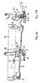
- FIG. 1 of a vehicle a portion of a part of the chassis forming frame side member 1 is shown, on which a rigid axle is sprung with its axle body 2 and fixed, by means of a leaf spring 3, consisting of a single Spring leaf or a leaf spring package may exist.
- the leaf spring 3 is fixed one end with its spring eye 4 to a frame-fixed bracket 5 and articulated with its other end given spring eye 6 on a rocker 7 and flying over this on a frame-fixed bearing block 8.
- 9 is a shock absorber and 10 denotes a stabilizer, both of which are articulated on the one hand on the axle body 2 and on the other hand on the frame longitudinal member 1.
- the axle body 2 of the rigid axle is attached to the underside of the leaf spring 3 by means of two U-shaped retaining bracket 11, 12. These overlap a console 13 resting on top of the leaf spring 3 and tighten them there by means of nuts 14 resting on the axle body 2 at the bottom.
- the console 13 has a recess 15 at the top, in which a stop buffer 16 is accommodated, which limits the jounce path when the frame is spring-loaded with respect to the rigid axle in cooperation with a frame-fixed stop 17.
- a stop buffer 16 is accommodated, which limits the jounce path when the frame is spring-loaded with respect to the rigid axle in cooperation with a frame-fixed stop 17.
- the console 13 on either side of its recess 15 depending on a transverse channel 18, 19 given, in each of which one of the two brackets 11, 12 is fixed in position added.
- this stop buffer 16 is used as a stop buffer 16, one having a buffer body 20 and at the bottom of this a mushroom-shaped mounting pin 21, the neck 22 and head 23 are designated.
- this stop buffer 16 is added according to the invention dipped with a lower portion 24 of its buffer body 20 in the correspondingly formed upper recess 15 of the console 13.
- this stop buffer 16 penetrates according to the invention with the neck 22 of its mushroom-shaped fastening pin 21 through-hole 25 in the console 13 and immersed with the head 23 of its mounting pin 21 in a given below in the console 13 recess 26 and is there at the bottom 27, the edge around the through hole 25 engages behind, locked.
- the stop buffer 16 has, at least in that lower region 24, with which it dips into the upper recess 15 of the bracket 15, a circular cylindrical cross-section, to which the mushroom-shaped fastening pin 21 is arranged coaxially.
- the through hole 25 in the bracket 13 is upwardly to the bottom 29 of the upper recess 15 towards conically chamfered or strongly rounded, which favors a proper and damage-free insertion of the mushroom-shaped fixing pin 21 on the stop buffer 16 during its mounting on the console 13.
- the neck 22 of the mushroom-shaped fastening pin 21 on the stop buffer 16 has a slight, z. B. a few tenths of a millimeter, smaller diameter than the through hole 25 in the console 13 and a length corresponding to the distance of the bottoms 27, 29 of the two recesses 15, 16 in the console 23 and the thickness of the wall 30 given therebetween or is a few tenths of a millimeter larger than this one.
- the stop buffer 16 is made of limited elastic material, for. B. hard rubber or a suitable plastic.
- the head 23 of the mushroom-shaped fastening pin 21 has a diameter which is larger in relation to that of the neck 22 so that it can initially be compressed to its diameter due to the flexibility of the stop buffer material when the stop buffer 16 is mounted on the bracket 13 when the through-bore 25 penetrates it then, after complete penetration of the through hole 25, can expand back to its given in locking position normal diameter.
- the head 23 of the mushroom-shaped fixing pin 21 tapers from its upper largest diameter at 31 conically with either straight or concave curved outer surface 32 to a smaller diameter at its end face 33, which is smaller by some extent than the diameter of the through hole 25 in FIG the console 13 is.
- the console 13 may - as shown - be formed in cross section approximately hat-shaped, wherein in its elevated central region 34, the upper recess 15 open at the top and the lower Recess 26 are formed open at the bottom. On both sides of this raised middle region 34, side regions 35, 36 of a base plate 37 adjoin, in the upper side of which the transverse channels 18, 19 are designed for receiving the retaining clips 11, 12.
- the upper recess 15 in the illustrated example is slightly larger in diameter than the immersed in it lower portion 24 of the stop buffer and also slightly larger than the width of the raised central region 34, so that the recess 15 is not completely closed.
- stop buffer 16 The connection of stop buffer 16 and console 13 can be done manually or robotically controlled.
- the stop buffer 16 is brought from above to the console 13 and then pressed further in the axial direction of the mushroom-like mounting pin 21 with its head 23 through the through hole 25.
- the previously compressed in the through hole 25 head 23 relaxes again on its given at 31 normal diameter, so that a certain edge area around the through hole 25 is engaged behind the bottom 27 of the lower recess 26 in the console by the head 23 and thereby the stop buffer 16 is fixedly mounted on the bracket 13.
Landscapes
- Engineering & Computer Science (AREA)
- Mechanical Engineering (AREA)
- Vehicle Body Suspensions (AREA)
- Vibration Dampers (AREA)
- Springs (AREA)
- Vibration Prevention Devices (AREA)
Claims (8)
- Suspension amortie d'un essieu rigide, en particulier d'un camion ou d'un bus, auquel cas le corps d'essieu (2) de l'essieu rigide est fixé en dessous sur un ressort à lame (3) suspendu à l'avant et à l'arrière sur le cadre du véhicule (1) et plus exactement par le biais de deux étriers de fixation en forme de U (11, 12) qui chevauchent une console (13) s'appuyant sur le dessous sur le ressort à lame (3) et bloquent celle-ci à cet endroit à l'aide d'écrous bloqués par contre-écrous en dessous sur le corps d'essieu (2), auquel cas la console (13) présente sur le dessus un évidement (15) dans lequel est logé un tampon de butée en appui pour le débattement sur le cadre ou sur une butée (17) fixée sur le cadre, ainsi que, de chaque côté de l'évidement (15), une rainure transversale (18, 19) dans laquelle est enfoncé à chaque fois un étrier de fixation (11, 12) de manière fixe, caractérisée en ce qu'est utilisé un tampon de butée (16) présentant en dessous un pivot de fixation en forme de champignon (21) sur un corps de tampon (20), en ce que ce tampon de butée (16) est logé par enfoncement dans l'évidement supérieur (15) de la console (13) avec une partie inférieure (24) de son corps de tampon (20), en outre traverse un alésage de passage (25) réalisé dans la console (13) avec la gorge (22) de son pivot de fixation en forme de champignon (21) et en plus est enfoncé dans un évidement (26) réalisé en dessous dans la console (13) avec la tête (23) de son pivot de fixation en forme de champignon (21) et est encranté sur le fond du même évidement, en prise par derrière avec la bordure autour de l'alésage de passage (25).
- Suspension d'essieu selon la revendication 1, caractérisée en ce que la face inférieure (28) du corps de tampon (20) sur le tampon de butée (16) est légèrement en forme de cône ou convexe et la base (29) de l'évidement supérieur (15) réalisé dans la console est adaptée en conséquence pour un montage par adhérence de cette face inférieure (28) du corps de tampon réalisé ainsi.
- Suspension d'essieu selon la revendication 1 ou 2, caractérisée en ce que l'alésage de passage (25) réalisé dans la console (13) est chanfreiné en forme de cône ou fortement arrondi sur le dessus au niveau du passage vers la base (29) de l'évidement supérieur (15).
- Suspension d'essieu selon l'une des revendications mentionnées précédemment, caractérisée en ce que la gorge (22) du pivot de fixation (21) présente un diamètre légèrement plus petit, par exemple de quelques dixièmes de millimètres, que l'alésage de passage (25) réalisé dans la console (13) au niveau du tampon de butée (16) et une longueur qui correspond à l'écart des bases (27, 29) des deux évidements (15, 26) ou de l'épaisseur de la paroi existante entre les deux, ou est supérieur de quelques dixièmes de millimètres par rapport à celle-ci.
- Suspension d'essieu selon l'une des revendications mentionnées précédemment, caractérisée en ce que la tête (23) du pivot de fixation en forme de champignon (21) sur le tampon de butée (16) présente un diamètre plus important que celui de la gorge (22) de telle manière qu'en raison de la souplesse du matériau du tampon de butée, elle puisse être enfoncée sur le diamètre de l'alésage de passage lors du montage du tampon de butée (16) sur la console (13) lors de la pénétration dans l'alésage de passage (25) et puisse s'étendre de nouveau sur son diamètre normal en position de blocage après une pénétration complète dans l'alésage de passage (25).
- Suspension d'essieu selon l'une des revendications mentionnées précédemment, caractérisée en ce que la tête (23) du pivot de fixation en forme de champignon (21) sur le tampon de butée (16) se rétrécit à partir de son diamètre supérieur plus important (31) sous forme de cône avec une surface extérieure (32) droite ou concave par rapport à un diamètre plus petit sur sa surface avant (33), lequel est de nouveau inférieur d'une certaine cote par rapport au diamètre de l'alésage de passage (25) réalisé dans la console (13).
- Suspension d'essieu selon l'une des revendications mentionnées précédemment, caractérisée en ce que la console (13) présente en section transversale une forme de chapeau dans la partie centrale relevée (34) de laquelle sont formées l'évidement supérieur (15) de manière ouverte vers le haut et l'évidement inférieur (26) vers le bas, et en ce que de chaque côté de cette partie centrale relevée (34), des parties latérales (35, 36) d'une plaque de base (37) se relient entre elles, les côtés supérieurs de cette plaque présentant les rainures transversales (18, 19) pour loger l'étrier de fixation (11, 12).
- Suspension d'essieu selon l'une des revendications mentionnées précédemment, caractérisée en ce que le corps de tampon (20) du tampon de butée (16) présente une section transversale circulaire au moins dans chaque partie inférieure (24) avec lequel il est enfoncé dans l'évidement supérieur (15) réalisé dans la console et le pivot de fixation en forme de champignon (21) est disposé de manière coaxiale par rapport la section transversale.
Applications Claiming Priority (2)
| Application Number | Priority Date | Filing Date | Title |
|---|---|---|---|
| AT0114003A AT500146B1 (de) | 2003-07-21 | 2003-07-21 | Gefederte aufhängung einer starrachse in einem fahrzeug |
| AT11402003 | 2003-07-21 |
Publications (2)
| Publication Number | Publication Date |
|---|---|
| EP1500529A1 EP1500529A1 (fr) | 2005-01-26 |
| EP1500529B1 true EP1500529B1 (fr) | 2007-11-14 |
Family
ID=33479921
Family Applications (1)
| Application Number | Title | Priority Date | Filing Date |
|---|---|---|---|
| EP04015013A Expired - Lifetime EP1500529B1 (fr) | 2003-07-21 | 2004-06-25 | Suspension d'essieu rigide pour vehicules |
Country Status (3)
| Country | Link |
|---|---|
| EP (1) | EP1500529B1 (fr) |
| AT (2) | AT500146B1 (fr) |
| DE (1) | DE502004005469D1 (fr) |
Families Citing this family (3)
| Publication number | Priority date | Publication date | Assignee | Title |
|---|---|---|---|---|
| AT503614B1 (de) * | 2006-02-27 | 2008-07-15 | Man Nutzfahrzeuge Oesterreich | Anschlag zur begrenzung des s-schlags einer blattfeder |
| ES2844204T3 (es) * | 2015-07-23 | 2021-07-21 | Iveco Magirus | Suspensión de eje neumático para un eje posterior de un vehículo |
| CN110588267A (zh) * | 2019-08-22 | 2019-12-20 | 金龙联合汽车工业(苏州)有限公司 | 一种板弹簧复合盖板 |
Family Cites Families (9)
| Publication number | Priority date | Publication date | Assignee | Title |
|---|---|---|---|---|
| US2942870A (en) * | 1957-05-04 | 1960-06-28 | Morris Motors Ltd | Motor vehicle axle mountings |
| US4083545A (en) * | 1976-08-31 | 1978-04-11 | Trw Inc. | Spring shackle assembly |
| JPS5599405A (en) * | 1979-01-22 | 1980-07-29 | Shin Meiwa Ind Co Ltd | Device for controlling strain of suspension spring of vehicle |
| JPH06241260A (ja) * | 1993-02-19 | 1994-08-30 | Nippon Mektron Ltd | バンプストッパ− |
| JPH09272317A (ja) * | 1996-04-10 | 1997-10-21 | Shinko Seisakusho:Kk | バンプストッパ装置 |
| JPH10217730A (ja) * | 1997-01-31 | 1998-08-18 | Suzuki Motor Corp | 車両用バンプストッパ構造 |
| NL1013172C2 (nl) * | 1999-09-29 | 2001-05-28 | Weweler Nv | Schroefboutbevestiging. |
| US20030038445A1 (en) * | 2001-08-01 | 2003-02-27 | Sutton Anthony D. | Symbiotic elastomeric non-linear spring device for mobile vehicle suspension system |
| US6607206B2 (en) * | 2001-08-06 | 2003-08-19 | Louie Petit | Air cushion suspension assembly for use with over the road trucks |
-
2003
- 2003-07-21 AT AT0114003A patent/AT500146B1/de not_active IP Right Cessation
-
2004
- 2004-06-25 AT AT04015013T patent/ATE378203T1/de active
- 2004-06-25 DE DE502004005469T patent/DE502004005469D1/de not_active Expired - Lifetime
- 2004-06-25 EP EP04015013A patent/EP1500529B1/fr not_active Expired - Lifetime
Also Published As
| Publication number | Publication date |
|---|---|
| EP1500529A1 (fr) | 2005-01-26 |
| DE502004005469D1 (de) | 2007-12-27 |
| AT500146B1 (de) | 2007-07-15 |
| ATE378203T1 (de) | 2007-11-15 |
| AT500146A1 (de) | 2005-11-15 |
Similar Documents
| Publication | Publication Date | Title |
|---|---|---|
| EP2125425B1 (fr) | Siège de véhicule et procédé de montage | |
| EP0923471A1 (fr) | Raclette d'essuie-glace pour le nettoyage de vitres de vehicules | |
| WO1998001328A1 (fr) | Lame d'essuie-glace pour les vitres de vehicules a moteur | |
| DE10013531C1 (de) | Trenn- und Abdeckvorrichtung für Fahrzeuge, insbesondere für Kombinations-Personenkraftwagen od. dgl. | |
| DE19929914B4 (de) | Wischarm | |
| DE10058208A1 (de) | Wischvorrichtung | |
| EP2776248B1 (fr) | Racle de serigraphie et dispositif de serigraphie | |
| EP0853564B1 (fr) | Lame d'essuie-glace pour vehicules a moteur | |
| DE2919960C2 (fr) | ||
| EP0618095B1 (fr) | Dispositif pour fixer un essieu sur des bras longitutinaux pour véhicules utilitaires | |
| DE10061491C1 (de) | Anhängezugvorrichtung | |
| EP3519213B1 (fr) | Dispositif d'attelage comprenant un tirant | |
| DE10043802A1 (de) | Achse für Fahrzeuge, insbesondere Nutzfahrzeuge | |
| DE69303107T2 (de) | Scheibenwischanlage mit Windableiter | |
| DE202006012073U1 (de) | Hecklastenträger | |
| EP1500529B1 (fr) | Suspension d'essieu rigide pour vehicules | |
| DE3430427A1 (de) | Vorderradseitengepaeckhalter | |
| DE19721757C1 (de) | Vorrichtung zur Befestigung von Anbauteilen | |
| DE2342365B2 (de) | Schmutzfaenger | |
| DE102017003838A1 (de) | Anordnung zum Montieren eines Stützquerträgers zwischen einem ersten Bauteil und einem gegenüberliegenden zweiten Bauteil eines Fahrzeugs | |
| DE102017117313B4 (de) | Halter, Anordnung zum Halten eines Kraftfahrzeugkennzeichens sowie Verfahren hierzu | |
| DE102015014307B4 (de) | Befestigungsvorrichtung zum Anbauen einer Luftleitvorrichtung an einer Fahrzeugkarosserie und Fahrzeug | |
| DE10130202B4 (de) | Verzurrösenanordnung an einem Kraftfahrzeug-Laderaumboden | |
| DE3517067A1 (de) | Windabweiseranordnung | |
| DE3635671C2 (de) | Sicherheitshaltevorrichtung für Fahrzeuge, insbesondere Personenkraftfahrzeuge |
Legal Events
| Date | Code | Title | Description |
|---|---|---|---|
| REG | Reference to a national code |
Ref country code: SE Ref legal event code: TRGR |
|
| PUAI | Public reference made under article 153(3) epc to a published international application that has entered the european phase |
Free format text: ORIGINAL CODE: 0009012 |
|
| 17P | Request for examination filed |
Effective date: 20041117 |
|
| AK | Designated contracting states |
Kind code of ref document: A1 Designated state(s): AT BE BG CH CY CZ DE DK EE ES FI FR GB GR HU IE IT LI LU MC NL PL PT RO SE SI SK TR |
|
| AX | Request for extension of the european patent |
Extension state: AL HR LT LV MK |
|
| RAP1 | Party data changed (applicant data changed or rights of an application transferred) |
Owner name: MAN NUTZFAHRZEUGE OESTERREICH AG |
|
| AKX | Designation fees paid |
Designated state(s): AT DE FR IT SE |
|
| GRAP | Despatch of communication of intention to grant a patent |
Free format text: ORIGINAL CODE: EPIDOSNIGR1 |
|
| GRAS | Grant fee paid |
Free format text: ORIGINAL CODE: EPIDOSNIGR3 |
|
| GRAA | (expected) grant |
Free format text: ORIGINAL CODE: 0009210 |
|
| AK | Designated contracting states |
Kind code of ref document: B1 Designated state(s): AT DE FR IT SE |
|
| REF | Corresponds to: |
Ref document number: 502004005469 Country of ref document: DE Date of ref document: 20071227 Kind code of ref document: P |
|
| ET | Fr: translation filed | ||
| PLBE | No opposition filed within time limit |
Free format text: ORIGINAL CODE: 0009261 |
|
| STAA | Information on the status of an ep patent application or granted ep patent |
Free format text: STATUS: NO OPPOSITION FILED WITHIN TIME LIMIT |
|
| 26N | No opposition filed |
Effective date: 20080815 |
|
| REG | Reference to a national code |
Ref country code: DE Ref legal event code: R081 Ref document number: 502004005469 Country of ref document: DE Owner name: MAN TRUCK & BUS OESTERREICH AG, AT Free format text: FORMER OWNER: MAN NUTZFAHRZEUGE OESTERREICH AG, STEYR, AT Effective date: 20120125 Ref country code: DE Ref legal event code: R081 Ref document number: 502004005469 Country of ref document: DE Owner name: MAN TRUCK BUS OESTERREICH AG, AT Free format text: FORMER OWNER: MAN NUTZFAHRZEUGE OESTERREICH AG, STEYR, AT Effective date: 20120125 |
|
| REG | Reference to a national code |
Ref country code: FR Ref legal event code: CD Owner name: MAN TRUCK & BUS OSTERREICH AG Effective date: 20120314 |
|
| REG | Reference to a national code |
Ref country code: AT Ref legal event code: HC Ref document number: 378203 Country of ref document: AT Kind code of ref document: T Owner name: MAN TRUCK & BUS OESTERREICH AG, AT Effective date: 20120530 |
|
| REG | Reference to a national code |
Ref country code: FR Ref legal event code: PLFP Year of fee payment: 13 |
|
| REG | Reference to a national code |
Ref country code: FR Ref legal event code: PLFP Year of fee payment: 14 |
|
| REG | Reference to a national code |
Ref country code: FR Ref legal event code: PLFP Year of fee payment: 15 |
|
| REG | Reference to a national code |
Ref country code: DE Ref legal event code: R081 Ref document number: 502004005469 Country of ref document: DE Owner name: MAN TRUCK & BUS SE, DE Free format text: FORMER OWNER: MAN TRUCK & BUS OESTERREICH AG, STEYR, AT |
|
| REG | Reference to a national code |
Ref country code: AT Ref legal event code: PC Ref document number: 378203 Country of ref document: AT Kind code of ref document: T Owner name: MAN TRUCK & BUS SE, DE Effective date: 20211123 |
|
| PGFP | Annual fee paid to national office [announced via postgrant information from national office to epo] |
Ref country code: SE Payment date: 20230317 Year of fee payment: 20 |
|
| PGFP | Annual fee paid to national office [announced via postgrant information from national office to epo] |
Ref country code: FR Payment date: 20230622 Year of fee payment: 20 Ref country code: DE Payment date: 20230627 Year of fee payment: 20 |
|
| PGFP | Annual fee paid to national office [announced via postgrant information from national office to epo] |
Ref country code: AT Payment date: 20230619 Year of fee payment: 20 |
|
| PGFP | Annual fee paid to national office [announced via postgrant information from national office to epo] |
Ref country code: IT Payment date: 20230620 Year of fee payment: 20 |
|
| REG | Reference to a national code |
Ref country code: DE Ref legal event code: R071 Ref document number: 502004005469 Country of ref document: DE |
|
| REG | Reference to a national code |
Ref country code: SE Ref legal event code: EUG |
|
| REG | Reference to a national code |
Ref country code: AT Ref legal event code: MK07 Ref document number: 378203 Country of ref document: AT Kind code of ref document: T Effective date: 20240625 |