EP1500075B1 - Augmentation de la brillance d'une fenetre dans un afficheur a cristaux liquides - Google Patents
Augmentation de la brillance d'une fenetre dans un afficheur a cristaux liquides Download PDFInfo
- Publication number
- EP1500075B1 EP1500075B1 EP03704931A EP03704931A EP1500075B1 EP 1500075 B1 EP1500075 B1 EP 1500075B1 EP 03704931 A EP03704931 A EP 03704931A EP 03704931 A EP03704931 A EP 03704931A EP 1500075 B1 EP1500075 B1 EP 1500075B1
- Authority
- EP
- European Patent Office
- Prior art keywords
- control signal
- lamp
- current
- bll
- enhancement
- Prior art date
- Legal status (The legal status is an assumption and is not a legal conclusion. Google has not performed a legal analysis and makes no representation as to the accuracy of the status listed.)
- Expired - Lifetime
Links
- 239000004973 liquid crystal related substance Substances 0.000 claims description 19
- 230000008859 change Effects 0.000 claims description 13
- 238000003079 width control Methods 0.000 claims description 9
- 230000006399 behavior Effects 0.000 claims description 8
- 230000005540 biological transmission Effects 0.000 claims description 6
- 230000001419 dependent effect Effects 0.000 claims description 5
- 239000000654 additive Substances 0.000 claims description 3
- 230000000996 additive effect Effects 0.000 claims description 3
- PEDCQBHIVMGVHV-UHFFFAOYSA-N Glycerine Chemical compound OCC(O)CO PEDCQBHIVMGVHV-UHFFFAOYSA-N 0.000 claims 2
- 239000007788 liquid Substances 0.000 claims 1
- 230000007704 transition Effects 0.000 abstract description 6
- 230000004044 response Effects 0.000 description 6
- 239000008186 active pharmaceutical agent Substances 0.000 description 5
- 238000000034 method Methods 0.000 description 3
- 230000001276 controlling effect Effects 0.000 description 2
- 230000000694 effects Effects 0.000 description 2
- 230000006978 adaptation Effects 0.000 description 1
- 230000008901 benefit Effects 0.000 description 1
- 230000003247 decreasing effect Effects 0.000 description 1
- 238000001914 filtration Methods 0.000 description 1
- 230000006870 function Effects 0.000 description 1
- 238000004519 manufacturing process Methods 0.000 description 1
- 230000005055 memory storage Effects 0.000 description 1
- 230000001105 regulatory effect Effects 0.000 description 1
- 230000007480 spreading Effects 0.000 description 1
- 238000003892 spreading Methods 0.000 description 1
Images

Classifications
-
- G—PHYSICS
- G09—EDUCATION; CRYPTOGRAPHY; DISPLAY; ADVERTISING; SEALS
- G09G—ARRANGEMENTS OR CIRCUITS FOR CONTROL OF INDICATING DEVICES USING STATIC MEANS TO PRESENT VARIABLE INFORMATION
- G09G3/00—Control arrangements or circuits, of interest only in connection with visual indicators other than cathode-ray tubes
- G09G3/20—Control arrangements or circuits, of interest only in connection with visual indicators other than cathode-ray tubes for presentation of an assembly of a number of characters, e.g. a page, by composing the assembly by combination of individual elements arranged in a matrix no fixed position being assigned to or needed to be assigned to the individual characters or partial characters
- G09G3/34—Control arrangements or circuits, of interest only in connection with visual indicators other than cathode-ray tubes for presentation of an assembly of a number of characters, e.g. a page, by composing the assembly by combination of individual elements arranged in a matrix no fixed position being assigned to or needed to be assigned to the individual characters or partial characters by control of light from an independent source
- G09G3/3406—Control of illumination source
-
- G—PHYSICS
- G09—EDUCATION; CRYPTOGRAPHY; DISPLAY; ADVERTISING; SEALS
- G09G—ARRANGEMENTS OR CIRCUITS FOR CONTROL OF INDICATING DEVICES USING STATIC MEANS TO PRESENT VARIABLE INFORMATION
- G09G3/00—Control arrangements or circuits, of interest only in connection with visual indicators other than cathode-ray tubes
- G09G3/20—Control arrangements or circuits, of interest only in connection with visual indicators other than cathode-ray tubes for presentation of an assembly of a number of characters, e.g. a page, by composing the assembly by combination of individual elements arranged in a matrix no fixed position being assigned to or needed to be assigned to the individual characters or partial characters
- G09G3/34—Control arrangements or circuits, of interest only in connection with visual indicators other than cathode-ray tubes for presentation of an assembly of a number of characters, e.g. a page, by composing the assembly by combination of individual elements arranged in a matrix no fixed position being assigned to or needed to be assigned to the individual characters or partial characters by control of light from an independent source
- G09G3/36—Control arrangements or circuits, of interest only in connection with visual indicators other than cathode-ray tubes for presentation of an assembly of a number of characters, e.g. a page, by composing the assembly by combination of individual elements arranged in a matrix no fixed position being assigned to or needed to be assigned to the individual characters or partial characters by control of light from an independent source using liquid crystals
- G09G3/3611—Control of matrices with row and column drivers
-
- G—PHYSICS
- G09—EDUCATION; CRYPTOGRAPHY; DISPLAY; ADVERTISING; SEALS
- G09G—ARRANGEMENTS OR CIRCUITS FOR CONTROL OF INDICATING DEVICES USING STATIC MEANS TO PRESENT VARIABLE INFORMATION
- G09G2320/00—Control of display operating conditions
- G09G2320/06—Adjustment of display parameters
- G09G2320/0626—Adjustment of display parameters for control of overall brightness
- G09G2320/0646—Modulation of illumination source brightness and image signal correlated to each other
-
- G—PHYSICS
- G09—EDUCATION; CRYPTOGRAPHY; DISPLAY; ADVERTISING; SEALS
- G09G—ARRANGEMENTS OR CIRCUITS FOR CONTROL OF INDICATING DEVICES USING STATIC MEANS TO PRESENT VARIABLE INFORMATION
- G09G2320/00—Control of display operating conditions
- G09G2320/06—Adjustment of display parameters
- G09G2320/0626—Adjustment of display parameters for control of overall brightness
- G09G2320/0653—Controlling or limiting the speed of brightness adjustment of the illumination source
-
- G—PHYSICS
- G09—EDUCATION; CRYPTOGRAPHY; DISPLAY; ADVERTISING; SEALS
- G09G—ARRANGEMENTS OR CIRCUITS FOR CONTROL OF INDICATING DEVICES USING STATIC MEANS TO PRESENT VARIABLE INFORMATION
- G09G2320/00—Control of display operating conditions
- G09G2320/06—Adjustment of display parameters
- G09G2320/0686—Adjustment of display parameters with two or more screen areas displaying information with different brightness or colours
-
- G—PHYSICS
- G09—EDUCATION; CRYPTOGRAPHY; DISPLAY; ADVERTISING; SEALS
- G09G—ARRANGEMENTS OR CIRCUITS FOR CONTROL OF INDICATING DEVICES USING STATIC MEANS TO PRESENT VARIABLE INFORMATION
- G09G5/00—Control arrangements or circuits for visual indicators common to cathode-ray tube indicators and other visual indicators
- G09G5/10—Intensity circuits
-
- G—PHYSICS
- G09—EDUCATION; CRYPTOGRAPHY; DISPLAY; ADVERTISING; SEALS
- G09G—ARRANGEMENTS OR CIRCUITS FOR CONTROL OF INDICATING DEVICES USING STATIC MEANS TO PRESENT VARIABLE INFORMATION
- G09G5/00—Control arrangements or circuits for visual indicators common to cathode-ray tube indicators and other visual indicators
- G09G5/14—Display of multiple viewports
Definitions
- the invention relates to a system comprising a display apparatus with a liquid crystal display for displaying a display signal and a computer for generating the display signal and an enhancement control signal for indicating a required enhancement of a predetermined area on the liquid crystal display.
- the invention further relates to a display suitable for use in such a system.
- the feature lightframe TM is known. This feature enables the user to select an area on the screen of a display device in which the brightness should be increased. This is especially advantageous if natural information is displayed in the area. Natural information comprises photos and films which typically have a lower resolution than synthetic information such as text. The perceptual quality of this low resolution information improves considerably by increasing the brightness, while the brightness of the high resolution synthetic information should not be increased to avoid blurring.
- the area is a window or a part of a window created by the operating system and/or by an application running on an operating system.
- the increased brightness is created by increasing the beam current in the cathode ray tube locally in the high brightness area.
- the maximum brightness is determined by the light output of the backlight. If the light output of a predetermined area has to be increased, the light output of the backlight has to be increased and the data outside the predetermined area has to be adapted to keep the brightness substantially constant outside the predetermined area.
- a typical backlight lamp driver architecture is disclosed in US-A-6,078,302 .
- a lamp unit is intermittently driven by a lamp driver circuit which is a current source which supplies the optimal drive current to the backlighting unit.
- the lamp driver circuit supplies the current to the lamp unit via a controlled switch.
- a drive current adjuster controls the switch to perform a pulse width control of the drive current.
- the drive current adjuster can be manually adjusted by a user via a brightness control input.
- the non-prepublished patent EP 1 356 367 B1 discloses an LCD monitor with an LCD panel for displaying a display video signal, and a lighting unit for illuminating the LCD panel.
- a personal computer supplies an input video signal and a control signal indicating that the brightness of a portion of the display video signal has to be increased.
- the LCD unit increases the light output of the lighting unit by a predetermined amount when the control signal indicates to do so.
- the system further comprises an amplitude-modifying means to decrease an amplitude of the video signal outside the portion when the control signal indicates to do so. In this way, it is possible to increase the brightness of the portion of the displayed picture corresponding to the portion of the video signal with respect to the rest of the displayed picture.
- a first aspect of the invention provides a display apparatus as claimed in claim 1.
- a second aspect of the invention provides a system as claimed in claim 4.
- Advantageous embodiments are defined in the dependent claims.
- the invention is based on the recognition that in order to reduce the switching effect perceived by the user, the amount of light produced by the back lighting has to be increased in a period of time roughly equal to the time required by the dimming procedure. More general, the shape of light variation of the lamp should match the change of the transmission variation of the LCD versus time. It is a drawback that the dimming procedure is faster (or slower) than the response of the currently available backlight driving circuits.
- the invention describes a way for obtaining a transition time and transition shape of the light produced by the lamp of the backlight unit which is matched to the transition time and shape of the dimming procedure of the data in order to minimize the switching effect perceived by the user of the not highlighted area.
- the control of the lamp current can be additive or subtractive depending on the behavior of the lamp and the LCD. So, if the lamp behavior is too slow with respect to the LCD cell the current has to be boosted and vice-versa.
- the system comprises a display apparatus with a liquid crystal display, and a computer which generates a display signal to be displayed on the liquid crystal display.
- the computer further generates an enhancement control signal for indicating a required enhancement of a predetermined area on the liquid crystal display.
- the predetermined area corresponds to a portion of the display signal.
- the predetermined area may be one or more windows which may even overlap and which may be generated by the operating system or a application.
- the enhancement may be an increased brightness or an adapted white color or other features.
- the display apparatus further comprises a backlighting system with a backlighting lamp to illuminate the liquid crystal display.
- a lamp driver circuit drives the backlighting lamp to change a property of the light generated when the enhancement control signal indicates that the enhancement is required.
- the property of the lamp light may be the brightness or the color temperature.
- a signal controller receives the display signal and the enhancement control signal to adapt the display signal such that a substantially unchanged display of the display signal outside the predetermined area is obtained when the enhancement control signal indicates that the enhancement is required. In this way, outside the predetermined area, the change of the property of the light is compensated for by adapting the display signal. Consequently, the (perceived) display of the information outside the predetermined area is substantially independent of the status of the enhancement control signal.
- the lamp driver comprises a booster coupled to the lamp driver circuit for controlling the change of the property of the light.
- the booster controls the lamp driver to change the property of the light in a way to match the changing of the not highlighted display area.
- the produced lamp brightness may take several seconds to reach its final steady state level. This causes several problems.
- the user will become confused when it takes several seconds for a selected portion of the displayed information to become enhanced.
- the user will move a mouse pointer over the selected portion, activate the mouse button, and expect an immediate response. If the response time is slow and it needs several seconds for a reaction occurs, the user may conclude that he did something wrong, or that the lightframe feature is not working properly. With the boosting, it takes a few milliseconds only to change the brightness. Consequently, by the lamp control in accordance with the invention, the Lightframe feature can be more impressive to the final user because of the light variation, in the highlighted area, can be reached in a very short time.
- the booster causes an additional current through the lamp when an increase of the light output is required, or the booster causes a subtractive current through the lamp when a decrease of the light output is required.
- This additional or subtractive current amount causes the lamp to reach the steady state brightness value much faster or slower.
- the lamp is controlled such that the amount of light produced by the backlighting increases in a controlled way, and consequently, the user does not notice a transition in the area outside the predetermined area due to the compensation of the changed light output of the backlighting by the adaptation of the data.
- This additive/subtractive current may be a function of several parameters like temperature, initial and final desired brightness level etc..
- Fig. 1 shows a system of a computer and a display apparatus in accordance with the invention. This embodiment is directed to situations wherein the lamp has to be boosted because its behavior is slower than the LCD cell.
- the computer COM supplies a display signal DS to be displayed on a display apparatus DAP with a liquid crystal display LCD.
- the computer COM further generates an enhancement control signal ECS which indicates a required increased brightness of a predetermined area PA on the liquid crystal display LCD.
- the enhancement control signal may be embedded in the display signal DS and decoded by the signal controller SCO.
- the predetermined area PA is, for example, shown as a window W1 generated by the operating system or an application. The window is partly covered by the window W2.
- the display apparatus DAP further comprises a backlighting unit BLU with a backlighting lamp BLL which illuminates the liquid crystal display LCD.
- a lamp driver circuit LDC drives the backlighting lamp BLL to change a property of the light generated when the enhancement control signal ECS indicates that the increased brightness is required.
- a signal controller SCO receives the display signal DS and the enhancement control signal ECS to generate an adapted display signal ADS such that a substantially unchanged display outside the predetermined area PA is obtained when the enhancement control signal ECS indicates that the enhancement is required.
- the adapted display signal ADS is supplied to the liquid crystal display LCD. In this way, outside the predetermined area PA, the brightness change is compensated by adapting the display signal DS.
- the lamp driver circuit LDC comprises a booster BO which adapts the drive of the backlighting lamp BLL to control the change of the brightness.
- Fig. 2 shows an embodiment of the backlighting unit in accordance with the invention.
- the booster BO comprises a differentiator DIF which receives the enhancement control signal ECS to supply the differentiated control signal CCS.
- the enhancement control signal ECS may be replaced by the user adjustable brightness control signal BCS to which the enhancement control signal ECS is added.
- An adder AD adds the differentiated control signal CCS to the current control signal CSS.
- the current control signal CSS determines the steady state current IL supplied to the lamp BLL.
- a feedback element FN is arranged in series with the lamp BLL to supply a feedback signal FBS which represents the lamp current IL.
- a subtractor SU subtracts the feedback signal FBS from the output signal of the adder AD to supply an error signal ES to the current controller CUD.
- the current controller CUD supplies the lamp current IL via the controllable switch CSW to the lamp BLL.
- the on/off switching of the controllable switch CSW is controlled by the pulse width modulator PWM.
- the pulse width modulator PWM generates a pulse width control signal PWC which has a duty cycle dependent on the user controllable brightness control signal BCS.
- the current IL through the lamp BLL is determined by the current control signal CSS.
- the current IL determines the brightness of the light emitted by the lamp BLL. It is therefore important that the current IL is kept accurately at the desired value, when the controllable switch CSW is closed.
- the current is kept at the desired value indicated by the current control signal CSS by the current feedback loop which comprises the subtractor SU, the current controller CUD, and the feedback element FN.
- the feedback element FN is a resistor through which the current IL generates a feedback voltage as the feedback signal FBS.
- the subtractor SU compares the actual measured current IL through the lamp BLL with the desired current as indicated by the current control signal CSS to control the current controller CUD in a known manner to keep the current IL accurately at the desired value.
- the brightness of the lamp BLL is controlled by the duty cycle of the controllable switch CSW.
- the current IL flows through the lamp BLL only during the time that the switch CSW is closed. If this time is short (the duty cycle is small) with respect to the time that the switch CSW is open, the brightness is low.
- the user controllable brightness input which generates the user controllable brightness control signal BCS controls the duty cycle via the pulse width modulator PWM.
- the actual lamp brightness value is obtained by controlling the duty cycle.
- the current IL is regulated by the closed control loop at a desired nominal value which may be different for different lamp types.
- the back light lamp brightness has to be switched from one value to another.
- the differentiator DIF differentiates the enhancement control signal ECS to obtain the differentiated control signal CCS which is proportional to the step applied to the enhancement control signal ECS.
- the enhancement control signal ECS is functionally related to the brightness control signal BCS.
- the current IL through the lamp BLL will be boosted for a short period in time, and consequently, the new brightness level set by brightness control signal BCS will be reached much earlier.
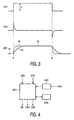
- Fig. 3 shows waveforms elucidating the operation of the embodiment of the backlighting unit in accordance with the invention.
- Fig. 3 shows the enhancement control signal ECS, the differentiated control signal CCS, and the brightness LBR of the lamp BLL.
- the enhancement control signal ECS which in this situation is the brightness control signal BCS has a value indicating a first brightness level (no enhancement is required).
- the enhancement control signal ECS is zero and the brightness LBR has a level B 1.
- the enhancement control signal ECS makes a jump J to a value indicating a second brightness level (the enhancement, which is in this example a higher brightness).
- the differentiated control signal CCS stays zero, it takes a considerable amount of time before the brightness LBR reaches the second level B2, as is shown by the waveform UB.
- the differentiated control signal CCS shows a differentiated enhancement control signal ECS.
- the differentiated control signal CCS which is the differentiated enhancement control signal ECS shows a spike. The spike causes a corresponding spike in the current IL through the lamp BLL and the second brightness level will be reached much faster as is shown by the partly dashed waveform BO.
- the brightness LBR of the lamp BLL is decreased within a short time.
- the enhancement control signal ECS is the brightness control signal BCS
- the steady state brightness of the lamp BLL is increased by increasing the duty cycle.
- the fast transition in the light output is obtained by temporary boosting the current IL through the lamp BLL.
- Fig. 4 shows another embodiment of the backlighting unit in accordance with the invention.
- a microcontroller MCU receives the enhancement control signal ECS separately or retrieves it from the display signal DS.
- the microcontroller MCU generates the brightness control signal BCS, or, as shown, directly the pulse width control signal PWC and the current control signal CSS.
- the current control signal usually is an analog signal and can be easily be obtained by filtering a high frequency pulse width modulated signal generated by the microcontroller MCU.
- the microcontroller MCU has an input to receive physical parameters PHP like the panel or/and the lamp temperature, and/or the behavior of the LCD cells.
- the microcontroller MCU may receive the feedback signal FBS and supply the error signal ES.
- the microcontroller MCU may receive the feedback signal FBS and supply the error signal ES.
- ADC analog to digital converter
- the microcontroller MCU knows the physical parameters PHP of the whole system. These parameters PHP can differ among different manufactured monitors even if assembled with same components due to the spreading of the nominal values. Preferably, the parameters PHP are measured at the final stage of the manufacturing process and stored in a memory storage device MEM which may be embedded in the microcontroller MCU. When the MCU recognizes that the brightness has to be changed from one value to another it generates the proper pulse width control signal PWC and the current control signal CSS in order to meet the transmission variation of the LCD cells. These signals generated by the microcontroller MCU will depend on the desired brightness jump, and may be related to the parameters PHP received by the MCU.
- the lamp BLL may be a single lamp, or a may comprise multiple lamps.
- the feedback element FN may be a current transformer. It is possible to highlight several areas. The areas may have a non rectangular shape.
- any reference signs placed between parentheses shall not be construed as limiting the claim.
- the word “comprising” does not exclude the presence of other elements or steps than those listed in a claim.
- the word "a” or “an” preceding an element does not exclude the presence of a plurality of such elements.
- the invention can be implemented by means of hardware comprising several distinct elements, and by means of a suitably programmed computer. In the device claim enumerating several means, several of these means can be embodied by one and the same item of hardware. The mere fact that certain measures are recited in mutually different dependent claims does not indicate that a combination of these measures cannot be used to advantage.
Landscapes
- Engineering & Computer Science (AREA)
- Physics & Mathematics (AREA)
- Computer Hardware Design (AREA)
- General Physics & Mathematics (AREA)
- Theoretical Computer Science (AREA)
- Chemical & Material Sciences (AREA)
- Crystallography & Structural Chemistry (AREA)
- Liquid Crystal Display Device Control (AREA)
- Control Of Indicators Other Than Cathode Ray Tubes (AREA)
- Liquid Crystal (AREA)
Claims (9)
- Dispositif d'affichage comprenant
un afficheur à cristaux liquides (LCD),
une unité de rétroéclairage (BLU) dotée d'une lampe de rétroéclairage (BLL) apte à produire de la lumière pour éclairer l'afficheur à cristaux liquides (LCD),
un circuit de commande de lampe (LDC) apte à commander la lampe de rétroéclairage (BLL) pour modifier une propriété de la lumière émise lorsqu'un signal de contrôle d'augmentation (ECS) indique qu'une augmentation est nécessaire dans une zone prédéterminée (PA) de l'afficheur à cristaux liquides, et
un contrôleur de signal (SCO) apte à recevoir un signal d'affichage (DS) et le signal de contrôle d'augmentation (ECS) pour fournir un signal d'affichage adapté (ADS) à l'afficheur à cristaux liquides (LCD) pour obtenir une transmission adaptée à l'extérieur de ladite zone prédéterminée (PA) de l'afficheur à cristaux liquides (LCD), caractérisé en ce que
le circuit de commande de la lampe (LDC) comprend un contrôleur de commande de lampe (BO) apte à recevoir le signal de contrôle d'augmentation (ECS) pour fournir temporairement un courant d'addition ou de soustraction à travers la lampe de rétroéclairage (BLL) pour faire correspondre la modification de la propriété de la lumière à une transmission adaptée de l'afficheur à cristaux liquides (LCD) de manière à obtenir un affichage sensiblement inchangé du signal d'affichage (DS) à l'extérieur de la zone prédéterminée (PA) lorsque le signal de contrôle d'augmentation (ECS) indique que l'augmentation est nécessaire. - Dispositif d'affichage selon la revendication 1, caractérisé en ce que la propriété de la lumière est sa brillance, et en ce que le circuit de commande de la lampe (LDC) comprend un générateur de courant (CUD) destiné à produire un courant (IL) à travers la lampe de rétroéclairage (BLL), et en ce que le contrôleur de commande de la lampe (BO) comprend des moyens (DIF) destinés à fournir un signal de contrôle de courant (CCS) au générateur de courant (CUD) pour adapter le courant (IL) traversant la lampe de rétroéclairage (BLL) lorsque le signal de contrôle d'augmentation (ECS) indique une augmentation nécessaire de la brillance de la zone prédéterminée (PA).
- Dispositif d'affichage selon la revendication 2, caractérisé en ce que le circuit de commande de la lampe (LDC) comprend :un modulateur de largeur d'impulsion (PWM) destiné à produire un signal de contrôle de largeur d'impulsion (PWC) dont le facteur de charge est fonction d'un signal de contrôle de brillance contrôlé par l'utilisateur (BCS),un agencement en série d'un dispositif de commande de courant (CUD), d'un dispositif de commutation (CSW) et de la lampe de rétroéclairage (BLL), le dispositif de commande de courant (CUD) ayant une entrée destinée à recevoir un signal d'entrée (ES) et une sortie destinée à fournir un courant prédéterminé (IL) à la lampe de rétroéclairage (BLL) lorsque le dispositif de commutation (CSW) est fermé, le dispositif de commutation (CSW) ayant une entrée de contrôle destinée à recevoir le signal de contrôle de largeur d'impulsion (PWC) pour déterminer les temps de marche et d'arrêt du dispositif de commutation (CSW), etle contrôleur de commande de la lampe (BO) comprend en outre un différentiateur (DIF) destiné à différencier le signal de contrôle d'augmentation (ECS) pour obtenir un signal de contrôle différencié (CCS), et un additionneur (AD) destiné à ajouter le signal de contrôle différencié (CCS) à un signal de contrôle de courant (CSS) pour fournir le signal d'entrée (ES).
- Système comprenant :le dispositif d'affichage (DAP) selon la revendication 1, etun ordinateur (COM) destiné à produire le signal d'affichage (DS) et le signal de contrôle d'augmentation (ECS) indiquant l'augmentation nécessaire du signal d'affichage (DS) dans la zone prédéterminée (PA) de l'écran d'affichage du dispositif d'affichage (DAP).
- Système selon la revendication 4, caractérisé en ce que la propriété de la lumière est sa brillance.
- Système selon la revendication 5, caractérisé en ce que le circuit de commande de la lampe (LDC) comprend un générateur de courant (CUD) destiné à produire un courant (IL) à travers la lampe de rétroéclairage (BLL), et en ce que le contrôleur de commande de la lampe (BO) comprend des moyens (DIF) destinés à fournir un signal de contrôle de courant (CCS) au générateur de courant (CUD) pour adapter le courant (IL) traversant la lampe de rétroéclairage (BLL) lorsque le signal de contrôle d'augmentation (ECS) indique une augmentation nécessaire de la brillance de la zone prédéterminée (PA).
- Système selon la revendication 5, caractérisé en ce que le circuit de commande de la lampe (LDC) comprend :un modulateur de largeur d'impulsion (PWM) destiné à produire un signal de contrôle de largeur d'impulsion (PWC) dont le facteur de charge est fonction d'un signal de contrôle de brillance contrôlé par l'utilisateur (BCS),un agencement en série d'un dispositif de commande de courant (CUD), d'un dispositif de commutation (CSW) et de la lampe de rétroéclairage (BLL), le dispositif de commande de courant (CUD) ayant une entrée destinée à recevoir un signal d'entrée (ES) et une sortie destinée à fournir un courant prédéterminé (IL) à la lampe de rétroéclairage (BLL) lorsque le dispositif de commutation (CSW) est fermé, le dispositif de commutation (CSW) ayant une entrée de contrôle destinée à recevoir le signal de contrôle de largeur d'impulsion (PWC) pour déterminer les temps de marche et d'arrêt du dispositif de commutation (CSW), etle contrôleur de commande de la lampe (BO) comprend en outre un différentiateur (DIF) destiné à différencier le signal de contrôle d'augmentation (ECS) pour obtenir un signal de contrôle différencié (CCS) et un additionneur (AD) destiné à ajouter le signal de contrôle différencié (CCS) à un signal de contrôle de courant (CSS) pour fournir le signal d'entrée (ES).
- Système selon la revendication 5, caractérisé en ce que le circuit de commande de la lampe (LDC) comprend un microcontrôleur (MCU) destiné à recevoir un paramètre physique (PHP) représentatif du comportement de transmission de l'afficheur à cristaux liquides (LCD) et/ou de l'émission de lumière de la lampe (BLL) pour déterminer le signal de contrôle de courant (CCS) et/ou le signal de contrôle de largeur d'impulsion (PWC).
- Système selon la revendication 5, caractérisé en ce que le circuit de commande de la lampe (LDC) comprend un microcontrôleur (MCU) et une mémoire (MEM) comprenant des données enregistrées d'un paramètre physique (PHP) représentatif du comportement de transmission de l'afficheur à cristaux liquides (LCD) et/ou de l'émission de lumière de la lampe (BLL).
Priority Applications (1)
| Application Number | Priority Date | Filing Date | Title |
|---|---|---|---|
| EP03704931A EP1500075B1 (fr) | 2002-04-02 | 2003-03-11 | Augmentation de la brillance d'une fenetre dans un afficheur a cristaux liquides |
Applications Claiming Priority (4)
| Application Number | Priority Date | Filing Date | Title |
|---|---|---|---|
| EP02076304 | 2002-04-02 | ||
| EP02076304 | 2002-04-02 | ||
| EP03704931A EP1500075B1 (fr) | 2002-04-02 | 2003-03-11 | Augmentation de la brillance d'une fenetre dans un afficheur a cristaux liquides |
| PCT/IB2003/000933 WO2003083817A1 (fr) | 2002-04-02 | 2003-03-11 | Augmentation de la brillance d'une fenetre dans un afficheur a cristaux liquides |
Publications (2)
| Publication Number | Publication Date |
|---|---|
| EP1500075A1 EP1500075A1 (fr) | 2005-01-26 |
| EP1500075B1 true EP1500075B1 (fr) | 2010-10-13 |
Family
ID=28459548
Family Applications (1)
| Application Number | Title | Priority Date | Filing Date |
|---|---|---|---|
| EP03704931A Expired - Lifetime EP1500075B1 (fr) | 2002-04-02 | 2003-03-11 | Augmentation de la brillance d'une fenetre dans un afficheur a cristaux liquides |
Country Status (9)
| Country | Link |
|---|---|
| US (1) | US7205974B2 (fr) |
| EP (1) | EP1500075B1 (fr) |
| JP (1) | JP4751020B2 (fr) |
| CN (1) | CN100426363C (fr) |
| AT (1) | ATE484816T1 (fr) |
| AU (1) | AU2003207928A1 (fr) |
| DE (1) | DE60334537D1 (fr) |
| ES (1) | ES2353861T3 (fr) |
| WO (1) | WO2003083817A1 (fr) |
Families Citing this family (11)
| Publication number | Priority date | Publication date | Assignee | Title |
|---|---|---|---|---|
| CN1647149A (zh) * | 2002-04-02 | 2005-07-27 | 皇家飞利浦电子股份有限公司 | 用于液晶显示的窗口亮度增强 |
| JP2006041832A (ja) * | 2004-07-26 | 2006-02-09 | Nec Saitama Ltd | 表示部照明の切り替え機能付き携帯無線端末 |
| DE102008048447A1 (de) | 2008-09-23 | 2010-04-29 | Siemens Enterprise Communications Gmbh & Co. Kg | Verfahren und Anordnung zur bildgebenden Darstellung von Information, insbesondere für den Einsatz bei Kommunikationsendgeräten |
| JP4710980B2 (ja) * | 2009-01-16 | 2011-06-29 | 株式会社デンソー | 表示装置 |
| WO2011132236A1 (fr) * | 2010-04-23 | 2011-10-27 | Necディスプレイソリューションズ株式会社 | Dispositif d'affichage, procédé d'affichage et programme |
| JP5780614B2 (ja) * | 2011-05-31 | 2015-09-16 | Necディスプレイソリューションズ株式会社 | 表示装置、表示方法 |
| WO2012164688A1 (fr) * | 2011-05-31 | 2012-12-06 | Necディスプレイソリューションズ株式会社 | Dispositif d'affichage et procédé d'affichage |
| KR101974366B1 (ko) * | 2012-02-10 | 2019-05-03 | 삼성전자주식회사 | 디지털 정보 디스플레이 장치에서 영상 내 각 객체에 대한 부가 정보를 제공하기 위한 방법 및 이를 위한 디지털 정보 디스플레이 장치 그리고 상기 부가 정보를 제공받는 가시광 통신 단말 |
| CN102968942B (zh) * | 2012-11-02 | 2016-05-04 | 京东方科技集团股份有限公司 | 面板暗点检测电路 |
| KR20150049045A (ko) * | 2013-10-29 | 2015-05-08 | 삼성전자주식회사 | 휴대단말에서 화면 밝기를 제어하는 방법 및 장치 |
| US20250201211A1 (en) * | 2022-03-21 | 2025-06-19 | Hewlett-Packard Development Company, L.P. | User selected display panel adjustment |
Family Cites Families (17)
| Publication number | Priority date | Publication date | Assignee | Title |
|---|---|---|---|---|
| US4928181A (en) * | 1988-11-21 | 1990-05-22 | Philip Morris Incorporated | Methods and apparatus for optically enhancing selected features in an input image |
| US5751261A (en) * | 1990-12-31 | 1998-05-12 | Kopin Corporation | Control system for display panels |
| US5479187A (en) * | 1994-02-23 | 1995-12-26 | Chunghwa Picture Tubes, Ltd. | Vertically scanned narrow light beam source for LCD display |
| US5592193A (en) * | 1994-03-10 | 1997-01-07 | Chunghwa Picture Tubes, Ltd. | Backlighting arrangement for LCD display panel |
| US5978041A (en) * | 1994-10-24 | 1999-11-02 | Hitachi, Ltd. | Image display system |
| US6094185A (en) * | 1995-07-05 | 2000-07-25 | Sun Microsystems, Inc. | Apparatus and method for automatically adjusting computer display parameters in response to ambient light and user preferences |
| KR0182940B1 (ko) * | 1995-11-28 | 1999-05-01 | 김광호 | 화면의 특정부분 칼라링 장치 및 방법 |
| US5933130A (en) * | 1996-07-26 | 1999-08-03 | Wagner; Roger | Anti-eye strain apparatus and method |
| JP3334535B2 (ja) * | 1997-01-29 | 2002-10-15 | 株式会社日立製作所 | 画像表示装置及び画像表示方法 |
| JP2891955B2 (ja) * | 1997-02-14 | 1999-05-17 | 日本電気移動通信株式会社 | Lcd表示装置 |
| US5894298A (en) * | 1997-03-14 | 1999-04-13 | Northern Telecom Limited | Display apparatus |
| US6239773B1 (en) * | 1997-10-13 | 2001-05-29 | U.S. Philips Corporation | Image display device |
| JP3047885B2 (ja) * | 1998-04-09 | 2000-06-05 | 日本電気株式会社 | バックライト制御装置およびバックライト制御方法 |
| JP2000287035A (ja) * | 1999-03-30 | 2000-10-13 | Nec Corp | 光源制御装置 |
| JP2003515775A (ja) * | 1999-12-02 | 2003-05-07 | コーニンクレッカ フィリップス エレクトロニクス エヌ ヴィ | ディスプレイスクリーンの選択された部分をハイライトする装置及び方法 |
| JP2003050569A (ja) * | 2000-11-30 | 2003-02-21 | Hitachi Ltd | 液晶表示装置 |
| TW548964B (en) * | 2001-01-24 | 2003-08-21 | Koninkl Philips Electronics Nv | Window brightness enhancement for LCD display |
-
2003
- 2003-03-11 CN CNB038076101A patent/CN100426363C/zh not_active Expired - Lifetime
- 2003-03-11 DE DE60334537T patent/DE60334537D1/de not_active Expired - Lifetime
- 2003-03-11 AT AT03704931T patent/ATE484816T1/de not_active IP Right Cessation
- 2003-03-11 WO PCT/IB2003/000933 patent/WO2003083817A1/fr not_active Ceased
- 2003-03-11 EP EP03704931A patent/EP1500075B1/fr not_active Expired - Lifetime
- 2003-03-11 US US10/509,452 patent/US7205974B2/en not_active Expired - Lifetime
- 2003-03-11 AU AU2003207928A patent/AU2003207928A1/en not_active Abandoned
- 2003-03-11 JP JP2003581159A patent/JP4751020B2/ja not_active Expired - Lifetime
- 2003-03-11 ES ES03704931T patent/ES2353861T3/es not_active Expired - Lifetime
Also Published As
| Publication number | Publication date |
|---|---|
| JP4751020B2 (ja) | 2011-08-17 |
| ATE484816T1 (de) | 2010-10-15 |
| AU2003207928A1 (en) | 2003-10-13 |
| WO2003083817A1 (fr) | 2003-10-09 |
| EP1500075A1 (fr) | 2005-01-26 |
| DE60334537D1 (de) | 2010-11-25 |
| US20050219198A1 (en) | 2005-10-06 |
| CN100426363C (zh) | 2008-10-15 |
| JP2005521905A (ja) | 2005-07-21 |
| US7205974B2 (en) | 2007-04-17 |
| ES2353861T3 (es) | 2011-03-07 |
| CN1647148A (zh) | 2005-07-27 |
Similar Documents
| Publication | Publication Date | Title |
|---|---|---|
| US6150772A (en) | Gas discharge lamp controller | |
| EP2149872B1 (fr) | Procédé et appareil de commande d'un ensemble de rétroéclairage | |
| US7633233B2 (en) | Digital control system for LCD backlights | |
| US7164409B2 (en) | Window brightness enhancement for LC display | |
| US7903081B2 (en) | Backlight driver, display apparatus having the same and method of driving backlight | |
| JP2007511061A (ja) | 発光機器アレイの電力効率最適化の方法と装置 | |
| US7205974B2 (en) | Window brightness enhancement for lc display | |
| JP2011139626A (ja) | Dc−dcコンバータ及びその制御方法 | |
| US20040001076A1 (en) | Method and apparatus for adjusting brightness of an LCD display | |
| EP1830609A2 (fr) | Appareil d'éclairage de lampe de décharge | |
| JP3076184B2 (ja) | 液晶表示装置 | |
| KR100497372B1 (ko) | 엘씨디 모니터에서 휘도 제어 방법 및 그 장치 | |
| JP7778481B2 (ja) | 光源の調光装置 | |
| JP2010164940A (ja) | 走査型バックライトlcd用のバックライトモジュール | |
| KR100764818B1 (ko) | 인버터의 버스트 디밍 주파수 최적화회로 | |
| JP2018101805A (ja) | Led駆動回路,led駆動方法、および液晶表示装置 | |
| JP2002359098A (ja) | Lcdのバックライト装置 | |
| KR20070005219A (ko) | 액정표시장치 | |
| JP2008010326A (ja) | 表示器の調光装置 | |
| JPH03296715A (ja) | 液晶装置 | |
| KR20080022798A (ko) | 백라이트 구동장치 및 이를 갖는 표시장치 |
Legal Events
| Date | Code | Title | Description |
|---|---|---|---|
| PUAI | Public reference made under article 153(3) epc to a published international application that has entered the european phase |
Free format text: ORIGINAL CODE: 0009012 |
|
| 17P | Request for examination filed |
Effective date: 20041102 |
|
| AK | Designated contracting states |
Kind code of ref document: A1 Designated state(s): AT BE BG CH CY CZ DE DK EE ES FI FR GB GR HU IE IT LI LU MC NL PT RO SE SI SK TR |
|
| AX | Request for extension of the european patent |
Extension state: AL LT LV MK RO |
|
| 17Q | First examination report despatched |
Effective date: 20070530 |
|
| GRAC | Information related to communication of intention to grant a patent modified |
Free format text: ORIGINAL CODE: EPIDOSCIGR1 |
|
| GRAP | Despatch of communication of intention to grant a patent |
Free format text: ORIGINAL CODE: EPIDOSNIGR1 |
|
| RIN1 | Information on inventor provided before grant (corrected) |
Inventor name: PASQUALINI, GIUSEPPE Inventor name: CASALE, CARLO |
|
| GRAS | Grant fee paid |
Free format text: ORIGINAL CODE: EPIDOSNIGR3 |
|
| GRAA | (expected) grant |
Free format text: ORIGINAL CODE: 0009210 |
|
| AK | Designated contracting states |
Kind code of ref document: B1 Designated state(s): AT BE BG CH CY CZ DE DK EE ES FI FR GB GR HU IE IT LI LU MC NL PT RO SE SI SK TR |
|
| REG | Reference to a national code |
Ref country code: GB Ref legal event code: FG4D |
|
| REG | Reference to a national code |
Ref country code: CH Ref legal event code: EP |
|
| REG | Reference to a national code |
Ref country code: IE Ref legal event code: FG4D |
|
| REF | Corresponds to: |
Ref document number: 60334537 Country of ref document: DE Date of ref document: 20101125 Kind code of ref document: P |
|
| REG | Reference to a national code |
Ref country code: NL Ref legal event code: VDEP Effective date: 20101013 |
|
| REG | Reference to a national code |
Ref country code: ES Ref legal event code: FG2A Effective date: 20110223 |
|
| PG25 | Lapsed in a contracting state [announced via postgrant information from national office to epo] |
Ref country code: PT Free format text: LAPSE BECAUSE OF FAILURE TO SUBMIT A TRANSLATION OF THE DESCRIPTION OR TO PAY THE FEE WITHIN THE PRESCRIBED TIME-LIMIT Effective date: 20110214 Ref country code: SE Free format text: LAPSE BECAUSE OF FAILURE TO SUBMIT A TRANSLATION OF THE DESCRIPTION OR TO PAY THE FEE WITHIN THE PRESCRIBED TIME-LIMIT Effective date: 20101013 Ref country code: FI Free format text: LAPSE BECAUSE OF FAILURE TO SUBMIT A TRANSLATION OF THE DESCRIPTION OR TO PAY THE FEE WITHIN THE PRESCRIBED TIME-LIMIT Effective date: 20101013 Ref country code: BG Free format text: LAPSE BECAUSE OF FAILURE TO SUBMIT A TRANSLATION OF THE DESCRIPTION OR TO PAY THE FEE WITHIN THE PRESCRIBED TIME-LIMIT Effective date: 20110113 Ref country code: AT Free format text: LAPSE BECAUSE OF FAILURE TO SUBMIT A TRANSLATION OF THE DESCRIPTION OR TO PAY THE FEE WITHIN THE PRESCRIBED TIME-LIMIT Effective date: 20101013 Ref country code: SI Free format text: LAPSE BECAUSE OF FAILURE TO SUBMIT A TRANSLATION OF THE DESCRIPTION OR TO PAY THE FEE WITHIN THE PRESCRIBED TIME-LIMIT Effective date: 20101013 Ref country code: NL Free format text: LAPSE BECAUSE OF FAILURE TO SUBMIT A TRANSLATION OF THE DESCRIPTION OR TO PAY THE FEE WITHIN THE PRESCRIBED TIME-LIMIT Effective date: 20101013 |
|
| PG25 | Lapsed in a contracting state [announced via postgrant information from national office to epo] |
Ref country code: GR Free format text: LAPSE BECAUSE OF FAILURE TO SUBMIT A TRANSLATION OF THE DESCRIPTION OR TO PAY THE FEE WITHIN THE PRESCRIBED TIME-LIMIT Effective date: 20110114 Ref country code: BE Free format text: LAPSE BECAUSE OF FAILURE TO SUBMIT A TRANSLATION OF THE DESCRIPTION OR TO PAY THE FEE WITHIN THE PRESCRIBED TIME-LIMIT Effective date: 20101013 |
|
| PG25 | Lapsed in a contracting state [announced via postgrant information from national office to epo] |
Ref country code: CZ Free format text: LAPSE BECAUSE OF FAILURE TO SUBMIT A TRANSLATION OF THE DESCRIPTION OR TO PAY THE FEE WITHIN THE PRESCRIBED TIME-LIMIT Effective date: 20101013 Ref country code: EE Free format text: LAPSE BECAUSE OF FAILURE TO SUBMIT A TRANSLATION OF THE DESCRIPTION OR TO PAY THE FEE WITHIN THE PRESCRIBED TIME-LIMIT Effective date: 20101013 |
|
| PLBE | No opposition filed within time limit |
Free format text: ORIGINAL CODE: 0009261 |
|
| STAA | Information on the status of an ep patent application or granted ep patent |
Free format text: STATUS: NO OPPOSITION FILED WITHIN TIME LIMIT |
|
| PG25 | Lapsed in a contracting state [announced via postgrant information from national office to epo] |
Ref country code: RO Free format text: LAPSE BECAUSE OF FAILURE TO SUBMIT A TRANSLATION OF THE DESCRIPTION OR TO PAY THE FEE WITHIN THE PRESCRIBED TIME-LIMIT Effective date: 20101013 Ref country code: SK Free format text: LAPSE BECAUSE OF FAILURE TO SUBMIT A TRANSLATION OF THE DESCRIPTION OR TO PAY THE FEE WITHIN THE PRESCRIBED TIME-LIMIT Effective date: 20101013 Ref country code: DK Free format text: LAPSE BECAUSE OF FAILURE TO SUBMIT A TRANSLATION OF THE DESCRIPTION OR TO PAY THE FEE WITHIN THE PRESCRIBED TIME-LIMIT Effective date: 20101013 |
|
| 26N | No opposition filed |
Effective date: 20110714 |
|
| PG25 | Lapsed in a contracting state [announced via postgrant information from national office to epo] |
Ref country code: MC Free format text: LAPSE BECAUSE OF NON-PAYMENT OF DUE FEES Effective date: 20110331 |
|
| REG | Reference to a national code |
Ref country code: CH Ref legal event code: PL |
|
| REG | Reference to a national code |
Ref country code: DE Ref legal event code: R097 Ref document number: 60334537 Country of ref document: DE Effective date: 20110714 |
|
| REG | Reference to a national code |
Ref country code: IE Ref legal event code: MM4A |
|
| PG25 | Lapsed in a contracting state [announced via postgrant information from national office to epo] |
Ref country code: IE Free format text: LAPSE BECAUSE OF NON-PAYMENT OF DUE FEES Effective date: 20110311 Ref country code: LI Free format text: LAPSE BECAUSE OF NON-PAYMENT OF DUE FEES Effective date: 20110331 Ref country code: CH Free format text: LAPSE BECAUSE OF NON-PAYMENT OF DUE FEES Effective date: 20110331 |
|
| PG25 | Lapsed in a contracting state [announced via postgrant information from national office to epo] |
Ref country code: CY Free format text: LAPSE BECAUSE OF FAILURE TO SUBMIT A TRANSLATION OF THE DESCRIPTION OR TO PAY THE FEE WITHIN THE PRESCRIBED TIME-LIMIT Effective date: 20101013 Ref country code: LU Free format text: LAPSE BECAUSE OF NON-PAYMENT OF DUE FEES Effective date: 20110311 |
|
| PG25 | Lapsed in a contracting state [announced via postgrant information from national office to epo] |
Ref country code: TR Free format text: LAPSE BECAUSE OF FAILURE TO SUBMIT A TRANSLATION OF THE DESCRIPTION OR TO PAY THE FEE WITHIN THE PRESCRIBED TIME-LIMIT Effective date: 20101013 |
|
| PG25 | Lapsed in a contracting state [announced via postgrant information from national office to epo] |
Ref country code: HU Free format text: LAPSE BECAUSE OF FAILURE TO SUBMIT A TRANSLATION OF THE DESCRIPTION OR TO PAY THE FEE WITHIN THE PRESCRIBED TIME-LIMIT Effective date: 20101013 |
|
| REG | Reference to a national code |
Ref country code: ES Ref legal event code: PC2A Owner name: KONINKLIJKE PHILIPS N.V. Effective date: 20140221 |
|
| REG | Reference to a national code |
Ref country code: DE Ref legal event code: R082 Ref document number: 60334537 Country of ref document: DE Representative=s name: VOLMER, GEORG, DIPL.-ING., DE |
|
| REG | Reference to a national code |
Ref country code: DE Ref legal event code: R082 Ref document number: 60334537 Country of ref document: DE Representative=s name: VOLMER, GEORG, DIPL.-ING., DE Effective date: 20140328 Ref country code: DE Ref legal event code: R082 Ref document number: 60334537 Country of ref document: DE Representative=s name: MEISSNER, BOLTE & PARTNER GBR, DE Effective date: 20140328 Ref country code: DE Ref legal event code: R082 Ref document number: 60334537 Country of ref document: DE Representative=s name: MEISSNER BOLTE PATENTANWAELTE RECHTSANWAELTE P, DE Effective date: 20140328 Ref country code: DE Ref legal event code: R081 Ref document number: 60334537 Country of ref document: DE Owner name: KONINKLIJKE PHILIPS N.V., NL Free format text: FORMER OWNER: KONINKLIJKE PHILIPS ELECTRONICS N.V., EINDHOVEN, NL Effective date: 20140328 |
|
| REG | Reference to a national code |
Ref country code: FR Ref legal event code: CA Effective date: 20141126 Ref country code: FR Ref legal event code: CD Owner name: KONINKLIJKE PHILIPS ELECTRONICS N.V., NL Effective date: 20141126 |
|
| REG | Reference to a national code |
Ref country code: DE Ref legal event code: R082 Ref document number: 60334537 Country of ref document: DE Representative=s name: MEISSNER, BOLTE & PARTNER GBR, DE Ref country code: DE Ref legal event code: R082 Ref document number: 60334537 Country of ref document: DE Representative=s name: MEISSNER BOLTE PATENTANWAELTE RECHTSANWAELTE P, DE |
|
| REG | Reference to a national code |
Ref country code: FR Ref legal event code: PLFP Year of fee payment: 14 |
|
| PG25 | Lapsed in a contracting state [announced via postgrant information from national office to epo] |
Ref country code: IT Free format text: LAPSE BECAUSE OF NON-PAYMENT OF DUE FEES Effective date: 20160311 |
|
| REG | Reference to a national code |
Ref country code: FR Ref legal event code: PLFP Year of fee payment: 15 |
|
| PG25 | Lapsed in a contracting state [announced via postgrant information from national office to epo] |
Ref country code: IT Free format text: LAPSE BECAUSE OF NON-PAYMENT OF DUE FEES Effective date: 20160311 |
|
| PGRI | Patent reinstated in contracting state [announced from national office to epo] |
Ref country code: IT Effective date: 20170710 |
|
| REG | Reference to a national code |
Ref country code: FR Ref legal event code: PLFP Year of fee payment: 16 |
|
| PGFP | Annual fee paid to national office [announced via postgrant information from national office to epo] |
Ref country code: GB Payment date: 20220322 Year of fee payment: 20 Ref country code: DE Payment date: 20220329 Year of fee payment: 20 |
|
| PGFP | Annual fee paid to national office [announced via postgrant information from national office to epo] |
Ref country code: IT Payment date: 20220323 Year of fee payment: 20 Ref country code: FR Payment date: 20220325 Year of fee payment: 20 |
|
| PGFP | Annual fee paid to national office [announced via postgrant information from national office to epo] |
Ref country code: ES Payment date: 20220418 Year of fee payment: 20 |
|
| REG | Reference to a national code |
Ref country code: DE Ref legal event code: R071 Ref document number: 60334537 Country of ref document: DE |
|
| REG | Reference to a national code |
Ref country code: GB Ref legal event code: PE20 Expiry date: 20230310 |
|
| REG | Reference to a national code |
Ref country code: ES Ref legal event code: FD2A Effective date: 20230505 |
|
| PG25 | Lapsed in a contracting state [announced via postgrant information from national office to epo] |
Ref country code: GB Free format text: LAPSE BECAUSE OF EXPIRATION OF PROTECTION Effective date: 20230310 |
|
| PG25 | Lapsed in a contracting state [announced via postgrant information from national office to epo] |
Ref country code: ES Free format text: LAPSE BECAUSE OF EXPIRATION OF PROTECTION Effective date: 20230312 |