BACKGROUND OF THE INVENTION
(1) Field of the Invention
The present invention relates to a method and an apparatus for
joining two substrates with an adhesive sheet interposed therebetween.
(2) Description of the Related Art
In a conventional semiconductor wafer (hereinafter, simply referred
to as "wafer"), a number of elements are formed on the wafer, the back side
of the wafer is ground in a back grinding process. After that, the resultant
wafer is cut into each element in a dicing process. It is recent trend,
however, to thin the wafer to as small as 100 µm to 50 µm, or even about 25
µm for conforming to the requirement of high density packaging.
Such a wafer that is made thinner in the back grinding process is
not only brittle but also has distortion; therefore, its handlability becomes
considerably poor.
In view of this, there has been suggested and practiced an approach
to enhance a wafer by joining the wafer and a glass plate or the like with an
adhesive sheet interposed therebetween.
To be more specific, a wafer having an adhesive tape previously
adhered to the upper face is mounted and fixed on a holding stage. At a
position above this wafer, a base formed of a glass plate or the like
(substrate in the present invention) is latched and held at an upper end of a
base supporting part in an inclined position. Then, a press roller moves on
the surface of the base supported in inclined position and, also, the base
supporting part moves downward according to the movement of the press
roller, so that the base is joined to the semiconductor wafer (see JP-A 2000-349136.)
In the above-described conventional substrate joining apparatus,
since the base for reinforcement is latched and held at the upper end of the
cylindrical base supporting part surrounding the wafer, the reinforcing base
has inevitably a larger diameter than the wafer. For this reason, the outer
circumference of the base partly protrudes from the outer circumference of
the wafer that has been reinforced by joining the base. This protrusion of
base hinders the subsequent process of the wafer and makes the apparatus
bulky.
SUMMARY OF THE INVENTION
The present invention is devised in consideration of the
aforementioned circumstances, and it is a primary object of the present
invention to provide a substrate joining method and a substrate joining
apparatus capable of joining a substrate such as semiconductor wafer to a
reinforcing substrate which is the same as or smaller than the substrate in
diameter, and miniaturizing the apparatus.
In order to achieve the object, the present invention employs the
following configurations.
The substrate joining method for joining two substrates to each
other with an adhesive sheet interposed therebetween comprises the
following step:
According to the substrate joining method of the present invention,
it is possible to continuously move the joining roller without hindered by the
holding means by retracting the holding means from the path of the joining
roller when the joining roller that is moving for achieving joining
approaches the holding points of the second substrate. Eventually, the
holding means is retracted from the path of the joining roller at all of the
holding positions. This enables a second substrate which is the same or
smaller than the first substrate in diameter to be held and joined, and the
second substrate can be joined without partly protruding from the first
substrate, so that the subsequent process can be conducted in the state
where there is no protrusion. This also contributes to miniaturize the
apparatus.
In the present invention, it is preferred that the holding means is
moved down with the movement of the joining roller.
According to this method, in the step of joining the second substrate
to the first substrate with the movement of the joining roller on the surface
of the second substrate while bending the second substrate from its one end,
the holding means of the second substrate is moved down so that the bend of
the second substrate falls within an acceptable range. In this manner, it is
possible to join the second substrate to the first substrate while preventing
the second substrate to be joined from being excessively bent and damaged.
Also according to the present invention, it is preferred that
appropriate resistance is given to the downward movement of the holding
means.
According to this method, when the holing means moves down in
accordance with the inclination of the second substrate, appropriate
resistance is given to the downward movement. This prevents the holding
means from moving down more than necessary due to inertia or the like.
Since the downward movement accompanies appropriate resistance,
oscillation will not occur more than necessary due to inertia or the like and
high supporting accuracy of the second substrate is achieved, which is
effective for improving the joining accuracy.
Furthermore, in the present invention, it is preferred that the
joining roller rolls at a circumferential velocity that is equal to a joining
forward movement velocity of the joining roller.
According to this method, it is possible to move the joining roller
without exerting any external power in the roller moving direction onto the
surface of the second substrate. Therefore, it is possible to improve the
joining accuracy of these substrates.
In the present invention, it is preferred that the first substrate and
the second substrate are joined to each other under reduced pressures.
According to this method, it is possible to join the first substrate and
the second substrate to each other while preventing bubbles from getting
contained in the joining surface. Therefore, it is possible to realize the
joining process with little occurrence of defective products.
Preferably, at least one of the first and second substrates is a
semiconductor wafer, for example, one of the first and second substrates is a
stainless sheet and the other is a semiconductor wafer.
Also, in order to achieve the above object, the present invention
employs the following constitutions.
A substrate joining apparatus for joining two substrates to each
other comprises:
According to the substrate joining apparatus of the present
invention, as the joining roller moves on the surface of the second substrate,
the second substrate is joined onto the first substrate while it is bent from
its one end. In this case, when the joining roller approaches a point where
the second substrate is held, the holding means at that point is retracted
from the path of the joining roller, so that the joining roller can continuously
move without hindered by the holding means. Eventually, holding means of
all holding points are retracted from the path of the joining roller. In this
manner, it is possible to desirably realize the first method invention.
Furthermore, in the present invention, it is preferred that the
driving means is configured to move up and down the holding means in
accordance with movement of the joining roller.
According to this configuration, in the course that second substrate
is joined with the first substrate while being bent from its one end, as the
joining roller moves on the surface of the second substrate, the holding
means of the second substrate is moved up and down so that the bend of the
second substrate falls within an acceptable range. Therefore, it is possible
to join the second substrate to the first substrate while preventing the
second substrate to be joined from being excessively bent and damaged.
Also in the present invention, it is preferred that the holding means
is made up of a center latch claw that latches a center end edge of roller
forward direction in the periphery of the second substrate and a pair of side
latch claws that latch the end edge on the right and left sides with respect to
the roller forward direction in the periphery of the second substrate, and at
least one of the center latch claw and the side latch claws is allowed to
oscillate about a lateral fulcrum crossing at right angles with the roller
forward direction.
According to this configuration, the second substrate before
subjected to joining is placed so as to oppose to the first substrate at a
certain distance while being latched at three points by the center latch claw
and the right and left side latch claws. When the joining operation starts,
the joining roller pushes one end portion of the second substrate against one
end portion of the first substrate and then the joining roller moves on the
surface of the second substrate, whereby the second substrate is joined to
the first substrate while being bent from its one end.
In this case, since the second substrate is bent and deformed within
an acceptable range by the movement of the joining roller, the portion of the
substrate that has not been joined is inclined to rise in the roller forward
direction. In respect of this, if the side latch claws are allowed to oscillate
by latching the side latch claws to the second substrate while keeping a
large width in the circumferential direction of the substrate, the side latch
claws can oscillate so as to conform with the inclination of the substrate.
Also, if the center latch claw is allowed to oscillate, the side latch
claws can oscillate so as to conform with the inclination of the substrate
when the joining roller approaches the center latch claw.
That is, it is possible to latch and support the second substrate
having inclination due to bending deformation caused by the joining
operation in such a posture that conforms with the inclination, and hence it
is possible to prevent the substrate from being damaged at the latched and
held points.
Also, in the present invention, it is preferred that appropriate
resistance is given to rotation of the center latch claw and the side latch
claws.
According to this configuration, since appropriate resistance is given
to oscillation when the side latch claws or the center latch claw oscillate in
conformance with the inclination of the second substrate, it is possible to
prevent the latch claws from oscillating more than necessary due to inertia
or the like. Since appropriate resistance is exerted on the oscillation,
oscillation more than necessary due to inertia or the like does not occur and
high supporting accuracy of the second substrate is achieved, which is
effective for improving the joining accuracy.
In the present invention, it is preferred that the holding means is
made up of an adsorption nozzle that adsorbs to and holds the surface on
the side of center end edge in the roller forward direction in the periphery of
the second substrate and a pair of adsorption nozzles that adsorb to and
hold the end edge sides of the right and left sides with respect to the roller
forward direction in the periphery of the second substrate, and at least one
of the center adsorption nozzle and the side adsorption nozzles is moved
down.
According to this configuration, the second substrate before joining
is placed so as to oppose to the first substrate at a certain distance while
adsorbed at three points by the adsorption nozzles. When the joining
operation starts, the joining roller pushes one end portion of the second
substrate against one end portion of the first substrate and then the joining
roller moves on the surface of the second substrate, whereby the second
substrate is joined onto the first substrate while being bent from its one end.
In this case, the second substrate is bent and deformed within an
acceptable range by the movement of the joining roller, and the portion of
the substrate that has not been joined is inclined to rise in the roller
forward direction. In respect of this, if the adsorption nozzles are able to
move down, the side adsorption nozzles can move down so as to conform
with the inclination of the substrate.
Also, if the center adsorption nozzle is able to move down, the side
adsorption nozzles can move down so as to conform with the inclination of
the substrate when the joining roller approaches the center adsorption
nozzle.
That is, it is possible to adsorb and hold the second substrate which
inclines due to bending deformation.caused by the joining operation in such
a posture that conforms with the inclination, and hence it is possible to
prevent the substrate from being damaged at the adsorbed and held points.
Also, in the present invention, it is preferred that appropriate
resistance is given to downward movement of the center latch claw and the
side latch claws.
According to this configuration, since appropriate resistance is given
to downward movement when the side adsorption nozzles or the center
adsorption nozzle move down in conformance with the inclination of the
second substrate, it is possible to prevent the adsorption nozzles from
moving down more than necessary due to inertia or the like. Since
appropriate resistance is exerted on the downward movement, downward
movement more than necessary due to inertia or the like does not occur and
high supporting accuracy of the second substrate is achieved, which is
effective for improving the joining accuracy.
In the present invention, it is preferred that the joining roller is
driven at a circumferential velocity that is equal to the joining forward
movement velocity.
According to this configuration, it is possible to move the joining
roller without exerting any external power of the roller moving direction on
the surface of the second substrate. Therefore, it is possible to improve the
joining accuracy of these substrates.
In the present invention, it is preferred that heating means is
incorporated in the holding table.
According to this configuration, since the heating means is
incorporated in the holding means, it is possible to soften the adhesive of the
adhesive sheet adhered to the substrate, and hence join the substrates with
high efficiency.
In the present invention, it is preferred that the holding table, the
holding means and the joining roller are accommodated in a decompression
chamber.
According to this configuration, it is possible to join the first
substrate and the second substrate to each other while preventing bubbles
from getting contained in the joining surface. Therefore, it is possible to
realize the joining process with little occurrence of defective products.
BRIEF DESCRIPTION OF THE DRAWINGS
For the purpose of illustrating the invention, there are shown in the
drawings several forms which are presently preferred, it being understood,
however, that the invention is not limited to the precise arrangement and
instrumentalities shown.
DESCRIPTION OF THE PREFERRED EMBODIMENTS
An embodiment of the present invention will now be explained with
reference to the drawings.
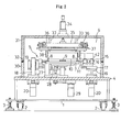
Fig. 1 is a plan view of a substrate joining apparatus for
implementing a substrate joining method of the present invention, and Fig.
2 is a front view thereof.
As shown in Fig. 4, the substrate joining apparatus according to the
present embodiment is configured to join a reinforcing substrate w2 formed
of glass plate serving as a second substrate on a semiconductor wafer
(hereinafter, simply referred to as "wafer") w1 serving as a first substrate.
Basically, as shown in Figs. 1 and 2, a stage frame 4 is disposed on the
upper face of a base frame 1 equipped with caster wheels 2 for movement
and stands 3 for fixing, and a joining mechanism 5 and an openable/closable
decompression chamber 6 accommodating the same are disposed on the
stage frame 4.
The joining mechanism 5 includes a holding table 7 of vacuum
adsorption type on which the wafer w1 is horizontally mounted and held, a
pair of right and left side latch claws 8 and a center latch claw 9 that latch
and hold the periphery of the reinforcing substrate w2 at three points, a
joining roller 10 that is horizontally hung in the right and left direction and
moves fore-and-aft direction, and driving means for these. Concrete
structures of each part will be explained below.
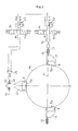
As shown in Fig. 3, the side latch claws 8 are bolted to a holder 11 in
a detachable manner, and are formed stepwise at their tip ends with a latch
portion 8a of a partial arc shape that receives and latches a right and left
opposing portion in the periphery of the reinforcing substrate w2 from
beneath. This latch portion 8a is formed over a certain range in the
circumferential direction from right and left diagonal positions passing
through the center of the substrate to a starting end side of the joining
(lower side in Fig. 3).
The holder 11 itself is born on a bearing bracket 12 so as to be able
to oscillate about a horizontal lateral axial center x1 passing through the
center of the substrate in plane view, and a supporting axis 13 rotatably
supported by the bearing bracket 12 is connected to an air-driven rotary
actuator 15 via an electromagnetic valve 14. The holder 11 is allowed to
oscillate only from the horizontal posture to the front down posture, and
when the electromagnetic valve 14 is in a neutral position "n" as illustrated,
the rotary actuator 15 can freely rotate. When the electromagnetic valve 14
is switched to a first position p1, the rotary actuator 15 drives the holder 11
into the front rising direction, so that the holder 11 and the side latch claws
8 attached thereto are forcedly held in the horizontal posture which is an
oscillation limit in the front rising direction.
Again referring to Figs. 1 and 2, the bearing bracket 12 bearing the
holder 11 of either right or left side latch claw 8 and the rotary actuator 15
are mounted on a supporting stage 16, and the supporting stage 16 is
designed to be laterally movable in the horizontal direction via a linear
lateral driving mechanism 17 driven in a screw feeding manner by an air
cylinder or a pulse motor. In other words, the right and left side latch claws
8 are reciprocable between the substrate holding position and the retracted
position retracted outside the substrate.
Furthermore, the linear lateral driving mechanism 17 itself is
mounted on an elevator stage 19 which is able to move up and down along a
rail 18 erected on the stage frame 4, and by moving up and down the
elevator stage 19 in a screw feeding manner by means of a pulse motor 20, it
is possible to move up and down the right and the left side latch claws 8
respectively as desired.
The center latch claw 9 is also bolted to a holder 21 in a detachable
manner as shown in Fig. 3, and formed stepwise at its tip end with a latch
portion 9a of a partial arc shape that receives and latches an edge end on
the joining end side of the reinforcing substrate w2 from beneath over a
certain range in the circumferential direction.
The holder 21 itself is born on a bearing bracket 22 so as to be able
to oscillate about a horizontal lateral axial center x2 in plane view, and a
supporting axis 23 rotatably supported by the bearing bracket 22 is
connected to an air-driven rotary actuator 25 via an electromagnetic valve
24. The holder 21 is allowed to oscillate only from the horizontal posture to
the front down position. When the electromagnetic valve 24 is in a neutral
position "n" as illustrated, the rotary actuator 25 can freely rotate, and
when the electromagnetic valve 24 is switched to a first position p1, the
rotary actuator 25 drives the holder 21 into the front rising direction, so that
the holder 21 and the center latch claw 9 attached thereto are forcedly held
in the horizontal posture which is the oscillation limit in the front rising
direction.
The bearing bracket 22 bearing the holder 21 of the center latch
claw 9 and the rotary actuator 25 are also mounted on a supporting stage
26, and the supporting stage 26 is designed to be movable in the fore-and-aft
direction via a linear fore-and-aft driving mechanism (not shown) driven in
a screw feeding manner by an air cylinder or a pulse motor. In other words,
the center latch claw 9 is reciprocable between the substrate holding
position and the retracted position retracted outside the substrate.
Furthermore, as seen from Fig. 2, the linear fore-and-aft driving
mechanism itself is mounted on an elevator stage 28 which is able to move
up and down along a rail 27 erected on the stage frame 4, and by moving up
and down the elevator stage 28 in a screw feeding manner by means of a
pulse motor 29, it is possible to move up and down the center latch claw 9 as
desired.
The decompression chamber 6 is made up of a fixed peripheral wall
30 of rectangular cylinder shape provided on the stage frame 4 and a cover
case 31 attached to the fixed peripheral wall 30 via a hinge (not shown) so
as to be able to open/close by oscillation in the vertical direction. Thus, the
internal pressure of the decompression chamber 6 can be reduced by
actuating a vacuum pump (not shown). The entire circumference of the
upper end of the fixed peripheral wall 30 is attached with a seal 32 for
ensuring closeness of the interior by close contact with the entire
circumference of the lower end of the closed cover case 31.
The joining roller 10 is provided in the cover case 31 so as to be
movable in the fore-and-aft direction and in the up and down direction. To
be more specific, the cover case 31 is attached with an elevator frame 35
which is slidable in the up and down direction via four guide axes 33 and is
driven to move up and down by the air cylinder 34. That is, as to the joining
roller 10, a movable stage 37 is attached so as to be movable in the fore-and-aft
direction along a pair of right and left guide axes 36 that are hung by
elevator frame 35 horizontally in the fore-and-aft direction; and the joining
roller 10 is rotatably supported horizontally in the right and left direction by
a holder 38 that is connected by bolting to the bottom face of the movable
stage 37 in a detachable manner.
On the right and left sides of the elevator frame 35, a non-slip type
belt 41 that is to be rotationally driven by the motor 40 is horizontally
wound in the fore-and-aft direction. To this belt 41 is connected the
movable stage 37, and by driving the movable stage 37 to move horizontally
in the fore-and-aft direction by rotating the belt 41 forward or backward, the
joining roller 10 is moved horizontally in the fore-and-aft direction.
The holder 38 of the joining roller 10 is provided with a motor 42 for
driving the joining roller 10, the motor 42 auto-rotating while moving the
joining roller 10 in the fore-and-aft direction.
Joining operations of the substrate joining apparatus having the
above configurations will be explained below based on Figs. 4 to 9.
This is the end of the one cycle of joining operation. The cycle of
operation is then repeated.
In the above joining apparatus, if the diameter of the substrate
changes, the holding table 7, the side latch claws 8, the center latch claw 9
and the joining roller 10 are also replaced by suitable ones.
Although the forward movement velocity of the joining roller 10 may
be usually constant, the area where the roller moves may be separated into
a plurality of sections, and the forward movement velocity may be changed
for each section.
In the above embodiment, the case where the reinforcing substrate
w2 having the same diameter as the wafer w1 is joined was taken as an
example, the same operation applies to the case where a reinforcing
substrate w2 having a slightly smaller diameter than the wafer w1 is joined.
Also a reinforcing substrate w2 having a larger diameter than the wafer w1
may be joined and, in this case, the side latch claws 8 and the center latch
claw 9 may be moved down so as to sink into notch recesses 7a, 7b formed
near the circumference of the holding table 7 rather than retracting the side
latch claws 8 and the center latch claw 9 outside the substrate.
Not limited to the above embodiment, the present invention may be
practiced in the following variants.
The present invention may be embodied in other specific forms
without departing from the spirit or essential attributes thereof and,
accordingly, reference should be made to the appended claims, rather than
to the foregoing specification, as indicating the scope of the invention.