EP1498603B1 - Kolben für eine Hochdruck-Kolben-Zylindereinheit eines Einspritzventils - Google Patents
Kolben für eine Hochdruck-Kolben-Zylindereinheit eines Einspritzventils Download PDFInfo
- Publication number
- EP1498603B1 EP1498603B1 EP04405372A EP04405372A EP1498603B1 EP 1498603 B1 EP1498603 B1 EP 1498603B1 EP 04405372 A EP04405372 A EP 04405372A EP 04405372 A EP04405372 A EP 04405372A EP 1498603 B1 EP1498603 B1 EP 1498603B1
- Authority
- EP
- European Patent Office
- Prior art keywords
- piston
- accordance
- cylinder unit
- injection
- control
- Prior art date
- Legal status (The legal status is an assumption and is not a legal conclusion. Google has not performed a legal analysis and makes no representation as to the accuracy of the status listed.)
- Expired - Lifetime
Links
Images

Classifications
-
- F—MECHANICAL ENGINEERING; LIGHTING; HEATING; WEAPONS; BLASTING
- F02—COMBUSTION ENGINES; HOT-GAS OR COMBUSTION-PRODUCT ENGINE PLANTS
- F02M—SUPPLYING COMBUSTION ENGINES IN GENERAL WITH COMBUSTIBLE MIXTURES OR CONSTITUENTS THEREOF
- F02M43/00—Fuel-injection apparatus operating simultaneously on two or more fuels, or on a liquid fuel and another liquid, e.g. the other liquid being an anti-knock additive
- F02M43/04—Injectors peculiar thereto
-
- F—MECHANICAL ENGINEERING; LIGHTING; HEATING; WEAPONS; BLASTING
- F02—COMBUSTION ENGINES; HOT-GAS OR COMBUSTION-PRODUCT ENGINE PLANTS
- F02M—SUPPLYING COMBUSTION ENGINES IN GENERAL WITH COMBUSTIBLE MIXTURES OR CONSTITUENTS THEREOF
- F02M61/00—Fuel-injectors not provided for in groups F02M39/00 - F02M57/00 or F02M67/00
- F02M61/16—Details not provided for in, or of interest apart from, the apparatus of groups F02M61/02 - F02M61/14
-
- F—MECHANICAL ENGINEERING; LIGHTING; HEATING; WEAPONS; BLASTING
- F02—COMBUSTION ENGINES; HOT-GAS OR COMBUSTION-PRODUCT ENGINE PLANTS
- F02M—SUPPLYING COMBUSTION ENGINES IN GENERAL WITH COMBUSTIBLE MIXTURES OR CONSTITUENTS THEREOF
- F02M63/00—Other fuel-injection apparatus having pertinent characteristics not provided for in groups F02M39/00 - F02M57/00 or F02M67/00; Details, component parts, or accessories of fuel-injection apparatus, not provided for in, or of interest apart from, the apparatus of groups F02M39/00 - F02M61/00 or F02M67/00; Combination of fuel pump with other devices, e.g. lubricating oil pump
- F02M63/02—Fuel-injection apparatus having several injectors fed by a common pumping element, or having several pumping elements feeding a common injector; Fuel-injection apparatus having provisions for cutting-out pumps, pumping elements, or injectors; Fuel-injection apparatus having provisions for variably interconnecting pumping elements and injectors alternatively
- F02M63/0225—Fuel-injection apparatus having a common rail feeding several injectors ; Means for varying pressure in common rails; Pumps feeding common rails
-
- F—MECHANICAL ENGINEERING; LIGHTING; HEATING; WEAPONS; BLASTING
- F02—COMBUSTION ENGINES; HOT-GAS OR COMBUSTION-PRODUCT ENGINE PLANTS
- F02M—SUPPLYING COMBUSTION ENGINES IN GENERAL WITH COMBUSTIBLE MIXTURES OR CONSTITUENTS THEREOF
- F02M2200/00—Details of fuel-injection apparatus, not otherwise provided for
- F02M2200/02—Fuel-injection apparatus having means for reducing wear
-
- F—MECHANICAL ENGINEERING; LIGHTING; HEATING; WEAPONS; BLASTING
- F02—COMBUSTION ENGINES; HOT-GAS OR COMBUSTION-PRODUCT ENGINE PLANTS
- F02M—SUPPLYING COMBUSTION ENGINES IN GENERAL WITH COMBUSTIBLE MIXTURES OR CONSTITUENTS THEREOF
- F02M2200/00—Details of fuel-injection apparatus, not otherwise provided for
- F02M2200/90—Selection of particular materials
- F02M2200/9038—Coatings
-
- F—MECHANICAL ENGINEERING; LIGHTING; HEATING; WEAPONS; BLASTING
- F02—COMBUSTION ENGINES; HOT-GAS OR COMBUSTION-PRODUCT ENGINE PLANTS
- F02M—SUPPLYING COMBUSTION ENGINES IN GENERAL WITH COMBUSTIBLE MIXTURES OR CONSTITUENTS THEREOF
- F02M61/00—Fuel-injectors not provided for in groups F02M39/00 - F02M57/00 or F02M67/00
- F02M61/04—Fuel-injectors not provided for in groups F02M39/00 - F02M57/00 or F02M67/00 having valves, e.g. having a plurality of valves in series
- F02M61/10—Other injectors with elongated valve bodies, i.e. of needle-valve type
- F02M61/12—Other injectors with elongated valve bodies, i.e. of needle-valve type characterised by the provision of guiding or centring means for valve bodies
-
- F—MECHANICAL ENGINEERING; LIGHTING; HEATING; WEAPONS; BLASTING
- F02—COMBUSTION ENGINES; HOT-GAS OR COMBUSTION-PRODUCT ENGINE PLANTS
- F02M—SUPPLYING COMBUSTION ENGINES IN GENERAL WITH COMBUSTIBLE MIXTURES OR CONSTITUENTS THEREOF
- F02M61/00—Fuel-injectors not provided for in groups F02M39/00 - F02M57/00 or F02M67/00
- F02M61/16—Details not provided for in, or of interest apart from, the apparatus of groups F02M61/02 - F02M61/14
- F02M61/166—Selection of particular materials
-
- F—MECHANICAL ENGINEERING; LIGHTING; HEATING; WEAPONS; BLASTING
- F02—COMBUSTION ENGINES; HOT-GAS OR COMBUSTION-PRODUCT ENGINE PLANTS
- F02M—SUPPLYING COMBUSTION ENGINES IN GENERAL WITH COMBUSTIBLE MIXTURES OR CONSTITUENTS THEREOF
- F02M61/00—Fuel-injectors not provided for in groups F02M39/00 - F02M57/00 or F02M67/00
- F02M61/16—Details not provided for in, or of interest apart from, the apparatus of groups F02M61/02 - F02M61/14
- F02M61/168—Assembling; Disassembling; Manufacturing; Adjusting
Definitions
- the invention relates to a piston for use in a high-pressure piston-cylinder unit of a control or injection valve for internal combustion engines according to the preamble of claim 1, a high-pressure piston-cylinder unit for use in a control or injection valve for internal combustion engines according to the preamble of claim 2, a Control or injection valve for injecting liquid into a combustion chamber of an internal combustion engine with such a piston or with such a high-pressure piston-cylinder unit, and the use of such a piston, such a high-pressure piston-cylinder unit or such a control or injection valve.
- the fuel and / or water is compressed by one or each of a high-pressure pump and fed to one or each a high-pressure accumulator.
- the one or more high-pressure accumulator are optionally connected directly or via control valves with injection valves, which are provided with injection nozzles to inject the fuel or the water depending on the firing order in the combustion chambers.
- the pressure in the high-pressure accumulator essentially corresponds to the injection pressure.
- EP-A-1 066 466 discloses a high-pressure piston-cylinder unit of an injection pump or injector for injecting fuel into internal combustion engines, in which the piston is grooved on the lateral surface at intervals of 0.05 to 1 mm.
- the grooves distribute the pressure more evenly around the circumference of the piston, improving centering of the piston and reducing wear. Furthermore, a lubricating effect is achieved by the fuel present in the grooves.
- the information given in EP-A-1 066 466 applies to the injection of diesel oil.
- Document EP-A-1 156 209 discloses valve control pistons of injectors for common rail injection systems with movable and stationary guide surfaces. The leakage in the sealing gap between the guide surfaces is minimized by the fact that they have a structuring.
- the object of the invention is to provide a piston for use in a high-pressure piston-cylinder unit of a control or injection valve for internal combustion engines, a high-pressure piston-cylinder unit for use in a control or injection valve for internal combustion engines with such a piston, and a control or injection valve for injecting liquid, in particular water, into a combustion chamber of an internal combustion engine which, compared with the prior art, has a reduced wear and whose service life when injecting water is of the same order of magnitude as the service life associated with injection and control valves of the prior art are achieved in the injection of fuel.
- a further object of the invention is to provide a method which has as its subject the use of such a piston, such a high-pressure piston-cylinder unit or such a control or injection valve.
- the invention comprises a piston for use in a high-pressure piston-cylinder unit of an internal combustion engine control or injection valve, which piston comprises a lateral surface provided with grooves as well as with an abrasion-resistant, preferably adhesion-preventing protective layer.
- the invention in a second embodiment comprises a high-pressure piston-cylinder unit for use in a control or injection valve for internal combustion engines, which high-pressure piston-cylinder unit comprises a piston (20) and a cylinder bore (19), in which Cylinder bore of the piston (20) is movably arranged, wherein a lateral surface of the piston (20) and / or the cylinder bore (19) are provided with grooves (22), and wherein the lateral surface of the piston (20) and / or the cylinder bore (19 ) have an abrasion resistant protective layer.
- the protective layer is formed so that it is inert and / or resistant to water, and / or that of Diamond Like Carbon (DLC) or of one or more ceramic materials, in particular Al 2 O 3 , SiO 2 , TiN, Si 3 N 4 , SiC, TiC, WC, or consists of hard chrome or contains one of these substances.
- DLC Diamond Like Carbon
- ceramic materials in particular Al 2 O 3 , SiO 2 , TiN, Si 3 N 4 , SiC, TiC, WC, or consists of hard chrome or contains one of these substances.
- the groove width is preferably 120-500 ⁇ m and / or the groove spacing is 100-2000 ⁇ m.
- the groove spacing on the high pressure side of the piston is greater than on the low pressure side.
- the piston is coupled to a valve needle, and / or the piston comprises a valve needle and / or the piston and the valve needle are integrally formed.
- the piston and the valve needle are formed in several pieces.
- the piston and the valve needle are connected to one another by means of friction, laser or electron beam welding.
- the piston and the cylinder bore at these locations consist of materials having substantially the same electrochemical potential.
- the invention comprises in a third embodiment a control or injection valve for injecting liquid, in particular for injecting water, into a combustion chamber of an internal combustion engine, which control or injection valve comprises a piston described above or a high-pressure piston-cylinder unit described above.
- control or injection valve for injecting liquid according to the common rail principle.
- the invention comprises an internal combustion engine with at least one control or injection valve according to the above description.
- the invention also includes the use of the above-described piston or the above-described high-pressure piston-cylinder unit or the control or injection valve described above for injecting water into a combustion chamber of an internal combustion engine, in particular into a combustion chamber of a large diesel engine.
- water is injected to reduce the NO x content of the exhaust gases discharged from the engine.
- the inventive piston, the high-pressure piston-cylinder unit with such a piston and the control or injection valve for injecting liquid into a combustion chamber of an internal combustion engine with such a piston or with such a high-pressure piston-cylinder unit have the advantage that they are compared to the State of the art have a significantly lower wear. This is especially true for the injection of water into a combustion chamber of an internal combustion engine. In contrast to diesel oil, water only has insufficient lubricating properties, so that the lubrication effect of the grooves known from the prior art is eliminated in the case of water. Thus, the conventional control or injection valves are subject to the same degree of wear during the injection of water. Control or injection valves are usually made of case-hardened steel.
- the piston according to the invention and the high-pressure piston / cylinder unit according to the invention which are provided with grooves as well as with an abrasion-resistant protective layer, have a comparatively low wear even when water is injected.
- the service life of the inventive piston, the novel high-pressure piston-cylinder unit and the control or injection valve with such a piston or with such a high-pressure piston-cylinder unit when injecting water are comparable to the life of the conventional control or injectors during injection of Fuel.
- Particularly advantageous is the in a preferred embodiment described use of an inert protective layer and / or a protective layer that is resistant to water.
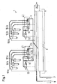
- Fig. 1 shows a schematic representation of an embodiment of a system according to the common rail principle for injecting liquid into a combustion chamber of an internal combustion engine.
- the system 1 for injecting liquid comprises a high-pressure accumulator 2, for example a so-called water rail, which is designed, for example, as a high pressure-resistant longitudinal line.
- the high-pressure accumulator 2 is supplied by a high-pressure pump, not shown, via a pressure line 7 with liquid, for example water at a pressure of about 400 bar.
- Two identically designed injection units are connected to the high-pressure accumulator 2 via a pressure line 3 in order to inject liquid into one cylinder each of an internal combustion engine, for example a large diesel engine.
- Each injection unit comprises three injection valves 10.1ac, 10.2 ac, preferably according to the present invention, which are described in more detail on the following pages, and a control valve 4.1, 4.2, for example a control valve according to the document EP-A-0 995 903, a throttle 6.1, 6.2 and a second control valve 5.1, 5.2, for example a solenoid valve.
- a control valve 4.1, 4.2 for example a control valve according to the document EP-A-0 995 903, a throttle 6.1, 6.2 and a second control valve 5.1, 5.2, for example a solenoid valve.
- the control valve 4.1, 4.2 shown in FIG. 1 corresponds to the control valve described in document EP-A-0 995 903.
- the control valve of Fig. 1 comprises a control piston 4.1a, which is arranged on the left in the drawing and a closing element 4.1c, which is arranged on the right and is connected via a shaft 4.1b with the control piston 4.1a.
- the second control valve 5.1 At rest, when no liquid is injected, the second control valve 5.1 is closed and the full pressure from the high-pressure accumulator 2 acts on both sides of the control piston 4.1a and on the closing element 4.1c.
- the diameter of the control piston 4.1a, 4.1b of the shank and the closing element 4.1c are coordinated so that the closing element is pressed into the closed position.
- the second control valve 5.1 is opened to the return line 8 and the pressure on the right side of the control piston 4.1a drops as a result of the throttle 6.1 until the pressure acting on the left side of the control piston shifts the control piston 4.1a as far as that the closing element 4.1c is opened.
- the closing piston 4.1a and / or the shaft 4.2b and / or a part of the shaft according to the present invention is formed.
- the piston according to the invention is explained in more detail in the context of the exemplary embodiment of an injection valve described below.
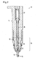
- Fig. 2 shows an embodiment of an injection valve according to the present invention.
- the injection valve 10 of the embodiment comprises a nozzle holder 11, a high-pressure piston-cylinder unit 15 and a nozzle head 13 with nozzle openings 14.
- the high-pressure piston-cylinder unit 15 comprises a nozzle body 12 with a cylinder bore and a piston 20 which is arranged movably in the cylinder bore is.
- the injection valve 1 comprises a valve needle 21, which is formed in the embodiment of the piston 20, a arranged in the extension of the valve needle 21 needle seat on which the valve needle sealingly rests with the injection valve closed, arranged in the extension of the piston 20 plunger 16 and a Compression spring 17 whose spring force is transmitted via the plunger 16 to the piston.
- the with the Piston-connected valve needle 21 is thus, as long as the voltage applied to the injection valve fluid pressure is low, pressed against the needle seat, so that the injection valve is self-closing.
- Fig. 3 shows the valve body 12 and the piston 20 of the injector shown in Fig. 2 in detail.
- the valve body comprises in the exemplary embodiment an opening 18 for supplying the injection fluid.
- the opening 18 is connected to a cavity surrounding the valve needle 21 in the valve body 12, so that the pressure of the injection fluid acts both on the piston 20 and on the closing point, i. the valve needle 21 and the needle seat.
- the reciprocating in the cylinder bore 19 and piston 20 is subject during operation, in particular during the injection of water, a disturbing Abnützung.
- a lateral surface of the piston 20 and / or the cylinder bore 19 are provided with grooves 22, and the lateral surface and / or the cylinder bore 19 additionally have abrasion-resistant protective layers.
- the groove width can be 50-1000 ⁇ m, advantageously 120-500 ⁇ m.
- the grooves 22 are expediently formed transversely to the longitudinal direction of the piston 20. A helical arrangement is also possible.
- the groove spacing is in the embodiment 100 - 2000 microns. In an advantageous embodiment, the groove spacing is not chosen constant, but adapted, for example, to the pressure prevailing on the piston. For example, on the high-pressure side of the piston, there is a larger groove spacing than on the low-pressure side.
- the abrasion-resistant protective layer is inert and / or resistant to water.
- the abrasion-resistant protective layer consists of Diamond Like Carbon (DLC) or of one or more ceramic materials, in particular Al 2 O 3 , SiO 2 , TiN, Si 3 N 4 , SiC, TiC, WC, or hard chrome or the protective layer contains one of these substances.
- DLC Diamond Like Carbon
- the piston 20 and the cylinder bore 19 at those points where the piston and the cylinder bore touch, depending on a different material structure. Due to the different material structure, the sticking of the piston 29 to the cylinder bore 19 can be reduced.
- the materials of which the piston 20 and the adjacent structural parts, such as the cylinder bore 19, so that the difference of the electrochemical potentials of the materials is as small as possible, for example less than 1 V, advantageously smaller than 0.2 V.
- the thus designed piston and thus designed high-pressure piston-cylinder unit 15 have compared to the prior art, a much lower wear, especially when injecting water.
Landscapes
- Engineering & Computer Science (AREA)
- Chemical & Material Sciences (AREA)
- Combustion & Propulsion (AREA)
- Mechanical Engineering (AREA)
- General Engineering & Computer Science (AREA)
- Fuel-Injection Apparatus (AREA)
- Details Of Reciprocating Pumps (AREA)
- Chemical Vapour Deposition (AREA)
Description
- Die Erfindung betrifft einen Kolben zur Verwendung in einer Hochdruck-Kolben-Zylindereinheit eines Steuer- oder Einspritzventils für Brennkraftmaschinen gemäss Oberbegriff von Anspruch 1, eine Hochdruck-Kolben-Zylindereinheit zur Verwendung in einem Steuer- oder Einspritzventil für Brennkraftmaschinen gemäss Oberbegriff von Anspruch 2, ein Steuer- oder Einspritzventil zum Einspritzen von Flüssigkeit in einen Brennraum einer Brennkraftmaschine mit einem derartigen Kolben oder mit einer derartigen Hochdruck-Kolben-Zylindereinheit, und die Verwendung eines derartigen Kolbens, einer derartigen Hochdruck-Kolben-Zylindereinheit oder eines derartigen Steuer- oder Einspritzventils.
- In Brennkraftmaschinen, insbesondere Brennkraftmaschinen der Dieselbauart und speziell in Grossdieselmotoren wird häufig neben Brennstoff auch Wasser in den oder die Brennräume eingespritzt. Das Einspritzen von Wasser hat den Zweck, den Gehalt an umweltbelastenden Stickoxiden (NOx) in den Abgasen der Brennkraftmaschine zu senken. Neben dem direkten Einspritzen von Wasser in die Brennräume kann auch eine Wasser-Brennstoffemulsion hergestellt werden, die dann in die Brennräume eingespritzt wird. Bei grösseren Brennräumen ist es üblich, für Brennstoff und Wasser mehrere Einspritzventile und Einspritzdüsen pro Zylinder vorzusehen, um eine bessere Verteilung des Brennstoffs beziehungsweise Wassers im Brennraum und eine gezielte Senkung der Spitzentemperaturen zu erreichen.
- In den letzten Jahren ist man dazu übergegangen, den Brennstoff und/oder das Wasser nach dem Common Rail-Prinzip einzuspritzen. Bei diesem Verfahren wird der Brennstoff und/oder das Wasser von einer beziehungsweise je einer Hochdruckpumpe verdichtet und einem beziehungsweise je einem Hochdruckspeicher zugeführt. Der oder die Hochdruckspeicher sind wahlweise direkt oder über Steuerventile mit Einspritzventilen verbunden, die mit Einspritzdüsen versehen sind, um den Brennstoff beziehungsweise das Wasser abhängig von der Zündreihenfolge in die Brennräume einzuspritzen. Der Druck im Hochdruckspeicher entspricht im Wesentlichen dem Einspritzdruck.
- Es hat sich gezeigt, dass die Kolben von Einspritz- und Steuerventilen für Brennkraftmaschinen einer verstärkten Abnützung unterliegen. Dies gilt insbesondere für Einspritzsysteme nach dem Common Rail-Prinzip, da in diesem Fall der hohe Druck unvermindert während des gesamten Kolbenhubs wirksam ist. Ein Grund für die vorzeitige Abnützung liegt z.B. in der ungenügenden Zentrierung der Kolben in den Zylinderbohrungen, die zu einem "Festfressen" der Kolben führen kann.
- Die Druckschrift EP-A-1 066 466 offenbart eine Hochdruck-Kolbenzylindereinheit einer Einspritzpumpe oder eines Einspritzventils zum Einspritzen von Brennstoff in Brennkraftmaschinen, in welcher der Kolben an der Mantelfläche in Abständen von 0.05 bis 1 mm mit Rillen versehen ist. Dank der Rillen wird der Druck gleichmässiger über den Umfang des Kolbens verteilt, womit die Zentrierung des Kolbens verbessert und die Abnützung reduziert wird. Weiter wird durch den in den Rillen vorhandenen Brennstoff eine Schmierwirkung erzielt. Die in EP-A-1 066 466 gemachten Angaben gelten für das Einspritzen von Dieselöl.
- Die Druckschrift EP-A-1 156 209 offenbart Ventilsteuerkolben von Injektoren für Common-Rail-Einspritzsysteme mit bewegbaren und stationären Führungsflächen. Die Leckage im Dichtspalt zwischen den Führungsflächen wird dadurch minimiert, dass dieselben eine Strukturierung aufweisen.
- Beim Einspritzen von Wasser in den Brennraum einer Brennkraftmaschine treten dagegen immer noch grössere Abnützungserscheinungen an Kolben und Zylinderbohrungen der Einspritz- und Steuerventile auf, selbst wenn die Kolben an der Mantelfläche mit Rillen versehen sind, weil durch Reibung und Adhäsion die inerte Passivschicht, welche zum Schutz gegen Korrosion notwendig ist, verletzt wird und dadurch die betroffenen Teile durch Korrosion zerstört werden. Die aus dem Stand der Technik bekannten Einspritz- und Steuerventile weisen deshalb beim Einspritzen von Wasser einen erhöhten Verschleiss auf und erreichen nicht die gewünschten Standzeiten in der Grössenordnung der Standzeiten der für die Brennstoffeinspritzung eingesetzten Einspritz- und Steuerventile.
- Aufgabe der Erfindung ist es, einen Kolben zur Verwendung in einer Hochdruck-Kolben-Zylindereinheit eines Steuer- oder Einspritzventils für Brennkraftmaschinen, eine Hochdruck-Kolben-Zylindereinheit zur Verwendung in einem Steuer- oder Einspritzventil für Brennkraftmaschinen mit einem derartigen Kolben, und ein Steuer- oder Einspritzventil zum Einspritzen von Flüssigkeit, insbesondere von Wasser, in einen Brennraum einer Brennkraftmaschine zur Verfügung zu stellen, die gegenüber dem Stand der Technik eine verminderte Abnützung aufweisen und deren Standzeiten beim Einspritzen von Wasser in derselben Grössenordnung liegen wie die Standzeiten, die mit Einspritz- und Steuerventile aus dem Stand der Technik beim Einspritzen von Brennstoff erreicht werden. Eine weitere Aufgabe der Erfindung besteht darin, ein Verfahren zur Verfügung zu stellen, das die Verwendung eines derartigen Kolbens, einer derartigen Hochdruck-Kolben-Zylindereinheit oder eines derartigen Steuer- oder Einspritzventils zum Gegenstand hat.
- Diese Aufgabe wird erfindungsgemäss durch den in Anspruch 1 definierten Kolben, die in Anspruch 2 definierte Hochdruck-Kolben-Zylindereinheit und das in Anspruch 7 definierte Einspritz- oder Steuerventil gelöst, sowie durch das im Verwendungsanspruch 9 definierte Verfahren.
- Die Erfindung umfasst in einer ersten Ausführungsform einen Kolben zur Verwendung in einer Hochdruck-Kolben-Zylindereinheit eines Steuer- oder Einspritzventils für Brennkraftmaschinen, welcher Kolben eine Mantelfläche umfasst, die sowohl mit Rillen als auch mit einer abriebfesten, vorzugsweise adhäsionsverhindernden Schutzschicht versehen ist.
- Die Erfindung umfasst in einer zweiten Ausführungsform eine Hochdruck-Kolben-Zylindereinheit zur Verwendung in einem Steuer- oder Einspritzventil für Brennkraftmaschinen, welche Hochdruck-Kolben-Zylindereinheit einen Kolben (20) und eine Zylinderbohrung (19) umfasst, in welcher Zylinderbohrung der Kolben (20) bewegbar angeordnet ist, wobei eine Mantelfläche des Kolbens (20) und/oder die Zylinderbohrung (19) mit Rillen (22) versehen sind, und wobei die Mantelfläche des Kolbens (20) und/oder die Zylinderbohrung (19) eine abriebfeste Schutzschicht aufweisen.
- Vorzugsweise ist die Schutzschicht so ausgebildet, dass sie inert ist und/oder beständig gegen Wasser, und/oder dass sie aus Diamond Like Carbon (DLC) oder aus einem oder mehreren keramischen Werkstoffen, insbesondere Al2O3, SiO2, TiN, Si3N4, SiC, TiC, WC, oder aus Hartchrom besteht oder einen dieser Stoffe enthält.
- Vorzugsweise beträgt die Rillenbreite 120 - 500 µm und/oder der Rillenabstand 100 - 2000 µm. Vorzugsweise ist der Rillenabstand auf der Hochdruckseite des Kolbens grösser ist als auf der Niederdruckseite.
- Vorzugsweise ist der Kolben mit einer Ventilnadel gekoppelt, und/oder der Kolben umfasst eine Ventilnadel und/oder der Kolben und die Ventilnadel sind einstückig ausgebildet. In einer Ausführungsvariante sind der Kolben und die Ventilnadel mehrstückig ausgebildet. In einer weiteren Ausführungsvariante sind der Kolben und die Ventilnadel mittels Reibungs-, Laser- oder Elektronstrahlschweissen miteinander verbunden.
- Vorzugsweise weisen der Kolben und die Zylinderbohrung an denjenigen Stellen, an denen sich der Kolben und die Zylinderbohrung berühren, je eine unterschiedliche Materialstruktur auf. Vorzugsweise bestehen der Kolben und die Zylinderbohrung an diesen Stellen aus Materialien, die im Wesentlichen dasselbe elektrochemische Potential aufweisen.
- Die Erfindung umfasst in einer dritten Ausführungsform ein Steuer- oder Einspritzventil zum Einspritzen von Flüssigkeit, insbesondere zum Einspritzen von Wasser, in einen Brennraum einer Brennkraftmaschine, welches Steuer- oder Einspritzventil einen oben beschriebenen Kolben oder eine oben beschriebene Hochdruck-Kolben-Zylindereinheit umfasst. Vorzugsweise dient das Steuer- oder Einspritzventil zum Einspritzen von Flüssigkeit nach dem Common Rail-Prinzip.
- Weiter umfasst die Erfindung eine Brennkraftmaschine mit mindestens einem Steuer- oder Einspritzventil gemäss der oben stehenden Beschreibung.
- Weiter umfasst die Erfindung auch die Verwendung des oben beschriebenen Kolbens oder der oben beschriebenen Hochdruck-Kolben-Zylindereinheit oder des oben beschriebenen Steuer- oder Einspritzventils zum Einspritzen von Wasser in einen Brennraum einer Brennkraftmaschine, insbesondere in einen Brennraum eines Grossdieselmotors. Vorzugsweise wird Wasser eingespritzt, um den NOx-Gehaltes der von der Brennkraftmaschine abgegebenen Abgase zu reduzieren.
- Der erfindungsgemässe Kolben, die Hochdruck-Kolben-Zylindereinheit mit einem derartigen Kolben und das Steuer- oder Einspritzventil zum Einspritzen von Flüssigkeit in einen Brennraum einer Brennkraftmaschine mit einem derartigen Kolben oder mit einer derartigen Hochdruck-Kolben-Zylindereinheit haben den Vorteil, dass sie gegenüber dem Stand der Technik eine wesentlich geringere Abnützung aufweisen. Dies gilt insbesondere auch für das Einspritzen von Wasser in einen Brennraum einer Brennkraftmaschine. Im Unterschied zu Dieselöl besitzt Wasser nur ungenügende Schmiereigenschaften, so dass die aus dem Stand der Technik bekannte Schmierwirkung der Rillen bei Wasser entfällt. Damit unterliegen die herkömmlichen Steuer- oder Einspritzventile beim Einspritzen von Wasser einer ungleich stärkeren Abnützung. Steuer- oder Einspritzventile werden meist aus Einsatzstahl gefertigt. Leider übt das üblicherweise verwendete Leitungswasser bei höheren Betriebstemperaturen eine korrosive Wirkung auf Einsatzstähle aus, wodurch die Abnützung zusätzlich verstärkt wird. Der erfindungsgemässe Kolben und die erfindungsgemässe Hochdruck-Kolben-Zylindereinheit, die sowohl mit Rillen als auch mit einer abriebfesten Schutzschicht versehen sind, weisen demgegenüber auch beim Einspritzen von Wasser eine vergleichsweise geringe Abnützung auf. Die Standzeiten des erfindungsgemässen Kolbens, der erfindungsgemässen Hochdruck-Kolben-Zylindereinheit und des Steuer- oder Einspritzventils mit einem derartigen Kolben oder mit einer derartigen Hochdruck-Kolben-Zylindereinheit beim Einspritzen von Wasser sind vergleichbar mit den Standzeiten der herkömmlichen Steuer- oder Einspritzventile beim Einspritzen von Brennstoff. Besonders vorteilhaft ist die in einer bevorzugten Ausführungsvariante beschriebene Verwendung einer inerten Schutzschicht und/oder einer Schutzschicht, die gegen Wasser beständig ist. Ebenfalls vorteilhaft ist die in einer weiteren bevorzugten Ausführungsvariante angegebene Rillenbreite von 120 - 500 µm und der angegebene Rillenabstand von 100 - 2000 µm.
- Weitere vorteilhafte Ausführungsformen gehen aus den abhängigen Ansprüchen und der Zeichnung hervor.
- Im Folgenden wird die Erfindung an Hand der Ausführungsbeispiele und an Hand der Zeichnung näher erläutert. Es zeigen:
- Fig. 1
- eine schematische Darstellung eines Ausführungsbeispiel eines Systems nach dem Common Rail-Prinzip zum Einspritzen von Flüssigkeit in einen Brennraum einer Brennkraftmaschine,
- Fig. 2
- ein Ausführungsbeispiel eines Einspritzventils gemäss der vorliegenden Erfindung im Schnitt, und
- Fig. 3
- Detailansicht des Ventilkörpers und Kolbens des in Fig. 2 gezeigten Einspritzventils.
- Fig. 1 zeigt eine schematische Darstellung eines Ausführungsbeispiel eines Systems nach dem Common Rail-Prinzip zum Einspritzen von Flüssigkeit in einen Brennraum einer Brennkraftmaschine. Das System 1 zum Einspritzen von Flüssigkeit umfasst einen Hochdruckspeicher 2, z.B. eine sogenannte Water Rail, der beispielsweise als hochdruckfeste Längsleitung ausgebildet ist. Der Hochdruckspeicher 2 wird von einer nicht gezeigten Hochdruckpumpe über eine Druckleitung 7 mit Flüssigkeit, beispielsweise Wasser mit einem Druck von etwa 400 bar, versorgt. Über eine Druckleitung 3 sind zwei identisch ausgelegte Einspritzeinheiten am Hochdruckspeicher 2 angeschlossen, um Flüssigkeit in je einen Zylinder einer Brennkraftmaschine, beispielsweise eines Grossdieselmotors, einzuspritzen. Jede Einspritzeinheit umfasst drei Einspritzventile 10.1a-c, 10.2 a-c, vorzugsweise gemäss der vorliegenden Erfindung, welche auf den nächsten Seiten näher beschrieben sind, sowie ein Steuerventil 4.1, 4.2, z.B. ein Steuerventil gemäss Dokument EP-A- 0 995 903, eine Drossel 6.1, 6.2 und ein zweites Steuerventil 5.1, 5.2, beispielsweise ein Magnetventil.
- Das in Fig. 1 gezeigte Steuerventil 4.1, 4.2 entspricht dem in Dokument EP-A-0 995 903 beschriebenen Steuerventil. Das Steuerventil von Fig. 1 umfasst einen Steuerkolben 4.1a, der auf der Zeichnung links angeordnet ist und ein Schliesselement 4.1c, das rechts angeordnet ist und über einen Schaft 4.1b mit dem Steuerkolben 4.1a verbunden ist. Im Ruhezustand, wenn keine Flüssigkeit eingespritzt wird, ist das zweite Steuerventil 5.1 geschlossen und der volle Druck aus dem Hochdruckspeicher 2 wirkt auf beide Seiten des Steuerkolbens 4.1a und auf das Schliesselement 4.1c. Dabei sind die Durchmesser des Steuerkolbens 4.1a, des Schaftes 4.1b und des Schliesselementes 4.1c so aufeinander abgestimmt, dass das Schliesselement in die Schliessstellung gedrückt wird. Zum Einspritzen von Flüssigkeit wird das zweite Steuerventil 5.1 zur Rücklaufleitung 8 hin geöffnet und der Druck auf der rechten Seite des Steuerkolbens 4.1a fällt in Folge der Drossel 6.1 ab, bis der auf der linken Seite des Steuerkolbens wirkende Druck den Steuerkolben 4.1a soweit verschiebt, dass das Schliesselement 4.1c geöffnet wird. Vorteilhafterweise ist der Schliesskolben 4.1a und/oder der Schaft 4.2b und/oder ein Teil des Schaftes gemäss der vorliegenden Erfindung ausgebildet. Der erfindungsgemässe Kolben wird im Rahmen des nachstehend beschriebenen Ausführungsbeispiels eines Einspritzventils näher erläutert.
- Fig. 2 zeigt ein Ausführungsbeispiel eines Einspritzventils gemäss der vorliegenden Erfindung. Das Einspritzventil 10 des Ausführungsbeispiels umfasst einen Düsenhalter 11, eine Hochdruck-Kolben-Zylindereinheit 15 und einen Düsenkopf 13 mit Düsenöffnungen 14. Die Hochdruck-Kolben-Zylindereinheit 15 umfasst einen Düsenkörper 12 mit einer Zylinderbohrung und einen Kolben 20, der in der Zylinderbohrung bewegbar angeordnet ist. Weiter umfasst das Einspritzventil 1 eine Ventilnadel 21, die im Ausführungsbeispiel am Kolben 20 ausgebildet ist, einen in der Verlängerung der Ventilnadel 21 angeordneten Nadelsitz, auf dem die Ventilnadel bei geschlossenem Einspritzventil dichtend aufliegt, einen in der Verlängerung des Kolbens 20 angeordneten Stössel 16 und eine Druckfeder 17, deren Federkraft über den Stössel 16 auf den Kolben übertragen wird. Die mit dem Kolben verbundene Ventilnadel 21 wird somit, solange der am Einspritzventil anliegende Flüssigkeitsdruck gering ist, gegen den Nadelsitz gedrückt, sodass das Einspritzventil selbstschliessend ist.
- Fig. 3 zeigt den Ventilkörper 12 und den Kolben 20 des in Fig. 2 gezeigten Einspritzventils im Detail. Der Ventilkörper umfasst im Ausführungsbeispiel eine Öffnung 18 zum Zuführen der Einspritzflüssigkeit. Die Öffnung 18 ist mit einem die Ventilnadel 21 umgebenden Hohlraum im Ventilkörper 12 verbunden, sodass der Druck der Einspritzflüssigkeit sowohl auf den Kolben 20 wirkt als auch auf die Schliessstelle, d.h. die Ventilnadel 21 und den Nadelsitz. Übersteigt die Kraft, die durch den Flüssigkeitsdruck auf den Kolben 20 ausgeübt wird, die Federkraft der Druckfeder 17, so verschiebt sich der Kolben 20 und die Ventilnadel 21 wird aus dem Nadelsitz gehoben und gibt den Weg zum Düsenkopf 13 frei für die Einspritzflüssigkeit. Sinkt im umgekehrten Fall die Kraft, die durch den Flüssigkeitsdruck auf den Kolben 20 ausgeübt wird, unter die Federkraft der Druckfeder 17, so wird der Kolben 20 durch die Federkraft zurückgeschoben, womit die Ventilnadel 21 gegen den Nadelsitz gedrückt wird und das Einspritzventil schliesst. Das Einspritzventil wird somit direkt durch den Druck der Einspritzflüssigkeit gesteuert.
- Der in der Zylinderbohrung 19 hin- und hergeschobene Kolben 20 unterliegt im Betrieb, insbesondere beim Einspritzen von Wasser, einer störenden Abnützung. Um die Abnützung zu reduzieren, sind eine Mantelfläche des Kolbens 20 und/oder die Zylinderbohrung 19 mit Rillen 22 versehen, und die Mantelfläche und/oder die Zylinderbohrung 19 weisen zusätzlich abriebfeste Schutzschichten auf. Die Rillenbreite kann 50 -1000 µm, vorteilhafterweise 120 - 500 µm betragen. Die Rillen 22 sind zweckmässigerweise quer zur Längsrichtung des Kolbens 20 ausgebildet. Eine schraubenlinienförmige Anordnung ist ebenfalls möglich. Der Rillenabstand beträgt im Ausführungsbeispiel 100 - 2000 µm. In einer vorteilhaften Ausführungsvariante wird der Rillenabstand nicht konstant gewählt, sondern z.B. an den am Kolben herrschenden Druck angepasst. So ergibt sich auf der Hochdruckseite des Kolbens beispielsweise ein grösserer Rillenabstand als auf der Niederdruckseite.
- In einer bevorzugten Ausführungsvariante ist die abriebfeste Schutzschicht inert und/oder beständig gegen Wasser. In einer weiteren bevorzugten Ausführungsvariante besteht die abriebfeste Schutzschicht aus Diamond Like Carbon (DLC) oder aus einem oder mehreren keramischen Werkstoffen, insbesondere Al2O3, SiO2, TiN, Si3N4, SiC, TiC, WC, oder aus Hartchrom oder die Schutzschicht enthält einen dieser Stoffe. Mit Vorteil weisen der Kolben 20 und die Zylinderbohrung 19 an denjenigen Stellen, an denen sich der Kolben und die Zylinderbohrung berühren, je eine unterschiedliche Materialstruktur auf. Durch die unterschiedliche Materialstruktur kann das Festkleben des Kolbens 29 an der Zylinderbohrung 19 reduziert werden. Weiter ist es vorteilhaft, die Materialien, aus denen der Kolben 20 und die benachbarten Konstruktionsteile, wie beispielsweise die Zylinderbohrung 19, bestehen, so zu wählen, dass die Differenz der elektrochemischen Potentiale der Materialien möglichst klein ist, beispielsweise kleiner als 1 V, vorteilhafterweise kleiner als 0.2 V. Der derart ausgelegte Kolben und die derart ausgelegte Hochdruck-Kolben-Zylindereinheit 15 weisen gegenüber dem Stand der Technik eine wesentlich geringere Abnützung auf, insbesondere beim Einspritzen von Wasser.
Claims (10)
- Kolben zur Verwendung in einer Hochdruck-Kolben-Zylindereinheit eines Steuer- oder Einspritzventils zum Einspritzen von Wasser in Brennkraftmaschinen, wobei eine Mantelfläche des Kolbens (20) sowohl mit Rillen (22) als auch mit einer abriebfesten Schutzschicht versehen ist, dadurch gekennzeichnet, dass die Schutzschicht beständig gegen Wasser ist, und dass die Schutzschicht aus Diamond Like Carbon (DLC) oder aus TiN, Si3N4, SiC, TiC, WC oder Hartchrom besteht oder einen dieser Stoffe enthält.
- Hochdruck-Kolben-Zylindereinheit zur Verwendung in einem Steuer- oder Einspritzventil zum Einspritzen von Wasser in Brennkraftmaschinen, welche Hochdruck-Kolben-Zylindereinheit (15) einen Kolben (20) und eine Zylinderbohrung (19) umfasst, in welcher Zylinderbohrung der Kolben (20) bewegbar angeordnet ist, wobei eine Mantelfläche des Kolbens (20) und/oder die Zylinderbohrung (19) mit Rillen (22) versehen sind, und dass die Mantelfläche des Kolbens (20) und/oder die Zylinderbohrung (19) eine abriebfeste Schutzschicht aufweisen, gekennzeichnet dadurch, dass die Schutzschicht beständig gegen Wasser ist, und dass die Schutzschicht aus Diamond Like Carbon (DLC) oder aus TiN, Si3N4, SiC, TiC, WC oder Hartchrom besteht oder einen dieser Stoffe enthält.
- Kolben nach Anspruch 1 oder Hochdruck-Kolben-Zylindereinheit nach Anspruch 2, wobei die Rillenbreite 120 - 500 µm und/oder der Rillenabstand 100 - 2000 µm beträgt.
- Kolben nach einem der Ansprüche 1 oder 3 oder Hochdruck-Kolben-Zylindereinheit nach einem der Ansprüche 2 oder 3, wobei der Rillenabstand auf der Hochdruckseite des Kolbens (20) grösser ist als auf der Niederdruckseite.
- Kolben nach einem der Ansprüche 1, 3 oder 4 oder Hochdruck-Kolben-Zylindereinheit nach einem der Ansprüche 2 bis 4, wobei der Kolben (20) mit einer Ventilnadel (21) gekoppelt ist oder wobei der Kolben (20) eine Ventilnadel (21) umfasst.
- Kolben nach einem der Ansprüche 1, 3, 4 oder 5 oder Hochdruck-Kolben-Zylindereinheit nach einem der Ansprüche 2 bis 5, wobei der Kolben und die Ventilnadel einstückig ausgebildet sind.
- Hochdruck-Kolben-Zylindereinheit nach einem der Ansprüche 2 bis 6, wobei der Kolben (20) und die Zylinderbohrung (19) an denjenigen Stellen, an denen sich der Kolben und die Zylinderbohrung berühren, je eine unterschiedliche Materialstruktur aufweisen und/oder aus Materialien bestehen, die im Wesentlichen dasselbe elektrochemische Potential aufweisen.
- Steuer- oder Einspritzventil zum Einspritzen von Wasser nach dem Common Rail-Prinzip in einen Brennraum einer Brennkraftmaschine, welches Steuer- oder Einspritzventil (4.1, 4.2, 10, 10.1a-c, 10.2a-c) einen Kolben (20) nach einem der Ansprüche 1, 3, 4, 5 oder 6 oder eine Hochdruck-Kolben-Zylindereinheit (15) nach einem der Ansprüche 2 bis 7 umfasst.
- Brennkraftmaschine umfassend ein Steuer- oder Einspritzventil (4.1, 4.2, 10, 10.1a-c, 10.2a-c) nach Anspruch 8.
- Verwendung eines Kolbens (20) nach einem der Ansprüche 1, 3, 4, 5 oder 6 oder einer Hochdruck-Kolben-Zylindereinheit (15) nach einem der Ansprüche 2 bis 7 oder eines Steuer- oder Einspritzventils (4.1, 4.2, 10, 10.1a-c, 10.2a-c) nach Anspruch 8 zum Einspritzen von Wasser in einen Brennraum einer Brennkraftmaschine, insbesondere in einen Brennraum eines Grossdieselmotors, insbesondere zur Reduktion des NOx-Gehaltes der von der Brennkraftmaschine abgegebenen Abgase.
Priority Applications (2)
| Application Number | Priority Date | Filing Date | Title |
|---|---|---|---|
| EP04405372A EP1498603B1 (de) | 2003-07-16 | 2004-06-17 | Kolben für eine Hochdruck-Kolben-Zylindereinheit eines Einspritzventils |
| PL04405372T PL1498603T3 (pl) | 2003-07-16 | 2004-06-17 | Tłok dla wysokociśnieniowej jednostki tłokowo-cylindrowej zaworu wtryskowego |
Applications Claiming Priority (3)
| Application Number | Priority Date | Filing Date | Title |
|---|---|---|---|
| EP03405543 | 2003-07-16 | ||
| EP03405543 | 2003-07-16 | ||
| EP04405372A EP1498603B1 (de) | 2003-07-16 | 2004-06-17 | Kolben für eine Hochdruck-Kolben-Zylindereinheit eines Einspritzventils |
Publications (2)
| Publication Number | Publication Date |
|---|---|
| EP1498603A1 EP1498603A1 (de) | 2005-01-19 |
| EP1498603B1 true EP1498603B1 (de) | 2006-09-27 |
Family
ID=34203264
Family Applications (1)
| Application Number | Title | Priority Date | Filing Date |
|---|---|---|---|
| EP04405372A Expired - Lifetime EP1498603B1 (de) | 2003-07-16 | 2004-06-17 | Kolben für eine Hochdruck-Kolben-Zylindereinheit eines Einspritzventils |
Country Status (8)
| Country | Link |
|---|---|
| EP (1) | EP1498603B1 (de) |
| JP (1) | JP4792209B2 (de) |
| KR (1) | KR101307563B1 (de) |
| CN (1) | CN100449140C (de) |
| AT (1) | ATE340927T1 (de) |
| DE (1) | DE502004001570D1 (de) |
| DK (1) | DK1498603T3 (de) |
| PL (1) | PL1498603T3 (de) |
Cited By (1)
| Publication number | Priority date | Publication date | Assignee | Title |
|---|---|---|---|---|
| DE102007050811A1 (de) * | 2007-10-24 | 2009-04-30 | Robert Bosch Gmbh | Verschleißschutzschicht sowie Verfahren zu ihrer Herstellung |
Families Citing this family (7)
| Publication number | Priority date | Publication date | Assignee | Title |
|---|---|---|---|---|
| ATE421039T1 (de) | 2004-02-23 | 2009-01-15 | Waertsilae Nsd Schweiz Ag | Brennstoffeinspritzdüse |
| RU2306449C1 (ru) * | 2005-12-22 | 2007-09-20 | Виктор Адольфович Герман | Распылитель форсунки |
| DE102006017449A1 (de) * | 2006-04-13 | 2007-10-18 | Robert Bosch Gmbh | Kraftstoffinjektor mit hoher Lebensdauer und Verschleißfestigkeit |
| RU2405962C1 (ru) * | 2009-03-20 | 2010-12-10 | Государственное образовательное учреждение высшего профессионального образования Московский автомобильно-дорожный институт (Государственный технический университет) | Система подачи альтернативных топлив в камеру сгорания дизеля |
| DE102015211705A1 (de) * | 2015-06-24 | 2016-12-29 | Robert Bosch Gmbh | Kraftstoffinjektor mit Steuerventil |
| KR101724968B1 (ko) | 2015-12-11 | 2017-04-07 | 현대자동차주식회사 | 무게중심이 편심된 이종재질 피스톤핀 및 그 제조방법 |
| WO2019108495A1 (en) * | 2017-11-30 | 2019-06-06 | Cummins Inc. | Electroless nickel coating on fuel injector needle |
Family Cites Families (9)
| Publication number | Priority date | Publication date | Assignee | Title |
|---|---|---|---|---|
| JP2769422B2 (ja) * | 1993-04-19 | 1998-06-25 | 日立金属株式会社 | 内燃機関の燃料噴射ノズルまたはニードル用高強度ステンレス鋼、内燃機関用燃料噴射ノズルおよびその製造方法 |
| JPH10131828A (ja) * | 1996-10-31 | 1998-05-19 | Mitsubishi Heavy Ind Ltd | 噴射弁装置 |
| DE19706661A1 (de) * | 1997-02-20 | 1998-08-27 | Bosch Gmbh Robert | Kraftstoffeinspritzventil für Brennkraftmaschinen |
| WO1999049209A1 (de) * | 1998-03-26 | 1999-09-30 | Mtu Motoren- Und Turbinen-Union Friedrichshafen Gmbh | Hochdruck-kolbenzylindereinheit |
| JP4445072B2 (ja) * | 1998-10-20 | 2010-04-07 | ヴェルトジィレ シュヴァイツ アクチェンゲゼルシャフト | ディーゼルエンジンのシリンダへの液体噴射装置及びディーゼルエンジン |
| DE10024854C2 (de) * | 2000-05-19 | 2002-11-28 | Siemens Ag | Ventilnadel und Ventilsteuerkolben von Injektoren |
| JP2002161817A (ja) * | 2000-11-24 | 2002-06-07 | Toyota Motor Corp | インジェクタ |
| DE10133166A1 (de) * | 2001-07-07 | 2003-01-16 | Bosch Gmbh Robert | Kraftstoffeinspritzventil für Brennkraftmaschinen |
| JP4607383B2 (ja) * | 2001-07-30 | 2011-01-05 | いすゞ自動車株式会社 | 燃料噴射インジェクタの製造方法及び燃料噴射ポンプの製造方法 |
-
2004
- 2004-06-10 KR KR1020040042598A patent/KR101307563B1/ko not_active Expired - Fee Related
- 2004-06-15 JP JP2004176957A patent/JP4792209B2/ja not_active Expired - Fee Related
- 2004-06-17 DE DE502004001570T patent/DE502004001570D1/de not_active Expired - Lifetime
- 2004-06-17 DK DK04405372T patent/DK1498603T3/da active
- 2004-06-17 EP EP04405372A patent/EP1498603B1/de not_active Expired - Lifetime
- 2004-06-17 PL PL04405372T patent/PL1498603T3/pl unknown
- 2004-06-17 AT AT04405372T patent/ATE340927T1/de not_active IP Right Cessation
- 2004-07-06 CN CNB2004100634728A patent/CN100449140C/zh not_active Expired - Fee Related
Cited By (1)
| Publication number | Priority date | Publication date | Assignee | Title |
|---|---|---|---|---|
| DE102007050811A1 (de) * | 2007-10-24 | 2009-04-30 | Robert Bosch Gmbh | Verschleißschutzschicht sowie Verfahren zu ihrer Herstellung |
Also Published As
| Publication number | Publication date |
|---|---|
| KR20050010481A (ko) | 2005-01-27 |
| PL1498603T3 (pl) | 2007-02-28 |
| JP2005036800A (ja) | 2005-02-10 |
| CN1576570A (zh) | 2005-02-09 |
| JP4792209B2 (ja) | 2011-10-12 |
| EP1498603A1 (de) | 2005-01-19 |
| CN100449140C (zh) | 2009-01-07 |
| ATE340927T1 (de) | 2006-10-15 |
| DK1498603T3 (da) | 2006-11-27 |
| KR101307563B1 (ko) | 2013-09-12 |
| DE502004001570D1 (de) | 2006-11-09 |
Similar Documents
| Publication | Publication Date | Title |
|---|---|---|
| EP0828936B1 (de) | Einspritzventil | |
| EP0960274B1 (de) | Kraftstoffeinspritzvorrichtung für brennkraftmaschinen | |
| AT500773B1 (de) | Einspritzdüse für brennkraftmaschinen | |
| DE69911670T2 (de) | Kraftstoffeinspritzventil | |
| DE19709794A1 (de) | Ventil zum Steuern von Flüssigkeiten | |
| DE19905462A1 (de) | Keramischer Plungerkolben für ein Hochdruckkraftstoffsystem eines Innenverbrennungsmotors | |
| DE112006003077T5 (de) | Brennstoffsystem mit variablem Einspritzdruck | |
| WO1995017594A1 (de) | Krafstoffeinspritzvorrichtung mit hochdruch-kraftstoffspeicher | |
| WO2001073287A1 (de) | Einspritzventil mit bypassdrossel | |
| DE19709170C2 (de) | Abdichtung für hin- und hergehende Maschinenteile, insbesondere Ventilschaftabdichtung | |
| EP1066466A1 (de) | Hochdruck-kolbenzylindereinheit | |
| DE19634933B4 (de) | Kraftstoffeinspritzventil für Brennkraftmaschinen | |
| DE102008010242A1 (de) | Hochdruckerzeuger für Einspritzanlagen von Brennkraftmaschinen | |
| EP1498603A1 (de) | Kolben für eine Hochdruck-Kolben-Zylindereinheit eines Einspritzventils | |
| EP1125047B1 (de) | Kraftstoffeinspritzeinrichtung | |
| EP1373715A1 (de) | Kraftstoffeinspritzventil für brennkraftmaschinen | |
| DE19946830A1 (de) | Ventil zum Steuern von Flüssigkeiten | |
| EP1402174A1 (de) | Kraftstoffeinspritzeinrichtung für eine brennkraftmaschine | |
| WO2005078273A1 (de) | Hochdruckpumpe, insbesondere für eine kraftstoffeinspritzeinrichtung einer brennkraftmaschine | |
| EP1483499B1 (de) | Einrichtung zur druckmodulierten formung des einspritzverlaufes | |
| DE102004054589B4 (de) | Steuerventil und Einspritzventil | |
| DE69513880T2 (de) | Kraftstoffdruckerzeugende Kolbenanordnung für eine druckgezündete Brennkraftmaschine | |
| WO2004057177A1 (de) | Kraftstoffeinspritzeinrichtung für eine brennkraftmaschine | |
| EP1325228B1 (de) | Einspritzventil mit einem pumpkolben | |
| DE3117018A1 (de) | Kraftstoffeinspritzduese |
Legal Events
| Date | Code | Title | Description |
|---|---|---|---|
| PUAI | Public reference made under article 153(3) epc to a published international application that has entered the european phase |
Free format text: ORIGINAL CODE: 0009012 |
|
| AK | Designated contracting states |
Kind code of ref document: A1 Designated state(s): AT BE BG CH CY CZ DE DK EE ES FI FR GB GR HU IE IT LI LU MC NL PL PT RO SE SI SK TR |
|
| AX | Request for extension of the european patent |
Extension state: AL HR LT LV MK |
|
| 17P | Request for examination filed |
Effective date: 20050705 |
|
| AKX | Designation fees paid |
Designated state(s): AT BE BG CH CY CZ DE DK EE ES FI FR GB GR HU IE IT LI LU MC NL PL PT RO SE SI SK TR |
|
| GRAP | Despatch of communication of intention to grant a patent |
Free format text: ORIGINAL CODE: EPIDOSNIGR1 |
|
| GRAS | Grant fee paid |
Free format text: ORIGINAL CODE: EPIDOSNIGR3 |
|
| GRAA | (expected) grant |
Free format text: ORIGINAL CODE: 0009210 |
|
| AK | Designated contracting states |
Kind code of ref document: B1 Designated state(s): AT BE BG CH CY CZ DE DK EE ES FI FR GB GR HU IE IT LI LU MC NL PL PT RO SE SI SK TR |
|
| PG25 | Lapsed in a contracting state [announced via postgrant information from national office to epo] |
Ref country code: IT Free format text: LAPSE BECAUSE OF FAILURE TO SUBMIT A TRANSLATION OF THE DESCRIPTION OR TO PAY THE FEE WITHIN THE PRESCRIBED TIME-LIMIT;WARNING: LAPSES OF ITALIAN PATENTS WITH EFFECTIVE DATE BEFORE 2007 MAY HAVE OCCURRED AT ANY TIME BEFORE 2007. THE CORRECT EFFECTIVE DATE MAY BE DIFFERENT FROM THE ONE RECORDED. Effective date: 20060927 Ref country code: IE Free format text: LAPSE BECAUSE OF FAILURE TO SUBMIT A TRANSLATION OF THE DESCRIPTION OR TO PAY THE FEE WITHIN THE PRESCRIBED TIME-LIMIT Effective date: 20060927 Ref country code: SK Free format text: LAPSE BECAUSE OF FAILURE TO SUBMIT A TRANSLATION OF THE DESCRIPTION OR TO PAY THE FEE WITHIN THE PRESCRIBED TIME-LIMIT Effective date: 20060927 Ref country code: SI Free format text: LAPSE BECAUSE OF FAILURE TO SUBMIT A TRANSLATION OF THE DESCRIPTION OR TO PAY THE FEE WITHIN THE PRESCRIBED TIME-LIMIT Effective date: 20060927 Ref country code: CZ Free format text: LAPSE BECAUSE OF FAILURE TO SUBMIT A TRANSLATION OF THE DESCRIPTION OR TO PAY THE FEE WITHIN THE PRESCRIBED TIME-LIMIT Effective date: 20060927 Ref country code: NL Free format text: LAPSE BECAUSE OF FAILURE TO SUBMIT A TRANSLATION OF THE DESCRIPTION OR TO PAY THE FEE WITHIN THE PRESCRIBED TIME-LIMIT Effective date: 20060927 Ref country code: RO Free format text: LAPSE BECAUSE OF FAILURE TO SUBMIT A TRANSLATION OF THE DESCRIPTION OR TO PAY THE FEE WITHIN THE PRESCRIBED TIME-LIMIT Effective date: 20060927 |
|
| REG | Reference to a national code |
Ref country code: GB Ref legal event code: FG4D Free format text: NOT ENGLISH |
|
| REG | Reference to a national code |
Ref country code: CH Ref legal event code: EP Ref country code: CH Ref legal event code: NV Representative=s name: SULZER MANAGEMENT AG PATENTABTEILUNG/0067 |
|
| REG | Reference to a national code |
Ref country code: IE Ref legal event code: FG4D Free format text: LANGUAGE OF EP DOCUMENT: GERMAN |
|
| REF | Corresponds to: |
Ref document number: 502004001570 Country of ref document: DE Date of ref document: 20061109 Kind code of ref document: P |
|
| REG | Reference to a national code |
Ref country code: DK Ref legal event code: T3 |
|
| PG25 | Lapsed in a contracting state [announced via postgrant information from national office to epo] |
Ref country code: SE Free format text: LAPSE BECAUSE OF FAILURE TO SUBMIT A TRANSLATION OF THE DESCRIPTION OR TO PAY THE FEE WITHIN THE PRESCRIBED TIME-LIMIT Effective date: 20061227 Ref country code: BG Free format text: LAPSE BECAUSE OF FAILURE TO SUBMIT A TRANSLATION OF THE DESCRIPTION OR TO PAY THE FEE WITHIN THE PRESCRIBED TIME-LIMIT Effective date: 20061227 |
|
| PG25 | Lapsed in a contracting state [announced via postgrant information from national office to epo] |
Ref country code: ES Free format text: LAPSE BECAUSE OF FAILURE TO SUBMIT A TRANSLATION OF THE DESCRIPTION OR TO PAY THE FEE WITHIN THE PRESCRIBED TIME-LIMIT Effective date: 20070107 |
|
| REG | Reference to a national code |
Ref country code: PL Ref legal event code: T3 |
|
| NLV1 | Nl: lapsed or annulled due to failure to fulfill the requirements of art. 29p and 29m of the patents act | ||
| PG25 | Lapsed in a contracting state [announced via postgrant information from national office to epo] |
Ref country code: PT Free format text: LAPSE BECAUSE OF FAILURE TO SUBMIT A TRANSLATION OF THE DESCRIPTION OR TO PAY THE FEE WITHIN THE PRESCRIBED TIME-LIMIT Effective date: 20070313 |
|
| ET | Fr: translation filed | ||
| REG | Reference to a national code |
Ref country code: IE Ref legal event code: FD4D |
|
| GBV | Gb: ep patent (uk) treated as always having been void in accordance with gb section 77(7)/1977 [no translation filed] |
Effective date: 20060927 |
|
| PLBE | No opposition filed within time limit |
Free format text: ORIGINAL CODE: 0009261 |
|
| STAA | Information on the status of an ep patent application or granted ep patent |
Free format text: STATUS: NO OPPOSITION FILED WITHIN TIME LIMIT |
|
| 26N | No opposition filed |
Effective date: 20070628 |
|
| PG25 | Lapsed in a contracting state [announced via postgrant information from national office to epo] |
Ref country code: GB Free format text: LAPSE BECAUSE OF FAILURE TO SUBMIT A TRANSLATION OF THE DESCRIPTION OR TO PAY THE FEE WITHIN THE PRESCRIBED TIME-LIMIT Effective date: 20060927 |
|
| BERE | Be: lapsed |
Owner name: WARTSILA SCHWEIZ A.G. Effective date: 20070630 |
|
| PG25 | Lapsed in a contracting state [announced via postgrant information from national office to epo] |
Ref country code: MC Free format text: LAPSE BECAUSE OF NON-PAYMENT OF DUE FEES Effective date: 20070630 |
|
| PG25 | Lapsed in a contracting state [announced via postgrant information from national office to epo] |
Ref country code: BE Free format text: LAPSE BECAUSE OF NON-PAYMENT OF DUE FEES Effective date: 20070630 |
|
| PG25 | Lapsed in a contracting state [announced via postgrant information from national office to epo] |
Ref country code: GR Free format text: LAPSE BECAUSE OF FAILURE TO SUBMIT A TRANSLATION OF THE DESCRIPTION OR TO PAY THE FEE WITHIN THE PRESCRIBED TIME-LIMIT Effective date: 20061228 |
|
| PG25 | Lapsed in a contracting state [announced via postgrant information from national office to epo] |
Ref country code: EE Free format text: LAPSE BECAUSE OF FAILURE TO SUBMIT A TRANSLATION OF THE DESCRIPTION OR TO PAY THE FEE WITHIN THE PRESCRIBED TIME-LIMIT Effective date: 20060927 |
|
| PG25 | Lapsed in a contracting state [announced via postgrant information from national office to epo] |
Ref country code: AT Free format text: LAPSE BECAUSE OF NON-PAYMENT OF DUE FEES Effective date: 20070617 |
|
| PGRI | Patent reinstated in contracting state [announced from national office to epo] |
Ref country code: IT Effective date: 20080801 |
|
| PG25 | Lapsed in a contracting state [announced via postgrant information from national office to epo] |
Ref country code: CY Free format text: LAPSE BECAUSE OF FAILURE TO SUBMIT A TRANSLATION OF THE DESCRIPTION OR TO PAY THE FEE WITHIN THE PRESCRIBED TIME-LIMIT Effective date: 20060927 Ref country code: LU Free format text: LAPSE BECAUSE OF NON-PAYMENT OF DUE FEES Effective date: 20070617 |
|
| PG25 | Lapsed in a contracting state [announced via postgrant information from national office to epo] |
Ref country code: TR Free format text: LAPSE BECAUSE OF FAILURE TO SUBMIT A TRANSLATION OF THE DESCRIPTION OR TO PAY THE FEE WITHIN THE PRESCRIBED TIME-LIMIT Effective date: 20060927 Ref country code: HU Free format text: LAPSE BECAUSE OF FAILURE TO SUBMIT A TRANSLATION OF THE DESCRIPTION OR TO PAY THE FEE WITHIN THE PRESCRIBED TIME-LIMIT Effective date: 20070328 |
|
| PGFP | Annual fee paid to national office [announced via postgrant information from national office to epo] |
Ref country code: FI Payment date: 20100615 Year of fee payment: 7 Ref country code: FR Payment date: 20100706 Year of fee payment: 7 |
|
| PGFP | Annual fee paid to national office [announced via postgrant information from national office to epo] |
Ref country code: PL Payment date: 20100521 Year of fee payment: 7 |
|
| PG25 | Lapsed in a contracting state [announced via postgrant information from national office to epo] |
Ref country code: FI Free format text: LAPSE BECAUSE OF NON-PAYMENT OF DUE FEES Effective date: 20110617 |
|
| REG | Reference to a national code |
Ref country code: FR Ref legal event code: ST Effective date: 20120229 |
|
| PG25 | Lapsed in a contracting state [announced via postgrant information from national office to epo] |
Ref country code: FR Free format text: LAPSE BECAUSE OF NON-PAYMENT OF DUE FEES Effective date: 20110630 |
|
| PG25 | Lapsed in a contracting state [announced via postgrant information from national office to epo] |
Ref country code: PL Free format text: LAPSE BECAUSE OF NON-PAYMENT OF DUE FEES Effective date: 20110617 |
|
| REG | Reference to a national code |
Ref country code: PL Ref legal event code: LAPE |
|
| REG | Reference to a national code |
Ref country code: CH Ref legal event code: NV Representative=s name: INTELLECTUAL PROPERTY SERVICES GMBH, CH |
|
| REG | Reference to a national code |
Ref country code: CH Ref legal event code: PCAR Free format text: NEW ADDRESS: LANGFELDSTRASSE 88, 8500 FRAUENFELD (CH) |
|
| PGFP | Annual fee paid to national office [announced via postgrant information from national office to epo] |
Ref country code: DE Payment date: 20190619 Year of fee payment: 16 Ref country code: DK Payment date: 20190621 Year of fee payment: 16 Ref country code: IT Payment date: 20190624 Year of fee payment: 16 |
|
| PGFP | Annual fee paid to national office [announced via postgrant information from national office to epo] |
Ref country code: CH Payment date: 20190619 Year of fee payment: 16 |
|
| REG | Reference to a national code |
Ref country code: DE Ref legal event code: R119 Ref document number: 502004001570 Country of ref document: DE |
|
| REG | Reference to a national code |
Ref country code: DK Ref legal event code: EBP Effective date: 20200630 |
|
| REG | Reference to a national code |
Ref country code: CH Ref legal event code: PL |
|
| PG25 | Lapsed in a contracting state [announced via postgrant information from national office to epo] |
Ref country code: LI Free format text: LAPSE BECAUSE OF NON-PAYMENT OF DUE FEES Effective date: 20200630 Ref country code: CH Free format text: LAPSE BECAUSE OF NON-PAYMENT OF DUE FEES Effective date: 20200630 |
|
| PG25 | Lapsed in a contracting state [announced via postgrant information from national office to epo] |
Ref country code: DE Free format text: LAPSE BECAUSE OF NON-PAYMENT OF DUE FEES Effective date: 20210101 |
|
| PG25 | Lapsed in a contracting state [announced via postgrant information from national office to epo] |
Ref country code: DK Free format text: LAPSE BECAUSE OF NON-PAYMENT OF DUE FEES Effective date: 20200630 |
|
| PG25 | Lapsed in a contracting state [announced via postgrant information from national office to epo] |
Ref country code: IT Free format text: LAPSE BECAUSE OF FAILURE TO SUBMIT A TRANSLATION OF THE DESCRIPTION OR TO PAY THE FEE WITHIN THE PRESCRIBED TIME-LIMIT Effective date: 20200617 |