EP1498229A2 - Verfahren zum Stanzen von einer zumindest einseitig klebend ausgerüsteten Bahn, die sich auf einem Abdeckmaterial befindet, in einzelne Stanzlinge - Google Patents
Verfahren zum Stanzen von einer zumindest einseitig klebend ausgerüsteten Bahn, die sich auf einem Abdeckmaterial befindet, in einzelne Stanzlinge Download PDFInfo
- Publication number
- EP1498229A2 EP1498229A2 EP04013991A EP04013991A EP1498229A2 EP 1498229 A2 EP1498229 A2 EP 1498229A2 EP 04013991 A EP04013991 A EP 04013991A EP 04013991 A EP04013991 A EP 04013991A EP 1498229 A2 EP1498229 A2 EP 1498229A2
- Authority
- EP
- European Patent Office
- Prior art keywords
- adhesive
- punching
- web
- diecuts
- der
- Prior art date
- Legal status (The legal status is an assumption and is not a legal conclusion. Google has not performed a legal analysis and makes no representation as to the accuracy of the status listed.)
- Granted
Links
Images




Classifications
-
- B—PERFORMING OPERATIONS; TRANSPORTING
- B26—HAND CUTTING TOOLS; CUTTING; SEVERING
- B26D—CUTTING; DETAILS COMMON TO MACHINES FOR PERFORATING, PUNCHING, CUTTING-OUT, STAMPING-OUT OR SEVERING
- B26D3/00—Cutting work characterised by the nature of the cut made; Apparatus therefor
- B26D3/10—Making cuts of other than simple rectilinear form
-
- B—PERFORMING OPERATIONS; TRANSPORTING
- B26—HAND CUTTING TOOLS; CUTTING; SEVERING
- B26D—CUTTING; DETAILS COMMON TO MACHINES FOR PERFORATING, PUNCHING, CUTTING-OUT, STAMPING-OUT OR SEVERING
- B26D1/00—Cutting through work characterised by the nature or movement of the cutting member or particular materials not otherwise provided for; Apparatus or machines therefor; Cutting members therefor
-
- B—PERFORMING OPERATIONS; TRANSPORTING
- B26—HAND CUTTING TOOLS; CUTTING; SEVERING
- B26D—CUTTING; DETAILS COMMON TO MACHINES FOR PERFORATING, PUNCHING, CUTTING-OUT, STAMPING-OUT OR SEVERING
- B26D3/00—Cutting work characterised by the nature of the cut made; Apparatus therefor
- B26D3/08—Making a superficial cut in the surface of the work without removal of material, e.g. scoring, incising
- B26D3/085—On sheet material
-
- B—PERFORMING OPERATIONS; TRANSPORTING
- B65—CONVEYING; PACKING; STORING; HANDLING THIN OR FILAMENTARY MATERIAL
- B65H—HANDLING THIN OR FILAMENTARY MATERIAL, e.g. SHEETS, WEBS, CABLES
- B65H35/00—Delivering articles from cutting or line-perforating machines; Article or web delivery apparatus incorporating cutting or line-perforating devices, e.g. adhesive tape dispensers
- B65H35/04—Delivering articles from cutting or line-perforating machines; Article or web delivery apparatus incorporating cutting or line-perforating devices, e.g. adhesive tape dispensers from or with transverse cutters or perforators
- B65H35/06—Delivering articles from cutting or line-perforating machines; Article or web delivery apparatus incorporating cutting or line-perforating devices, e.g. adhesive tape dispensers from or with transverse cutters or perforators from or with blade, e.g. shear-blade, cutters or perforators
-
- B—PERFORMING OPERATIONS; TRANSPORTING
- B26—HAND CUTTING TOOLS; CUTTING; SEVERING
- B26F—PERFORATING; PUNCHING; CUTTING-OUT; STAMPING-OUT; SEVERING BY MEANS OTHER THAN CUTTING
- B26F1/00—Perforating; Punching; Cutting-out; Stamping-out; Apparatus therefor
- B26F1/38—Cutting-out; Stamping-out
- B26F1/40—Cutting-out; Stamping-out using a press, e.g. of the ram type
-
- Y—GENERAL TAGGING OF NEW TECHNOLOGICAL DEVELOPMENTS; GENERAL TAGGING OF CROSS-SECTIONAL TECHNOLOGIES SPANNING OVER SEVERAL SECTIONS OF THE IPC; TECHNICAL SUBJECTS COVERED BY FORMER USPC CROSS-REFERENCE ART COLLECTIONS [XRACs] AND DIGESTS
- Y10—TECHNICAL SUBJECTS COVERED BY FORMER USPC
- Y10T—TECHNICAL SUBJECTS COVERED BY FORMER US CLASSIFICATION
- Y10T156/00—Adhesive bonding and miscellaneous chemical manufacture
- Y10T156/10—Methods of surface bonding and/or assembly therefor
- Y10T156/1052—Methods of surface bonding and/or assembly therefor with cutting, punching, tearing or severing
-
- Y—GENERAL TAGGING OF NEW TECHNOLOGICAL DEVELOPMENTS; GENERAL TAGGING OF CROSS-SECTIONAL TECHNOLOGIES SPANNING OVER SEVERAL SECTIONS OF THE IPC; TECHNICAL SUBJECTS COVERED BY FORMER USPC CROSS-REFERENCE ART COLLECTIONS [XRACs] AND DIGESTS
- Y10—TECHNICAL SUBJECTS COVERED BY FORMER USPC
- Y10T—TECHNICAL SUBJECTS COVERED BY FORMER US CLASSIFICATION
- Y10T156/00—Adhesive bonding and miscellaneous chemical manufacture
- Y10T156/10—Methods of surface bonding and/or assembly therefor
- Y10T156/1052—Methods of surface bonding and/or assembly therefor with cutting, punching, tearing or severing
- Y10T156/1062—Prior to assembly
- Y10T156/1064—Partial cutting [e.g., grooving or incising]
Definitions
- the invention relates to a method for punching of at least one side adhesive equipped sheet, which is located on a cover material, into individual diecuts.
- Single-sided and double-sided adhesive tape diecuts are used in household, office and home versatile in industrial production.
- Parts to be fastened by a double sided tape are very often completely self-adhesive in advance equipped. This is associated with a lot of material consumption, and both the Equal edging of parts with a tape, as well as the necessary Peeling off the tape cover later during assembly are very time consuming.
- stamped parts have to be used in advance in a dancing process, in particular in the above-mentioned kiss cut process, to be assembled into the required shape, taking precedence to the Production of stamped parts adhesive tape with an antiadhesive equipped material must be covered.
- the kiss-cut process is characterized in that the punching antiadhesive equipped material not or only slightly injured or punched becomes. In this way it is avoided that after punching glue the stamped parts in the Slits flows and glued to the material. If this should happen in subsequent Production steps in which the material is further processed with the stamped parts should be, split the material. So that would be the whole role of finishing excluded and thus waste.
- the preparation is, for example, also found on a cover paper Web made of a single adhesive layer or of a carrier material may exist, which is equipped at least on one side with an adhesive in individual Punching is punched, the backing is just not punched through.
- the cross cuts of such webs are doing with straight transverse cutting lines performs.
- the transverse cutting edge is also exactly 90 ° in relation to arranged the machine direction. This is shown in Figure 1.
- the web will be in Machine direction (see arrow) divided into individual punched 50, where the line of Cross punch 60 at an angle of 90 ° to the web or Machine direction is aligned.
- a variant of the method is that the web without crossbars, that is without Intermediate spaces between the diecuts, is punched.
- Another variant of the method is that the web with transverse webs, that is with gaps between the diecuts, is punched.
- the resulting distance between the diecuts depends on Cross cutting distance in the punching tool.
- FIG. 3 shows double-sided adhesive tape diecuts with a transverse web (intermediate space) 40 shown.
- a carrier sheet 20 On a carrier sheet 20 there are two adhesive layers 10, 11.
- the web Carrier film 20 and adhesive layers 10, 11 is located on a backing paper 30.
- Nach the punching process (the arrow indicates the machine direction) are between the individual diecuts 1, 2, 3 transverse webs 40 available. The material between the Diecuts 1, 2, 3 are removed.
- DE 101 07 294 A1 discloses a covering material web on which Adhesive tape sections equipped with adhesive strips on both sides are arranged with transverse webs are, wherein on the Abdeckmaterialbahn both sides an anti-adhesive coating is applied and wherein the two anti-adhesive coatings in Distinguishing degree of repellency to the adhesive of the adhesive tape sections.
- the Abdeckmaterialbahn for bonding of individual Use parts in the automotive industry, but also for example at the fair construction or in the Area packaging.
- From DE 196 41 094 C1 is a method for lossless punching of adhesive Stanzlingen from an endless track known, the train at least one-sided with Covered a release laminate.
- the web is guided in a punching device, wherein in the Cutting line of the punching device The individual contours of the punched parts without punched grid be punched in the train.
- the cutting line is branched in this method.
- the release laminate deducted by means of a dispensing edge with a small deflection radius.
- the individual diecuts are on second release laminate applied, wherein the second release laminate has a higher Web speed than the first release laminate, whereby a separation the diecuts on the second release laminate takes place.
- the web speed of the second release laminate according to the invention is always so choose it to be larger than the first release laminate.
- the differential speed between the first release laminate and the second Release laminate simultaneously determines the distance at which the individual diecuts on be stored the second release laminate. The higher the differential speed, the larger the distances.
- Film cable systems in contrast to conventional cable harnesses, are thin, weightless and space-saving, very flexible and poorly manageable, so that the assembly the same on a passenger car interior part manually very expensive and time consuming.
- a use for cross-cut double-sided adhesive tape diecuts is the permanent Fixation of flat cables on car roof linings, where a defined number of individual adhesive tape diecuts are applied to the substrate.
- Adhesive tape dispensers during the gluing of the double-sided adhesive diecut remove the non-stamped masking paper and with the help of a retractor Wind up the cover paper strip.
- the object of the invention is to provide a method available in the diecuts are made particularly well by means of appropriate dispenser are pledging.
- the invention consists in a method of punching at least one one-sided adhesive-coated web, which is located on a cover material, in single die cuts, whereby the punching line of the transverse punching, which the course over the full width of the web in a non-branching line in the diecuts divided, having a deviating from a straight line shape.
- the cover material is not punched or negligible.
- the transverse punching has an angle of essentially at 90 ° to the web direction.
- the punching line is arcuate, wavy, sawtooth and / or zig-zag.
- the Abdeckmaterialbahn is to a role in the form of an Archimedean spiral wound. On the Abdeckmaterialbahn the individual diecuts are arranged.
- an anti-adhesive is on both sides of the masking material Applied coating, wherein the two anti-adhesive coatings in Degree of repellency to the adhesive do not differ.
- the anti-adhesive coating located on the upper side of the Covering material has a lower degree of repellency than that anti-adhesive coating located on the lower side of the cover material.
- alkyl group which may preferably be used for the radical R 2 , mention may hereinafter be made of butyl, pentyl, hexyl, heptyl, octyl, isooctyl, 2-methylheptyl, 2-ethylhexyl -, nonyl, decyl, dodecyl, lauryl, or stearyl (meth) acrylate or (meth) acrylic acid.
- Vinyl compounds are maleic anhydride, styrene, styrene compounds, vinyl acetate, (Meth) acrylamides, N-substituted (meth) acrylamides, ⁇ -acryloyloxypropionic acid, Vinylacetic acid, fumaric acid, crotonic acid, aconitic acid, dimethylacrylic acid, Trichloroacrylic acid, itaconic acid, vinyl acetate, hydroxyalkyl (meth) acrylate, amino group-containing (meth) acrylates, hydroxyl-containing (meth) acrylates, especially preferably 2-hydroxyethyl (meth) acrylate, 2-hydroxypropyl (meth) acrylate, and / or 4-hydroxybutyl (meth) acrylate and double bond functionalized photoinitiators; the The list above is only an example and not exhaustive.
- the composition of the corresponding monomers is selected such that the resulting adhesives according to D. Satas [Handbook of Pressure Sensitive Adhesive Technology, 1989, VAN NOSTRAND REINHOLD, New York] have pressure-sensitive adhesive properties.
- the glass transition temperature of the acrylic PSA should, for example below 25 ° C.
- the free radical polymerization can be carried out in the presence of an organic solvent or in the presence of water or in mixtures of organic solvents and water or in substance. Preference is given to so little solvent used as possible.
- the polymerization time is - depending on sales and Temperature - between 6 and 48 h.
- esters are preferably more saturated as solvents
- Carboxylic acids such as ethyl acetate
- aliphatic hydrocarbons such as n-hexane or n-heptane
- ketones such as acetone or methyl ethyl ketone
- emulsifiers for the polymerization in aqueous media or mixtures of organic and aqueous solvents are used for Polymerization of the person skilled in the art for this purpose known emulsifiers and Added stabilizers.
- polymerization initiators are conventional radical-forming Compounds such as peroxides, azo compounds and peroxosulphates used. Initiator mixtures can also be used.
- polymerization can further regulate the molecular weight reduction and reduce the Polydispersity can be used.
- polymerization for example, alcohols and ethers are used.
- the molecular weight of Acrylate PSAs are advantageously between 650,000 and 2,000,000 g / mol, more preferably between 700,000 and 1,000,000 g / mol.
- the polymerization is carried out in polymerization, which are generally provided with a stirrer, several feed vessels, reflux condenser, heating and cooling and are equipped for working under N 2 atmosphere and pressure.
- the polymerization medium under reduced Pressure removed, this process at elevated temperatures, for example in the range of 80 to 150 ° C is performed.
- the polymers can then in a solvent-free state, in particular as a hotmelt PSA.
- the polymers of the invention in substance manufacture.
- the polymers can be modified in the usual way.
- tackifying resins such as terpene, terpene phenol, C 5 , C 9 , C 5 / C 9 hydrocarbon, pinene, indene or rosin resins can also be added in combination.
- plasticizers various fillers (for example fibers, carbon black, zinc oxide, titanium dioxide, micro-solid beads, solid or hollow glass beads, silica, silicates, chalk, blocking-free isocyanates, etc.), anti-aging agents, light stabilizers, antiozonants, fatty acids, plasticizers, nucleating agents, blowing agents and / or accelerators are used as additives.
- crosslinkers and promoters can be mixed for crosslinking.
- Suitable crosslinkers for electron beam crosslinking are, for example, difunctional or polyfunctional acrylates, polyfunctional multifunctional isocyanates or difunctional or polyfunctional epoxides.
- the pure or blended acrylate hotmelts are passed through a variable nozzle Slit width on the support material b is coated with and subsequently on the support Hardened electron beams.
- the networking takes place immediately after inline operation applying the PSA to the carrier.
- the drive roller between the Pick-up for the roll cover material web and the pressure roller arranged.
- a guide roller between the Pick up for the roll cover material web and the drive roller arranged to a very high angle of wrap of Abdeckmaterialbahn to the drive roller manufacture. In this way, a secure transmission of the movement of the Abdeckmaterialbahn on the drive roller and thus on the preferred belt on the pickup roller guaranteed.
- a adjustable positioning aid in particular in the form of a festschraubbaren, rotatable shaft, over which the Abdeckmaterialbahn of the recording for the role Abdeckmaterialbahn is guided in the direction of the drive roller.
- This positioning aid in particular consisting of a movable in a groove to leading shaft, which is bolted inside the groove at any position is used, depending on the application of the diecuts to ensure that the beginning and / or end of the particular double-sided self-adhesive diecuts always at the specified position, so that the bond is always defined at the beginning 15 mm long section begins and after the dispensing process, So if, for example, the device once over a section of a Ribbon cable has been pulled, at the end of another, for example, 15 mm long section stops.
- Another exemplary solution for such a positioning aid can be an additional be small positionable magnifying glass with marking in the same way.
- the distance pinch roller and positioning aid is individually adjustable, adapted to the Length of double-sided self-adhesive diecuts. The user of the device always succeeds through this positioning aid to stay within the repeat given by the length of the diecuts.
- an adjustable brake in particular friction brake available. This ensures a uniform, not too low tension in the Covering material during the dispensing process.
- the pressure roller is on one side fixed on the retaining plate and carries on the other side a counter plate.
- the Counter plate and the holding plate are in the device, which during the The dispensing operation is carried out extended in the direction of the handle.
- the counter plate and the holding plate are in shape with the pinch roller and the Lever arm of the handle matched so that at the end of the dispensing process Entire device from the user to the resulting from this geometry Fulcrum can be easily tilted. Through this rotation succeeds in Connection with the positioning aid always, on the one hand the last diecut still safe to donate, that is to transfer from the Abdeckmaterialbahn on the ground, On the other hand, the following, later to be bonded Stanzling still safe on the Cover material web held.
- Suitable materials for the components are plastics, but also a metal version is possible.
- the combination of the device and the cover material web offers a variety of advantages that could not have been foreseen in this way. There is no loss of time when dispensing the diecuts by subtracting a Cover and less garbage. Different sizes of the diecuts - in glued to different numbers - let virtually a "dosage" of the required amount Adhesive tape too.
- self-adhesive diecuts are used on both sides, which on the Abdeckmaterialbahn are arranged without a gap, so for example a 15 mm wide double-sided self-adhesive web, which has a transverse separation every 15 mm.
- An adhesive line of, for example, 90 mm is thus by a number of 6 Stanzlingen replaced to 15 mm.
- the diecuts of 15 mm in length can also be a rigid on both sides self-adhesive web with intermediate support with the aid of the device in curves be glued.
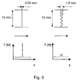
- FIG 4 is the comparison of a transverse punch 60 according to the prior art shown with a transverse punch 60 according to the invention, in waveform. Of the Arrow indicates the machine direction.
- the transverse punch 60 of the 15 mm wide web is made every 15 mm. After this known punching results in punched 42 with a length of 15 mm.
- the diecuts are also 15 mm long, but have wavy transverse edges.
- FIG. 5 shows the occurring force relationships in the transverse punches according to FIG Figure 4, in each case the punching force of a rotary die, once with straight cutting edge, once with wavy cutting edge.
- FIG. 6 shows various embodiments of inventively designed Punch lines.
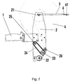
- the device for unrolling is located on a roller 4 Covering material web with punched articles 42, which are especially adhesive on both sides shown.
- the device is composed of several individual components.
- the central component is the holding plate 2, which serves to accommodate all other components, so a handle 1 which is screwed to the support plate 2.
- a handle 1 which is screwed to the support plate 2.
- the handle 1 By simply moving the handle 1 is a pulling and also in particular allows a sliding movement of the device during the dispensing process, Preferably, the device is pushed because a higher contact force, the pressure-sensitive self-adhesive is advantageous, ergonomic with sliding Movement is much easier to apply.
- a rotatably mounted on the support plate 2 pinch roller 22 is present, the during the dispensing process the Abdeckmaterialbahn with the punched 42 with the Substrate brings into contact and 21 is performed for the role 4 such that the Punches 42 during the dispensing of the Abdeckmaterialbahn on the Substrate be dispelled.
- the pressure roller 22 is in its material and diameter such that on the one hand a sufficient pressure for the bonding of self-adhesive equipped Stamped 42 is ensured and on the other hand, the Abdeckmaterialbahn of the Both sides self-adhesive diecuts 42 are easily removed during dispensing can. Then this is specific to the properties of the self-adhesive on both sides Punches 42 matched on the Abdeckmaterialbahn.
- the drive roller 23 is between the receptacle 21 for the roller 4 and the pressure roller 22 arranged.
- a rotatably mounted receiving roller 25 which receives the Abdeckmaterialbahn after dispensing the punched 42 and the in particular via a belt 24 by the movement of the drive roller 23 in rotation is offset.
- an adjustable axis 3 on an adjustable Positioning aid 6 is provided, in the form of a festschraubbaren, rotatable mounted shaft 61, via which the Abdeckmaterialbahn of the receptacle 21 for the role 4 is guided in the direction of drive roller 23.
- the pressure roller 22 is fixed on one side on the support plate 2 and carries on the another side a counter plate.
- the counter-plate and the holding plate 2 are in the Device that is pushed during the dispensing process, in the direction of Handle 1 extended executed.
- the counter-plate and the holding plate 2 are in their Form matched with the pinch roller 22 and the lever arm of the handle 1 so, that at the end of the dispensing operation the entire device is around the user can be easily tilted from this geometry resulting fulcrum.
- This rotational movement always succeeds in conjunction with the positioning aid 6, on the one hand the last diecut 42 still safe to donate, that is from the Abdeckmaterialbahn on the other hand, the following, later becomes glued punching 42 still held securely on the Abdeckmaterialbahn.
- the entire device is tuned so that both in an empty and at a full pickup roller 25, the positioning accuracy of the self-adhesive on both sides Diecuts 42 is not adversely affected. This concerns in particular the Gear ratio of the belt drive between the rollers 23 and 25
- a double-sided adhesive tape (tesafix 51965), which consists of two adhesive layers with a mass application of 100 g / m 2 on an interposed carrier film, namely a 12 micron thick polyester film, as well as a plastic-coated masking paper, with the width of 15 mm punched, in punched items of length also 15 mm.
- the rotary punching cylinder is designed as follows:
- Cross-grooves 1 measure 160 mm Longitudinal Number of Slots 15 corner radius ./.
- the rotary punching tool and the rotary punching machine become smaller Stamped line pressure less loaded in terms of power and load distribution.
- the force peaks occurring in rectilinear transverse punching cutters are at non-linear punching line geometries not available.
- An odd line shape creates higher cohesive forces between two cross-cut adhesive tape diecuts as a straight line punched form. Due to the cohesive forces between two cross-cut diecuts that over the Length of the punching line and can be influenced by the embodiment is the Equipment of cover papers with regard to their release properties with standardized To shape properties. Usually, cover papers with different silicone coatings on the Bottom and top provided. These different silicone coatings ensure the handling and the whereabouts of the diecuts when unrolling the double-sided adhesive tape roll on the desired side of the masking paper. With an odd line punched form are also cover papers with both sides identical silicone coating can be used, which with a straight cut line shape not possible. The silicone coatings on the cover paper must be in place be different in linear line shape.
Landscapes
- Life Sciences & Earth Sciences (AREA)
- Forests & Forestry (AREA)
- Engineering & Computer Science (AREA)
- Mechanical Engineering (AREA)
- Adhesive Tapes (AREA)
- Adhesives Or Adhesive Processes (AREA)
- Perforating, Stamping-Out Or Severing By Means Other Than Cutting (AREA)
Abstract
Description
- die einzelnen Klebebandabschnitte auf der Abdeckmaterialbahn in Form einer Rolle ohne weitere Hilfsmittel (zum Beispiel einer zweiten Abdeckung) konfektioniert und dargereicht werden können und
- die Klebebandabschnitte durch einen Abroller einfach gespendet werden können. Erfindungsgemäß können des weiteren als Abdeckmaterial hochverdichtete Glassine-Papiere, eingesetzt werden, die auf der oberen und/oder auf der unteren Seite mit einer Kunststoffbeschichtung versehen sind, wobei auf beiden der gegebenenfalls vorhandenen zwei Kunststoffbeschichtungen antiadhäsive Schichten aufgetragen sind, insbesondere Silikonbeschichtungen.In einer weiteren Ausführungsform der Erfindung wird ein Papierträger mit einer Dichte von 1,1 bis 1,25 g/cm3 als Abdeckmaterial eingesetzt, wobei der Papierträger im wesentlichen eine obere und eine untere Seite aufweist. Der Papierträger ist auf der oberen und/oder auf der unteren Seite mit einer Kunststoffbeschichtung versehen, wobei auf beiden der gegebenenfalls vorhandenen zwei Kunststoffbeschichtungen antiadhäsive Schichten aufgetragen sind, insbesondere Silikonbeschichtungen.Vorzugsweise weist der Papierträger beziehungsweise das Glassine-Papier eine Dichte auf von 1,12 bis 1,2 g/cm3, insbesondere 1,14 bis 1,16g/cm3. Weiter vorzugsweise weist der Papierträger beziehungsweise das Glassine-Papier ein Flächengewicht von 40 bis 120 g/m2, bevorzugt 50 bis 110 g/m2, ganz besonders bevorzugt 60 bis 100 g/m2, auf.Als Kunststoffbeschichtung werden insbesondere Polyolefine wie LDPE, HDPE, Mischungen der beiden zuvor genannten, zum Beispiel MDPE, PP oder PTE verwendet. Ganz besonders vorteilhaft ist LDPE.Die polybeschichteten Seiten des Papierträgers aus LDPE oder HDPE sind darüber hinaus matt oder glänzend herstellbar.Weiter vorzugsweise wird die Kunststoffbeschichtung mit 5 bis 30 g/m2, bevorzugt 10 bis 25 g/m2, ganz besonders bevorzugt 15 bis 20 g/m2, aufgetragen. Insbesondere bei Polyester kann der Auftrag auch bereits bei 2 bis 3 g/m2 erfolgen.Darüber hinaus stellt eine hervorragende Ausbildung der Erfindung die Tatsache dar, wenn als antiadhäsive Schichten zum Beispiel Silikon, Paraffin, Teflon oder Wachse verwendet werden. Dann können silikonfreie Trennschichten, zum Beispiel "non Silicone" von der Firma Rexam, oder silikonarme Trennschichten, zum Beispiel "Lo ex" von der Firma Rexam, eingesetzt werden.Als antiadhäsive Beschichtung wird vorzugsweise ein lösemittelfrei beschichtetes Silikon eingesetzt. Weiter vorzugsweise wird die antiadhäsive Beschichtung und/oder das lösemittelfrei beschichtete Silikon mit 0,8 bis 3 ,7 g /m2, bevorzugt 1,3 bis 3,2 g/m2, ganz besonders bevorzugt 1,8 bis 2,8 g/m2, aufgetragen. Aber auch lösemittelhaltige Systeme als antiadhäsive Beschichtung sind möglich, und zwar mit einer Auftragsmenge von insbesondere 0,3 bis 1 g/m2.Auf diese Weise ist gewährleistet, dass das Abdeckmaterial bei beidseitiger Polybeschichtung
- dimensionsstabile Eigenschaften (gute Planlage)
- eine geringe Dicke mit hoher Dickenkonstanz (enge Toleranzen, präzisere Stanzschnitte)
- und eine Schutzschicht gegen Anstanzungen des Papierkörpers
- eine geringe Dicke mit hoher Dickenkonstanz (enge Toleranzen, präzisere Stanzschnitte) und
- eine Schutzschicht gegen Anstanzungen des Papierkörpers aufweist. Die Bahn besteht vorzugsweise aus einer Klebemasseschicht oder aus einem Trägermaterial, das ein-oder beidseitig mit einer Klebemasse ausgerüstet ist.Als Trägermaterial werden vorzugsweise Papier, ein Papier-Polyolefin-Verbund und/oder eine Folie eingesetzt. Als Trägermaterial sind weiterhin prinzipiell Folien wie zum Beispiel BOPP oder MOPP, PET, PVC oder Vliese (auf Basis Cellulose oder Polymere) geeignet. Weiterhin kommen auch Schäume (zum Beispiel PUR, PE, PE/EVA, EPDM, PP, PE, Silikon, usw.) oder Trennpapiere (Kraft Papiere, polyolefinisch beschichtete Papiere) oder Trennfolien (PET, PP oder PE oder Kombinationen aus diesen Materialien) als Beschichtungssubstrate in Frage.Als Klebemassen können alle Haftklebemassen, wie sie zum Beispiel im SATAS, Handbook of Pressure Sensitive Adhesive Technology, Third Edition, erwähnt sind, eingesetzt werden. Insbesondere eignen sich Natur-/Synthesekautschuk- und acrylatbasierende Klebemassen, die aus der Schmelze oder Lösung aufgetragen werden können. Während der Herstellung, der Weiterverarbeitung oder der späteren Beanspruchung von Polymeren beziehungsweise von Polymermassen kann es zur Ausbildung hoher Orientierungsgrade der Makromoleküle in bevorzugte Richtungen im gesamten Polymerverband kommen; durch diese Orientierung, die auch gezielt herbeigeführt werden kann, lassen sich die Eigenschaften der entsprechenden Polymere steuern und in Hinblick auf gewünschte Verwendungen verbessern. Anisotrop orientierte Haftklebemassen besitzen die Tendenz, sich nach einer Streckung in eine vorgegebene Richtung durch das "entropieelastische Verhalten" in den Ausgangszustand zurückzubewegen. Für die Verwendung in den Stanzlingen sind prinzipiell alle Haftklebemassen geeignet, die eine Orientierung aufweisen, beispielsweise solche auf Basis von Natur- und Synthesekautschuken wie Butylkautschuk, Neopren, Butadien-Acrylnitril, Styrol-Butadien-Styrol- und Styrol-Isopren-Styrol-Copolymerisaten, ferner auf Basis von linearen Polyestern und Copolyestren, Polyurethanen, Polysiloxanelastomeren, auf Basis von Reinacrylaten, ganz besonders aber anisotrope Haftklebemassen auf Polyacrylatbasis. Solche anisotrop orientierten Acrylathaftklebemasssen zeigen als Schicht nach Stanzund/oder Schneidvorgängen eine Rückstellung der Haftklebeschicht an der Schneid- und Stanzkante, welche für das Ausstanzen nicht wieder zusammenfließender Stanzformen genutzt wird.Eine vorteilhafte Weiterentwicklung verwendet eine Haftklebemasse,
- welche durch eine radikalische Polymerisation erhältlich ist,
- welche zu mindestens 65 Gew.-% auf zumindest einem acrylischen Monomer aus der
Gruppe der Verbindungen der folgenden allgemeinen Formel basiert:


- Polymerisation eines Gemisches enthaltend zumindest ein Monomer auf Vinyl-, Acryloder Methacrylbasis oder eine Kombination dieser Monomere, wobei das mittlere Molekulargewicht der entstehenden Polymere oberhalb von 650.000 liegt,
- anschließender Extrusionsbeschichtung der Polymermasse,
- anschließender Vernetzung der Polymermasse auf dem Träger durch Bestrahlung mit Elektronenstrahlen.
- einem Griffstück, das an einer Halteplatte angebracht ist,
- einer auf der Halteplatte drehbar gelagerten Aufnahme für die Rolle Abdeckmaterialbahn,
- einer auf der Halteplatte drehbar gelagerten Andruckrolle, die während des Spendevorganges die Abdeckmaterialbahn mit den Stanzlingen mit den Untergrund in Kontakt bringt und über die die Abdeckmaterialbahn mit den Stanzlingen von der Aufnahme für die Rolle derart geführt wird, dass die Stanzlinge während des Spendevorganges von der Abdeckmaterialbahn auf den Untergrund verspendet werden,
- einer auf der Halteplatte drehbar gelagerten Antriebsrolle, über die die Abdeckmaterialbahn mit den Stanzlingen derart geführt wird, dass die Antriebsrolle synchron zur Geschwindigkeit der Abdeckmaterialbahn rotiert,
- einer auf der Halteplatte drehbar gelagerten Aufnahmerolle, die die Abdeckmaterialbahn nach dem Verspenden der Stanzlinge aufnimmt und die insbesondere über einen Riemen durch die Bewegung der Antriebsrolle in Rotation versetzt wird.
- Figur 1
- einen Stanzvorgang gemäß Stand der Technik, die dem die Querschneide exakt um 90° in Bezug auf die Maschinenrichtung angeordnet ist,
- Figur 2
- doppelseitige Klebebandstanzlinge mit Quersteg (Zwischenraum), wie sie aus dem Stand der Technik bekannt sind,
- Figur 3
- doppelseitige Klebebandstanzlinge ohne Quersteg (Zwischenraum), wie sie aus dem Stand der Technik bekannt sind,
- Figur 4
- den Vergleich einer Querstanzung gemäß dem Stande der Technik mit einer erfindungsgemäßen Querstanzung, und zwar in Wellenform,
- Figur 5
- die auftretenden Kräfteverhältnisse in den Querstanzungen gemäß Figur 4,
- Figur 6
- unterschiedliche Ausführungsformen der Querstanzung,
- Figur 7
- die Vorrichtung, mittels derer die mit dem erfindungsgemäßen Verfahren hergestellten Stanzlinge verspendet werden können,
- Figur 8
- die Auslegung des Rotationsstanzzylinders.
- Abwicklung der doppelseitig klebenden Klebebandrolle
- Anstanzen der Klebeband-Bahn mit Hilfe eines Rotationsstanzzylinders
- Aufwickeln der gestanzten Klebebandbahn zu einer Rolle.
| Verzahnung | 1/8 CP 20 |
| Zähnezahl | 71 |
| Umfang | 225,43 mm |
| Quer-Nuten | 1 |
| Maß | 160 mm |
| Längs-Nutenzahl | 15 |
| Eckenradius | ./. |
- Beidseitig klebende Stanzlinge zum Verkleben von Gegenständen wie zum Beispiel Leisten, Flachkabel, Papierstreifen oder Folienstreifen, insbesondere für die dauerhafte Fixierung von Flachkabeln auf Autodachinnenverkleidungen, bei der eine definierte Anzahl von einzelnen Klebebandstanzlingen auf den Untergrund aufgebracht werden.
- Einseitig klebende Stanzlinge auf einem Abdeckpapier zum Verkleben und Kennzeichnen von Gegenständen zum Beispiel zur Kennzeichnung von Kabeln, CDs, Disketten
Claims (5)
- Verfahren zum Stanzen von einer zumindest einseitig klebend ausgerüsteten Bahn, die sich auf einem Abdeckmaterial befindet, in einzelne Stanzlinge, dadurch gekennzeichnet, dass die Stanzlinie der Querstanzung, die die Bahn über die gesamte Breite der Bahn in einer sich nicht verzweigenden Linie in die Stanzlinge unterteilt, eine von einer Geraden abweichenden Form aufweist, wobei das Abdeckmaterial nicht oder unwesentlich angestanzt wird.
- Verfahren nach Anspruch 1, dadurch gekennzeichnet, dass die Querstanzung einen Winkel von im wesentlichen 90° zur Bahnrichtung aufweist.
- Verfahren nach Anspruch 1 oder 2, dadurch gekennzeichnet, dass die Stanzlinie bogenförmig, wellenförmig, sägezahnartig und/oder zick-zack-förmig ist.
- Verfahren nach zumindest einem der Ansprüche 1 bis 3, dadurch gekennzeichnet, dass die Bahn aus einer Klebemasseschicht oder aus einem Trägermaterial, das ein- oder beidseitig mit einer Klebemasse ausgerüstet ist, besteht.
- Verfahren nach zumindest einem der vorherigen Ansprüche, dadurch gekennzeichnet, dass auf dem Abdeckmaterial beidseitig eine antiadhäsive Beschichtung aufgebracht ist,
wobei sich die beiden antiadhäsiven Beschichtungen im Abweisungsgrad zur der gleichen Klebemasseschicht nicht unterscheiden.
Applications Claiming Priority (2)
| Application Number | Priority Date | Filing Date | Title |
|---|---|---|---|
| DE10332435A DE10332435A1 (de) | 2003-07-16 | 2003-07-16 | Verfahren zum Stanzen von einer zumindest einseitig klebend ausgerüsteten Bahn, die sich auf einem Abdeckmaterial befindet, in einzelne Stanzlinge |
| DE10332435 | 2003-07-16 |
Publications (3)
| Publication Number | Publication Date |
|---|---|
| EP1498229A2 true EP1498229A2 (de) | 2005-01-19 |
| EP1498229A3 EP1498229A3 (de) | 2005-07-06 |
| EP1498229B1 EP1498229B1 (de) | 2010-03-31 |
Family
ID=33461968
Family Applications (1)
| Application Number | Title | Priority Date | Filing Date |
|---|---|---|---|
| EP04013991A Expired - Lifetime EP1498229B1 (de) | 2003-07-16 | 2004-06-15 | Verfahren zum Stanzen von einer zumindest einseitig klebend ausgerüsteten Bahn, die sich auf einem Abdeckmaterial befindet, in einzelne Stanzlinge |
Country Status (7)
| Country | Link |
|---|---|
| US (1) | US20050011608A1 (de) |
| EP (1) | EP1498229B1 (de) |
| JP (1) | JP2005036225A (de) |
| KR (1) | KR20050009210A (de) |
| CN (1) | CN100351060C (de) |
| DE (2) | DE10332435A1 (de) |
| ES (1) | ES2340583T3 (de) |
Cited By (4)
| Publication number | Priority date | Publication date | Assignee | Title |
|---|---|---|---|---|
| EP1964621A1 (de) * | 2007-02-21 | 2008-09-03 | Welser Profile AG | Verfahren und Vorrichtung zum Herstellen von Profilen |
| CN111762616A (zh) * | 2020-07-15 | 2020-10-13 | 横店集团东磁股份有限公司 | 一种自动冲切贴附物料的机构及其实现方法 |
| CN114423695A (zh) * | 2019-08-20 | 2022-04-29 | 西川吉秀 | 半切割完毕双面胶带的制造方法及半切割完毕双面胶带贴附装置 |
| CN120156956A (zh) * | 2023-12-08 | 2025-06-17 | 上海昊佰智造精密电子股份有限公司 | 一种带有窄胶条的双面胶产品的加工方法 |
Families Citing this family (7)
| Publication number | Priority date | Publication date | Assignee | Title |
|---|---|---|---|---|
| FR2972135B1 (fr) * | 2011-03-01 | 2013-10-04 | Astea | Machine de transfert a chaud et sous pression d'une couche de protection d'un substrat |
| CN103509476A (zh) * | 2013-08-06 | 2014-01-15 | 昆山上艺电子有限公司 | 用于触摸屏面板的密封胶带 |
| DE102013217880A1 (de) * | 2013-09-06 | 2015-03-12 | Tesa Se | Latentreaktive Klebeprodukte mit verbesserter Stanzbarkeit und latentreaktive Klebfolienstanzlinge |
| ES2542826B1 (es) * | 2014-02-10 | 2016-05-19 | Alvarez Omar Daniel Briscik | Billetera digital de alta seguridad |
| ES2659454T3 (es) | 2015-02-23 | 2018-03-15 | Upm Specialty Papers Oy | Procedimiento para fabricar papel que comprende pasta quimiotermomecánica blanqueada apto para un revestimiento desprendible y productos y utilizaciones del mismo |
| DE102016007159B4 (de) * | 2016-06-13 | 2019-01-24 | Preh Car Connect Gmbh | Baugruppe mit zwei Bauteilen und zwei zwischen den Bauteilen angeordneten doppelseitigen Klebebandstreifen sowie Herstellungsverfahren für die Baugruppe |
| CN113696271B (zh) * | 2020-05-20 | 2022-11-08 | 昊佰电子科技(上海)有限公司 | 一种降低生产过程中掉片不良率的模切件的制作方法 |
Family Cites Families (16)
| Publication number | Priority date | Publication date | Assignee | Title |
|---|---|---|---|---|
| US5163349A (en) * | 1990-04-04 | 1992-11-17 | Brother Kogyo Kabushiki Kaisha | Tape cutting apparatus |
| JPH03287397A (ja) * | 1990-04-04 | 1991-12-18 | Brother Ind Ltd | テープ切断装置 |
| JPH07119135B2 (ja) * | 1990-10-03 | 1995-12-20 | ブラザー工業株式会社 | テープの端部処理装置 |
| US5562789A (en) * | 1992-05-13 | 1996-10-08 | Wallace Computer Services, Inc. | Label-equipped web method |
| DE4300411C2 (de) * | 1993-01-09 | 2003-10-16 | Meto International Gmbh | Etikett und Verfahren zu dessen Herstellung |
| US5370420A (en) * | 1993-01-25 | 1994-12-06 | Moore Business Forms, Inc. | Pressure sensitive label for high speed laser printers |
| US5407718B1 (en) * | 1993-08-05 | 1999-03-02 | Avery Dennison Corp | Transparent paper label sheets |
| GB2288162B (en) * | 1994-03-30 | 1997-11-26 | Harrison & Sons Ltd | Self-adhesive stamps |
| US6270871B1 (en) * | 1996-09-27 | 2001-08-07 | Avery Dennison Corporation | Overlaminated pressure-sensitive adhesive construction |
| DE19641094C1 (de) * | 1996-10-04 | 1997-06-26 | Beiersdorf Ag | Verfahren zum verlustfreien Stanzen von klebenden Stanzlingen |
| US6464818B1 (en) * | 1996-10-04 | 2002-10-15 | Tesa Ag | Method of wasteless punching of adhesive punched items |
| US5975582A (en) * | 1997-12-04 | 1999-11-02 | Pharmagraphica (Midwest), L.L.C. | Self-adhesive extended text label having laminate cover and adhesive-free gap |
| DE19938693A1 (de) * | 1999-08-14 | 2001-02-22 | Beiersdorf Ag | Klebfolienstreifen und seine Verwendung |
| DE10107294A1 (de) * | 2001-02-16 | 2003-02-20 | Tesa Ag | Trägermaterialbahn, auf der beidseitig selbstklebend ausgerüstete Klebebandabschnitte angeordnet sind, sowie die Verwendung dieser in einem Handetikettiergerät |
| US20030087089A1 (en) * | 2001-11-08 | 2003-05-08 | Rodriguez Peter A. | Roll of adhesive labels for cutting tape |
| US6939594B2 (en) * | 2003-02-10 | 2005-09-06 | Inprint Systems, Inc. | Self-adhesive labels and manufacture thereof |
-
2003
- 2003-07-16 DE DE10332435A patent/DE10332435A1/de not_active Withdrawn
-
2004
- 2004-04-21 US US10/830,172 patent/US20050011608A1/en not_active Abandoned
- 2004-06-15 DE DE502004010955T patent/DE502004010955D1/de not_active Expired - Lifetime
- 2004-06-15 ES ES04013991T patent/ES2340583T3/es not_active Expired - Lifetime
- 2004-06-15 EP EP04013991A patent/EP1498229B1/de not_active Expired - Lifetime
- 2004-07-05 JP JP2004198487A patent/JP2005036225A/ja not_active Ceased
- 2004-07-15 KR KR1020040055205A patent/KR20050009210A/ko not_active Withdrawn
- 2004-07-16 CN CNB2004100712464A patent/CN100351060C/zh not_active Expired - Fee Related
Cited By (4)
| Publication number | Priority date | Publication date | Assignee | Title |
|---|---|---|---|---|
| EP1964621A1 (de) * | 2007-02-21 | 2008-09-03 | Welser Profile AG | Verfahren und Vorrichtung zum Herstellen von Profilen |
| CN114423695A (zh) * | 2019-08-20 | 2022-04-29 | 西川吉秀 | 半切割完毕双面胶带的制造方法及半切割完毕双面胶带贴附装置 |
| CN111762616A (zh) * | 2020-07-15 | 2020-10-13 | 横店集团东磁股份有限公司 | 一种自动冲切贴附物料的机构及其实现方法 |
| CN120156956A (zh) * | 2023-12-08 | 2025-06-17 | 上海昊佰智造精密电子股份有限公司 | 一种带有窄胶条的双面胶产品的加工方法 |
Also Published As
| Publication number | Publication date |
|---|---|
| KR20050009210A (ko) | 2005-01-24 |
| DE10332435A1 (de) | 2005-02-10 |
| ES2340583T3 (es) | 2010-06-07 |
| CN100351060C (zh) | 2007-11-28 |
| JP2005036225A (ja) | 2005-02-10 |
| EP1498229A3 (de) | 2005-07-06 |
| US20050011608A1 (en) | 2005-01-20 |
| CN1575942A (zh) | 2005-02-09 |
| EP1498229B1 (de) | 2010-03-31 |
| DE502004010955D1 (de) | 2010-05-12 |
Similar Documents
| Publication | Publication Date | Title |
|---|---|---|
| EP2391686B1 (de) | Verwendung von träger verstärkten hitzeaktivierbaren klebemassen | |
| DE69823518T2 (de) | Klebeband für ein Windelverschlusssystem | |
| CH630110A5 (de) | Selbstklebendes material. | |
| EP1422176B1 (de) | Vorrichtung zum Abrollen von einer auf einer Rolle befindlichen Trägermaterialbahn mit insbesondere beidseitig klebend ausgerüsteten Klebebandabschnitten | |
| EP1498229B1 (de) | Verfahren zum Stanzen von einer zumindest einseitig klebend ausgerüsteten Bahn, die sich auf einem Abdeckmaterial befindet, in einzelne Stanzlinge | |
| DE2225618A1 (de) | Klebstoff-Auftragband | |
| EP2285926A1 (de) | Verstreckte thermoplaste zur verklebung von metallteilen auf kunststoffen, gläsern und metallen und verfahren zu ihrer herstellung | |
| EP1453926B1 (de) | Verfahren zur herstellung haftklebriger stanzprodukte | |
| EP3613819A1 (de) | Klebeband zum ummanteln von langgestrecktem gut wie insbesondere kabelsätzen und verfahren zur ummantelung | |
| EP1453927A1 (de) | Verfahren zur herstellung haftklebriger stanzprodukte | |
| DE10349107A1 (de) | Verfahren zum Verkleben von Kabelbäumen auf Untergründen wie die Innenraum-Dekorteile eines PKWs, insbesondere Dachhimmel, Türseitenteil, Kofferraumdeckel | |
| DE102011079544A1 (de) | Abroller | |
| EP1628856B1 (de) | Verfahren zum verkleben von flachbandkabeln auf untergründen wie die innenraum-dekorteile eines pkws, insbesondere dachhimmel, türseitenteil, kofferraumdeckel | |
| EP1777276B1 (de) | Verfahren zur Herstellung anisotroper Haftklebemassen | |
| EP3173452A1 (de) | Klebeband und seine verwendung | |
| DE10116770A1 (de) | Schneidemaschine für das Ablängen von selbstklebend ausgerüsteten textilen Trägern | |
| EP1233046B1 (de) | Trägermaterialbahn, auf der beidseitig selbstklebend ausgerüstete Klebebandabschnitte angeordnet sind, sowie die Verwendung dieser in einem Handetikettiergerät | |
| DE10335238A1 (de) | Verfahren zum Verkleben von Flachbandkabeln auf Untergründen wie die Innenraum-Dekorteile eines PKWs, insbesondere Dachhimmel, Türseitenteil, Kofferraumdeckel | |
| EP0965624A2 (de) | Stripfähiges Schablonenband und seine Verwendung | |
| DE2856009C2 (de) | Verfahren zur Herstellung eines Selbstklebebandes | |
| EP1367107A2 (de) | Verwendung eines Klebebands zur Abdeckung bei Maler- und Lackieranwendungen | |
| EP1589064A1 (de) | Verwendung eines doppelseitig klebend ausgerüsteten Schaumstoff-Klebebands zum Befestigen von strukturierten Flachleitungen insbesondere auf Untergründen wie die Innenraum-Dekorteile eines Pkws, insbesondere Dachhimmel, Türseitenteil, Kofferraumdeckel | |
| EP1272584A1 (de) | Verwendung eines hochdichten papierträgers als trägerbahn in einem abdeckmaterial für ein klebeband | |
| EP1789510A1 (de) | Klebeband | |
| DE102005061769A1 (de) | Verfahren zur Herstellung von Abdeckungen für klebende Erzeugnisse |
Legal Events
| Date | Code | Title | Description |
|---|---|---|---|
| PUAI | Public reference made under article 153(3) epc to a published international application that has entered the european phase |
Free format text: ORIGINAL CODE: 0009012 |
|
| AK | Designated contracting states |
Kind code of ref document: A2 Designated state(s): AT BE BG CH CY CZ DE DK EE ES FI FR GB GR HU IE IT LI LU MC NL PL PT RO SE SI SK TR |
|
| AX | Request for extension of the european patent |
Extension state: AL HR LT LV MK |
|
| PUAL | Search report despatched |
Free format text: ORIGINAL CODE: 0009013 |
|
| AK | Designated contracting states |
Kind code of ref document: A3 Designated state(s): AT BE BG CH CY CZ DE DK EE ES FI FR GB GR HU IE IT LI LU MC NL PL PT RO SE SI SK TR |
|
| AX | Request for extension of the european patent |
Extension state: AL HR LT LV MK |
|
| 17P | Request for examination filed |
Effective date: 20060109 |
|
| AKX | Designation fees paid |
Designated state(s): DE ES FR GB IT |
|
| 17Q | First examination report despatched |
Effective date: 20061206 |
|
| RAP1 | Party data changed (applicant data changed or rights of an application transferred) |
Owner name: TESA SE |
|
| GRAP | Despatch of communication of intention to grant a patent |
Free format text: ORIGINAL CODE: EPIDOSNIGR1 |
|
| GRAS | Grant fee paid |
Free format text: ORIGINAL CODE: EPIDOSNIGR3 |
|
| GRAA | (expected) grant |
Free format text: ORIGINAL CODE: 0009210 |
|
| AK | Designated contracting states |
Kind code of ref document: B1 Designated state(s): DE ES FR GB IT |
|
| REG | Reference to a national code |
Ref country code: GB Ref legal event code: FG4D Free format text: NOT ENGLISH |
|
| REF | Corresponds to: |
Ref document number: 502004010955 Country of ref document: DE Date of ref document: 20100512 Kind code of ref document: P |
|
| REG | Reference to a national code |
Ref country code: ES Ref legal event code: FG2A Ref document number: 2340583 Country of ref document: ES Kind code of ref document: T3 |
|
| PLBE | No opposition filed within time limit |
Free format text: ORIGINAL CODE: 0009261 |
|
| STAA | Information on the status of an ep patent application or granted ep patent |
Free format text: STATUS: NO OPPOSITION FILED WITHIN TIME LIMIT |
|
| 26N | No opposition filed |
Effective date: 20110104 |
|
| PGFP | Annual fee paid to national office [announced via postgrant information from national office to epo] |
Ref country code: ES Payment date: 20110624 Year of fee payment: 8 Ref country code: FR Payment date: 20110630 Year of fee payment: 8 |
|
| PGFP | Annual fee paid to national office [announced via postgrant information from national office to epo] |
Ref country code: GB Payment date: 20110620 Year of fee payment: 8 |
|
| PGFP | Annual fee paid to national office [announced via postgrant information from national office to epo] |
Ref country code: IT Payment date: 20110621 Year of fee payment: 8 |
|
| GBPC | Gb: european patent ceased through non-payment of renewal fee |
Effective date: 20120615 |
|
| PG25 | Lapsed in a contracting state [announced via postgrant information from national office to epo] |
Ref country code: IT Free format text: LAPSE BECAUSE OF NON-PAYMENT OF DUE FEES Effective date: 20120615 |
|
| REG | Reference to a national code |
Ref country code: FR Ref legal event code: ST Effective date: 20130228 |
|
| PG25 | Lapsed in a contracting state [announced via postgrant information from national office to epo] |
Ref country code: FR Free format text: LAPSE BECAUSE OF NON-PAYMENT OF DUE FEES Effective date: 20120702 Ref country code: GB Free format text: LAPSE BECAUSE OF NON-PAYMENT OF DUE FEES Effective date: 20120615 |
|
| REG | Reference to a national code |
Ref country code: ES Ref legal event code: FD2A Effective date: 20131021 |
|
| PG25 | Lapsed in a contracting state [announced via postgrant information from national office to epo] |
Ref country code: ES Free format text: LAPSE BECAUSE OF NON-PAYMENT OF DUE FEES Effective date: 20120616 |
|
| REG | Reference to a national code |
Ref country code: DE Ref legal event code: R081 Ref document number: 502004010955 Country of ref document: DE Owner name: TESA SE, DE Free format text: FORMER OWNER: TESA SE, 20253 HAMBURG, DE |
|
| PGFP | Annual fee paid to national office [announced via postgrant information from national office to epo] |
Ref country code: DE Payment date: 20190619 Year of fee payment: 16 |
|
| REG | Reference to a national code |
Ref country code: DE Ref legal event code: R119 Ref document number: 502004010955 Country of ref document: DE |
|
| PG25 | Lapsed in a contracting state [announced via postgrant information from national office to epo] |
Ref country code: DE Free format text: LAPSE BECAUSE OF NON-PAYMENT OF DUE FEES Effective date: 20210101 |