EP1498076B1 - Verpackung für chirurgisches Nahtmaterial - Google Patents
Verpackung für chirurgisches Nahtmaterial Download PDFInfo
- Publication number
- EP1498076B1 EP1498076B1 EP04016955A EP04016955A EP1498076B1 EP 1498076 B1 EP1498076 B1 EP 1498076B1 EP 04016955 A EP04016955 A EP 04016955A EP 04016955 A EP04016955 A EP 04016955A EP 1498076 B1 EP1498076 B1 EP 1498076B1
- Authority
- EP
- European Patent Office
- Prior art keywords
- suture
- cover
- package
- base
- recited
- Prior art date
- Legal status (The legal status is an assumption and is not a legal conclusion. Google has not performed a legal analysis and makes no representation as to the accuracy of the status listed.)
- Expired - Lifetime
Links
- 238000004806 packaging method and process Methods 0.000 title description 15
- 238000000034 method Methods 0.000 claims description 12
- 239000003356 suture material Substances 0.000 claims description 12
- 238000004804 winding Methods 0.000 claims description 6
- 230000000630 rising effect Effects 0.000 claims description 4
- 238000002347 injection Methods 0.000 claims description 2
- 239000007924 injection Substances 0.000 claims description 2
- 229920000728 polyester Polymers 0.000 claims description 2
- 229920000098 polyolefin Polymers 0.000 claims description 2
- 229920005992 thermoplastic resin Polymers 0.000 claims 2
- 238000005192 partition Methods 0.000 description 7
- 230000008901 benefit Effects 0.000 description 4
- 239000000853 adhesive Substances 0.000 description 3
- 230000001070 adhesive effect Effects 0.000 description 3
- 239000000463 material Substances 0.000 description 3
- 238000004519 manufacturing process Methods 0.000 description 2
- 238000012986 modification Methods 0.000 description 2
- 230000004048 modification Effects 0.000 description 2
- -1 polyethylene Polymers 0.000 description 2
- 239000004677 Nylon Substances 0.000 description 1
- 239000004698 Polyethylene Substances 0.000 description 1
- 239000004743 Polypropylene Substances 0.000 description 1
- 230000000712 assembly Effects 0.000 description 1
- 238000000429 assembly Methods 0.000 description 1
- 230000000694 effects Effects 0.000 description 1
- 239000011888 foil Substances 0.000 description 1
- 230000036512 infertility Effects 0.000 description 1
- 238000001746 injection moulding Methods 0.000 description 1
- 229920001778 nylon Polymers 0.000 description 1
- 229920000573 polyethylene Polymers 0.000 description 1
- 229920001155 polypropylene Polymers 0.000 description 1
- 125000006850 spacer group Chemical group 0.000 description 1
- 238000001356 surgical procedure Methods 0.000 description 1
- 238000003856 thermoforming Methods 0.000 description 1
- 229920001169 thermoplastic Polymers 0.000 description 1
- 239000012815 thermoplastic material Substances 0.000 description 1
- 239000004416 thermosoftening plastic Substances 0.000 description 1
Images




Classifications
-
- A—HUMAN NECESSITIES
- A61—MEDICAL OR VETERINARY SCIENCE; HYGIENE
- A61B—DIAGNOSIS; SURGERY; IDENTIFICATION
- A61B17/00—Surgical instruments, devices or methods
- A61B17/04—Surgical instruments, devices or methods for suturing wounds; Holders or packages for needles or suture materials
- A61B17/06—Needles ; Sutures; Needle-suture combinations; Holders or packages for needles or suture materials
- A61B17/06114—Packages or dispensers for needles or sutures
- A61B17/06133—Packages or dispensers for needles or sutures of parallelepipedal shape, e.g. made of rectangular or slightly oval panels
-
- A—HUMAN NECESSITIES
- A61—MEDICAL OR VETERINARY SCIENCE; HYGIENE
- A61B—DIAGNOSIS; SURGERY; IDENTIFICATION
- A61B17/00—Surgical instruments, devices or methods
- A61B17/04—Surgical instruments, devices or methods for suturing wounds; Holders or packages for needles or suture materials
- A61B17/06—Needles ; Sutures; Needle-suture combinations; Holders or packages for needles or suture materials
- A61B17/06114—Packages or dispensers for needles or sutures
- A61B2017/06142—Packages or dispensers for needles or sutures having needle- or suture- retaining members, e.g. holding tabs or needle parks
Definitions
- the present invention relates to a suture package and to a method of forming a surgical suture package.
- the invention may be particularly applied to methods and apparatus for packaging surgical sutures.
- a common form of surgical suture package is made of a folded stiff treated paper suture holder contained in a sterile, hermetically sealed envelope. This envelope is further sealed in a second, usually clear, thermoplastic heat-sealed envelope outer wrap to maintain the sterility of suture holder and inner envelope.
- the outer clear wrap is opened, typically in the operating room, and the sealed sterile inner envelope is placed in a sterile area. Operating room personnel then open the inner envelope when access to the suture is needed.
- Packages for surgical sutures having needles attached at one or both ends are constructed according to the nature of the suture material and to how the sutures will be used. Generally, the package holds the suture and attached needles in place, protects them during handling and storage, and allows ready access to the suture for removal with minimum handling at the time the suture is to be used.
- suture packages An important aspect of the design and manufacture of suture packages is that the suture should be removable without becoming entangled with itself, kinked, coiled or bound in undesired ways.
- the nature of the suture material itself may impose limitations on the configuration of the package, how the suture is placed within the package, the placement of the needles, or how the suture is drawn from the package.
- U. S. Patent No. 6,076,659 An exemplary packaging for surgical suture material is disclosed in U. S. Patent No. 6,076,659 .
- the '659 patent discloses a packaging for surgical suture material which has a base from which a wall extends in a spiral manner.
- the wall defines a suture duct within the area defined by the base.
- the suture duct opens at its first end into a suture-removal area.
- a cover is located above the suture duct.
- the spiral wall is provided on its outward-facing side with suture-deflector protrusions spaced apart from one another in the course of the suture duct.
- a drawback in the case of the previously known packaging for surgical suture material is that, when the surgical suture material is being removed, the suture can pull tight in the suture retaining area in which it is guided over several spiral turns. That is, in the attempt to remove the suture from the packaging, the direction of the pulling force often causes the suture to move toward locations within the packaging which could cause the suture to become bound.
- the suture can move within the suture retaining area into an area which is formed by a junction between the wall extending like a spiral and the cover.
- the suture retaining area is defined by the spiral wall, the base and the cover.
- the wall in the suture package in the '659 patent, as well as many other prior art suture packages extends from the bottom of the package toward the cover.
- a gap is frequently formed at a location which is defined by the junction of the wall and the cover. It is not uncommon for the suture to become wedged in the gap, thereby making further removal of the surgical suture material much more difficult or impossible.
- Suture packages are disclosed in US-A-6076659 and US-A-5695138 .
- a suture package comprising: a base; a cover having a circumference and configured to be placed adjacent to the base to form the suture package; an outside wall rising from the base and extending like an oval around an outer circumference of the base, the outside wall having a predetermined height and an upper rim such that the upper rim engages the cover at the circumference thereof when the cover is placed adjacent the base, to form an outer wall of the suture package; a suture retaining area defined within the package, between said outside wall and an inner boundary configured to follow the shape of the suture retaining area; and a plurality of sets of suture retaining area protrusions having a height which is substantially equivalent to the height of the outside wall and extending from a lower surface of the cover, the sets being displaced radially from a center of the cover between the inner boundary and the outside wall to divide the suture retaining area into two or more separate retaining areas to provide for a corresponding two or more revolutions of suture.
- a method of forming a surgical suture package comprising the steps of: forming a base member having an outside wall rising a predetermined height from an upper surface and extending like an oval around a circumference of the base member; forming a cover member having a plurality of sets of suture retaining protrusions having a height which is substantially equivalent to the height of the outside wall and extending from a lower surface of the cover member, wherein the plurality of sets of suture retaining protrusions are radially displaced and extend from the lower surface of the cover member to divide a suture retaining area, defined between the outside wall and an inner boundary configured to follow the shape of the suture retaining area, into two or more separate retaining areas to provide for corresponding two or more revolutions of a surgical suture; winding a surgical suture within at least one of the separate retaining areas formed on the lower surface of the cover member; and moving the cover member adjacent to the base member to form an enclosed surgical suture package
- One advantage achievable with embodiments of the present invention is to provide a packaging for surgical suture material in such a way that surgical suture material situated in the packaging can be removed without problems. Accordingly, embodiments of the present invention can provide novel methods and apparatus for surgical suture packaging that eliminate many problems associated with the prior art suture packages.
- FIGs. 1A and 1B there is shown a top view and a side cross-sectional view, respectively, of an embodiment of a suture package in accordance with the present invention.
- the package has a base 5 and a cover 10.
- An outside wall 15 rises from base 5 and extends like an oval around a circumference of base 5.
- Outside wall 15 has an upper rim 20 and a lower rim 25.
- Lower rim 25 is connected to the base 5.
- Outside wall 15 is designed having a predetermined height such that upper rim 20 engages cover 10, preferably at the circumference thereof.
- a suture retaining area 30 is defined on an outer boundary by outside wall 15, and on an inner boundary by an inner or interior wall 35.
- Interior wall 35 preferably extends downward from cover 10. Unlike outside wall 15, interior wall 35 is not a continuous loop. Instead, interior wall 35 has a first end and a second end which will be described in further detail below. Adjacent to the first end of interior wall 35, an opening is defined which allows a first end of a suture 45 to enter into the suture retaining area 30.
- Interior wall 35 is also configured to follow the shape of the suture retaining area 30. Thus, at the point of the opening formed by interior wall 35, the end of the interior wall 35 is offset from any other portion of interior wall 35. This offset is necessary to maintain the shape of the suture retaining area 30 and to provide an opening for the suture 45 to access the suture retaining area 30.
- interior wall 35 may define an outer boundary of a plateau region in the center of cover 10.
- the height of the plateau region (also referred to as suture-removal area 85) is configured to be equivalent to the height of suture retaining area protrusions 40 less the thickness of a needle 70.
- a needle 70 may be positioned on the plateau in suture-removal area 85, on the outside surface of cover 10.
- a spacer may be placed on the plateau in suture-removal area 85.
- interior wall 35 defines an oval opening within cover 10. In that case, it is preferred that a needle park 75 is attached to base 5 within the suture-removal area 85. Therefore, surgical personnel have the ability to access and remove needle 70 through the opening within cover 10.
- Extending downward from cover 10 is structure that partitions the suture package into one or more suture retaining areas. More specifically, a plurality of sets of four suture retaining area protrusions 40 defines a corresponding number of suture retaining areas. The sets of suture retaining area protrusions 40 are displaced radially from a center of the cover 10. It is also contemplated that the sets of suture retaining area protrusions may be configured as more or less than four retaining area protrusions such that more or less suture retaining areas are defined. Additionally, it is contemplated that the suture retaining area protrusions may be configured as one or more continuous walls which define one or more suture retaining areas.
- Suture retaining area protrusions 40 are elongated finger members having a height which is substantially equivalent to the height of outside wall 15. Suture retaining area protrusions 40 are connected on a first end to the bottom surface of cover 10. A second end of suture retaining area protrusions 40 has a post 60 extending therefrom. Posts 60 are dimensioned to fit within holes 65 which are formed in base 5. Holes 65 may also be dimples or recesses. Posts 60 may also be heat staked or otherwise welded to base 5 to secure the cover 10 to the base 5. As cover 10 and base 5 are joined together, posts 60 extending from suture retaining area protrusions 40 engage holes 65 which are defined by base 5. This arrangement provides structural support to the suture package.
- the ends of the protrusions 40 may, alternatively, be deformed in the manner of rivets after the cover 10 has been fitted onto the base 5 with the wall 15.
- Other and/or additional types of connection between the wall 15 and the cover 10 are possible.
- the use of catches, which project at the periphery of the cover 10 and engage with suitable counterparts at the wall 15, is conceivable.
- the suture retaining area protrusions 40 define the suture retaining areas 30 on the bottom of cover 10.
- the embodiment illustrated in FIGs. 1A and 1B includes a plurality of sets of four suture retaining area protrusions 40 extending radially outward between interior wall 35 and outside wall 15.
- a suture retaining area 30 defines and provides for four revolutions of suture 45.
- the suture retaining area protrusions 40 are only positioned in the end sections of the suture package.
- the two straight sides 80 of the suture package do not contain any protrusions.
- suture 45 is not restrained within defined retaining areas as the suture traverses each of the two sides 80.
- a first end 50 of the suture retaining area 30 opens into a suture-removal area 85 which, in the embodiment illustrated in FIGs. 1A and 1B is arranged in the zone surrounded by the suture retaining area 30.
- the second end 55 of the suture retaining area 30 is closed, see FIG. 1A .
- the suture retaining area 30 is closed to the bottom by base 5.
- needle park assembly 75 is provided within the central section of the suture-removal area 5 on an outer surface of cover 10 or an inner surface of base 5.
- the structure of needle park assembly 75 may be known to one having ordinary skill in the art. See, for example, U.S. Patent Nos. 6,481,569 , 5,788,062 , 5,472,081 , 5,180,053 , 5,131,533 , 5,099,994 , and 4,424,898 .
- cover 10 includes an opening which permits free access to the suture-removal area 85.
- the opening may be a partial opening in the cover, or a more extensive opening, the advantages of each of which will be described below.
- Surgical personnel can gain access to the needle and suture through the opening in cover 10 and remove the needle suture combination by disengaging needle 70 from needle park 75 and then pulling the suture 45 from suture retaining area 30.
- the needle 70 is positioned within the inner space defined by the suture 45. This configuration further assists in the removal of the needle-suture combination from the package.
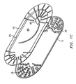
- FIG. 1C illustrates a perspective view of an embodiment of a suture package in accordance with the present invention. Illustrated in FIG. 1C are base 5 and cover 10. A needle 70 is shown positioned within a recessed suture-removal area 85 of cover 10. Thus, needle 70 is positioned on an exterior surface of the suture package. It is also contemplated that needle 70 may reside on base 5. In that case, the needle 70 may be retrieved from the suture package through an opening defined in cover 10 which is larger than opening 90.
- Suture-removal area 85 is defined on an outer circumference by interior wall 35 which extends from a bottom surface of cover 10. Also extending from the bottom surface of cover 10 is a plurality of suture retaining area protrusions 40. When cover 10 is placed against base 5, suture retaining area protrusions 40 engage holes 65 formed in base 5.
- a suture retaining area 30 is defined on an outer boundary by outside wall 15, and an inner boundary by interior wall 35. At the end portion of the suture package, suture retaining area 30 is divided into two or more separate retaining areas by suture retaining area protrusions 40.
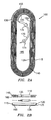
- FIGs. 2A and 2B there is shown a top view and a side cross-sectional view, respectively, of an embodiment of a suture package 100 in accordance with the present invention.
- the package has a base 105 and a cover 110.
- An outside wall 115 rises from base 105 and extends like an oval around a circumference of base 105.
- Outside wall 115 has an upper rim 120 and a lower rim 125.
- Lower rim 125 is connected to the base 105.
- Outside wall 115 is designed having a predetermined height such that upper rim 120 engages cover 110, preferably at the circumference thereof.
- a suture retaining area 130 is defined on an outer boundary by outside wall 115, and on an inner boundary by an inner or interior wall 135.
- Interior wall 135 preferably extends downward from cover 110. Unlike outside wall 115, interior wall 135 is not a continuous loop. Instead, interior wall 13 5 has a first end and a second end which will be described in further detail below. Adjacent to the first end of interior wall 13 5, an opening is defined which allows a first end of a suture 145 to enter into the suture retaining area 130.
- Interior wall 135 is also configured to follow the shape of the suture retaining area 130. Thus, at the point of the opening formed by interior wall 135, the end of the interior wall 135 is offset from any other portion of wall 135. This offset is necessary to maintain the shape of the suture retaining area 130 and to provide an opening for the suture 145 to access the suture retaining area 130.
- Extending downward from cover 110 is structure which partitions the suture package into one or more suture retaining areas. More specifically, a plurality of sets of four suture retaining area protrusions 140 defines a corresponding number of suture retaining areas. The sets of suture retaining area protrusions 140 are displaced radially from a center of the cover 105. It is also contemplated that the sets of suture retaining area protrusions may be configured as more or less than four retaining area protrusions such that more or less suture retaining areas are defined. Additionally, it is contemplated that the suture retaining area protrusions may be configured as one or more continuous walls which define one or more suture retaining areas.
- Suture retaining area protrusions 140 are elongated finger members having a height which is substantially equivalent to the height of outside wall 115. Suture retaining area protrusions 140 are connected on a first end to the bottom surface of cover 110. A second end of suture retaining area protrusion 140 has a post 160 extending therefrom. Posts 160 are dimensioned to fit within holes 165 which are formed in base 105. Holes 165 may also be dimples or recesses. Posts 160 may also be heat staked or otherwise welded to base 105 to secure the cover 110 to the base 105. As cover 110 and base 105 are joined together, posts 160 extending from suture retaining area protrusions 140 engage holes 165 which are defined by base 105.
- the ends of the protrusions 140 may, alternatively, be deformed in the manner of rivets after the cover 110 has been fitted onto the base 105 with the wall 115.
- Other and/or additional types of connection between the wall 115 and the cover 110 are possible.
- the use of catches, which project at the periphery of the cover 110 and engage with suitable counterparts at the wall 115 is conceivable.
- the suture is removed through the cover, there will be a tendency for the suture to move in the direction of the cover 110, which is away from any gap which may form at the junction of the suture retaining area protrusions 140 and base 105.
- this configuration is able to further the objective of increasing the reliability of the removability of the suture.
- the alternative embodiments described herein include various structural differences, a common feature of each of the embodiments is that the structure which forms the suture retaining areas extends from a bottom surface of the cover.
- the suture retaining area protrusions 140 define the suture retaining areas 13 0 on the bottom of cover 110.
- the embodiment illustrated in FIGS. 2A and 2B includes a plurality of sets of four suture retaining area protrusions 140 extending radially outward between interior wall 13 5 and outside wall 115.
- a suture retaining area 130 defines and provides for four revolutions of suture 145.
- a first end 150 of the suture retaining area 130 opens into a suture-removal area 185 which in the embodiments illustrated in FIGS. 2A and 2B is arranged in the zone surrounded by the suture retaining area 130.
- the second end 155 of the suture retaining area 130 is closed, see FIG. 2A .
- the suture retaining area 130 is closed to the bottom by base 105.
- the suture Prior to being placed within a suture package, the suture is typically attached to a needle to provide a needle-suture-combination. That is, a needle 170 is fitted onto an end of the suture 145.
- a needle park assembly 175 is provided within the central section of the suture-removal area 185 on an outer surface of cover 110 or an inner surface of base 105.
- Cover 110 includes an opening which permits free access to the suture-removal area 185. Surgical personnel can gain access to the needle and suture through the opening in cover 110 and remove the suture by disengaging needle 170 from needle park 175 and then pulling the suture 145 from suture retaining area 130.
- the needle 170 is positioned within the inner space defined by the suture 145. This configuration further assists in the removal of the suture from the package.
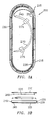
- FIGs. 3A and 3B illustrate a top view and a side cross-sectional view, respectively, of an embodiment of a suture package 200 in accordance with the present invention.
- the package has a base 205 and a cover 210.
- An outside wall 215 rises from base 205 and extends like an oval around a circumference of base 205.
- Outside wall 215 has an upper rim 220 and a lower rim 225.
- Lower rim 225 is connected to the base 205.
- Outside wall 215 is designed having a predetermined height such that upper rim 220 engages cover 210, preferably at the circumference thereof.
- the outer circumference of cover 210 is joined with the upper rim 220 of outside wall 215 to form an outer wall of the closed suture package 200.
- An oval suture retaining area 230 is defined on an outer boundary by outside wall 215, and on an inner boundary by an interior wall 235.
- Interior wall 235 preferably extends downward from cover 210.
- interior wall 23 is not a continuous loop. Instead, interior wall 235 has a first end 250 and a second end 255. Adjacent to the first end 250, an opening is defined which allows a first end of a suture 245 to enter into the oval suture retaining area 230. Additionally, a gap is maintained between the first and second ends 250, 255 to provide access of a needle 270 to a region in the center of the suture winding.
- Interior wall 235 includes a plurality of posts 260 spaced apart and extending therefrom.
- the height of interior wall 23 5 is substantially equivalent to the height of outside wall 215.
- Posts 260 are dimensioned to fit within holes 265 which are formed in base 205. Holes 265 may also be dimples or recesses. Therefore, as cover 210 and base 205 are joined together, posts 260 extending from interior wall engage holes 265 which are defined by base 205. This arrangement provides structural support to the suture package.
- the posts 260 may, alternatively, be deformed in the manner of rivets after the cover 210 has been fitted onto the base 205 with the wall 215.
- Other and/or additional types of connection between the wall 215 and the cover 210 are possible. Thus, e.g., the use of catches, which project at the periphery of the cover 210 and engage with suitable counterparts at the wall 215, is conceivable.
- needle 270 Prior to being placed within a suture package, needle 270 is fitted onto an end of the suture 245.
- a needle park assembly 275 is provided within the central section of the suture-removal area 285 on the exterior surface of cover 210 or an inner surface of base 205.
- Cover 210 includes an opening which permits free access to the suture-removal area 285. Surgical personnel can gain access to the needle and suture through the opening in cover 210 and remove the suture by disengaging needle 270 from needle park 275 and then pulling the suture 245 from suture retaining area 230.
- FIGS. 4A and 4B there is shown a top view and a side cross-sectional view, respectively, of an embodiment of a suture package 300, having an external needle park, in accordance with the present invention.
- the suture package 300 is similar to the suture package described above with reference to FIGS. 2A and 2B with an exception being the location of the needle park. That is, instead of positioning the needle park assembly on the upper surface of base 305, within the central region 355 defined by the suture winding retaining areas 330, the needle 370 and needle park assembly are positioned on the upper surface of cover 310. This configuration makes the suture-needle combination more accessible to the surgical personnel. The surgical personnel would simply disengage the needle 370 from the needle park assembly and apply a pulling force to pull the suture, which is attached to the needle.
- a suture retaining area 330 is defined on an outer boundary by outside wall 315, and on an inner boundary by an interior wall 335, as described above with reference to FIGs. 2A and 2B .
- Interior wall 335 extends downward from cover 310.
- Also extending downward from cover 310 is a plurality of sets of four suture retaining area protrusions 340 to define a corresponding number of suture retaining areas.
- FIGS. 5A and 5B there is shown a top view and a side cross-sectional view, respectively, of an embodiment of a suture package 400 in accordance with the present invention.
- the suture package 400 is similar to the suture package described above with reference to FIGS. 2A and 2B with an exception being the absence of inner wall 135. That is, instead of having a contiguous inner wall defining the inner boundary of the suture retaining area 430, the inner boundary of suture retaining area 430 is defined by the plurality of suture retaining area protrusions 440.
- Suture 445 is wound within the suture retaining area 430 defined by suture retaining area protrusions 440.
- the needle 470 and needle park assembly 475 are positioned on the upper surface of base 405 within the central region defined by the suture retaining areas 430.
- FIGS. 6A and 6B there is shown a top view and a side cross-sectional view, respectively, of an embodiment of a suture package 500 in accordance with the present invention.
- the suture package 500 is similar to the suture package described above with reference to FIGS. 3A and 3B with an exception being the absence of inner wall 235. That is, instead of having a contiguous inner wall defining the inner boundary of the suture retaining area 530, the inner boundary of suture retaining area 530 is defined by a plurality of suture retaining area protrusions 540.
- Suture 545 is wound within the suture retaining area 530 defined by suture retaining area protrusions 540.
- the needle 570 and needle park assembly 575 are positioned on the upper surface of base 505 within the central region defined by the suture winding retaining areas 530.
- FIGS. 7A and 7B there is shown a top view and a side cross-sectional view, respectively, of an embodiment of a suture package 600 in accordance with the present invention.
- the suture package 600 is similar to the suture package described above with reference to FIGS. 4A and 4B with an exception being the absence of inner wall 335. That is, instead of having a contiguous inner wall defining the inner boundary of the suture retaining area 630, the inner boundary of suture retaining area 630 is defined by the plurality of suture retaining area protrusions 640.
- Suture 645 is wound within the suture retaining area 630 defined by suture retaining area protrusions 640.
- the needle 670 and needle park assembly 675 are positioned on the upper surface of cover 610 within the central region defined by the suture retaining areas 630.
- the packages described herein may be manufactured from conventional moldable materials. It is especially preferred to use polyolefin materials such as polyethylene and polypropylene, other thermoplastic materials, and polyester materials such as nylon, and equivalents thereof. Preferably, the presently described packages are injection molded, however, the packages may be formed by other conventional processes and equivalents thereof including thermo-forming. If desired, the packages may be manufactured as individual assemblies or components which are then assembled.
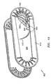
- FIGS. 8 and 9 are perspective views of embodiments of suture packages in accordance with the present invention.
- the suture packages 800 and 900, illustrated in FIGS. 8 and 9 , respectively, are similar to each other and to the suture package described above with reference to FIG. 1C , with certain differences.
- the most significant difference is the addition of partitions 815 in the embodiment illustrated in FIG. 8 .
- Partitions 815 connect each row of suture retaining area protrusions 840.
- partitions 815 instead of having individual suture retaining area protrusions 940, partitions 815 connect the suture retaining area protrusions 840 in a manner which defines a contiguous wall to further define suture retaining areas 830.
- Sutures 825 and 925 having needles 870 and 970 attached thereto are illustrated wound within suture retaining areas 830 and 930.
- the partitions 815 enhance the connection between the cover and base to prevent suture binding. Additionally, benefits associated with the injection molding process can be realized with embodiments having partitions.
- the suture prior to being placed within a suture package, the suture is typically attached to a needle to provide a needle-suture combination. That is, a needle 970 is fitted onto an end of the suture 945.
- a needle park assembly is provided within the central section of the suture-removal area 985 on a surface of cover 910.
- the needle park assembly includes a pair of fins 995 and a post 965.
- Post 965 has a circular cross-section and fins 995 are flexible.
- the characteristics of fins 995 and post 965 provide a three-point contact with a needle 970 and allow the needle park assembly to accommodate needles having different curvatures.
- cover 910 defines an opening 990 to provide unrestricted access for surgical personnel to the needle 970. More specifically, opening 990 provides surgical personnel with the ability to insert a needle holder past the surface of the cover. Surgical personnel can gain access to the needle and suture through the opening 970 in cover 910 by disengaging needle 970 from the needle park and then pulling the suture 945 from suture retaining area.
- an information label 1015 is attached to an upper surface of the cover 1010.
- the information label 1015 includes indicia 1025 which, at least in part, provides information regarding the contents of the suture package. It is preferred that the information label 1015 is attached to the cover 1010 via an adhesive around at least a portion of a perimeter of the label. When applying the adhesive, care should be exercised to keep the adhesive from coming into contact with the needle and/or suture.
- Information label 1015 is preferably formed of paper.
- a paper label is particularly useful as a moisture sink when bio-absorbable sutures are used.
- Information label 1015 illustrated in FIG. 11 does not completely cover the entire surface area of cover 1010. Thus, the surgical personnel will have ready access to needle 1070 as well as the ability to quickly remove information label 1015.
- the information label 1015 illustrated in FIG. 12 covers the entire surface area of cover 1010.
- the paper information label 1015 includes a plurality of perforations 1035 to define a tear line in a predetermined location.
- the predetermined location corresponds to a location above and substantially perpendicular to the needle 1070 (shown in phantom) which is parked on the upper surface of the cover 1010.
- the perforations 1035 guide the tear when the surgical personnel open the package and prevent the needle from tipping.
- suture-needle combination can be removed through an opening formed in the base. Therefore, the above description should not be construed as limiting, but merely as description by way of reference to example embodiments. Those skilled in the art will envision other modifications within the scope of the claims.
Landscapes
- Health & Medical Sciences (AREA)
- Surgery (AREA)
- Life Sciences & Earth Sciences (AREA)
- Biomedical Technology (AREA)
- Nuclear Medicine, Radiotherapy & Molecular Imaging (AREA)
- Engineering & Computer Science (AREA)
- Dentistry (AREA)
- Heart & Thoracic Surgery (AREA)
- Medical Informatics (AREA)
- Molecular Biology (AREA)
- Animal Behavior & Ethology (AREA)
- General Health & Medical Sciences (AREA)
- Public Health (AREA)
- Veterinary Medicine (AREA)
- Surgical Instruments (AREA)
Claims (21)
- Nähfadenpackung (100, 200, 300, 400, 500, 600, 800, 900, 1000), umfassend:eine Basis (5, 105, 205, 305, 405, 505);eine Abdeckung (10, 110, 210, 310, 610, 910, 1010) mit einem Umfang und eingerichtet, um benachbart zu der Basis platziert zu sein, um die Nähfadenpackung zu bilden;eine Außenwand (15, 115, 215, 315), die sich von der Basis erhebt und sich wie ein Oval um einen äußeren Umfang der Basis erstreckt, wobei die Außenwand eine vorbestimmte Höhe und einen oberen Rand (20, 120, 220) derart aufweist, dass der obere Rand in die Abdeckung an ihrem Umfang eingreift, wenn die Abdeckung benachbart zu der Basis angeordnet ist, um eine äußere Wand der Nähfadenpackung zu bilden;eine Nähfadenaufnahmefläche (30, 130, 230, 330, 430, 530, 630, 830, 930), die innerhalb der Packung zwischen der äußeren Wand und einer inneren Grenze definiert ist, die eingerichtet ist, der Form der Nähfadenaufnahmefläche zu folgen; gekennzeichnet durcheine Mehrzahl von Sätzen von Nähfadenaufnahmeflächen-Vorsprüngen (40, 140, 340, 440, 540, 640, 840, 940) mit einer Höhe, die im Wesentlichen gleich der Höhe der Außenwand ist, und die sich von einer unteren Oberfläche der Abdeckung erstrecken, wobei die Sätze radial von einer Mitte der Abdeckung zwischen der inneren Grenze und der Außenwand verschoben sind, um die Nähfadenaufnahmefläche (30, 130, 230, 330, 430, 530, 630, 830, 930) in zwei oder mehr separate Aufnahmeflächen aufzuteilen, um entsprechend zwei oder mehr Umläufe des Nähfadens (45, 145, 245, 445, 545, 645, 945) vorzusehen.
- Nähfadenpackung nach Anspruch 1 mit chirurgischem Nähfadenmaterial (45, 145, 245, 445, 545, 645, 945), das innerhalb zumindest einer der separaten Aufnahmeflächen gewickelt ist.
- Nähfadenpackung nach Anspruch 2, wobei eine Nadel (70, 170, 270, 370, 470, 570, 670, 870, 970, 1070) an einem Ende des Nähfadenmaterials angebracht ist und innerhalb eines zentralen Gebiets (85, 185, 355, 985) der Basis, wie durch die Nähfadenaufnahmefläche (30, 130, 230, 330, 430, 530, 630, 830, 930) definiert, derart positioniert ist, dass die Nadel in eine Nadelaufnahme (75, 175, 275, 475, 575, 675, 965, 995) eingreift, um die Nadel in einer festen Position zu halten.
- Nähfadenpackung nach Anspruch 3, wobei die Nadelaufnahme an einer oberen Oberfläche der Abdeckung angeordnet ist.
- Nähfadenpackung nach Anspruch 3, wobei die Nadelaufnahme an der oberen Oberfläche der Basis angeordnet ist.
- Nähfadenpackung nach einem der vorstehenden Ansprüche, wobei die innere Grenze, welche die Nähfadenaufnahmefläche innerhalb der Packung definiert, durch eine innere Wand (35, 135, 235, 335) definiert ist, die sich von einer unteren Oberfläche der Abdeckung erstreckt.
- Nähfadenpackung nach einem der vorstehenden Ansprüche und mit einem Nähfaden (45, 145, 245, 445, 545, 645, 945), der innerhalb der separaten Aufnahmeflächen der radial aufgeteilten Nähfadenaufnahmefläche (30, 130, 230, 330, 430, 530, 630, 830, 930), beginnend in der separaten Aufnahmefläche benachbart zu der äußeren Wand, gewickelt ist.
- Nähfadenpackung nach einem der vorstehenden Ansprüche, wobei die Abdeckung (10, 110, 210, 310, 610, 910, 1010) eine Umfangsdimension aufweist, die im Wesentlichen gleich einer Umfangsdimension der Basis (5, 105, 205, 305, 405, 505) ist.
- Nähfadenpackung nach einem vorstehenden Anspruch, ferner umfassend Pfosten (60, 160, 260), die an Enden der Vorsprünge (40, 140, 340, 440, 540, 640, 840, 940) ausgebildet sind, wobei die Pfosten bemessen und eingerichtet sind, um in Öffnungen (65, 165, 265) einzugreifen, die in der Basis (5, 105, 205, 305, 405, 505) ausgebildet sind, um die Abdeckung an der Basis zu befestigen.
- Nähfadenpackung nach Anspruch 9, wobei die Pfosten (60, 160, 260) an die Basis (5, 105, 205, 305, 405, 505) geschweißt sind, um die Abdeckung an der Basis zu befestigen.
- Nähfadenpackung nach einem der vorstehenden Ansprüche, wobei zumindest eine der Basis (5, 105, 205, 305, 405, 505) und Abdeckung (10, 110, 210, 310, 610, 910, 1010) durch Spritzgießen gebildet ist.
- Nähfadenpackung nach einem der Ansprüche 1 bis 9, wobei zumindest eine der Basis (5, 105, 205, 305, 405, 505) und Abdeckung (10, 110, 210, 310, 610, 910, 1010) durch Thermoformen gebildet ist.
- Nähfadenpackung nach einem der vorstehenden Ansprüche, wobei zumindest eine der Basis (5, 105, 205, 305, 405, 505) und Abdeckung (10, 110, 210, 310, 610, 910, 1010) aus einem thermoplastischen Harz gemacht ist.
- Nähfadenpackung nach Anspruch 13, wobei das thermoplastische Harz ein Polyolefin oder ein Polyester ist.
- Nähfadenpackung nach einem vorstehenden Anspruch, wobei die Nähfadenpackung eine Nadelaufnahme (75, 175, 275, 475, 575, 675) zum Halten einer Nadel in einer festen Position aufweist, welche Nadelaufnahme zumindest zwei Rippen (995) und einen Pfosten (965) aufweist.
- Nähfadenpackung nach Anspruch 15, wobei die Nadelaufnahme (75, 175, 275, 475, 575, 675) flexibel ist, um Nadeln (70, 170, 270, 370, 470, 570, 670, 870, 970, 1070) mit unterschiedlichen Krümmungen aufzunehmen.
- Nähfadenpackung nach einem der vorstehenden Ansprüche, wobei die Abdeckung (10, 110, 210, 310, 610, 910, 1010) eine Öffnung (90, 990) darin definiert, um Zugang zu einer Nadel (70, 170, 270, 370, 470, 570, 670, 870, 970, 1070) und Nähfaden (45, 145, 245, 445, 545, 645, 945), die innerhalb der Packung aufgenommen sind, zu schaffen.
- Nähfadenpackung nach einem der vorstehenden Ansprüche, ferner umfassend ein Informationsetikett (1015), das an einer oberen Oberfläche der Abdeckung (10, 110, 210, 310, 610, 910, 1010) angebracht ist.
- Nähfadenpackung nach Anspruch 18, wobei das Informationsetikett (1015) eine Mehrzahl von Perforationen (1035) enthält, um eine Risslinie zu definieren.
- Verfahren zum Bilden einer chirurgischen Nähfadenpackung, wobei das Verfahren die folgenden Schritte umfasst:Bilden eines Basiselements (5, 105, 205, 305, 405, 505) mit einer Außenwand (15, 115, 215, 315), die sich um eine vorbestimmte Höhe von einer oberen Oberfläche erhebt und sich wie ein Oval um einen Umfang des Basiselements erstreckt; gekennzeichnet durchBilden eines Abdeckungselements (10, 110, 210, 310, 610, 910, 1010) mit einer Mehrzahl von Sätzen von Nähfadenaufnahmevorsprüngen (40, 140, 340, 440, 540, 640, 840, 940) mit einer Höhe, die im Wesentlichen gleich der Höhe der Außenwand ist, und die sich von einer unteren Oberfläche des Abdeckungselements erstrecken, wobei die Mehrzahl von Sätzen von Nähfadenaufnahmevorsprüngen radial verschoben ist und sich von der unteren Oberfläche des Abdeckungselements erstreckt, um eine Nähfadenaufnahmefläche (30, 130, 230, 330, 430, 530, 630, 830, 930), die zwischen der Außenwand und einer inneren Grenze definiert ist, die eingerichtet ist, um der Form der Nahfadenaufnahmefläche zu folgen, in zwei oder mehr separate Aufnahmeflächen aufzuteilen, um entsprechend zwei oder mehr Umläufe eines chirurgischen Nähfadens vorzusehen;Wickeln eines chirurgischen Nähfadens (45, 145, 245, 445, 545, 645, 945) innerhalb zumindest einer der separaten Aufnahmeflächen (30, 130, 230, 330, 430, 530, 630, 830, 930), die an der unteren Oberfläche des Abdeckungselements gebildet sind; undBewegen des Abdeckungselements benachbart zu dem Basiselement, um eine abgeschlossene chirurgische Nähfadenpackung (100, 200, 300, 400, 500, 600, 800, 900, 1010) zu bilden.
- Verfahren nach Anspruch 20, wobei das Basiselement (5, 105, 205, 305, 405, 505) eine Mehrzahl von Öffnungen (65, 165, 265) darin definiert, wobei die Öffnungen bemessen und eingerichtet sind, um Enden (60, 160, 260) der Vorsprünge (40, 140, 340, 440, 540, 640, 840, 940) aufzunehmen, um das Abdeckungselement (10, 110, 210, 310, 610, 910, 1010) an dem Basiselement zu befestigen.
Priority Applications (1)
| Application Number | Priority Date | Filing Date | Title |
|---|---|---|---|
| EP09169705.2A EP2119401B1 (de) | 2003-07-18 | 2004-07-19 | Verpackung für chirurgisches Nahtmaterial |
Applications Claiming Priority (2)
| Application Number | Priority Date | Filing Date | Title |
|---|---|---|---|
| US48846403P | 2003-07-18 | 2003-07-18 | |
| US488464P | 2003-07-18 |
Related Child Applications (1)
| Application Number | Title | Priority Date | Filing Date |
|---|---|---|---|
| EP09169705.2A Division EP2119401B1 (de) | 2003-07-18 | 2004-07-19 | Verpackung für chirurgisches Nahtmaterial |
Publications (2)
| Publication Number | Publication Date |
|---|---|
| EP1498076A1 EP1498076A1 (de) | 2005-01-19 |
| EP1498076B1 true EP1498076B1 (de) | 2009-09-09 |
Family
ID=33477009
Family Applications (2)
| Application Number | Title | Priority Date | Filing Date |
|---|---|---|---|
| EP04016955A Expired - Lifetime EP1498076B1 (de) | 2003-07-18 | 2004-07-19 | Verpackung für chirurgisches Nahtmaterial |
| EP09169705.2A Expired - Lifetime EP2119401B1 (de) | 2003-07-18 | 2004-07-19 | Verpackung für chirurgisches Nahtmaterial |
Family Applications After (1)
| Application Number | Title | Priority Date | Filing Date |
|---|---|---|---|
| EP09169705.2A Expired - Lifetime EP2119401B1 (de) | 2003-07-18 | 2004-07-19 | Verpackung für chirurgisches Nahtmaterial |
Country Status (7)
| Country | Link |
|---|---|
| US (3) | US7520382B2 (de) |
| EP (2) | EP1498076B1 (de) |
| JP (2) | JP4666966B2 (de) |
| AU (1) | AU2004203328B2 (de) |
| CA (1) | CA2474842C (de) |
| DE (1) | DE602004023031D1 (de) |
| ES (1) | ES2332312T3 (de) |
Cited By (1)
| Publication number | Priority date | Publication date | Assignee | Title |
|---|---|---|---|---|
| US8746445B2 (en) | 2003-07-18 | 2014-06-10 | Covidien Lp | Suture packaging |
Families Citing this family (49)
| Publication number | Priority date | Publication date | Assignee | Title |
|---|---|---|---|---|
| EP2308391B1 (de) | 2001-06-14 | 2016-08-31 | Endoevolution, Llc | Gerät zur Anbringung chirurgischer Nähte mit Fadenmanagement |
| US7637369B2 (en) * | 2003-07-18 | 2009-12-29 | Tyco Healthcare Group Lp | Suture packaging |
| US7520382B2 (en) | 2003-07-18 | 2009-04-21 | Tyco Healthcare Group Lp | Suture packaging |
| US20120055828A1 (en) * | 2003-07-18 | 2012-03-08 | John Kennedy | Suture Packaging |
| US8123764B2 (en) | 2004-09-20 | 2012-02-28 | Endoevolution, Llc | Apparatus and method for minimally invasive suturing |
| US9775600B2 (en) | 2010-10-01 | 2017-10-03 | Endoevolution, Llc | Devices and methods for minimally invasive suturing |
| US7976555B2 (en) | 2008-07-17 | 2011-07-12 | Endoevolution, Llc | Apparatus and method for minimally invasive suturing |
| US7694489B2 (en) | 2005-03-11 | 2010-04-13 | Tyco Healthcare Group Lp | Suture winding device |
| JP4798703B2 (ja) | 2005-03-11 | 2011-10-19 | タイコ ヘルスケア グループ リミテッド パートナーシップ | 縫合糸巻き取りデバイスおよびその使用の方法 |
| CA2640148C (en) | 2006-01-27 | 2014-09-09 | Suturtek Incorporated | Apparatus and method for tissue closure |
| DE102006007263A1 (de) * | 2006-02-10 | 2007-08-16 | Karl Storz Gmbh & Co.Kg | Verpackung für ein medizinisches Ankerelement samt Faden |
| US8256613B2 (en) * | 2008-04-07 | 2012-09-04 | Tyco Healthcare Group Lp | Suture packaging for barbed sutures |
| US7891485B2 (en) * | 2008-04-11 | 2011-02-22 | Tyco Healthcare Group Lp | Suture retainer with rib members |
| DE102008022666A1 (de) * | 2008-05-07 | 2009-12-03 | Endox Feinwerktechnik Gmbh | Drahtdipenser zur Aufnahme eines elastisch verformbaren Drahtes |
| US9622743B2 (en) | 2008-10-02 | 2017-04-18 | Covidien Lp | Suture packaging |
| US8292067B2 (en) * | 2009-06-09 | 2012-10-23 | Tyco Healthcare Group Lp | Knotless endostitch package |
| USD632957S1 (en) | 2009-08-20 | 2011-02-22 | Tyco Healthcare Group Lp | Suture package |
| USD630325S1 (en) | 2009-08-20 | 2011-01-04 | Tyco Healthcare Group Lp | Suture package |
| US8196739B2 (en) * | 2009-08-20 | 2012-06-12 | Tyco Healthcare Group Lp | Endostitch packages |
| US8307978B2 (en) | 2010-03-02 | 2012-11-13 | Covidien Lp | Knotless endostitch package |
| US8573391B2 (en) * | 2010-03-08 | 2013-11-05 | Ethicon, Inc. | Suture packages providing unconstrained dispensing of sutures and methods therefor |
| US20140083478A1 (en) * | 2011-04-19 | 2014-03-27 | Hokkaido Tokushushiryou Kabushikikaisha | Combustion Device, Combustion Method, and Electric Power-Generating Device and Electric Power-Generating Method Using Same |
| US10245025B2 (en) | 2012-04-06 | 2019-04-02 | Ethicon, Inc. | Packaged antimicrobial medical device having improved shelf life and method of preparing same |
| WO2013165942A1 (en) | 2012-05-01 | 2013-11-07 | Brigham And Women's Hospital, Inc. | Suturing device for laparoscopic procedures |
| US9486209B2 (en) | 2012-12-13 | 2016-11-08 | Ethicon Endo-Surgery, Llc | Transmission for driving circular needle |
| US9125645B1 (en) | 2013-03-11 | 2015-09-08 | Ethicon Endo-Surgery, Inc. | Reciprocating needle drive without cables |
| US9375212B2 (en) | 2014-06-06 | 2016-06-28 | Ethicon Endo-Surgery, Llc | Circular needle applier with cleats |
| US9788830B2 (en) | 2014-06-06 | 2017-10-17 | Ethicon Llc | Needle cartridge with cage |
| USD771811S1 (en) | 2013-03-15 | 2016-11-15 | Ethicon Endo-Surgery, Llc | Suture tray |
| DE102013007721A1 (de) * | 2013-05-04 | 2014-11-06 | Catgut Gmbh | Abgabeverpackung für ein chirurgisches Nahtmaterial und Verfahren zum Verpacken desselben |
| CN103690209B (zh) * | 2014-01-08 | 2015-06-24 | 薛新霞 | 一种医用缝合线盛放装置 |
| US9474522B2 (en) | 2014-06-06 | 2016-10-25 | Ethicon Endo-Surgery, Llc | Jawed receiver for needle cartridge |
| USD745146S1 (en) | 2014-06-06 | 2015-12-08 | Ethicon Endo-Surgery, Inc. | Surgical suturing device |
| USD744648S1 (en) * | 2014-07-08 | 2015-12-01 | Surgical Specialties Corporation | Suture dispensing card |
| WO2016014579A1 (en) * | 2014-07-21 | 2016-01-28 | Surgical Specialties Corporation | Suture carrier devices, systems, and methods of using same |
| US10022120B2 (en) | 2015-05-26 | 2018-07-17 | Ethicon Llc | Surgical needle with recessed features |
| US9776783B2 (en) | 2015-06-04 | 2017-10-03 | Covidien Lp | Foldable sleeve for surgical instrument |
| USD800306S1 (en) | 2015-12-10 | 2017-10-17 | Ethicon Llc | Surgical suturing device |
| WO2018119459A1 (en) | 2016-12-23 | 2018-06-28 | Brigham And Women's Hospital, Inc. | Systems and methods for suturing tissue |
| USD865964S1 (en) | 2017-01-05 | 2019-11-05 | Ethicon Llc | Handle for electrosurgical instrument |
| US20180235625A1 (en) * | 2017-02-17 | 2018-08-23 | Ethicon Llc | End effector with adjunct materials |
| US20180242967A1 (en) | 2017-02-26 | 2018-08-30 | Endoevolution, Llc | Apparatus and method for minimally invasive suturing |
| US10292698B2 (en) | 2017-07-27 | 2019-05-21 | Endoevolution, Llc | Apparatus and method for minimally invasive suturing |
| KR101925744B1 (ko) * | 2018-02-19 | 2018-12-06 | 이길수 | 의료용 봉합사 패키지 |
| USD895112S1 (en) | 2018-11-15 | 2020-09-01 | Ethicon Llc | Laparoscopic bipolar electrosurgical device |
| EP3944733B1 (de) * | 2019-03-13 | 2024-04-17 | Seyed Hassan Atyabi | Nahtverpackung |
| US12402877B2 (en) | 2021-06-07 | 2025-09-02 | Intuitive Surgical Operations, Inc. | Needle loader devices and related systems and methods |
| US20220387023A1 (en) * | 2021-06-08 | 2022-12-08 | George Swope MUNDAY | Apparatus for closing a surgical site |
| CN113440191A (zh) * | 2021-07-23 | 2021-09-28 | 李志永 | 一种医用带针可吸收或非可吸收缝合线收纳装置 |
Family Cites Families (113)
| Publication number | Priority date | Publication date | Assignee | Title |
|---|---|---|---|---|
| US523683A (en) * | 1894-07-31 | George a | ||
| US2348688A (en) | 1942-11-30 | 1944-05-09 | Marathon Paper Mills Co | Heat-sealable label |
| US3127992A (en) * | 1962-01-19 | 1964-04-07 | Cyrus F Horine | Suture package |
| FR1456887A (fr) | 1965-09-16 | 1966-10-28 | Robert & Carriere Lab | Perfectionnements aux dispositifs d'emballage pour ligatures |
| US3580791A (en) | 1968-06-19 | 1971-05-25 | American Greetings Corp | Device for applying a band of thermosetting material onto a label and for sealing the label onto an article |
| US3706174A (en) | 1971-03-03 | 1972-12-19 | Grace W R & Co | Packaging machine and method of forming packages |
| US3815315A (en) * | 1971-04-29 | 1974-06-11 | American Cyanamid Co | Ethylene oxide sterilization of moisture sensitive surgical elements |
| US3749238A (en) | 1971-09-23 | 1973-07-31 | Cenco Medical Health Supply Co | Suture dispenser package and method of making |
| BE795434A (fr) * | 1972-02-14 | 1973-08-14 | Ethicon Inc | Trousse de suture |
| US3876068A (en) | 1973-08-08 | 1975-04-08 | American Cyanamid Co | Suture reel-label package |
| US4097325A (en) | 1973-10-15 | 1978-06-27 | A-T-O Inc. | Label-applying apparatus for applying thermoplastic labels |
| US3939969A (en) | 1974-07-24 | 1976-02-24 | Ethicon, Inc. | Suture package |
| US3988195A (en) | 1976-01-27 | 1976-10-26 | National Distillers And Chemical Corporation | Machine for applying a semipermeable patch on a plastic bag |
| US4069912A (en) | 1977-03-15 | 1978-01-24 | American Cyanamid Company | Suture package |
| US4243140A (en) | 1979-07-13 | 1981-01-06 | Anchor Products Company | Surgical needle and sharps holding container |
| US4343140A (en) * | 1981-01-19 | 1982-08-10 | Claas Ohg | Sugar-cane harvester |
| US4424898A (en) * | 1982-04-08 | 1984-01-10 | Ethicon, Inc. | Needle and suture holder and package |
| US4699271A (en) * | 1984-06-14 | 1987-10-13 | Lincoln Jay P | Plastic dispensing pack for surgical sutures |
| US4582196A (en) * | 1984-11-19 | 1986-04-15 | Hughson Sharon J | Yarn dispenser |
| US4625498A (en) | 1985-03-25 | 1986-12-02 | Sealright Co., Inc. | Apparatus for applying recessed membrane seals to containers |
| US4696404A (en) | 1986-08-27 | 1987-09-29 | Corella Arthur P | Heat sealed package with perforated compartment seal |
| US6260699B1 (en) * | 1987-08-26 | 2001-07-17 | United States Surgical Corporation | Packaged synthetic absorbable surgical elements |
| US5462162A (en) * | 1987-08-26 | 1995-10-31 | United States Surgical Corporation | Packaged synthetic absorbable surgical elements |
| US5222978A (en) * | 1987-08-26 | 1993-06-29 | United States Surgical Corporation | Packaged synthetic absorbable surgical elements |
| US4840270A (en) | 1987-12-21 | 1989-06-20 | Nice-Pak Products, Inc. | Re-sealable label flap |
| US4832774A (en) | 1988-05-06 | 1989-05-23 | Owens-Illinois Glass Container Inc. | Method and apparatus for applying wrap-around labels to containers |
| US4961498A (en) * | 1988-08-24 | 1990-10-09 | Ethicon, Inc. | Oval wrap suture package |
| US5099994A (en) * | 1988-08-24 | 1992-03-31 | Ethicon, Inc. | Oval wrap suture package |
| US5179818A (en) * | 1988-08-24 | 1993-01-19 | Ethicon, Inc. | Oval wrap suture package |
| US5266377A (en) | 1989-03-17 | 1993-11-30 | Yoshino Kogyosho Co., Ltd. | Label and method for in-mold molding using a label thereof |
| US5246104A (en) * | 1989-08-01 | 1993-09-21 | United States Surgical Corporation | Molded suture retainer |
| US5154283A (en) * | 1990-08-13 | 1992-10-13 | United States Surgical Corporation | Molded suture retainer |
| US5359831A (en) * | 1989-08-01 | 1994-11-01 | United States Surgical Corporation | Molded suture retainer |
| US5165217A (en) * | 1989-09-12 | 1992-11-24 | Ethicon, Inc. | One piece channel suture packages |
| US4967902A (en) | 1989-09-12 | 1990-11-06 | Ethicon, Inc. | One piece channel suture packages |
| US5236083A (en) | 1989-09-12 | 1993-08-17 | Ethicon, Inc. | One piece channel suture packages |
| US5056658A (en) * | 1989-09-12 | 1991-10-15 | Ethicon, Inc. | One piece channel suture packages |
| US4980014A (en) | 1989-12-21 | 1990-12-25 | Owens-Brockway Glass Container Inc. | Apparatus for applying wrap-around labels to containers |
| US5137596A (en) * | 1990-01-12 | 1992-08-11 | B & H Manufacturing Company, Inc. | Apparatus for heat sealing labels on containers |
| US5182053A (en) * | 1990-03-02 | 1993-01-26 | Optical Radiation Corporation | Process for forming intraocular lenses having haptics with high fracture toughness |
| US5121836A (en) * | 1990-05-25 | 1992-06-16 | United States Surgical Corporation | Retainer for combined surgical suture-needle device |
| US5197597A (en) * | 1990-06-05 | 1993-03-30 | United States Surgical Corporation | Suture retainer |
| US5261210A (en) * | 1990-08-13 | 1993-11-16 | United States Surgical Corporation | Molded suture retainer |
| US5220769A (en) | 1991-01-04 | 1993-06-22 | United States Surgical Corporation | Method for packaging surgical elements |
| US5052551A (en) * | 1991-01-31 | 1991-10-01 | Ethicon, Inc. | Oval wrap suture package with unequal end radii |
| US5131533A (en) * | 1991-08-28 | 1992-07-21 | Ethicon, Inc. | Needle park |
| US5192483A (en) * | 1991-12-02 | 1993-03-09 | W. L. Gore & Associates, Inc. | Method of thermoforming a sheet around a suture needle to form a holder |
| WO1993010713A1 (en) * | 1991-12-02 | 1993-06-10 | W.L. Gore & Associates, Inc. | A needle holder for a suture package |
| CA2080978A1 (en) | 1992-01-02 | 1993-07-03 | Hans-Jurgen F. Sinn | Retainer for a combined surgical needle shield with a needle tip stop feature |
| US5249671A (en) * | 1992-02-07 | 1993-10-05 | United States Surgical Corporation | Package and method of loading for resilient surgical sutures |
| US5249673A (en) * | 1992-02-07 | 1993-10-05 | United States Surgical Corporation | Package and method of loading for resilient surgical sutures |
| US5228565A (en) * | 1992-02-26 | 1993-07-20 | United States Surgical Corporation | Package and method of loading for resilient surgical sutures |
| US5180053A (en) | 1992-02-28 | 1993-01-19 | Ethicon, Inc. | Cantilevered needle park |
| US5213210A (en) * | 1992-02-28 | 1993-05-25 | Ethicon, Inc. | Easy-loading suture package |
| CA2092937A1 (en) | 1992-04-01 | 1993-10-02 | Marvin Alpern | Oval wrap suture package with rotary wheel |
| US5271495A (en) * | 1992-04-01 | 1993-12-21 | Ethicon, Inc. | Oval wrap suture package with rotary wheel |
| US5263585A (en) * | 1992-05-07 | 1993-11-23 | Myriadlase, Inc. | Package for an elongated flexible fiber |
| US5246109A (en) | 1992-05-22 | 1993-09-21 | Biomedical Sensors, Ltd. | Package for an active medical device |
| US5230424A (en) * | 1992-06-19 | 1993-07-27 | Ethicon, Inc. | Multi-strand suture package and cover-latching element |
| CA2097664C (en) | 1992-07-09 | 1999-05-04 | David L. Brown | Package for surgical devices |
| US5350060A (en) * | 1993-01-15 | 1994-09-27 | Ethicon, Inc. | Procedure kit and package |
| US5284240A (en) * | 1993-01-22 | 1994-02-08 | Ethicon, Inc. | No touch suture package |
| CA2129277A1 (en) | 1993-09-13 | 1995-03-14 | Christopher Scanlon | Retainer package for resilient filaments |
| US5503266A (en) * | 1993-10-15 | 1996-04-02 | United States Surgical Corporation | Molded suture retainer with needle park |
| AU1624695A (en) * | 1994-04-04 | 1995-10-12 | Ethicon Inc. | Suture dispenser |
| US5649410A (en) | 1994-06-10 | 1997-07-22 | Johnson & Johnson Vision Products, Inc. | Post-hydration method and apparatus for transporting, inspecting and packaging contact lenses |
| US5575382A (en) * | 1994-12-22 | 1996-11-19 | Ethicon, Inc. | Rotary self-winding two-piece ligature package |
| JP2852128B2 (ja) | 1995-02-10 | 1999-01-27 | メルク エンド カンパニー インコーポレーテッド | ある種のアザシクロヘキサペプチドの製造方法 |
| DE69605694T2 (de) | 1995-02-21 | 2000-06-08 | Ethicon, Inc. | Nahtmaterialverpackung |
| US5755079A (en) | 1995-03-08 | 1998-05-26 | Westvaco Corporation | Composite package structure for containing articles and method for producing thereof |
| US5675961A (en) * | 1995-06-06 | 1997-10-14 | Ethicon, Inc. | Suture dispenser |
| US5669490A (en) * | 1995-06-07 | 1997-09-23 | United States Surgical Corporation | Suture retainer |
| US5628395A (en) * | 1995-06-23 | 1997-05-13 | Ethicon, Inc. | Suture tray package having grooved winding surface |
| US5613349A (en) | 1995-08-28 | 1997-03-25 | Elr, Inc. | Method of making product packages |
| US5833055A (en) * | 1996-03-29 | 1998-11-10 | Ethicon, Inc. | Surgical suture package with peelable foil heat seal |
| US5623810A (en) | 1996-03-29 | 1997-04-29 | Ethicon, Inc. | Method for making sterile suture packages |
| US5733293A (en) * | 1996-05-08 | 1998-03-31 | United States Surgical Corporation | Disposable loading unit for a vascular suturing instrument |
| US5695138A (en) * | 1996-09-03 | 1997-12-09 | Ethicon, Inc. | Winding fixture for surgical suture package |
| US5755081A (en) | 1997-01-31 | 1998-05-26 | W. R. Grace & Co.-Conn. | Heat-sealable, multilayer film containing therein a colorant and method for making a package with such film |
| BR9703513A (pt) * | 1997-06-10 | 1999-01-05 | Johnson & Johnson Produtos Pro | Distribuidor de suturas cirúrgicas e processo de enrolamento de sutura cirúrgica |
| DE19744543A1 (de) | 1997-10-09 | 1999-04-22 | Braun Surgical S A B | Nahtmaterialspender |
| US5868244A (en) | 1997-12-01 | 1999-02-09 | Ethicon, Inc. | Microbial barrier vented package for sterile medical devices and method of packaging |
| US5887706A (en) * | 1997-12-05 | 1999-03-30 | Ethicon, Inc. | Fenestrated suture package |
| US5906273A (en) * | 1997-12-05 | 1999-05-25 | Ethicon, Inc. | Armed suture package with universal dispensing capability |
| US6076659A (en) * | 1998-01-19 | 2000-06-20 | Ethicon, Inc. | Packaging for surgical suture material |
| US5983601A (en) | 1998-02-06 | 1999-11-16 | Ethicon, Inc. | Machine for the automated packaging of needles and attached sutures |
| GB2334503B (en) * | 1998-02-27 | 2002-04-24 | Ethicon Inc | Suture container |
| US6016905A (en) * | 1998-03-06 | 2000-01-25 | United States Surgical Corporation | Surgical suture retainer package |
| US6138440A (en) * | 1998-03-06 | 2000-10-31 | United States Surgical Corporation | Surgical suture retainer package |
| US5918733A (en) * | 1998-04-08 | 1999-07-06 | Ethicon, Inc. | Ligating reel package |
| KR100371828B1 (ko) * | 1998-08-04 | 2003-02-12 | 다이켄카가쿠 코교 가부시키가이샤 | 퀴크 히트 로울러 |
| US6047815A (en) * | 1998-08-31 | 2000-04-11 | Ethicon, Inc. | Package for sutures |
| US6021625A (en) | 1998-11-24 | 2000-02-08 | Ethicon, Inc. | Process for microbial barrier vent to a foil package |
| DE19855577B4 (de) * | 1998-12-02 | 2004-07-15 | Ethicon Gmbh | Verpackung für chirurgisches Nahtmaterial |
| WO2000053103A1 (en) | 1999-03-11 | 2000-09-14 | Ethicon, Inc. | Improved needle park and method of use |
| US6481568B1 (en) * | 1999-03-29 | 2002-11-19 | Ethicon, Inc. | Labyrinth package for sutures |
| US6135272A (en) * | 1999-10-22 | 2000-10-24 | Ethicon, Inc. | Package for sutures |
| DE19959263B4 (de) * | 1999-12-03 | 2005-03-17 | Ethicon Gmbh | Verpackung für chirurgisches Nahtmaterial |
| KR100365692B1 (ko) * | 2000-02-24 | 2002-12-26 | 삼성전자 주식회사 | 토너 화상 정착을 위한 직접 가열 롤러 및 그 제조 방법 |
| JP2002082559A (ja) * | 2000-06-22 | 2002-03-22 | Ricoh Co Ltd | 加熱ローラ及び加熱ローラの製造方法及び加熱装置及び定着装置及び画像形成装置 |
| US6625955B2 (en) | 2000-06-28 | 2003-09-30 | Aylward Enterprises, Inc. | Methods for forming product package with recloseable locking mechanism |
| US6394269B1 (en) * | 2000-09-29 | 2002-05-28 | Ethicon, Inc. | Needle package with point guards |
| US6484569B1 (en) * | 2000-10-27 | 2002-11-26 | Waters Investments Limited | Tube-in-tube thermal exchanger for liquid chromatography systems |
| US6463719B2 (en) | 2000-12-13 | 2002-10-15 | Ethicon | Suture winding machine, suture tray package, and method of winding sutures |
| CA2438474C (en) * | 2001-02-21 | 2008-01-15 | Dalter Alimentari S.P.A. | Dispenser for granular or powdered food products, for example grated cheese and similar loose food products, and corresponding manufacturing process |
| US6644469B2 (en) | 2001-07-11 | 2003-11-11 | Ethicon, Inc. | Large needle oval wound plastic suture package |
| US20030192893A1 (en) | 2002-04-15 | 2003-10-16 | Silvio Weder | Product package having multi-layer labeling cover assembly |
| JP3901592B2 (ja) * | 2002-06-24 | 2007-04-04 | 株式会社フジキカイ | 再封性包装袋と製袋充填機 |
| US6804937B2 (en) * | 2003-03-13 | 2004-10-19 | Ethicon, Inc. | Package winding machine |
| US7637369B2 (en) * | 2003-07-18 | 2009-12-29 | Tyco Healthcare Group Lp | Suture packaging |
| US7520382B2 (en) | 2003-07-18 | 2009-04-21 | Tyco Healthcare Group Lp | Suture packaging |
| US6915623B2 (en) | 2003-08-14 | 2005-07-12 | Ethicon, Inc. | Method for assembling a package for sutures |
| US20050125036A1 (en) * | 2003-08-14 | 2005-06-09 | Mark Roby | Heterogeneous yarns for surgical articles |
-
2004
- 2004-07-15 US US10/891,604 patent/US7520382B2/en not_active Expired - Lifetime
- 2004-07-16 AU AU2004203328A patent/AU2004203328B2/en not_active Ceased
- 2004-07-16 CA CA2474842A patent/CA2474842C/en not_active Expired - Fee Related
- 2004-07-16 JP JP2004210857A patent/JP4666966B2/ja not_active Expired - Fee Related
- 2004-07-19 EP EP04016955A patent/EP1498076B1/de not_active Expired - Lifetime
- 2004-07-19 ES ES04016955T patent/ES2332312T3/es not_active Expired - Lifetime
- 2004-07-19 EP EP09169705.2A patent/EP2119401B1/de not_active Expired - Lifetime
- 2004-07-19 DE DE602004023031T patent/DE602004023031D1/de not_active Expired - Lifetime
-
2009
- 2009-03-13 US US12/404,013 patent/US20090205987A1/en not_active Abandoned
- 2009-12-17 US US12/640,477 patent/US8136656B2/en not_active Expired - Lifetime
-
2010
- 2010-06-11 JP JP2010134586A patent/JP2010264252A/ja active Pending
Cited By (1)
| Publication number | Priority date | Publication date | Assignee | Title |
|---|---|---|---|---|
| US8746445B2 (en) | 2003-07-18 | 2014-06-10 | Covidien Lp | Suture packaging |
Also Published As
| Publication number | Publication date |
|---|---|
| CA2474842A1 (en) | 2005-01-18 |
| ES2332312T3 (es) | 2010-02-02 |
| EP2119401B1 (de) | 2017-07-05 |
| JP2005040607A (ja) | 2005-02-17 |
| US20100089780A1 (en) | 2010-04-15 |
| AU2004203328B2 (en) | 2010-08-26 |
| US20090205987A1 (en) | 2009-08-20 |
| DE602004023031D1 (de) | 2009-10-22 |
| EP2119401A1 (de) | 2009-11-18 |
| CA2474842C (en) | 2011-06-21 |
| EP1498076A1 (de) | 2005-01-19 |
| US7520382B2 (en) | 2009-04-21 |
| US20050035007A1 (en) | 2005-02-17 |
| JP2010264252A (ja) | 2010-11-25 |
| JP4666966B2 (ja) | 2011-04-06 |
| US8136656B2 (en) | 2012-03-20 |
| AU2004203328A1 (en) | 2005-02-03 |
Similar Documents
| Publication | Publication Date | Title |
|---|---|---|
| EP2119401B1 (de) | Verpackung für chirurgisches Nahtmaterial | |
| EP1842494B1 (de) | Verpackung für chirurgisches Nahtmaterial | |
| US8746445B2 (en) | Suture packaging | |
| US20120055828A1 (en) | Suture Packaging | |
| EP2113205B1 (de) | Nahtverpackung für Nahtmaterial mit Widerhaken | |
| JP3753795B2 (ja) | 巻溝を有する縫糸パッケージ |
Legal Events
| Date | Code | Title | Description |
|---|---|---|---|
| PUAI | Public reference made under article 153(3) epc to a published international application that has entered the european phase |
Free format text: ORIGINAL CODE: 0009012 |
|
| AK | Designated contracting states |
Kind code of ref document: A1 Designated state(s): AT BE BG CH CY CZ DE DK EE ES FI FR GB GR HU IE IT LI LU MC NL PL PT RO SE SI SK TR |
|
| AX | Request for extension of the european patent |
Extension state: AL HR LT LV MK |
|
| 17P | Request for examination filed |
Effective date: 20050317 |
|
| AKX | Designation fees paid |
Designated state(s): DE ES FR GB IT |
|
| 17Q | First examination report despatched |
Effective date: 20071116 |
|
| GRAP | Despatch of communication of intention to grant a patent |
Free format text: ORIGINAL CODE: EPIDOSNIGR1 |
|
| GRAS | Grant fee paid |
Free format text: ORIGINAL CODE: EPIDOSNIGR3 |
|
| GRAA | (expected) grant |
Free format text: ORIGINAL CODE: 0009210 |
|
| AK | Designated contracting states |
Kind code of ref document: B1 Designated state(s): DE ES FR GB IT |
|
| REG | Reference to a national code |
Ref country code: GB Ref legal event code: FG4D |
|
| REF | Corresponds to: |
Ref document number: 602004023031 Country of ref document: DE Date of ref document: 20091022 Kind code of ref document: P |
|
| REG | Reference to a national code |
Ref country code: ES Ref legal event code: FG2A Ref document number: 2332312 Country of ref document: ES Kind code of ref document: T3 |
|
| PLBE | No opposition filed within time limit |
Free format text: ORIGINAL CODE: 0009261 |
|
| STAA | Information on the status of an ep patent application or granted ep patent |
Free format text: STATUS: NO OPPOSITION FILED WITHIN TIME LIMIT |
|
| 26N | No opposition filed |
Effective date: 20100610 |
|
| PGFP | Annual fee paid to national office [announced via postgrant information from national office to epo] |
Ref country code: ES Payment date: 20110726 Year of fee payment: 8 |
|
| PGFP | Annual fee paid to national office [announced via postgrant information from national office to epo] |
Ref country code: IT Payment date: 20110722 Year of fee payment: 8 |
|
| PG25 | Lapsed in a contracting state [announced via postgrant information from national office to epo] |
Ref country code: IT Free format text: LAPSE BECAUSE OF NON-PAYMENT OF DUE FEES Effective date: 20120719 |
|
| REG | Reference to a national code |
Ref country code: ES Ref legal event code: FD2A Effective date: 20131021 |
|
| PG25 | Lapsed in a contracting state [announced via postgrant information from national office to epo] |
Ref country code: ES Free format text: LAPSE BECAUSE OF NON-PAYMENT OF DUE FEES Effective date: 20120720 |
|
| REG | Reference to a national code |
Ref country code: FR Ref legal event code: PLFP Year of fee payment: 13 |
|
| REG | Reference to a national code |
Ref country code: FR Ref legal event code: PLFP Year of fee payment: 14 |
|
| REG | Reference to a national code |
Ref country code: FR Ref legal event code: PLFP Year of fee payment: 15 |
|
| PGFP | Annual fee paid to national office [announced via postgrant information from national office to epo] |
Ref country code: GB Payment date: 20210623 Year of fee payment: 18 |
|
| GBPC | Gb: european patent ceased through non-payment of renewal fee |
Effective date: 20220719 |
|
| PG25 | Lapsed in a contracting state [announced via postgrant information from national office to epo] |
Ref country code: GB Free format text: LAPSE BECAUSE OF NON-PAYMENT OF DUE FEES Effective date: 20220719 |
|
| PGFP | Annual fee paid to national office [announced via postgrant information from national office to epo] |
Ref country code: FR Payment date: 20230621 Year of fee payment: 20 |
|
| PGFP | Annual fee paid to national office [announced via postgrant information from national office to epo] |
Ref country code: DE Payment date: 20230620 Year of fee payment: 20 |
|
| REG | Reference to a national code |
Ref country code: DE Ref legal event code: R071 Ref document number: 602004023031 Country of ref document: DE |