EP1498011B1 - Oxygen substituted barium thioaluminate phosphor materials - Google Patents
Oxygen substituted barium thioaluminate phosphor materials Download PDFInfo
- Publication number
- EP1498011B1 EP1498011B1 EP03714586A EP03714586A EP1498011B1 EP 1498011 B1 EP1498011 B1 EP 1498011B1 EP 03714586 A EP03714586 A EP 03714586A EP 03714586 A EP03714586 A EP 03714586A EP 1498011 B1 EP1498011 B1 EP 1498011B1
- Authority
- EP
- European Patent Office
- Prior art keywords
- phosphor
- oxygen
- film
- temperature
- barium
- Prior art date
- Legal status (The legal status is an assumption and is not a legal conclusion. Google has not performed a legal analysis and makes no representation as to the accuracy of the status listed.)
- Expired - Lifetime
Links
Images


Classifications
-
- C—CHEMISTRY; METALLURGY
- C09—DYES; PAINTS; POLISHES; NATURAL RESINS; ADHESIVES; COMPOSITIONS NOT OTHERWISE PROVIDED FOR; APPLICATIONS OF MATERIALS NOT OTHERWISE PROVIDED FOR
- C09K—MATERIALS FOR MISCELLANEOUS APPLICATIONS, NOT PROVIDED FOR ELSEWHERE
- C09K11/00—Luminescent materials, e.g. electroluminescent or chemiluminescent
- C09K11/08—Luminescent materials, e.g. electroluminescent or chemiluminescent containing inorganic luminescent materials
- C09K11/77—Luminescent materials, e.g. electroluminescent or chemiluminescent containing inorganic luminescent materials containing rare earth metals
- C09K11/7706—Aluminates
-
- C—CHEMISTRY; METALLURGY
- C09—DYES; PAINTS; POLISHES; NATURAL RESINS; ADHESIVES; COMPOSITIONS NOT OTHERWISE PROVIDED FOR; APPLICATIONS OF MATERIALS NOT OTHERWISE PROVIDED FOR
- C09K—MATERIALS FOR MISCELLANEOUS APPLICATIONS, NOT PROVIDED FOR ELSEWHERE
- C09K11/00—Luminescent materials, e.g. electroluminescent or chemiluminescent
- C09K11/08—Luminescent materials, e.g. electroluminescent or chemiluminescent containing inorganic luminescent materials
- C09K11/56—Luminescent materials, e.g. electroluminescent or chemiluminescent containing inorganic luminescent materials containing sulfur
-
- C—CHEMISTRY; METALLURGY
- C09—DYES; PAINTS; POLISHES; NATURAL RESINS; ADHESIVES; COMPOSITIONS NOT OTHERWISE PROVIDED FOR; APPLICATIONS OF MATERIALS NOT OTHERWISE PROVIDED FOR
- C09K—MATERIALS FOR MISCELLANEOUS APPLICATIONS, NOT PROVIDED FOR ELSEWHERE
- C09K11/00—Luminescent materials, e.g. electroluminescent or chemiluminescent
- C09K11/08—Luminescent materials, e.g. electroluminescent or chemiluminescent containing inorganic luminescent materials
- C09K11/77—Luminescent materials, e.g. electroluminescent or chemiluminescent containing inorganic luminescent materials containing rare earth metals
- C09K11/7701—Chalogenides
- C09K11/7703—Chalogenides with alkaline earth metals
-
- C—CHEMISTRY; METALLURGY
- C09—DYES; PAINTS; POLISHES; NATURAL RESINS; ADHESIVES; COMPOSITIONS NOT OTHERWISE PROVIDED FOR; APPLICATIONS OF MATERIALS NOT OTHERWISE PROVIDED FOR
- C09K—MATERIALS FOR MISCELLANEOUS APPLICATIONS, NOT PROVIDED FOR ELSEWHERE
- C09K11/00—Luminescent materials, e.g. electroluminescent or chemiluminescent
- C09K11/08—Luminescent materials, e.g. electroluminescent or chemiluminescent containing inorganic luminescent materials
- C09K11/77—Luminescent materials, e.g. electroluminescent or chemiluminescent containing inorganic luminescent materials containing rare earth metals
- C09K11/7728—Luminescent materials, e.g. electroluminescent or chemiluminescent containing inorganic luminescent materials containing rare earth metals containing europium
- C09K11/7729—Chalcogenides
- C09K11/7731—Chalcogenides with alkaline earth metals
-
- C—CHEMISTRY; METALLURGY
- C09—DYES; PAINTS; POLISHES; NATURAL RESINS; ADHESIVES; COMPOSITIONS NOT OTHERWISE PROVIDED FOR; APPLICATIONS OF MATERIALS NOT OTHERWISE PROVIDED FOR
- C09K—MATERIALS FOR MISCELLANEOUS APPLICATIONS, NOT PROVIDED FOR ELSEWHERE
- C09K11/00—Luminescent materials, e.g. electroluminescent or chemiluminescent
- C09K11/08—Luminescent materials, e.g. electroluminescent or chemiluminescent containing inorganic luminescent materials
- C09K11/77—Luminescent materials, e.g. electroluminescent or chemiluminescent containing inorganic luminescent materials containing rare earth metals
- C09K11/7728—Luminescent materials, e.g. electroluminescent or chemiluminescent containing inorganic luminescent materials containing rare earth metals containing europium
- C09K11/7734—Aluminates
-
- H—ELECTRICITY
- H05—ELECTRIC TECHNIQUES NOT OTHERWISE PROVIDED FOR
- H05B—ELECTRIC HEATING; ELECTRIC LIGHT SOURCES NOT OTHERWISE PROVIDED FOR; CIRCUIT ARRANGEMENTS FOR ELECTRIC LIGHT SOURCES, IN GENERAL
- H05B33/00—Electroluminescent light sources
- H05B33/10—Apparatus or processes specially adapted to the manufacture of electroluminescent light sources
-
- H—ELECTRICITY
- H05—ELECTRIC TECHNIQUES NOT OTHERWISE PROVIDED FOR
- H05B—ELECTRIC HEATING; ELECTRIC LIGHT SOURCES NOT OTHERWISE PROVIDED FOR; CIRCUIT ARRANGEMENTS FOR ELECTRIC LIGHT SOURCES, IN GENERAL
- H05B33/00—Electroluminescent light sources
- H05B33/12—Light sources with substantially two-dimensional [2D] radiating surfaces
- H05B33/14—Light sources with substantially two-dimensional [2D] radiating surfaces characterised by the chemical or physical composition or the arrangement of the electroluminescent material, or by the simultaneous addition of the electroluminescent material in or onto the light source
-
- H—ELECTRICITY
- H05—ELECTRIC TECHNIQUES NOT OTHERWISE PROVIDED FOR
- H05B—ELECTRIC HEATING; ELECTRIC LIGHT SOURCES NOT OTHERWISE PROVIDED FOR; CIRCUIT ARRANGEMENTS FOR ELECTRIC LIGHT SOURCES, IN GENERAL
- H05B33/00—Electroluminescent light sources
- H05B33/12—Light sources with substantially two-dimensional [2D] radiating surfaces
- H05B33/22—Light sources with substantially two-dimensional [2D] radiating surfaces characterised by the chemical or physical composition or the arrangement of auxiliary dielectric or reflective layers
-
- H—ELECTRICITY
- H05—ELECTRIC TECHNIQUES NOT OTHERWISE PROVIDED FOR
- H05B—ELECTRIC HEATING; ELECTRIC LIGHT SOURCES NOT OTHERWISE PROVIDED FOR; CIRCUIT ARRANGEMENTS FOR ELECTRIC LIGHT SOURCES, IN GENERAL
- H05B33/00—Electroluminescent light sources
- H05B33/12—Light sources with substantially two-dimensional [2D] radiating surfaces
- H05B33/26—Light sources with substantially two-dimensional [2D] radiating surfaces characterised by the composition or arrangement of the conductive material used as an electrode
-
- Y—GENERAL TAGGING OF NEW TECHNOLOGICAL DEVELOPMENTS; GENERAL TAGGING OF CROSS-SECTIONAL TECHNOLOGIES SPANNING OVER SEVERAL SECTIONS OF THE IPC; TECHNICAL SUBJECTS COVERED BY FORMER USPC CROSS-REFERENCE ART COLLECTIONS [XRACs] AND DIGESTS
- Y10—TECHNICAL SUBJECTS COVERED BY FORMER USPC
- Y10S—TECHNICAL SUBJECTS COVERED BY FORMER USPC CROSS-REFERENCE ART COLLECTIONS [XRACs] AND DIGESTS
- Y10S428/00—Stock material or miscellaneous articles
- Y10S428/917—Electroluminescent
Definitions
- the present invention relates to phosphor materials which are used as thin films in electroluminescent displays. More specifically, the invention relates to oxygen substitution in such phosphor materials and in particular, oxygen substituted barium thioaluminate phosphor materials.
- the invention also relates to improving the luminance of and optimizing the emission spectra of the phosphor materials when they are used for full color electroluminescent displays, particularly those employing thick film dielectric layers with a high dielectric constant.
- Thick film dielectric structures provide for superior resistance to dielectric breakdown, as well as a reduced operating voltage, compared to thin film electroluminescent (TFEL) displays e.g. as exemplified by U.S. patent 5,432,015 .
- the thick film dielectric structure when it is deposited on a ceramic substrate will withstand higher processing temperatures than TFEL devices, which are typically fabricated on glass substrates. This increased high temperature tolerance facilitates annealing of phosphor films at higher temperatures to improve their luminosity.
- CTR cathode ray tube
- Cerium-activated strontium sulphide phosphor materials have traditionally been used in electroluminescent displays for blue colors while manganese-activated zinc sulphide have been employed for red and green colors.
- the optical emission from these phosphor materials must be passed through an appropriate chromatic filter to achieve the necessary color coordinates for red, green and blue sub-pixels, resulting in a loss of luminance and energy efficiency.
- the manganese-activated zinc sulphide phosphor has a relatively high electrical to optical energy conversion efficiency of up to about 10 lumens per Watt of input power.
- Cerium-activated strontium sulphide phosphor has an energy conversion efficiency of 1 lumen per Watt, which is relatively high for blue emission.
- the spectral emission for these phosphors is quite wide, with spectral emission for the zinc sulphide-based phosphor material spanning the color spectrum from green to red and that for the strontium sulphide-based material spanning the range from blue to green. This necessitates the use of the optical filters.
- the spectral emission of the cerium-activated strontium sulphide phosphor can be shifted to some degree towards the blue by controlling the deposition conditions and activator concentration, but not to the extent required to eliminate the need for an optical filter.
- Japanese patent application 2000-081483 discloses a method for the oxidation of a vacuum deposited two-layered europium activated alkaline earth thioaluminate phosphor film.
- Oxygen is added to the annealing process which is carried out at a temperature in the range of 700°C to 1000°C under an atmosphere of argon containing 1 to 20 % oxygen for a time of about 2 minutes.
- the annealing process is carried out after the thioaluminate film is coated with a layer of zinc sulphide of thickness in the range of 1000 to 5000 Angstroms in order that the thioaluminate material is not in direct contact with the annealing atmosphere.
- the annealed thioaluminate film is reported to fractionate into two layers, one comprising the alkaline earth element of aluminum, sulphur and oxygen and the other comprising aluminum oxide.
- the aforementioned layered oxidized phosphors are also described in the Japanese Journal of Applied Physics Vol. 40, 2001, pages 2451-55 .
- Annealing of the phosphor is carried out at a temperature of 920°C under an argon atmosphere unintentionally doped with oxygen.
- Oxygen is thought to beinadvertently introduced during film deposition and annealing or from the presence of oxide in the deposition source materials.
- the x-ray diffraction data for the phosphor film shows the presence of barium thioaluminate, alumina and an amorphous phase that is tentatively identified as amorphous barium aluminate.
- the XPS data indicates an aluminum to oxygen atomic ratio in the aluminum oxide layer of 2:3, meaning that this layer consists essentially of Al 2 O 3 .
- the ratio of elements in the layer containing barium, aluminum, sulphur and oxygen indicates a composition with an empirical stoichiometry of approximately BaAl 2 S 2.6 O 1.4 such that the stated average empirical composition of the two layers together is BaAl 2 O 2.1 S 1.9 .
- European patent application 1,170,351 A2 discloses a barium aluminum oxide phosphor matrix material doped with sulfur to improve the spectral emission properties.
- a first phosphor composition of Ba:AI:O:S:Eu is deposited by reactive sputtering in a hydrogen sulphide containing atmosphere followed by annealing at 750°C in air to introduce oxygen.
- This composition corresponds to the empirical formula BaAl 2.19 O 7.93 S 0.95 Eu 0.03 , which has a very high oxygen to sulphur ratio, with the overall composition similar to a mixture of europium doped Al 2 O 3 and BaSO 4 .
- a second composition even richer in oxygen that the first described above is formed by introducing oxygen into the vacuum deposition atmosphere and annealing under vacuum.
- the phosphor stability is stated to be improved if deposition and annealing conditions are adjusted so that the ratio of sulphur to oxygen plus sulfur is in the range of 0.7 to 0.9 corresponding to an oxygen to sulphur ratio from 0.11 to 0.43.
- the phosphor compositions disclosed are admittedly matrix materials containing sulphide and oxide in which the function of the oxide in the phosphor is to provide a stable coating on the sulphide component to stabilize it against degradation by exposure to the ambient environment.
- European patent application 1,170,350 A2 discloses the use of an electroluminescent phosphor stack containing a layer comprising a matrix material of barium aluminate and a sulphur-bearing compound.
- the method to produce the aluminate phosphor material is similar to that taught in EP 1,170,351 with an average sulphur to sulphur plus oxygen ratio of 0.7 and 0.9 or between 0.02 and 0.5, the latter range having an oxygen to sulphur ratio between 1 and 50.
- EP-A-1 279 718 describes an EL panel comprising three types of phosphor film which emit red, green and blue light, respectively.
- the aformentioned oxysulphide phosphor materials are typically matrix materials or layered structures containing an oxide and a sulphide layer, in which any of the oxygen introduced into the materials is done so in an uncontrolled or inadvertent manner.
- Such an uncontrolled and/or inadvertent addition of oxygen adversely affects the crystal lattice structure of the phosphor material leading to negative effects on luminosity and/or stability of the phosphor material.
- the present invention provides novel oxysulfide thin film phosphors for use in electroluminescent devices.
- the oxysulfide thin film phosphors have good luminosity and stability and are essentially homogeneous in that they are not matrix materials or layered films.
- the present invention also provides a method to make such oxysulfide thin film phosphors, whereby in the method a desired quantity of oxygen is controllably introduced to the deposition materials resulting in the deposition of a single phase homogenous phosphor film where such oxygen does not substantially distort or negatively affect the crystal lattice structure of the phosphor. This results in improved luminance and stability of the phosphor.
- the phosphors of the invention have incorporated therein a controlled and desired amount of oxygen that provides for an increased luminescence of the phosphor composition.
- the introduction of oxygen in a controlled and desired quantity substantially avoids the formation of oxides in a separate crystal phase of the phosphor thus essentially precluding the formation of matrix or layered phosphor materials.
- a phosphor material having the formula: A 1-x D x Z 2 S 4-y O y , wherein A is barium; D is europium; Z is Al; 0.005 ⁇ x ⁇ 0.1; and 1.0 ⁇ y ⁇ 3.0, wherein said phosphor material is a single phase homogeneous material
- 1.6 ⁇ y ⁇ 2.4 In a more preferred aspect, 1.6 ⁇ y ⁇ 2.4.
- the partial substitution of oxygen for sulfur in the phosphor structure does not substantially alter the crystal lattice structure of the phosphor.
- the amount of europium is between about 2-7 atomic percent of the Group IIA or IIB cation present and oxygen replaces between about 45 and 55 atomic percent of the nominal sulphur content.
- an electroluminescent device comprising a thin film phosphor as described herein.
- the electroluminescent device comprises a thick film dielectric.
- a 1-x D x Z 2 S 4-y O y wherein A is barium; D is europium; Z is Al; 0.005 ⁇ x ⁇ 0.1; and 1.0 ⁇ y ⁇ 3.0,
- the partial pressure of the oxygen is preferably in the range of about 0.1 to 5 kilopascals and more preferably in the range of about 0.2 to 1 kilopascals.
- the oxygen is introduced for a time sufficient to form the desired material.
- the thioaluminate compound may contain a portion of the requisite quantity oxygen.
- a substantially single phase phosphor film having the formula: A 1-x D x Al 2 S 4-y O y , wherein A is barium D is europium; 0.005 ⁇ x ⁇ 0.1; and 0 ⁇ y ⁇ 1, wherein said phosphor film is made by a method comprising;
- the partial pressure of the oxygen is preferably in the range of about 0.1 to 5 kilopascals and more preferably in the range of about 0.2 to 1 kilopascals.
- the oxygen is introduced for a time sufficient to achieve the desired concentration of oxygen in the phosphor film.
- the temperature for introduction of oxygen is in the range of about 650°C to about 1100°C, preferably about 650°C to about 850°C and more preferably about 750°C to about 850°C.
- the value for y is preferably 0 ⁇ y ⁇ 0.1.
- the phosphor film is preferably incorporated into an electroluminescent device having a thick film dielectric structure.
- the present invention relates to the partial replacement of sulphur in a rare earth metal activated thioaluminate phosphor with oxygen wherein such partial replacement does not substantially distort or affect the crystal lattice structure of the phosphor material.
- the oxysulphide phosphors of the invention are characterized by having a homogeneous crystal phase. In other words, the phosphors are a single phase or single layer and not the matrix materials or layered structures of the prior art. This is accomplished by controlling the temperature, partial pressure of oxygen and time of exposure to both during film deposition and/or heat treatment.
- the present invention relates to oxygen as a partial replacement for sulphur in europium activated alkaline earth thioaluminate phosphors, and especially to the incorporation of oxygen in such phosphors when they are deposited as thin films in electroluminescent displays.
- Such partial replacement provides several advantages with respect to the phosphor material and the electroluminescent display incorporating such phosphor material.
- the oxygen functions to lower the maximum temperature required in a heat treatment process (annealing) to form a preferred crystal phase.
- the luminescence of the phosphor composition is enhanced with the partial replacement or substitution of oxygen for sulphur.
- rare earth activators are known to those of skill in the art.
- the activator used in conjunction with oxygen is europium.
- FIG. 1 shows a cross-section of an electroluminescent device utilizing a phosphor of the present invention.
- Figure 2 shows a plan view of the electroluminescent device.
- the electroluminescent device generally indicated by 10, has a base substrate 12 on which is located row electrode 14.
- Thick film dielectric 16 is provided with a thin film dielectric 18 thereon.
- Thin film dielectric 18 is shown with three pixel columns, referred to as 20, 22 and 24, located thereon.
- the pixel columns contain phosphors to provide the three basic colors viz. red, green and blue.
- Pixel column 20 has red phosphor 26 located in contact with thin film dielectric 18.
- Another thin film dielectric 28 is located on red phosphor 26, and column electrode 30 is located on thin film dielectric 28.
- pixel column 22 has green phosphor 32 on thin film dielectric 18, with thin film dielectric 34 and column electrode 36 thereon.
- Pixel column 24 has blue phosphor 38 on thin film dielectric 18, with thin film dielectric 40 and column electrode 42 thereon.
- a common thin film dielectric may be deposited over all of the pixels at one time rather than separately deposited dielectric layers over each pixel.
- the base substrate is a rigid refractory sheet that in one aspect has deposited on it an electrically conductive film deposited thereon with a thick dielectric layer deposited on the conductive film.
- suitable refractory sheet materials include but are not limited to ceramics such as alumina, metal ceramic composites, glass ceramic materials and high temperature glass materials.
- Suitable electrically conductive films are known to those of skill in the art such as, but not limited to, gold and silver alloy.
- the thick film dielectric layer is a structure that comprises ferroelectric material.
- the thick film dielectric layer may also comprise one or more thin film dielectric layers thereon.
- the deposition of the composition may be carried out in an atmosphere containing H 2 S, sulphur or other volatile sulphur bearing compounds that will not contaminate the phosphor film and optionally a minor concentration of oxygen as it is deposited to minimize a tendency for the deposited compound to be deficient in anions.
- the deposition source materials should be selected so that they contain a low percentage of oxygen relative to the desired oxygen content of the desired films so that the oxygen content in the films can be accurately controlled by adding oxygen at a controlled rate during deposition and subsequent heat treatment of the deposited film.
- the deposition is done in a hydrogen sulphide atmosphere so that deposited species in the film can react with sulphide derived from the hydrogen sulphide to adequately saturate the deposited film with sulphide so that the desired concentration of oxygen can be added by heat treating the deposited film at a temperature in the range of about 800°C to about 1100°C under an atmosphere containing oxygen at a partial pressure in the range of about 0.1 to 5 kilopascals for a time sufficient to achieve the desired oxygen concentration.
- the oxygen partial pressure is preferably in the range of about 0.2 to 1 kilopascals and the temperature is preferably in the range of about 850°C to 950°C to achieve the desired film composition.
- oxygen can be introduced such that it initially fills atomic vacancies. Once the vacancies are filled, the oxygen displaces a defined fraction of the sulphur atoms in specific atomic sites within the unit cell of the thioaluminate crystal lattice. For example when barium sulphide and aluminum sulphide powders are mixed in an appropriate ratio to form BaAl 2 S 4 and are heated under an appropriate oxygen partial pressure, the material is observed to absorb oxygen and then evolve sulphur dioxide in two successive chemical reactions.
- the first reaction is at temperatures in the range of about 460°C to 480°C and then the second at temperatures in the range of 570°C to 600°C to form compounds with a crystal unit cell substantially close to that of BaAl 4 S 7 with some leftover barium sulphide.
- Quantification of the weight loss of the samples during the reactions using a thermogravimetric analyzer and of the mass of oxygen consumed and sulphur dioxide evolved using a mass spectrometer to analyze the off-gas from the reactions indicates that the first compound formed corresponds approximately to the formula BaAl 4 S 6 O and the second compound corresponds approximately to the formula BaAl 4 S 5 O 2 .
- the deposition of the phosphor material may be done using a variety of methods.
- phosphor deposition can be done by electron beam evaporation, particularly dual source electron beam evaporation as exemplified in Applicant's co-pending U.S. patent application 09/747,315 filed December 22, 2000 .
- Deposition may also be carried out by dual source rf magnetron sputtering wherein there is a facility for injecting and exhausting gases including hydrogen sulphide.
- the deposition substrate has a heating means and aluminum sulphide or metallic aluminum is present in one of the sputtering targets, the latter as exemplified in Applicant's co-pending U.S.
- deposition can be conducted using thermal evaporation.
- Oxygen can be added to the deposition source materials or added during the deposition process provided that the reactions described above during thermal treatment are allowed to proceed substantially in sequence during the combined deposition and thermal treatment process.
- Alkaline earth thioaluminates have been reported to have utility as electroluminescent phosphors, but with low luminosity. It has now been demonstrated that improved control of the stoichiometry of the host material facilitates an electroluminescent element with higher luminance. It is presently demonstrated oxygen is used as a partial substitute for sulphur and to fill any anion vacancies in the crystal structure of the thioaluminate compound without substantial alteration of the thioaluminate crystal structure. This facilitates an electroluminescent phosphor with improved luminance stability and at least equivalent luminance and blue colour purity over previously known thioaluminate phosphors.
- a powder containing barium sulphide and aluminum sulphide in an appropriate ratio to form barium thioaluminate (BaAl 2 S 4 ) were prepared using a blending process. Approximately 8 milligrams of the blended powder was placed into an alumina crucible and placed in a combined thermogravimetric analyzer and differential scanning calorimeter to which was fitted a mass spectrometer to quantitatively analyze the process gas passed over the sample.
- the process gas consisted of argon containing 2000 ppm of oxygen as a dopant.
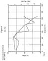
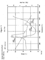
- Figure 3 shows as a function of time the weight changes for the sample and the heat transfer to or from the sample as it was heated at 5°C per minute.
- Figure 4 shows the same data as a function of temperature.
- Figure 5 shows the corresponding mass spectroscopy data for the process gas as a function of time. Discrete reactions occurring at about 490°C, 600°C, 780°C and 850°C are evident from the data.
- the weight data shows an initial weight gain below 490°C, followed by weight loss at 490°C, then weight gain again above 490°C followed by weight loss at 600°C.
- the sample weight increased again until 780°C and then abruptly lost weight at 850°C. Following on from this the weight increased again before stabilizing near 1050°C.
- This staircase effect is explained by the sample gaining oxygen to fill anion vacancies when the weight is increasing and that sulphur is being displaced and evolved as sulphur dioxide when the weight is decreasing.
- the weight gain above this temperature may be due to the filling of anion vacancies in this structure with oxygen.
- the overall mass spectroscopic and mass balance analysis indicates that the compound has a chemical composition of approximately BaAl 2 S 2 O 2 . Evolution of carbon dioxide at temperatures above 1100°C is also observed that may be due to oxidation of carbides or decomposition of carbonates initially present as an impurity in the samples or in the crucible.
- a 4.3 milligram powder sample similar to that in Example 1 was subject to combined thermogravimetric analysis, differential scanning calorimetry and mass spectroscopic analysis of the process gas.
- the process gas was also 2000 ppm of oxygen in argon, but the temperature ramp rate was about 20°C per minute rather than 5°C per minute.
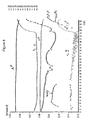
- the weight change of the sample, the heat flow to or from the sample and the sample temperature are shown as a function of time in Figure 6 .
- the mass spectroscopy data for the process gas is shown in Figure 7 for atomic mass units 12 through 20, in Figure 8 for atomic mass units 21 through 40, in Figure 9 for atomic mass units 42 through 54 and in Figure 10 for mass units 64 to 80.
- the reactions occurring at about 490°C and 600°C are accompanied by a weight loss.
- the reactions at about 780°C and 840°C are accompanied by weight loss which continues beyond 850°C rather than a weight gain as in example 1.
- the overall weight change is similar and the end product has a similar composition. Any observed differences in the weight changes are likely due to less time being available for each reaction in the series of reactions to go to completion before the onset of the next reaction.
- the instantaneous rate of reaction was higher, and the reduction in the oxygen concentration as the reactions consume oxygen as measured by the concentration of mass units 16 and 32 in Figures 7 and 8 is more apparent than it was for example 1.
- the calorimetry data shows endothermic peaks associated with the reactions, as in Example 1, but an exothermic rather than an endothermic peak at 840°C, indicating that a substantial internal reorganization of the crystal lattice occurred, but that less sulphur dioxide was evolved, reducing the size of a coincident endotherm.
- the process gas was switched to air, at which point a substantial exotherm is observed coinciding with a significant sample weight gain, as well as a significant increase in carbon dioxide (mass unit 44) in the process gas stream that may be due to oxidation of carbides in the sample or the crucible. Also observed are a brief dip in the oxygen concentration as it is rising with the introduction of air and a corresponding peak in sulfur dioxide (mass units 44, 46, 64 and 66). Analysis of the mass spectroscopy results in combination with the mass balance of the sample indicates that the BaAl 2 S 2 O 2 compound formed with 2000 ppm oxygen in argon reacted with the air to directly form alumina and barium sulfate.
- This example illustrates how potentially undesirable compounds can form in association with phosphor materials when the phosphor materials are heated in air.
- thermogravimetric and calorimetric data is shown in Figure 11 .
- the corresponding mass spectroscopy data is shown in Figure 12 .
- the mass spectroscopy data indicates that the reactions at 420°C and 475°C involve consumption of water vapour and oxygen as evidenced by the atomic mass 18 and atomic mass 32 data and evolution of sulphur dioxide, but not hydrogen sulphide.
- This data combined with the mass balance data indicates that a compound with a composition approximately represented by the formula BaAl 2 S 2 O(OH) 2 is formed. The formation of this compound precludes the formation of BaAl 2 S 2 O 2 at a later step.
- the differences are presumed due to a variable oxide or hydroxide content due to reaction of the sulphide materials with at least one of oxygen and moisture from the air. Above 600°C, the samples gained about 0.5% in weight. Following cooling and upon reheating under air, the sample weight was stable until the temperature reached 1060°C, at which point the samples within a few seconds suffered about a 10% weight loss. As the temperature was maintained at 1100°C, the samples slowly regained weight to achieve essentially their original weight. The weight changes in the sample at 1060°C correspond approximately to a reaction product comprising barium sulphide and alumina. The subsequent weight gain is associated with conversion of the barium sulphide to barium sulfate. These reaction products were confirmed with x-ray diffraction measurements on fresh samples taken to the respective points in the thermal program.
- This compound decomposes suddenly in air at 1060°C to form a product comprising primarily barium sulphide and alumina, and minor quantities of barium aluminate.
- the thermal analysis data in the temperature range 750°C to 1100°C for heating under argon containing 125 ppm of oxygen is expanded in Figure 14 . It shows exothermic anomalies at 840°C, 950°C 980°C and an endothermic anomaly at 1040°C corresponding to the initiation of the fast decomposition under air at 1060°C. The exothermic anomaly at 980°C is the largest. This data is compared to the calorimetry data in the same temperature for the sample of example 1 and 2.
- the anomaly at 840°C was endothermic and the others were not present.
- the anomaly at 840°C was exothermic and the remainder were present but barely perceptable.
- the thick film substrate was comprised of a 5 cm by 5 cm alumina substrate having a thickness of 0.1 cm.
- a gold electrode was deposited on the substrate, followed with a thick film high dielectric constant dielectric layer in accordance with the methods exemplified in Applicant's co-pending international application PCT CA00/00561 filed May 12, 2000 .
- the phosphor film was electron beam evaporated on top of the barium titanate layer using dual source electron beam evaporation, according to the methods described in Applicant's co-pending U.S. Patent Application 09/747,315 filed December 22, 2000 .
- the two evaporation sources were aluminum sulphide and a fused mixture of barium sulphide and europium sulphide in the form of pellets.
- the phosphor deposition was carried out in a low pressure atmosphere of hydrogen sulphide at a pressure of 10 -2 pascal to 2.66 ⁇ ( 10 -2 pascal (8 x 10 -5 to 2 x 10 -4 torr) and with the substrate at a temperature in the range of about 350°C to 500°C.
- the deposition was carried out by electron beam evaporation using the dual sources.
- the deposition rate of the aluminum sulphide, as measured in the absence of the remaining constituents using a quartz crystal monitor, was in the range of 5 to 7 Angstroms per second and the deposition rate of the remaining constituents in the absence of aluminum sulphide, also as measured using a quartz crystal monitor, was in the range of 3.5 to 5.5 Angstroms per second.
- the deposited phosphor film thickness was in the range of about 3000 to 4500 Angstroms.
- the elemental composition of the phosphor layer was measured using energy dispersive analysis by x-rays (EDX) and the atomic ratio of oxygen to sulphur was found to be in the range of about 0.1 to 0.2.
- EDX energy dispersive analysis by x-rays
- the phosphor-coated substrates were heat treated under an argon atmosphere containing 10% of oxygen at a temperature of about 850°C for about 2 minutes.
- a 50 nanometer thick alumina thin film and an indium tin oxide transparent conductor were deposited over the phosphor to provide a second electrode.
- a second device constructed in a similar manner was constructed, but with an oxygen to sulphur ratio prior to heat treatment in the range of about 2:1 to 3:1 and a heat treatment atmosphere consisting of pure nitrogen at a temperature of about 700°C.
- the two devices were tested using alternating polarity 32 microsecond wide square-wave pulses and a frequency of 120 Hz giving 240 light pulses per second.
- the pulse amplitude was varied in increments of 10 volts up to 260 volts.
- the former device was operated for about 1000 hours before losing half of its initial luminance compared to about 100 hours for the latter device.
Landscapes
- Chemical & Material Sciences (AREA)
- Engineering & Computer Science (AREA)
- Inorganic Chemistry (AREA)
- Materials Engineering (AREA)
- Organic Chemistry (AREA)
- Manufacturing & Machinery (AREA)
- Luminescent Compositions (AREA)
- Electroluminescent Light Sources (AREA)
Applications Claiming Priority (3)
| Application Number | Priority Date | Filing Date | Title |
|---|---|---|---|
| US37278102P | 2002-04-17 | 2002-04-17 | |
| US372781P | 2002-04-17 | ||
| PCT/CA2003/000568 WO2003090501A1 (en) | 2002-04-17 | 2003-04-16 | Oxygen substituted barium thioaluminate phosphor materials |
Publications (2)
| Publication Number | Publication Date |
|---|---|
| EP1498011A1 EP1498011A1 (en) | 2005-01-19 |
| EP1498011B1 true EP1498011B1 (en) | 2009-04-15 |
Family
ID=29250906
Family Applications (1)
| Application Number | Title | Priority Date | Filing Date |
|---|---|---|---|
| EP03714586A Expired - Lifetime EP1498011B1 (en) | 2002-04-17 | 2003-04-16 | Oxygen substituted barium thioaluminate phosphor materials |
Country Status (10)
| Country | Link |
|---|---|
| US (2) | US7112373B2 (https=) |
| EP (1) | EP1498011B1 (https=) |
| JP (1) | JP4500054B2 (https=) |
| KR (1) | KR20050005452A (https=) |
| CN (1) | CN100542364C (https=) |
| AT (1) | ATE429141T1 (https=) |
| AU (1) | AU2003218840A1 (https=) |
| CA (1) | CA2482833A1 (https=) |
| DE (1) | DE60327193D1 (https=) |
| WO (1) | WO2003090501A1 (https=) |
Families Citing this family (7)
| Publication number | Priority date | Publication date | Assignee | Title |
|---|---|---|---|---|
| JP4263001B2 (ja) | 2003-03-06 | 2009-05-13 | アイファイヤー アイピー コーポレイション | スパッタリングターゲット |
| US7812522B2 (en) | 2004-07-22 | 2010-10-12 | Ifire Ip Corporation | Aluminum oxide and aluminum oxynitride layers for use with phosphors for electroluminescent displays |
| US7427367B2 (en) | 2004-08-06 | 2008-09-23 | Ifire Technology Corp. | Barium thioaluminate phosphor materials with novel crystal structures |
| CN100560688C (zh) | 2005-09-23 | 2009-11-18 | 大连路明发光科技股份有限公司 | 长余辉发光材料及其制造方法 |
| US8456082B2 (en) | 2008-12-01 | 2013-06-04 | Ifire Ip Corporation | Surface-emission light source with uniform illumination |
| CN102370999A (zh) * | 2010-08-04 | 2012-03-14 | 曼尼托沃食品服务有限公司 | 使用脉宽调制的制冰机离子清洁器的功率控制方法和系统 |
| CN112159213B (zh) * | 2020-10-29 | 2023-07-18 | 贵州赛义光电科技有限公司 | 一种零光衰发光陶瓷及其制备方法 |
Family Cites Families (10)
| Publication number | Priority date | Publication date | Assignee | Title |
|---|---|---|---|---|
| US5656999A (en) | 1995-05-02 | 1997-08-12 | Campbell; David C. | Fluid leak containment system |
| US5656888A (en) * | 1995-11-13 | 1997-08-12 | Sun; Sey-Shing | Oxygen-doped thiogallate phosphor |
| JP2000081483A (ja) | 1998-09-04 | 2000-03-21 | Furuno Electric Co Ltd | 魚群探知装置 |
| JP4077131B2 (ja) * | 2000-03-23 | 2008-04-16 | 日本放送協会 | フルカラー薄膜elディスプレイパネル |
| JP3987263B2 (ja) * | 2000-03-23 | 2007-10-03 | 日本放送協会 | アルミネート青色発光蛍光体材料とそれを用いて構成した青色発光薄膜エレクトロルミネッセンス素子 |
| JP3501742B2 (ja) * | 2000-10-03 | 2004-03-02 | Tdk株式会社 | 積層蛍光体およびelパネル |
| US6761835B2 (en) * | 2000-07-07 | 2004-07-13 | Tdk Corporation | Phosphor multilayer and EL panel |
| JP3704057B2 (ja) * | 2000-07-07 | 2005-10-05 | ザ ウエステイム コーポレイション | 蛍光体薄膜その製造方法、およびelパネル |
| JP3479273B2 (ja) * | 2000-09-21 | 2003-12-15 | Tdk株式会社 | 蛍光体薄膜その製造方法およびelパネル |
| JP3704068B2 (ja) * | 2001-07-27 | 2005-10-05 | ザ ウエステイム コーポレイション | Elパネル |
-
2003
- 2003-04-16 CN CNB038086107A patent/CN100542364C/zh not_active Expired - Fee Related
- 2003-04-16 WO PCT/CA2003/000568 patent/WO2003090501A1/en not_active Ceased
- 2003-04-16 JP JP2003587142A patent/JP4500054B2/ja not_active Expired - Fee Related
- 2003-04-16 DE DE60327193T patent/DE60327193D1/de not_active Expired - Lifetime
- 2003-04-16 KR KR10-2004-7016743A patent/KR20050005452A/ko not_active Ceased
- 2003-04-16 AT AT03714586T patent/ATE429141T1/de not_active IP Right Cessation
- 2003-04-16 CA CA002482833A patent/CA2482833A1/en not_active Abandoned
- 2003-04-16 AU AU2003218840A patent/AU2003218840A1/en not_active Abandoned
- 2003-04-16 EP EP03714586A patent/EP1498011B1/en not_active Expired - Lifetime
- 2003-04-17 US US10/417,901 patent/US7112373B2/en not_active Expired - Fee Related
-
2006
- 2006-05-11 US US11/432,453 patent/US7597969B2/en not_active Expired - Fee Related
Also Published As
| Publication number | Publication date |
|---|---|
| ATE429141T1 (de) | 2009-05-15 |
| US7597969B2 (en) | 2009-10-06 |
| JP2005523375A (ja) | 2005-08-04 |
| AU2003218840A8 (en) | 2003-11-03 |
| CN100542364C (zh) | 2009-09-16 |
| CN1647587A (zh) | 2005-07-27 |
| US20060267484A1 (en) | 2006-11-30 |
| CA2482833A1 (en) | 2003-10-30 |
| EP1498011A1 (en) | 2005-01-19 |
| DE60327193D1 (de) | 2009-05-28 |
| AU2003218840A1 (en) | 2003-11-03 |
| WO2003090501A1 (en) | 2003-10-30 |
| US20040013906A1 (en) | 2004-01-22 |
| US7112373B2 (en) | 2006-09-26 |
| KR20050005452A (ko) | 2005-01-13 |
| JP4500054B2 (ja) | 2010-07-14 |
Similar Documents
| Publication | Publication Date | Title |
|---|---|---|
| EP1493307B1 (en) | Yttrium substituted barium thioaluminate phosphor materials | |
| US6919682B2 (en) | Magnesium barium thioaluminate and related phosphor materials | |
| EP1346007A1 (en) | Multiple source deposition process | |
| CA2447626C (en) | Single source sputtering of thioaluminate phosphor films | |
| EP1498011B1 (en) | Oxygen substituted barium thioaluminate phosphor materials | |
| US7427367B2 (en) | Barium thioaluminate phosphor materials with novel crystal structures | |
| Kryshtab et al. | Preparation and properties of thin ZnS: Cu films phosphors | |
| US6793782B2 (en) | Sputter deposition process for electroluminescent phosphors | |
| JP2005523375A5 (https=) | ||
| US7622149B2 (en) | Reactive metal sources and deposition method for thioaluminate phosphors | |
| JP4247315B2 (ja) | マグネシウムカルシウムチオアルミネート蛍光体 | |
| US7556721B2 (en) | Thiosilicate phosphor compositions and deposition methods using barium-silicon vacuum deposition sources for deposition of thiosilicate phosphor films | |
| Braunger et al. | Improved Growth Of Srga2s4 Thin Film Electroluminescence Phosphors | |
| Guo et al. | P‐87: Flux Effects on BaAl2S4: Eu, F Blue‐phosphor |
Legal Events
| Date | Code | Title | Description |
|---|---|---|---|
| PUAI | Public reference made under article 153(3) epc to a published international application that has entered the european phase |
Free format text: ORIGINAL CODE: 0009012 |
|
| 17P | Request for examination filed |
Effective date: 20041110 |
|
| AK | Designated contracting states |
Kind code of ref document: A1 Designated state(s): AT BE BG CH CY CZ DE DK EE ES FI FR GB GR HU IE IT LI LU MC NL PT RO SE SI SK TR |
|
| AX | Request for extension of the european patent |
Extension state: AL LT LV MK |
|
| RAP1 | Party data changed (applicant data changed or rights of an application transferred) |
Owner name: IFIRE TECHNOLOGY CORP. Owner name: SANYO ELECTRIC CO., LTD. |
|
| 17Q | First examination report despatched |
Effective date: 20070814 |
|
| RAP1 | Party data changed (applicant data changed or rights of an application transferred) |
Owner name: SANYO ELECTRIC CO., LTD. Owner name: IFIRE IP CORPORATION |
|
| GRAP | Despatch of communication of intention to grant a patent |
Free format text: ORIGINAL CODE: EPIDOSNIGR1 |
|
| GRAS | Grant fee paid |
Free format text: ORIGINAL CODE: EPIDOSNIGR3 |
|
| GRAA | (expected) grant |
Free format text: ORIGINAL CODE: 0009210 |
|
| AK | Designated contracting states |
Kind code of ref document: B1 Designated state(s): AT BE BG CH CY CZ DE DK EE ES FI FR GB GR HU IE IT LI LU MC NL PT RO SE SI SK TR |
|
| REG | Reference to a national code |
Ref country code: GB Ref legal event code: FG4D Ref country code: CH Ref legal event code: EP |
|
| REG | Reference to a national code |
Ref country code: IE Ref legal event code: FG4D |
|
| REF | Corresponds to: |
Ref document number: 60327193 Country of ref document: DE Date of ref document: 20090528 Kind code of ref document: P |
|
| RAP2 | Party data changed (patent owner data changed or rights of a patent transferred) |
Owner name: IFIRE IP CORPORATION Owner name: SANYO ELECTRIC CO., LTD. |
|
| NLV1 | Nl: lapsed or annulled due to failure to fulfill the requirements of art. 29p and 29m of the patents act | ||
| PG25 | Lapsed in a contracting state [announced via postgrant information from national office to epo] |
Ref country code: ES Free format text: LAPSE BECAUSE OF FAILURE TO SUBMIT A TRANSLATION OF THE DESCRIPTION OR TO PAY THE FEE WITHIN THE PRESCRIBED TIME-LIMIT Effective date: 20090726 Ref country code: AT Free format text: LAPSE BECAUSE OF FAILURE TO SUBMIT A TRANSLATION OF THE DESCRIPTION OR TO PAY THE FEE WITHIN THE PRESCRIBED TIME-LIMIT Effective date: 20090415 Ref country code: PT Free format text: LAPSE BECAUSE OF FAILURE TO SUBMIT A TRANSLATION OF THE DESCRIPTION OR TO PAY THE FEE WITHIN THE PRESCRIBED TIME-LIMIT Effective date: 20090915 Ref country code: FI Free format text: LAPSE BECAUSE OF FAILURE TO SUBMIT A TRANSLATION OF THE DESCRIPTION OR TO PAY THE FEE WITHIN THE PRESCRIBED TIME-LIMIT Effective date: 20090415 |
|
| PG25 | Lapsed in a contracting state [announced via postgrant information from national office to epo] |
Ref country code: SE Free format text: LAPSE BECAUSE OF FAILURE TO SUBMIT A TRANSLATION OF THE DESCRIPTION OR TO PAY THE FEE WITHIN THE PRESCRIBED TIME-LIMIT Effective date: 20090715 Ref country code: NL Free format text: LAPSE BECAUSE OF FAILURE TO SUBMIT A TRANSLATION OF THE DESCRIPTION OR TO PAY THE FEE WITHIN THE PRESCRIBED TIME-LIMIT Effective date: 20090415 Ref country code: SI Free format text: LAPSE BECAUSE OF FAILURE TO SUBMIT A TRANSLATION OF THE DESCRIPTION OR TO PAY THE FEE WITHIN THE PRESCRIBED TIME-LIMIT Effective date: 20090415 |
|
| REG | Reference to a national code |
Ref country code: CH Ref legal event code: PL |
|
| PG25 | Lapsed in a contracting state [announced via postgrant information from national office to epo] |
Ref country code: LI Free format text: LAPSE BECAUSE OF NON-PAYMENT OF DUE FEES Effective date: 20090430 Ref country code: RO Free format text: LAPSE BECAUSE OF FAILURE TO SUBMIT A TRANSLATION OF THE DESCRIPTION OR TO PAY THE FEE WITHIN THE PRESCRIBED TIME-LIMIT Effective date: 20090415 Ref country code: EE Free format text: LAPSE BECAUSE OF FAILURE TO SUBMIT A TRANSLATION OF THE DESCRIPTION OR TO PAY THE FEE WITHIN THE PRESCRIBED TIME-LIMIT Effective date: 20090415 Ref country code: DK Free format text: LAPSE BECAUSE OF FAILURE TO SUBMIT A TRANSLATION OF THE DESCRIPTION OR TO PAY THE FEE WITHIN THE PRESCRIBED TIME-LIMIT Effective date: 20090415 Ref country code: CH Free format text: LAPSE BECAUSE OF NON-PAYMENT OF DUE FEES Effective date: 20090430 Ref country code: CZ Free format text: LAPSE BECAUSE OF FAILURE TO SUBMIT A TRANSLATION OF THE DESCRIPTION OR TO PAY THE FEE WITHIN THE PRESCRIBED TIME-LIMIT Effective date: 20090415 |
|
| PLBE | No opposition filed within time limit |
Free format text: ORIGINAL CODE: 0009261 |
|
| STAA | Information on the status of an ep patent application or granted ep patent |
Free format text: STATUS: NO OPPOSITION FILED WITHIN TIME LIMIT |
|
| PG25 | Lapsed in a contracting state [announced via postgrant information from national office to epo] |
Ref country code: BE Free format text: LAPSE BECAUSE OF FAILURE TO SUBMIT A TRANSLATION OF THE DESCRIPTION OR TO PAY THE FEE WITHIN THE PRESCRIBED TIME-LIMIT Effective date: 20090415 Ref country code: SK Free format text: LAPSE BECAUSE OF FAILURE TO SUBMIT A TRANSLATION OF THE DESCRIPTION OR TO PAY THE FEE WITHIN THE PRESCRIBED TIME-LIMIT Effective date: 20090415 |
|
| 26N | No opposition filed |
Effective date: 20100118 |
|
| PG25 | Lapsed in a contracting state [announced via postgrant information from national office to epo] |
Ref country code: BG Free format text: LAPSE BECAUSE OF FAILURE TO SUBMIT A TRANSLATION OF THE DESCRIPTION OR TO PAY THE FEE WITHIN THE PRESCRIBED TIME-LIMIT Effective date: 20090715 |
|
| PG25 | Lapsed in a contracting state [announced via postgrant information from national office to epo] |
Ref country code: IE Free format text: LAPSE BECAUSE OF NON-PAYMENT OF DUE FEES Effective date: 20090416 Ref country code: MC Free format text: LAPSE BECAUSE OF NON-PAYMENT OF DUE FEES Effective date: 20090430 |
|
| PG25 | Lapsed in a contracting state [announced via postgrant information from national office to epo] |
Ref country code: GR Free format text: LAPSE BECAUSE OF FAILURE TO SUBMIT A TRANSLATION OF THE DESCRIPTION OR TO PAY THE FEE WITHIN THE PRESCRIBED TIME-LIMIT Effective date: 20090716 |
|
| REG | Reference to a national code |
Ref country code: FR Ref legal event code: ST Effective date: 20101230 |
|
| PG25 | Lapsed in a contracting state [announced via postgrant information from national office to epo] |
Ref country code: FR Free format text: LAPSE BECAUSE OF NON-PAYMENT OF DUE FEES Effective date: 20100430 |
|
| PG25 | Lapsed in a contracting state [announced via postgrant information from national office to epo] |
Ref country code: IT Free format text: LAPSE BECAUSE OF FAILURE TO SUBMIT A TRANSLATION OF THE DESCRIPTION OR TO PAY THE FEE WITHIN THE PRESCRIBED TIME-LIMIT Effective date: 20090415 |
|
| PG25 | Lapsed in a contracting state [announced via postgrant information from national office to epo] |
Ref country code: LU Free format text: LAPSE BECAUSE OF NON-PAYMENT OF DUE FEES Effective date: 20090416 |
|
| PG25 | Lapsed in a contracting state [announced via postgrant information from national office to epo] |
Ref country code: HU Free format text: LAPSE BECAUSE OF FAILURE TO SUBMIT A TRANSLATION OF THE DESCRIPTION OR TO PAY THE FEE WITHIN THE PRESCRIBED TIME-LIMIT Effective date: 20091016 |
|
| PG25 | Lapsed in a contracting state [announced via postgrant information from national office to epo] |
Ref country code: TR Free format text: LAPSE BECAUSE OF FAILURE TO SUBMIT A TRANSLATION OF THE DESCRIPTION OR TO PAY THE FEE WITHIN THE PRESCRIBED TIME-LIMIT Effective date: 20090415 |
|
| PG25 | Lapsed in a contracting state [announced via postgrant information from national office to epo] |
Ref country code: CY Free format text: LAPSE BECAUSE OF FAILURE TO SUBMIT A TRANSLATION OF THE DESCRIPTION OR TO PAY THE FEE WITHIN THE PRESCRIBED TIME-LIMIT Effective date: 20090415 |
|
| PGFP | Annual fee paid to national office [announced via postgrant information from national office to epo] |
Ref country code: FR Payment date: 20090601 Year of fee payment: 7 |
|
| PGFP | Annual fee paid to national office [announced via postgrant information from national office to epo] |
Ref country code: DE Payment date: 20160426 Year of fee payment: 14 Ref country code: GB Payment date: 20160421 Year of fee payment: 14 |
|
| REG | Reference to a national code |
Ref country code: DE Ref legal event code: R119 Ref document number: 60327193 Country of ref document: DE |
|
| GBPC | Gb: european patent ceased through non-payment of renewal fee |
Effective date: 20170416 |
|
| PG25 | Lapsed in a contracting state [announced via postgrant information from national office to epo] |
Ref country code: DE Free format text: LAPSE BECAUSE OF NON-PAYMENT OF DUE FEES Effective date: 20171103 |
|
| PG25 | Lapsed in a contracting state [announced via postgrant information from national office to epo] |
Ref country code: GB Free format text: LAPSE BECAUSE OF NON-PAYMENT OF DUE FEES Effective date: 20170416 |