EP1497600B1 - Mounting arrangement for a refrigerator fan - Google Patents
Mounting arrangement for a refrigerator fan Download PDFInfo
- Publication number
- EP1497600B1 EP1497600B1 EP03746788A EP03746788A EP1497600B1 EP 1497600 B1 EP1497600 B1 EP 1497600B1 EP 03746788 A EP03746788 A EP 03746788A EP 03746788 A EP03746788 A EP 03746788A EP 1497600 B1 EP1497600 B1 EP 1497600B1
- Authority
- EP
- European Patent Office
- Prior art keywords
- mounting arrangement
- arrangement according
- marginal portion
- flexible support
- support frame
- Prior art date
- Legal status (The legal status is an assumption and is not a legal conclusion. Google has not performed a legal analysis and makes no representation as to the accuracy of the status listed.)
- Expired - Lifetime
Links
- 239000012528 membrane Substances 0.000 claims description 6
- 239000013536 elastomeric material Substances 0.000 claims description 5
- 230000002093 peripheral effect Effects 0.000 claims description 5
- 238000006073 displacement reaction Methods 0.000 claims description 4
- 230000005489 elastic deformation Effects 0.000 claims description 2
- 230000000717 retained effect Effects 0.000 claims description 2
- 238000001816 cooling Methods 0.000 description 15
- 238000007710 freezing Methods 0.000 description 8
- 230000008014 freezing Effects 0.000 description 8
- 238000010276 construction Methods 0.000 description 4
- 239000000463 material Substances 0.000 description 2
- 238000010521 absorption reaction Methods 0.000 description 1
- 230000006978 adaptation Effects 0.000 description 1
- 230000000712 assembly Effects 0.000 description 1
- 238000000429 assembly Methods 0.000 description 1
- 230000005540 biological transmission Effects 0.000 description 1
- 230000007812 deficiency Effects 0.000 description 1
- 238000011144 upstream manufacturing Methods 0.000 description 1
Images


Classifications
-
- H—ELECTRICITY
- H02—GENERATION; CONVERSION OR DISTRIBUTION OF ELECTRIC POWER
- H02K—DYNAMO-ELECTRIC MACHINES
- H02K5/00—Casings; Enclosures; Supports
- H02K5/24—Casings; Enclosures; Supports specially adapted for suppression or reduction of noise or vibrations
-
- F—MECHANICAL ENGINEERING; LIGHTING; HEATING; WEAPONS; BLASTING
- F04—POSITIVE - DISPLACEMENT MACHINES FOR LIQUIDS; PUMPS FOR LIQUIDS OR ELASTIC FLUIDS
- F04D—NON-POSITIVE-DISPLACEMENT PUMPS
- F04D29/00—Details, component parts, or accessories
- F04D29/60—Mounting; Assembling; Disassembling
- F04D29/601—Mounting; Assembling; Disassembling specially adapted for elastic fluid pumps
-
- F—MECHANICAL ENGINEERING; LIGHTING; HEATING; WEAPONS; BLASTING
- F04—POSITIVE - DISPLACEMENT MACHINES FOR LIQUIDS; PUMPS FOR LIQUIDS OR ELASTIC FLUIDS
- F04D—NON-POSITIVE-DISPLACEMENT PUMPS
- F04D29/00—Details, component parts, or accessories
- F04D29/66—Combating cavitation, whirls, noise, vibration or the like; Balancing
- F04D29/661—Combating cavitation, whirls, noise, vibration or the like; Balancing especially adapted for elastic fluid pumps
- F04D29/668—Combating cavitation, whirls, noise, vibration or the like; Balancing especially adapted for elastic fluid pumps damping or preventing mechanical vibrations
-
- F—MECHANICAL ENGINEERING; LIGHTING; HEATING; WEAPONS; BLASTING
- F25—REFRIGERATION OR COOLING; COMBINED HEATING AND REFRIGERATION SYSTEMS; HEAT PUMP SYSTEMS; MANUFACTURE OR STORAGE OF ICE; LIQUEFACTION SOLIDIFICATION OF GASES
- F25D—REFRIGERATORS; COLD ROOMS; ICE-BOXES; COOLING OR FREEZING APPARATUS NOT OTHERWISE PROVIDED FOR
- F25D17/00—Arrangements for circulating cooling fluids; Arrangements for circulating gas, e.g. air, within refrigerated spaces
- F25D17/04—Arrangements for circulating cooling fluids; Arrangements for circulating gas, e.g. air, within refrigerated spaces for circulating air, e.g. by convection
- F25D17/06—Arrangements for circulating cooling fluids; Arrangements for circulating gas, e.g. air, within refrigerated spaces for circulating air, e.g. by convection by forced circulation
- F25D17/062—Arrangements for circulating cooling fluids; Arrangements for circulating gas, e.g. air, within refrigerated spaces for circulating air, e.g. by convection by forced circulation in household refrigerators
- F25D17/065—Arrangements for circulating cooling fluids; Arrangements for circulating gas, e.g. air, within refrigerated spaces for circulating air, e.g. by convection by forced circulation in household refrigerators with compartments at different temperatures
-
- F—MECHANICAL ENGINEERING; LIGHTING; HEATING; WEAPONS; BLASTING
- F25—REFRIGERATION OR COOLING; COMBINED HEATING AND REFRIGERATION SYSTEMS; HEAT PUMP SYSTEMS; MANUFACTURE OR STORAGE OF ICE; LIQUEFACTION SOLIDIFICATION OF GASES
- F25B—REFRIGERATION MACHINES, PLANTS OR SYSTEMS; COMBINED HEATING AND REFRIGERATION SYSTEMS; HEAT PUMP SYSTEMS
- F25B2500/00—Problems to be solved
- F25B2500/13—Vibrations
-
- F—MECHANICAL ENGINEERING; LIGHTING; HEATING; WEAPONS; BLASTING
- F25—REFRIGERATION OR COOLING; COMBINED HEATING AND REFRIGERATION SYSTEMS; HEAT PUMP SYSTEMS; MANUFACTURE OR STORAGE OF ICE; LIQUEFACTION SOLIDIFICATION OF GASES
- F25D—REFRIGERATORS; COLD ROOMS; ICE-BOXES; COOLING OR FREEZING APPARATUS NOT OTHERWISE PROVIDED FOR
- F25D2201/00—Insulation
- F25D2201/30—Insulation with respect to sound
-
- F—MECHANICAL ENGINEERING; LIGHTING; HEATING; WEAPONS; BLASTING
- F25—REFRIGERATION OR COOLING; COMBINED HEATING AND REFRIGERATION SYSTEMS; HEAT PUMP SYSTEMS; MANUFACTURE OR STORAGE OF ICE; LIQUEFACTION SOLIDIFICATION OF GASES
- F25D—REFRIGERATORS; COLD ROOMS; ICE-BOXES; COOLING OR FREEZING APPARATUS NOT OTHERWISE PROVIDED FOR
- F25D2317/00—Details or arrangements for circulating cooling fluids; Details or arrangements for circulating gas, e.g. air, within refrigerated spaces, not provided for in other groups of this subclass
- F25D2317/06—Details or arrangements for circulating cooling fluids; Details or arrangements for circulating gas, e.g. air, within refrigerated spaces, not provided for in other groups of this subclass with forced air circulation
- F25D2317/065—Details or arrangements for circulating cooling fluids; Details or arrangements for circulating gas, e.g. air, within refrigerated spaces, not provided for in other groups of this subclass with forced air circulation characterised by the air return
- F25D2317/0653—Details or arrangements for circulating cooling fluids; Details or arrangements for circulating gas, e.g. air, within refrigerated spaces, not provided for in other groups of this subclass with forced air circulation characterised by the air return through the mullion
-
- F—MECHANICAL ENGINEERING; LIGHTING; HEATING; WEAPONS; BLASTING
- F25—REFRIGERATION OR COOLING; COMBINED HEATING AND REFRIGERATION SYSTEMS; HEAT PUMP SYSTEMS; MANUFACTURE OR STORAGE OF ICE; LIQUEFACTION SOLIDIFICATION OF GASES
- F25D—REFRIGERATORS; COLD ROOMS; ICE-BOXES; COOLING OR FREEZING APPARATUS NOT OTHERWISE PROVIDED FOR
- F25D2317/00—Details or arrangements for circulating cooling fluids; Details or arrangements for circulating gas, e.g. air, within refrigerated spaces, not provided for in other groups of this subclass
- F25D2317/06—Details or arrangements for circulating cooling fluids; Details or arrangements for circulating gas, e.g. air, within refrigerated spaces, not provided for in other groups of this subclass with forced air circulation
- F25D2317/068—Details or arrangements for circulating cooling fluids; Details or arrangements for circulating gas, e.g. air, within refrigerated spaces, not provided for in other groups of this subclass with forced air circulation characterised by the fans
- F25D2317/0681—Details thereof
-
- F—MECHANICAL ENGINEERING; LIGHTING; HEATING; WEAPONS; BLASTING
- F25—REFRIGERATION OR COOLING; COMBINED HEATING AND REFRIGERATION SYSTEMS; HEAT PUMP SYSTEMS; MANUFACTURE OR STORAGE OF ICE; LIQUEFACTION SOLIDIFICATION OF GASES
- F25D—REFRIGERATORS; COLD ROOMS; ICE-BOXES; COOLING OR FREEZING APPARATUS NOT OTHERWISE PROVIDED FOR
- F25D2400/00—General features of, or devices for refrigerators, cold rooms, ice-boxes, or for cooling or freezing apparatus not covered by any other subclass
- F25D2400/04—Refrigerators with a horizontal mullion
Definitions
- the present invention refers to a mounting arrangement for a fan used to provide the forced air circulation through the evaporator compartment in a refrigerator of the simple or combined types, in which each storing compartment defined inside a cabinet is submitted to an airflow that is forced to pass through the evaporator.
- the evaporator is positioned inside an air cooling compartment generally provided in the rear upper region of the refrigerator cabinet and presenting at least one circulated air inlet, which receives the air coming from the storing compartments of the refrigerator, and a refrigerated air outlet directed to said storing compartments.
- the air cooling compartment is generally positioned behind the freezing compartment and in communication with the latter and with the refrigerating compartment through said refrigerated air outlet of the air cooling compartment, which outlet is opened to an adequate system of refrigerated air directing ducts.
- the refrigerator In order to provide the necessary forced air circulation through the evaporator mounted in the air cooling compartment, drawing the air that is forced to circulate through the freezing and the refrigerating compartments, and returning the air to said freezing and refrigerating compartments after it has been refrigerated by the evaporator, the refrigerator is provided with a fan of axial flow, whose shaft is generally horizontally disposed and which is mounted to a divisional wall of the air cooling compartment through the air outlet of the latter defined by an opening in said divisional wall of the air cooling compartment.
- the fan comprising an electric motor to whose shaft is mounted a propeller, has said motor affixed directly to the wall of the air cooling compartment by means of a rigid support, which can take different forms, such as for example a tubular shell affixed to said divisional wall, coaxially to the outlet opening of the air cooling compartment.
- Another known prior art solution uses a system in which the fixation is also made directly to the electric motor, but through a flexible annular support of elastomeric material, surrounding the body of the electric motor and incorporating substantially radial rods, whose ends are affixed to said divisional wall of the cabinet structure on which is provided the outlet opening of the air cooling compartment.
- the present invention has the generic object to provide a mounting arrangement for a fan of the type considered herein, which is developed to assure an adequate absorption of the motor vibrations, utilizing a resistant construction which is easily and quickly assembled and disassembled and which presents good performance in the forced air circulation.
- the present mounting arrangement is directed to a refrigerator fan comprising an electric motor, to whose shaft is affixed a propeller with an axial flow passing through a refrigerated air outlet provided through an internal divisional wall of the refrigerator.
- the present arrangement comprises a support frame, having a marginal portion external to the contour of rotation of the propeller and incorporating a central hub in which is affixed the electric motor.
- a flexible support in the form of an annular flange, presenting an outer portion, which is peripherally and removably affixed to the internal divisional wall, along the contour of the refrigerated air outlet; an inner portion provided with a central opening and with retaining means, which are removably locked to the marginal portion of the support frame, in a condition in which said marginal portion is axially aligned with the central opening of the flexible support; and a membrane portion interconnecting the outer and inner portions, in order to allow for small relative axial and radial displacements therebetween.
- the construction proposed herein allows the fan to be easily and rapidly attached to the inner portion of the flexible support, whose outer portion is mounted to the internal divisional wall of the refrigerator, preferably by simply fitting a peripheral groove on the edge of the internal divisional wall that defines the contour of the opening of the refrigerated air outlet.
- Both the inner and the outer portions of the flexible support which are preferably made of an elastomeric material, are united by the membrane portion, which allows for the relative movement between the two other portions of the flexible support, absorbing small displacements and vibrations of the electric motor-propeller assembly.
- the invention is applied to a combined refrigerator with forced air circulation, comprising a freezing compartment 1 and a refrigerating compartment 2 which are superposed and separated by an intermediate wall 3.
- the refrigerator further comprises an air cooling compartment 4, generally located close to the rear region of the freezing compartment 1 and lodging an evaporator 5.
- the air cooling compartment 4 can be also applied in the rear upper region of a simple refrigerator with only one refrigerating or freezing compartment 2, 1, in order to provide refrigerated air to said compartment.
- the air cooling compartment 4 Independently of the type of refrigerator with forced air circulation to which it is applied, the air cooling compartment 4 presents a circulated air inlet 4a disposed upstream the evaporator 5, and a refrigerated air outlet 4b disposed downstream the evaporator 5 and which is provided through an internal divisional wall 6 of the refrigerator, separating the air cooling compartment 4 from the internal environment of the refrigerator defined by one or more freezing or refrigerating compartments.
- a fan 10 which is mounted to the internal divisional wall 6 of the refrigerator, close or through the refrigerated air outlet 4b, in order to draw the refrigerated air to the interior of the air cooling compartment 4 and impel it outwardly from the latter, through the refrigerated air outlet 4b, so as to direct said refrigerated air to the compartments to be refrigerated.
- the fan 10 generally comprises an electric motor 11, to whose shaft is mounted a propeller 12 axially aligned with the refrigerated air outlet 4b, the electric motor 11 being affixed to the internal wall 6 by means of a mounting arrangement to be described below.
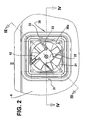
- the mounting arrangement of the fan 10 comprises a support frame 20, having a marginal portion 21 external to the contour of rotation of the propeller 12 and incorporating a central hub 22 in which is attached the electric motor 11.
- the marginal portion 21 of the support frame 20 presents the form of a tubular shell, with a circular internal contour and which is generally made of injected plastic material, incorporating the central hub 22 in a single piece through a centrally opened radial frame 23.
- said radial frame 23 is defined by a plurality of approximately radial rods interconnecting the central hub 22 to the marginal portion 21 in the form of a tubular shell circumferentially surrounding the propeller 12.
- the central hub 22 is preferably constructed in the form of a cylindrical tubular cup, dimensioned to receive the electric motor 11 therein and which defines a circular annular gap with the internal contour of the tubular shell.
- the mounting arrangement further comprises a flexible support 30, which is preferably obtained in a single piece of elastomeric material in the form of an annular flange and presents an outer portion 31, an inner portion 32, and an annular membrane portion 33 interconnecting the outer portion 31 and the inner portion 32.
- the outer portion 31 presents a polygonal or circular contour, which is compatible with that of the refrigerated air outlet 4b of the internal divisional wall 6, said outer portion 31 being designed to be peripherally and removably affixed to said internal divisional wall 6 along the contour of the refrigerated air outlet 4b.
- the outer portion 31 of the flexible support 30 is provided with a peripheral groove 34 to be fitted on an edge of the internal divisional wall 6 that defines the contour of the refrigerated air outlet 4b, allowing for an extremely simple, rapid and resistant assembly of the flexible support 30 to the internal divisional wall 6 of the refrigerator.
- the inner portion 32 of the flexible support 30 is provided with a generally circular central opening 35, and with retaining means 36, which are removably locked to the marginal portion 21 of the support frame 20 in a condition in which the marginal portion 21 is axially aligned with the central opening 35 of the flexible support 30.
- the retaining means 36 are defined by median axial projections of the inner portion 32 of the flexible support 30, said axial projections being fitted and retained, by the elastic deformation of respective widened heads 36a, into axial housings 24 provided in the marginal portion 21 of the support frame 20.
- the axial housings 24 may be defined as throughbores provided in a peripheral flange 25 of the marginal portion 21 of the support frame 20.
- the construction described above allows the flexible support 30 to be easily and rapidly adapted to the internal divisional wall 6, while the support frame 20, which carries the fan 10 and defines a protecting cowling that directs the airflow, is also easily assembled to and disassembled from the inner portion 32 of the flexible support 30.
- the annular membrane portion 33 is constructed with a thickness smaller than the remaining parts of the flexible support 30 and preferably with an arcuated profile in cross section, in order to allow small relative axial and radial displacements to occur between the outer portion 31 and the inner portion 32 of the flexible support 30, absorbing the vibrations caused during operation of the fan 10.
Landscapes
- Engineering & Computer Science (AREA)
- Mechanical Engineering (AREA)
- General Engineering & Computer Science (AREA)
- Chemical & Material Sciences (AREA)
- Combustion & Propulsion (AREA)
- Physics & Mathematics (AREA)
- Thermal Sciences (AREA)
- Power Engineering (AREA)
- Cold Air Circulating Systems And Constructional Details In Refrigerators (AREA)
- Structures Of Non-Positive Displacement Pumps (AREA)
Applications Claiming Priority (3)
| Application Number | Priority Date | Filing Date | Title |
|---|---|---|---|
| BRPI0201397-5A BR0201397B1 (pt) | 2002-04-19 | 2002-04-19 | arranjo de montagem para um ventilador de refrigerador. |
| BR0201397 | 2002-04-19 | ||
| PCT/BR2003/000059 WO2003089858A1 (en) | 2002-04-19 | 2003-04-16 | Mounting arrangement for a refrigerator fan |
Publications (2)
| Publication Number | Publication Date |
|---|---|
| EP1497600A1 EP1497600A1 (en) | 2005-01-19 |
| EP1497600B1 true EP1497600B1 (en) | 2008-01-09 |
Family
ID=29220359
Family Applications (1)
| Application Number | Title | Priority Date | Filing Date |
|---|---|---|---|
| EP03746788A Expired - Lifetime EP1497600B1 (en) | 2002-04-19 | 2003-04-16 | Mounting arrangement for a refrigerator fan |
Country Status (8)
| Country | Link |
|---|---|
| US (1) | US7317267B2 (pt) |
| EP (1) | EP1497600B1 (pt) |
| AR (1) | AR038318A1 (pt) |
| AU (1) | AU2003227144A1 (pt) |
| BR (1) | BR0201397B1 (pt) |
| DE (1) | DE60318566T2 (pt) |
| MX (1) | MXPA04010270A (pt) |
| WO (1) | WO2003089858A1 (pt) |
Families Citing this family (97)
| Publication number | Priority date | Publication date | Assignee | Title |
|---|---|---|---|---|
| EP1064382B1 (en) * | 1998-03-17 | 2008-08-20 | Genentech, Inc. | Polypeptides homologous to vegf and bmp1 |
| WO2005116455A1 (de) * | 2004-05-06 | 2005-12-08 | Thomson Licensing S.A. | Lüfterbefestigung |
| DE102004034472A1 (de) * | 2004-07-15 | 2006-02-09 | Spiess, Heike | Gedämpfter Lüfter |
| US7926099B1 (en) * | 2005-07-15 | 2011-04-12 | Novell, Inc. | Computer-implemented method and system for security event transport using a message bus |
| TWD125651S1 (zh) * | 2006-02-21 | 2008-10-21 | 日本電產股份有限公司 | 送風機 |
| TWD118870S1 (zh) * | 2006-09-12 | 2007-09-01 | 台達電子工業股份有限公司 | 散熱模組 |
| US7660115B2 (en) * | 2007-06-07 | 2010-02-09 | Hewlett-Packard Development Company, L.P. | Fan docking collar |
| GB0814835D0 (en) | 2007-09-04 | 2008-09-17 | Dyson Technology Ltd | A Fan |
| DE102008029913A1 (de) * | 2008-06-24 | 2009-12-31 | BSH Bosch und Siemens Hausgeräte GmbH | Wasserführendes Haushaltsgerät |
| GB2463698B (en) | 2008-09-23 | 2010-12-01 | Dyson Technology Ltd | A fan |
| GB2464736A (en) | 2008-10-25 | 2010-04-28 | Dyson Technology Ltd | Fan with a filter |
| GB2476171B (en) | 2009-03-04 | 2011-09-07 | Dyson Technology Ltd | Tilting fan stand |
| ATE512304T1 (de) | 2009-03-04 | 2011-06-15 | Dyson Technology Ltd | Gebläseanordnung |
| GB2468315A (en) | 2009-03-04 | 2010-09-08 | Dyson Technology Ltd | Tilting fan |
| GB2468312A (en) | 2009-03-04 | 2010-09-08 | Dyson Technology Ltd | Fan assembly |
| GB2468320C (en) | 2009-03-04 | 2011-06-01 | Dyson Technology Ltd | Tilting fan |
| KR101455224B1 (ko) | 2009-03-04 | 2014-10-31 | 다이슨 테크놀러지 리미티드 | 선풍기 |
| GB2468317A (en) * | 2009-03-04 | 2010-09-08 | Dyson Technology Ltd | Height adjustable and oscillating fan |
| GB2468331B (en) | 2009-03-04 | 2011-02-16 | Dyson Technology Ltd | A fan |
| GB2468323A (en) | 2009-03-04 | 2010-09-08 | Dyson Technology Ltd | Fan assembly |
| AU2010219489B2 (en) | 2009-03-04 | 2012-02-02 | Dyson Technology Limited | A fan |
| GB2468326A (en) | 2009-03-04 | 2010-09-08 | Dyson Technology Ltd | Telescopic pedestal fan |
| GB2468329A (en) | 2009-03-04 | 2010-09-08 | Dyson Technology Ltd | Fan assembly |
| AU2010220190B2 (en) | 2009-03-04 | 2012-11-15 | Dyson Technology Limited | Humidifying apparatus |
| GB0903682D0 (en) * | 2009-03-04 | 2009-04-15 | Dyson Technology Ltd | A fan |
| DE102009044349A1 (de) * | 2009-10-28 | 2011-05-05 | Minebea Co., Ltd. | Lüfteranordnung |
| GB0919473D0 (en) | 2009-11-06 | 2009-12-23 | Dyson Technology Ltd | A fan |
| GB2478925A (en) | 2010-03-23 | 2011-09-28 | Dyson Technology Ltd | External filter for a fan |
| GB2478927B (en) | 2010-03-23 | 2016-09-14 | Dyson Technology Ltd | Portable fan with filter unit |
| WO2011147318A1 (zh) | 2010-05-27 | 2011-12-01 | Li Dezheng | 借助窄缝喷嘴组件送风的装置 |
| GB2482548A (en) | 2010-08-06 | 2012-02-08 | Dyson Technology Ltd | A fan assembly with a heater |
| GB2482547A (en) | 2010-08-06 | 2012-02-08 | Dyson Technology Ltd | A fan assembly with a heater |
| GB2482549A (en) | 2010-08-06 | 2012-02-08 | Dyson Technology Ltd | A fan assembly with a heater |
| GB2483448B (en) * | 2010-09-07 | 2015-12-02 | Dyson Technology Ltd | A fan |
| WO2012049470A1 (en) | 2010-10-13 | 2012-04-19 | Dyson Technology Limited | A fan assembly |
| DK2630373T3 (en) | 2010-10-18 | 2017-04-10 | Dyson Technology Ltd | FAN UNIT |
| GB2484670B (en) | 2010-10-18 | 2018-04-25 | Dyson Technology Ltd | A fan assembly |
| US9926804B2 (en) | 2010-11-02 | 2018-03-27 | Dyson Technology Limited | Fan assembly |
| DE102010043246A1 (de) * | 2010-11-03 | 2012-05-03 | BSH Bosch und Siemens Hausgeräte GmbH | Kältegerät mit Ventilator |
| GB2486019B (en) | 2010-12-02 | 2013-02-20 | Dyson Technology Ltd | A fan |
| KR101595869B1 (ko) | 2011-07-27 | 2016-02-19 | 다이슨 테크놀러지 리미티드 | 팬 조립체 |
| GB2493506B (en) | 2011-07-27 | 2013-09-11 | Dyson Technology Ltd | A fan assembly |
| DE102011117087B4 (de) * | 2011-10-27 | 2018-10-18 | Volkswagen Aktiengesellschaft | Entkopplungselement und Anordnung zur schwingungsentkoppelnden Befestigung eines Funktionsmoduls an einem Fahrzeugteil sowie Verfahren zum Herstellen eines solchen |
| GB201119500D0 (en) | 2011-11-11 | 2011-12-21 | Dyson Technology Ltd | A fan assembly |
| GB2496877B (en) | 2011-11-24 | 2014-05-07 | Dyson Technology Ltd | A fan assembly |
| GB2498547B (en) | 2012-01-19 | 2015-02-18 | Dyson Technology Ltd | A fan |
| GB2499042A (en) | 2012-02-06 | 2013-08-07 | Dyson Technology Ltd | A nozzle for a fan assembly |
| GB2499041A (en) | 2012-02-06 | 2013-08-07 | Dyson Technology Ltd | Bladeless fan including an ionizer |
| GB2499044B (en) | 2012-02-06 | 2014-03-19 | Dyson Technology Ltd | A fan |
| GB2500012B (en) | 2012-03-06 | 2016-07-06 | Dyson Technology Ltd | A Humidifying Apparatus |
| GB2500011B (en) | 2012-03-06 | 2016-07-06 | Dyson Technology Ltd | A Humidifying Apparatus |
| GB2500017B (en) | 2012-03-06 | 2015-07-29 | Dyson Technology Ltd | A Humidifying Apparatus |
| SG11201405367VA (en) | 2012-03-06 | 2014-10-30 | Dyson Technology Ltd | A fan assembly |
| GB2512192B (en) | 2012-03-06 | 2015-08-05 | Dyson Technology Ltd | A Humidifying Apparatus |
| GB2500010B (en) | 2012-03-06 | 2016-08-24 | Dyson Technology Ltd | A humidifying apparatus |
| GB2500903B (en) | 2012-04-04 | 2015-06-24 | Dyson Technology Ltd | Heating apparatus |
| GB2501301B (en) | 2012-04-19 | 2016-02-03 | Dyson Technology Ltd | A fan assembly |
| CA2873302C (en) | 2012-05-16 | 2019-07-09 | Dyson Technology Limited | Air duct configuration for a bladeless fan |
| GB2532557B (en) | 2012-05-16 | 2017-01-11 | Dyson Technology Ltd | A fan comprsing means for suppressing noise |
| GB2518935B (en) | 2012-05-16 | 2016-01-27 | Dyson Technology Ltd | A fan |
| DE102012209199A1 (de) * | 2012-05-31 | 2013-12-05 | Robert Bosch Gmbh | Lüftersystem für ein Kühlsystem einer Brennkraftmaschine |
| GB2503907B (en) | 2012-07-11 | 2014-05-28 | Dyson Technology Ltd | A fan assembly |
| DE102012218347A1 (de) * | 2012-10-09 | 2014-05-15 | BSH Bosch und Siemens Hausgeräte GmbH | Lüftereinheit |
| PL2936011T3 (pl) * | 2012-12-24 | 2017-05-31 | Arçelik Anonim Sirketi | Układ do mocowania kasety wentylatora parownika dla lodówki |
| BR302013003358S1 (pt) | 2013-01-18 | 2014-11-25 | Dyson Technology Ltd | Configuração aplicada em umidificador |
| AU350181S (en) | 2013-01-18 | 2013-08-15 | Dyson Technology Ltd | Humidifier or fan |
| AU350140S (en) | 2013-01-18 | 2013-08-13 | Dyson Technology Ltd | Humidifier or fan |
| AU350179S (en) | 2013-01-18 | 2013-08-15 | Dyson Technology Ltd | Humidifier or fan |
| RU2672433C2 (ru) | 2013-01-29 | 2018-11-14 | Дайсон Текнолоджи Лимитед | Вентилятор в сборе |
| GB2510195B (en) | 2013-01-29 | 2016-04-27 | Dyson Technology Ltd | A fan assembly |
| CA152658S (en) | 2013-03-07 | 2014-05-20 | Dyson Technology Ltd | Fan |
| USD729372S1 (en) | 2013-03-07 | 2015-05-12 | Dyson Technology Limited | Fan |
| CA152655S (en) | 2013-03-07 | 2014-05-20 | Dyson Technology Ltd | Fan |
| CA152656S (en) | 2013-03-07 | 2014-05-20 | Dyson Technology Ltd | Fan |
| BR302013004394S1 (pt) | 2013-03-07 | 2014-12-02 | Dyson Technology Ltd | Configuração aplicada a ventilador |
| CA152657S (en) | 2013-03-07 | 2014-05-20 | Dyson Technology Ltd | Fan |
| EP2781919A1 (en) | 2013-03-19 | 2014-09-24 | Roche Diagniostics GmbH | Method / device for generating a corrected value of an analyte concentration in a sample of a body fluid |
| CN105899815B (zh) * | 2013-06-20 | 2018-07-03 | 阿塞里克股份有限公司 | 用于致冷设备的改进的风扇组件 |
| GB2530906B (en) | 2013-07-09 | 2017-05-10 | Dyson Technology Ltd | A fan assembly |
| TWD172707S (zh) | 2013-08-01 | 2015-12-21 | 戴森科技有限公司 | 風扇 |
| CA154723S (en) | 2013-08-01 | 2015-02-16 | Dyson Technology Ltd | Fan |
| CA154722S (en) | 2013-08-01 | 2015-02-16 | Dyson Technology Ltd | Fan |
| GB2518638B (en) | 2013-09-26 | 2016-10-12 | Dyson Technology Ltd | Humidifying apparatus |
| DE102013225651A1 (de) * | 2013-12-11 | 2015-06-11 | BSH Hausgeräte GmbH | Haushaltskältegerät mit einem Maschinenraum und einem an einem Querbalken des Maschinenraums montierten Ventilator-Gehäuse sowie Verfahren zur Montage eines derartigen Ventilators im Maschinenraum |
| KR101614586B1 (ko) * | 2013-12-23 | 2016-04-21 | 동부대우전자 주식회사 | 벽걸이 세탁기의 설치장치 |
| GB2528708B (en) | 2014-07-29 | 2016-06-29 | Dyson Technology Ltd | A fan assembly |
| GB2528704A (en) | 2014-07-29 | 2016-02-03 | Dyson Technology Ltd | Humidifying apparatus |
| GB2528709B (en) | 2014-07-29 | 2017-02-08 | Dyson Technology Ltd | Humidifying apparatus |
| US10101077B2 (en) * | 2014-09-25 | 2018-10-16 | Electrolux Home Products, Inc. | Fan mounting assembly, evaporator coil cover and air tower of refrigerator |
| US10254037B2 (en) | 2016-03-24 | 2019-04-09 | Electrolux Home Products, Inc. | Evaporator box fan mounting solution |
| KR101798574B1 (ko) * | 2016-05-02 | 2017-11-17 | 동부대우전자 주식회사 | 방열용 송풍기 및 이를 포함하는 냉장고 |
| JP2018076846A (ja) | 2016-11-11 | 2018-05-17 | 日本電産株式会社 | 軸流ファン、および冷蔵庫 |
| KR20180109311A (ko) * | 2017-03-27 | 2018-10-08 | 주식회사 대우전자 | 냉장고 및 냉장고용 팬 어셈블리 |
| CN207333306U (zh) * | 2017-06-20 | 2018-05-08 | 博西华电器(江苏)有限公司 | 冰箱及其风扇总成 |
| US10837461B2 (en) * | 2019-04-10 | 2020-11-17 | Haier Us Appliance Solutions, Inc. | Vibration isolating mounting of fan |
| SI26309A (sl) * | 2021-12-30 | 2023-07-31 | Gorenje Gospodinjski Aparati, D.O.O. | Hladilni in/ali zamrzovalni aparat |
| EP4653787A1 (en) | 2024-05-23 | 2025-11-26 | Arçelik Anonim Sirketi | A cooling device with a fan cover |
Family Cites Families (9)
| Publication number | Priority date | Publication date | Assignee | Title |
|---|---|---|---|---|
| GB883686A (en) * | 1958-04-01 | 1961-12-06 | Electrolux Ltd | Improvements in or relating to vacuum cleaners |
| US3584469A (en) * | 1969-11-24 | 1971-06-15 | Gen Motors Corp | Resilient mounting and support for electric motors and the like |
| US4568243A (en) * | 1981-10-08 | 1986-02-04 | Barry Wright Corporation | Vibration isolating seal for mounting fans and blowers |
| IL66917A0 (en) * | 1981-10-08 | 1982-12-31 | Wright Barry Corp | Vibration isolating seal device for mounting fans and blowers |
| DE8707975U1 (de) * | 1987-06-04 | 1988-09-29 | Siemens AG, 1000 Berlin und 8000 München | Befestigungsvorrichtung für einen Axiallüfter |
| DE3809627A1 (de) * | 1988-03-22 | 1989-10-05 | Semperit Ag Holding | Montagemodul fuer geblaese |
| JP3640815B2 (ja) * | 1998-11-05 | 2005-04-20 | 株式会社東芝 | ファン装置及び冷蔵庫 |
| US6351380B1 (en) * | 1999-11-12 | 2002-02-26 | Dell Products, L.P. | Cooling fan mounting arrangement |
| KR100404117B1 (ko) * | 2001-08-03 | 2003-11-03 | 엘지전자 주식회사 | 냉장고의 냉기 유동 발생구조 |
-
2002
- 2002-04-19 BR BRPI0201397-5A patent/BR0201397B1/pt not_active IP Right Cessation
-
2003
- 2003-01-28 AR ARP030100235A patent/AR038318A1/es active IP Right Grant
- 2003-04-16 AU AU2003227144A patent/AU2003227144A1/en not_active Abandoned
- 2003-04-16 US US10/507,979 patent/US7317267B2/en not_active Expired - Fee Related
- 2003-04-16 DE DE60318566T patent/DE60318566T2/de not_active Expired - Fee Related
- 2003-04-16 WO PCT/BR2003/000059 patent/WO2003089858A1/en not_active Ceased
- 2003-04-16 MX MXPA04010270A patent/MXPA04010270A/es active IP Right Grant
- 2003-04-16 EP EP03746788A patent/EP1497600B1/en not_active Expired - Lifetime
Also Published As
| Publication number | Publication date |
|---|---|
| BR0201397A (pt) | 2004-01-06 |
| US7317267B2 (en) | 2008-01-08 |
| EP1497600A1 (en) | 2005-01-19 |
| DE60318566T2 (de) | 2009-01-08 |
| WO2003089858A1 (en) | 2003-10-30 |
| DE60318566D1 (de) | 2008-02-21 |
| BR0201397B1 (pt) | 2011-10-18 |
| AR038318A1 (es) | 2005-01-12 |
| US20050173997A1 (en) | 2005-08-11 |
| MXPA04010270A (es) | 2005-02-03 |
| AU2003227144A1 (en) | 2003-11-03 |
Similar Documents
| Publication | Publication Date | Title |
|---|---|---|
| EP1497600B1 (en) | Mounting arrangement for a refrigerator fan | |
| EP3287707B1 (en) | Fan guard assembly and outdoor unit having the same | |
| US7363961B2 (en) | Heat exchanger support structure of motor vehicle and supporting method | |
| EP0921318B1 (en) | Fan assembly having motor cooling enhancement | |
| US5460485A (en) | Blower with an improved shroud assembly | |
| EP1361367B1 (en) | Turbo fan and air conditioner having the same applied thereto | |
| US5950446A (en) | Compact air conditioner | |
| JP5763090B2 (ja) | ガス供給調整装置、とりわけ呼吸補助装置 | |
| US12291078B2 (en) | Air conditioning unit | |
| EP2075472A2 (en) | Fan assembly | |
| EP0735252A2 (en) | Engine cooling system | |
| US7878772B2 (en) | Compressor assembly having an air-cooled electric motor | |
| KR20190062051A (ko) | 팬 조립체 및 이를 포함하는 냉장고 | |
| US6494681B2 (en) | Combined axial flow and centrifugal fan in an electrical motor | |
| KR101463812B1 (ko) | 냉장고의 팬모듈 | |
| WO2006137508A1 (en) | Air-cooled engine | |
| US5272886A (en) | Moisture disposing device for use in a self-contained air conditioner | |
| EP1416164A2 (en) | Two-piece molded fan | |
| GB2299158A (en) | Method and apparatus for securing a fan motor and heat exchanger to a structure | |
| KR200199703Y1 (ko) | 천정장착형 버스에어컨의 응축기 케이스 조립구조 | |
| CN222279006U (zh) | 嵌入式冰箱 | |
| CN220507161U (zh) | 风冷式冷水机组 | |
| WO2021190775A1 (en) | A refrigeration appliance equipped with a fan system | |
| CN215272221U (zh) | 主机和料理机 | |
| CN100380074C (zh) | 冰箱的送风装置 |
Legal Events
| Date | Code | Title | Description |
|---|---|---|---|
| PUAI | Public reference made under article 153(3) epc to a published international application that has entered the european phase |
Free format text: ORIGINAL CODE: 0009012 |
|
| 17P | Request for examination filed |
Effective date: 20041018 |
|
| AK | Designated contracting states |
Kind code of ref document: A1 Designated state(s): AT BE BG CH CY CZ DE DK EE ES FI FR GB GR HU IE IT LI LU MC NL PT RO SE SI SK TR |
|
| AX | Request for extension of the european patent |
Extension state: AL LT LV MK |
|
| GRAP | Despatch of communication of intention to grant a patent |
Free format text: ORIGINAL CODE: EPIDOSNIGR1 |
|
| GRAS | Grant fee paid |
Free format text: ORIGINAL CODE: EPIDOSNIGR3 |
|
| GRAA | (expected) grant |
Free format text: ORIGINAL CODE: 0009210 |
|
| AK | Designated contracting states |
Kind code of ref document: B1 Designated state(s): DE IT |
|
| REF | Corresponds to: |
Ref document number: 60318566 Country of ref document: DE Date of ref document: 20080221 Kind code of ref document: P |
|
| PLBE | No opposition filed within time limit |
Free format text: ORIGINAL CODE: 0009261 |
|
| STAA | Information on the status of an ep patent application or granted ep patent |
Free format text: STATUS: NO OPPOSITION FILED WITHIN TIME LIMIT |
|
| 26N | No opposition filed |
Effective date: 20081010 |
|
| PGFP | Annual fee paid to national office [announced via postgrant information from national office to epo] |
Ref country code: DE Payment date: 20090630 Year of fee payment: 7 |
|
| PGFP | Annual fee paid to national office [announced via postgrant information from national office to epo] |
Ref country code: IT Payment date: 20100427 Year of fee payment: 8 |
|
| PG25 | Lapsed in a contracting state [announced via postgrant information from national office to epo] |
Ref country code: DE Free format text: LAPSE BECAUSE OF NON-PAYMENT OF DUE FEES Effective date: 20101103 |
|
| PG25 | Lapsed in a contracting state [announced via postgrant information from national office to epo] |
Ref country code: IT Free format text: LAPSE BECAUSE OF NON-PAYMENT OF DUE FEES Effective date: 20110416 |