EP2075472A2 - Fan assembly - Google Patents
Fan assembly Download PDFInfo
- Publication number
- EP2075472A2 EP2075472A2 EP08170943A EP08170943A EP2075472A2 EP 2075472 A2 EP2075472 A2 EP 2075472A2 EP 08170943 A EP08170943 A EP 08170943A EP 08170943 A EP08170943 A EP 08170943A EP 2075472 A2 EP2075472 A2 EP 2075472A2
- Authority
- EP
- European Patent Office
- Prior art keywords
- shroud
- fan
- frame
- coupling
- fan assembly
- Prior art date
- Legal status (The legal status is an assumption and is not a legal conclusion. Google has not performed a legal analysis and makes no representation as to the accuracy of the status listed.)
- Granted
Links
- 230000008878 coupling Effects 0.000 claims abstract description 83
- 238000010168 coupling process Methods 0.000 claims abstract description 83
- 238000005859 coupling reaction Methods 0.000 claims abstract description 83
- 238000003780 insertion Methods 0.000 claims description 6
- 230000037431 insertion Effects 0.000 claims description 6
- 239000003507 refrigerant Substances 0.000 description 7
- 230000008901 benefit Effects 0.000 description 4
- 238000000034 method Methods 0.000 description 4
- 230000006835 compression Effects 0.000 description 3
- 238000007906 compression Methods 0.000 description 3
- 230000005494 condensation Effects 0.000 description 3
- 238000009833 condensation Methods 0.000 description 3
- 238000012986 modification Methods 0.000 description 3
- 230000004048 modification Effects 0.000 description 3
- 230000008569 process Effects 0.000 description 3
- 238000001816 cooling Methods 0.000 description 2
- 238000011144 upstream manufacturing Methods 0.000 description 2
- 230000001154 acute effect Effects 0.000 description 1
- 230000006978 adaptation Effects 0.000 description 1
- 238000001704 evaporation Methods 0.000 description 1
- 238000007710 freezing Methods 0.000 description 1
- 230000008014 freezing Effects 0.000 description 1
- 230000017525 heat dissipation Effects 0.000 description 1
- 238000010438 heat treatment Methods 0.000 description 1
- 238000009434 installation Methods 0.000 description 1
- 239000007788 liquid Substances 0.000 description 1
- 239000000463 material Substances 0.000 description 1
- 230000007246 mechanism Effects 0.000 description 1
- 238000005057 refrigeration Methods 0.000 description 1
- 238000007789 sealing Methods 0.000 description 1
- 239000003566 sealing material Substances 0.000 description 1
Images


Classifications
-
- F—MECHANICAL ENGINEERING; LIGHTING; HEATING; WEAPONS; BLASTING
- F25—REFRIGERATION OR COOLING; COMBINED HEATING AND REFRIGERATION SYSTEMS; HEAT PUMP SYSTEMS; MANUFACTURE OR STORAGE OF ICE; LIQUEFACTION SOLIDIFICATION OF GASES
- F25D—REFRIGERATORS; COLD ROOMS; ICE-BOXES; COOLING OR FREEZING APPARATUS NOT OTHERWISE PROVIDED FOR
- F25D19/00—Arrangement or mounting of refrigeration units with respect to devices or objects to be refrigerated, e.g. infrared detectors
-
- F—MECHANICAL ENGINEERING; LIGHTING; HEATING; WEAPONS; BLASTING
- F04—POSITIVE - DISPLACEMENT MACHINES FOR LIQUIDS; PUMPS FOR LIQUIDS OR ELASTIC FLUIDS
- F04D—NON-POSITIVE-DISPLACEMENT PUMPS
- F04D29/00—Details, component parts, or accessories
- F04D29/66—Combating cavitation, whirls, noise, vibration or the like; Balancing
- F04D29/661—Combating cavitation, whirls, noise, vibration or the like; Balancing especially adapted for elastic fluid pumps
- F04D29/668—Combating cavitation, whirls, noise, vibration or the like; Balancing especially adapted for elastic fluid pumps damping or preventing mechanical vibrations
-
- F—MECHANICAL ENGINEERING; LIGHTING; HEATING; WEAPONS; BLASTING
- F04—POSITIVE - DISPLACEMENT MACHINES FOR LIQUIDS; PUMPS FOR LIQUIDS OR ELASTIC FLUIDS
- F04D—NON-POSITIVE-DISPLACEMENT PUMPS
- F04D29/00—Details, component parts, or accessories
- F04D29/40—Casings; Connections of working fluid
- F04D29/52—Casings; Connections of working fluid for axial pumps
- F04D29/522—Casings; Connections of working fluid for axial pumps especially adapted for elastic fluid pumps
-
- F—MECHANICAL ENGINEERING; LIGHTING; HEATING; WEAPONS; BLASTING
- F04—POSITIVE - DISPLACEMENT MACHINES FOR LIQUIDS; PUMPS FOR LIQUIDS OR ELASTIC FLUIDS
- F04D—NON-POSITIVE-DISPLACEMENT PUMPS
- F04D29/00—Details, component parts, or accessories
- F04D29/60—Mounting; Assembling; Disassembling
- F04D29/64—Mounting; Assembling; Disassembling of axial pumps
- F04D29/644—Mounting; Assembling; Disassembling of axial pumps especially adapted for elastic fluid pumps
- F04D29/646—Mounting or removal of fans
-
- F—MECHANICAL ENGINEERING; LIGHTING; HEATING; WEAPONS; BLASTING
- F25—REFRIGERATION OR COOLING; COMBINED HEATING AND REFRIGERATION SYSTEMS; HEAT PUMP SYSTEMS; MANUFACTURE OR STORAGE OF ICE; LIQUEFACTION SOLIDIFICATION OF GASES
- F25D—REFRIGERATORS; COLD ROOMS; ICE-BOXES; COOLING OR FREEZING APPARATUS NOT OTHERWISE PROVIDED FOR
- F25D11/00—Self-contained movable devices, e.g. domestic refrigerators
-
- F—MECHANICAL ENGINEERING; LIGHTING; HEATING; WEAPONS; BLASTING
- F25—REFRIGERATION OR COOLING; COMBINED HEATING AND REFRIGERATION SYSTEMS; HEAT PUMP SYSTEMS; MANUFACTURE OR STORAGE OF ICE; LIQUEFACTION SOLIDIFICATION OF GASES
- F25D—REFRIGERATORS; COLD ROOMS; ICE-BOXES; COOLING OR FREEZING APPARATUS NOT OTHERWISE PROVIDED FOR
- F25D23/00—General constructional features
-
- F—MECHANICAL ENGINEERING; LIGHTING; HEATING; WEAPONS; BLASTING
- F25—REFRIGERATION OR COOLING; COMBINED HEATING AND REFRIGERATION SYSTEMS; HEAT PUMP SYSTEMS; MANUFACTURE OR STORAGE OF ICE; LIQUEFACTION SOLIDIFICATION OF GASES
- F25D—REFRIGERATORS; COLD ROOMS; ICE-BOXES; COOLING OR FREEZING APPARATUS NOT OTHERWISE PROVIDED FOR
- F25D2323/00—General constructional features not provided for in other groups of this subclass
- F25D2323/002—Details for cooling refrigerating machinery
- F25D2323/0028—Details for cooling refrigerating machinery characterised by the fans
- F25D2323/00281—Two or more fans
Definitions
- a refrigerator serves to store food with a low temperature in a frozen state or a cooled state according to the kind of food to be stored.
- Cool air is generated and is continuously supplied into the refrigerator as a refrigerant repeatedly performs a heat exchange operation, e.g., compression-condensation-expansion-evaporation.
- the cool air is uniformly transmitted through the inside of the refrigerator by convection, and serves to maintain food inside the refrigerator at a desired temperature.
- a refrigerating cycle device is provided at one side of the refrigerator separately from other storage spaces such as a cooling chamber and a freezing chamber. More particularly, compression and condensation processes are performed by a compressor and a condenser disposed at a machine room provided at a lower side of a rear surface of the refrigerator.
- a non-limiting feature of the present invention incudes providing coupling units that includes receiving portions downwardly opened and disposed at lower sides of the shroud, and configured to receive the vibration preventing members, and shroud coupling portions upwardly protruding from the planar surface of the apparatus adjacent the receiving portions.
- the vibration preventing members engage the receiving portions, and are coupled to the shroud coupling portions in a side direction.
- the receiving portions are configured such that each inlet width thereof is narrower than each outer diameter of the vibration preventing members.
- coupling holes are provided at the vibration preventing members and the shroud coupling portions receive coupling members configured to couple the vibration preventing members and the shroud coupling portions.
- the shroud is configured to fit to a shape of a longitudinal section of the apparatus, and a hermetic member is further provided on an outer edge of the shroud contacting an inner surface of the apparatus.
- a lower end of the shroud is coupled to the planar surface of the apparatus with a space provided therebetween.
- the present invention contemplates at least two coupling units are provided around the shroud ring at uniformly spaced intervals.
- the receiving portions are provided so that each inlet width thereof is narrower than each outer diameter of the vibration preventing members.
- fitting grooves are provided on outer side surfaces of the vibration preventing members and engage the receiving portions.
- the frame is configured to fit to a shape of a longitudinal section of the apparatus, and a hermetic member is further provided on at least an outer edge of the frame contacting an inner surface of the apparatus.
- the frame is integrally provided with the apparatus.
- the frame is fixedly coupled to frame coupling portions provided on a bottom surface of the apparatus.
- the frame coupling portions protrude from a bottom surface of the apparatus, and have angled end portions, and engage insertion portions provided at a lower side of the frame.
- the end portions of the frame coupling portions are elastically deformable.
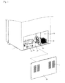
- FIG. 1 shows an inside of a machine room in a refrigerator according to a non-limiting embodiment of the present invention
- FIG. 2 is a rear perspective view of a fan coupled to a shroud according to a non-limiting embodiment of the present invention
- FIG. 3 is a perspective view showing a coupling assembly coupling the shroud to a surface of an apparatus according to a non-limiting embodiment of the present invention
- FIG. 5 is a longitudinal section view showing the fan, shroud, and coupling assembly according to a non-limiting embodiment of the present invention
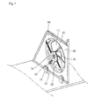
- FIG. 6 is an exploded view of a frame, a shroud, and a fan according to another non-limiting embodiment of the present invention.
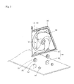
- FIG. 7 is a rear side view of the shroud of FIG. 6 ;
- FIG. 9 is a sectional view taken along line 'II-II' in FIG. 8 .
- the machine room 10 of the refrigerator 1 is disposed at a lower side of a rear surface of the refrigerator 1, and includes a compressor 40, a condenser 30, a refrigerant pipe 50, a fan 110 to dissipate heat from the compressor 40 and the condenser 30, and a shroud 120 having the fan 110 and a motor 130 mounted thereto.
- the interior of the machine room 10 is shielded by a machine room cover 20.
- the compressor 40 compresses a refrigerant into a gaseous refrigerant in high temperature and high pressure, and directs the gaseous refrigerant to the condenser 30.
- the machine room cover 20 shields the interior of the machine room 10 and is provided with air passing holes 21 through which external air is introduced into and discharged out of the refrigerator.
- the fan 110 may be configured as an axial fan linearly aligned with the compressor 40 and the condenser 30 such that heat can be effectively dissipated from the machine room 10.
- the fan 110 is mounted to the shroud 120 and provided in the machine room 10 between the compressor 40 and the condenser 30.
- the shroud 120 may be provided at an end side of the machine room 10 adjacent the condenser 30 in FIG. 1 .
- the fan 110 having a motor 130 coupled thereto is mounted to the shroud 120 for support, and the shroud 120 is coupled to a bottom surface of the apparatus by coupling units 140.
- Vibration preventing members 150 are disposed at the coupling units 140.
- the motor 130 may be configured as an outer rotor type motor.
- a stator is disposed inside a rotor, and the rotor is disposed within the fan 110.
- the motor 130 is mounted to a motor mounting portion 121 disposed at a central part of the opening 123, and the motor mounting portion 121 is supported by four motor supporting portions 122 extending therefrom; however, the present invention contemplates providing fewer or more motor supporting portions to support the motor mounting portion and the motor mounted thereto.
- the opening 123 is configured with a diameter so as to be adjacent with an outer radial edge of the fan 110.
- the diameter of the opening 123 is larger than a diameter of the radial edge of the fan 110 such that the fan 110 may be disposed within the diameter of the opening 123.
- An end portion of the opening 123 may be provided such that a concave surface of the end portion extends radially along the opening 123 in a downstream direction of the fan 110.
- air flowing in a downstream direction of the fan 110 is prevented from leaking in a radial direction of the fan 110, thereby preventing noise caused by air leakage.
- the coupling units 140 include receiving portions 141 disposed at lower sides of the shroud 120, and shroud coupling portions 142 that protrude from a bottom surface of the machine room 10 in correspondence to the receiving portions 141.
- Vibration preventing members 150 are disposed between the coupling units 140.
- the vibration preventing members 150 are further disposed within the receiving portions 141, and are coupled to the shroud coupling portions 142 in a side direction by coupling members 143.
- the vibration preventing members 150 are disposed between the receiving portions 141 and the shroud coupling portions 142, such that direct contact between the receiving portions 141 and the shroud coupling portions 142 is prevented. Accordingly, vibration and noise generated from the fan 110 and the shroud 120 are prevented from being transmitted to the apparatus via the shroud coupling portions 142, and absorbed by the vibration preventing members 150.
- the shroud 120 is provided so as to correspond to the shape of a longitudinal section of the apparatus. More specifically, the shroud 120 is configured so as to fit within the longitudinal section of the apparatus.
- the shroud 120 is coupled to the shroud coupling portion 142 such that the shroud 120 is spaced from the bottom surface of the machine room 10 by the hermetic member 160.
- a portion of the hermetic member 160 extending along the outer perimeter of the shroud 120 is provided in the space between the shroud 120 and the bottom surface of the apparatus to prevent air from passing therethrough.
- the shroud 220 includes a shroud ring 224 and is disposed such that the shroud ring 224 is adjacent to an outer circumferential surface of the fan 210.
- two protrusions 243 are provided; however, fewer or more protrusions are contemplated by the present invention.
- Vibration preventing members 250 are received by the receiving portions 241 along the radial direction of the shroud ring 224, and are coupled to the frame 270 in a side direction via the shroud coupling portion 242.
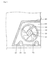
- FIG. 8 is a view of a fan assembly according to another non-limiting embodiment of the present invention, showing that the frame is coupled to the apparatus, and FIG. 9 is a sectional view taken along line 'II-II' in FIG. 8 .
- the hermetic member 260 prevents air from passing through gaps between the outer perimeter of the frame 270 and inner surfaces of the apparatus. Accordingly, air flows only through the shroud ring 224 accommodated in the opening 223, and thus the condenser 30 can dissipate heat more efficiently.
- the vibration preventing members are interposed between the coupling units of the shroud and the machine room. Therefore, the amount of vibration and noise transmitted from the fan and the motor to the apparatus can be reduced. That is, the vibration preventing members dampen (e.g., absorb) the vibration and reduce noise generation.
- the hermetic member is provided on the outer perimeter surface of the shroud, air generated by the fan flows only through the opening of the shroud. Accordingly, effectiveness of heat dissipation from the condenser and the compressor is enhanced, and the amount of vibration and noise transmitted to the apparatus through the outer perimeter of the shroud can be reduced.
Abstract
Description
- The present invention relates to a fan assembly, and more particularly, to a fan assembly to dissipate heat that may be included in a machine room of a refrigerator in which a compressor, a condenser, and the fan are also provided.
- Generally, a refrigerator serves to store food with a low temperature in a frozen state or a cooled state according to the kind of food to be stored.
- Cool air is generated and is continuously supplied into the refrigerator as a refrigerant repeatedly performs a heat exchange operation, e.g., compression-condensation-expansion-evaporation. The cool air is uniformly transmitted through the inside of the refrigerator by convection, and serves to maintain food inside the refrigerator at a desired temperature.
- A refrigerating cycle device is provided at one side of the refrigerator separately from other storage spaces such as a cooling chamber and a freezing chamber. More particularly, compression and condensation processes are performed by a compressor and a condenser disposed at a machine room provided at a lower side of a rear surface of the refrigerator.
- During the compression and condensation processes, heat must be dissipated. To this end, a fan and a motor configured to drive the fan are provided at the machine room to assist in dissipating the heat generated from the compression and condensation processes.
- However, when the motor is actuated and the fan is rotated within a shroud, vibration and noise are generated in the machine room. As a result, a user may be inconvenienced. Accordingly, a fan assembly configured to reduce vibration and noise generated from the motor and fan is required.
- Therefore, the present invention provides a fan assembly configured to reduce vibration and noise generated from a fan and a motor, and to efficiently dissipate heat, such as heat generated by a condenser and a compressor inside a machine room of a refrigerator.
- To achieve these and other features, and in accordance with the present invention, as embodied and broadly described herein, there is provided in a non-limiting embodiment, a fan assembly including a fan, a shroud comprising a motor mounting portion on which a fan motor of the fan is mounted, one or more coupling units provided at a lower side of the shroud, which couple the shroud to a planar surface of an apparatus, and one or more vibration preventing members interposed between the coupling units and the shroud. In some embodiments, the apparatus is a machine room of a refrigerator provided with a compressor and a condenser.
- A non-limiting feature of the present invention incudes providing coupling units that includes receiving portions downwardly opened and disposed at lower sides of the shroud, and configured to receive the vibration preventing members, and shroud coupling portions upwardly protruding from the planar surface of the apparatus adjacent the receiving portions.
- In embodiments, the vibration preventing members engage the receiving portions, and are coupled to the shroud coupling portions in a side direction.
- In embodiments, the receiving portions are configured such that each inlet width thereof is narrower than each outer diameter of the vibration preventing members.
- Another feature of the present invention provides fitting grooves provided on outer side surfaces of the vibration preventing members engaging the receiving portions.
- In embodiments, coupling holes are provided at the vibration preventing members and the shroud coupling portions receive coupling members configured to couple the vibration preventing members and the shroud coupling portions.
- In embodiments, the shroud is configured to fit to a shape of a longitudinal section of the apparatus, and a hermetic member is further provided on an outer edge of the shroud contacting an inner surface of the apparatus.
- In still other embodiments, a lower end of the shroud is coupled to the planar surface of the apparatus with a space provided therebetween.
- In yet another non-limiting embodiment, a fan assembly is provided and incudes a fan, a shroud comprising a motor mounting portion on which a fan motor of the fan is mounted, and a shroud ring disposed around the fan, a frame having the shroud mounted thereto, and coupled to an apparatus, one or more coupling units provided at the shroud and the frame, and configured to mount the shroud to the frame, and one or more vibration preventing members interposed between the coupling units. In embodiments, the apparatus is a machine room of a refrigerator provided with a compressor and a condenser.
- In embodiments, the frame may be provided with an opening configured to receive the shroud ring when the shroud is mounted thereto.
- In further embodiments, the coupling units include protrusions outwardly protruding from an outer circumference of the shroud ring in a radial direction, receiving portions provided at each end of the protrusions so as to be opened in the radial direction, and shroud coupling portions provided at the frame adjacent the receiving portions.
- In embodiments, the vibration preventing members engage the receiving portions, and are coupled to the frame in a side direction.
- Further, the present invention contemplates at least two coupling units are provided around the shroud ring at uniformly spaced intervals.
- In still other embodiments, the receiving portions are provided so that each inlet width thereof is narrower than each outer diameter of the vibration preventing members.
- In embodiments, fitting grooves are provided on outer side surfaces of the vibration preventing members and engage the receiving portions.
- According to another feature of the non-limiting embodiments, the frame is configured to fit to a shape of a longitudinal section of the apparatus, and a hermetic member is further provided on at least an outer edge of the frame contacting an inner surface of the apparatus.
- In embodiments, the frame is integrally provided with the apparatus.
- In alternative embodiments, the frame is fixedly coupled to frame coupling portions provided on a bottom surface of the apparatus.
- In embodiments, the frame coupling portions protrude from a bottom surface of the apparatus, and have angled end portions, and engage insertion portions provided at a lower side of the frame.
- In still further embodiments, the end portions of the frame coupling portions are elastically deformable.
- While the present invention is described herein as being used with refrigeration systems, it is not limited to such applications. In this regard, the present invention further contemplates use of the fan assembly in, but not limited to computer systems, HVAC systems, automotive applications, alone, and other known cooling and heating systems.
- The foregoing and other objects, features, aspects and advantages of the present invention will become more apparent from the following detailed description of the present invention when taken in conjunction with the accompanying drawings.
- The accompanying drawings, which are included to provide a further understanding of the present invention, are incorporated in and constitute a part of this specification. The drawings illustrate non-limiting embodiments of the present invention and together with the detailed description and appended claims serve to explain the principles of the present invention.
In the drawings: -
FIG. 1 shows an inside of a machine room in a refrigerator according to a non-limiting embodiment of the present invention; -
FIG. 2 is a rear perspective view of a fan coupled to a shroud according to a non-limiting embodiment of the present invention; -
FIG. 3 is a perspective view showing a coupling assembly coupling the shroud to a surface of an apparatus according to a non-limiting embodiment of the present invention; -
FIG. 4 is a front side view of a receiving portion and a vibration preventing member ofFIG. 3 according to a non-limiting embodiment of the present invention; -
FIG. 5 is a longitudinal section view showing the fan, shroud, and coupling assembly according to a non-limiting embodiment of the present invention; -
FIG. 6 is an exploded view of a frame, a shroud, and a fan according to another non-limiting embodiment of the present invention; -
FIG. 7 is a rear side view of the shroud ofFIG. 6 ; -
FIG. 8 is a perspective view of an alternative fan assembly according to yet another non-limiting, the fan assembly showing a frame fixed to a surface of an apparatus; and -
FIG. 9 is a sectional view taken along line 'II-II' inFIG. 8 . - Reference will now be made in detail to the non-limiting embodiments of the present invention, examples of which are illustrated in the accompanying drawings. Although some embodiments are illustrated herein, it should be understood that numerous other modifications and embodiments can be devised by those skilled in the art that will fall within the scope of the principles of the present invention.
- A fan assembly according to a first non-limiting embodiment of the present invention will now be explained in detail with reference to the attached drawings.
-
FIG. 1 shows inside of a machine room in a refrigerator 1 according to the first embodiment of the present invention. - Referring to
FIG. 1 , themachine room 10 of the refrigerator 1 is disposed at a lower side of a rear surface of the refrigerator 1, and includes acompressor 40, acondenser 30, arefrigerant pipe 50, afan 110 to dissipate heat from thecompressor 40 and thecondenser 30, and ashroud 120 having thefan 110 and amotor 130 mounted thereto. - The interior of the
machine room 10 is shielded by amachine room cover 20. - The
compressor 40 compresses a refrigerant into a gaseous refrigerant in high temperature and high pressure, and directs the gaseous refrigerant to thecondenser 30. - In order to prevent vibration and noise generated by the
compressor 40 during a heat exchange operation, vibration preventing members may be provided on an installation surface of thecompressor 40. - The
condenser 30 condenses the gaseous refrigerant in high temperature and high pressure from thecompressor 40 to a liquid refrigerant in low temperature and high pressure. - The machine room cover 20 shields the interior of the
machine room 10 and is provided withair passing holes 21 through which external air is introduced into and discharged out of the refrigerator. - The
fan 110 may be configured as an axial fan linearly aligned with thecompressor 40 and thecondenser 30 such that heat can be effectively dissipated from themachine room 10. In this regard, thefan 110 is mounted to theshroud 120 and provided in themachine room 10 between thecompressor 40 and thecondenser 30. However, theshroud 120 may be provided at an end side of themachine room 10 adjacent thecondenser 30 inFIG. 1 . - The
fan 110 and theshroud 120 will now be explained in detail with reference toFIGS. 2 to 4 . -
FIG. 2 is a rear perspective view of a surface of an apparatus, which shows thefan 110 coupled to theshroud 120.FIG. 3 is another perspective of the apparatus showing a coupling unit coupling theshroud 120 to thesurface 10 in the apparatus according to a non-limiting embodiment of the present invention.FIG. 4 is a front view of a receiving portion and a vibration preventing member of the coupling assembly ofFIG. 3 . - Referring to
FIG. 2 , thefan 110 having amotor 130 coupled thereto is mounted to theshroud 120 for support, and theshroud 120 is coupled to a bottom surface of the apparatus by couplingunits 140.Vibration preventing members 150 are disposed at thecoupling units 140. - In order to reduce the amount of space occupied by the
fan 110 and themotor 130 when coupled in an axial direction, themotor 130 may be configured as an outer rotor type motor. According to the outer rotor type motor, a stator is disposed inside a rotor, and the rotor is disposed within thefan 110. - The
motor 130 is mounted to and supported by theshroud 120. Theshroud 120 includes anopening 123 through which air generated by thefan 110 passes. - The
motor 130 is mounted to amotor mounting portion 121 disposed at a central part of theopening 123, and themotor mounting portion 121 is supported by fourmotor supporting portions 122 extending therefrom; however, the present invention contemplates providing fewer or more motor supporting portions to support the motor mounting portion and the motor mounted thereto. - The
opening 123 is configured with a diameter so as to be adjacent with an outer radial edge of thefan 110. The diameter of theopening 123 is larger than a diameter of the radial edge of thefan 110 such that thefan 110 may be disposed within the diameter of theopening 123. - An end portion of the
opening 123 may be provided such that a concave surface of the end portion extends radially along theopening 123 in a downstream direction of thefan 110. - Accordingly, air flowing in a downstream direction of the
fan 110 is prevented from leaking in a radial direction of thefan 110, thereby preventing noise caused by air leakage. - Referring to
FIG. 3 , thecoupling units 140 include receivingportions 141 disposed at lower sides of theshroud 120, andshroud coupling portions 142 that protrude from a bottom surface of themachine room 10 in correspondence to the receivingportions 141. - The receiving
portions 141 are provided at lower ends of theshroud 120, and are downwardly opened and may be configured as arcuate slots, or any other suitable shape to couple with a complimentary structure. - In order to stably couple the
shroud 120 to themachine room 10, two receivingportions 141 are provided; however fewer or more receiving portions may be provided for additional stability of the shroud and related components. - The
shroud coupling portions 142 protrude from the bottom surface of the apparatus in correspondence to the receivingportions 141. Theshroud coupling portions 142 may be rectangular in shape (although other suitable shapes are contemplated by the present invention). Coupling holes (not labeled) may be provided at a central part of theshroud coupling portions 142. The coupling holes are linearly aligned along a central axis in the axial direction of the receivingportion 141, theshroud coupling portion 142, and thecoupling member 143. -
Vibration preventing members 150 are disposed between thecoupling units 140. Thevibration preventing members 150 are further disposed within the receivingportions 141, and are coupled to theshroud coupling portions 142 in a side direction by couplingmembers 143. - The
vibration preventing members 150 are disposed between the receivingportions 141 and theshroud coupling portions 142, such that direct contact between the receivingportions 141 and theshroud coupling portions 142 is prevented. Accordingly, vibration and noise generated from thefan 110 and theshroud 120 are prevented from being transmitted to the apparatus via theshroud coupling portions 142, and absorbed by thevibration preventing members 150. - In order to allow the
fan 110 to be easily replaced, repaired, etc. thecoupling members 143 may be configured as bolts or pins that can be easily detachably mounted, or any other suitable removable fastener. - The
vibration preventing members 150 are cylindrical in shape, although other suitable shapes are contemplated by the present invention, and anaperture 152 extends through a central part therethrough creating an inner diameter (d2) and an outer diameter (d1). Thevibration preventing members 150 may be made of rubber or any suitable material known to absorb and dampen vibrations and/or noise. Fittinggrooves 151 are provided along a central part of the outer diameter (d1) in a circumferential direction such that thefitting grooves 151 mate with receivingportions 141 at an inner arcuate surface of the arcuate slot. Thefitting grooves 151 mated with the receivingportions 141 prevent thevibration preventing members 150 from moving in a thickness direction. - Referring to
FIG. 4 , each of the receivingportions 141 is provided such that an inlet width (W) thereof may be narrower than each outer diameter (d1) of thevibration preventing members 150. The inlet width is configured to receive thevibration preventing member 150 via thefitting groove 151. - A curvature radius (R) of the inner arcuate surface of each of the receiving
portions 141 is configured to be smaller than 1/2 of each outer diameter (d1) of thevibration preventing members 150, and is configured to be equal to or smaller than 1/2 of the diameter (d2) of thefitting groove 151. - Accordingly, the
vibration preventing members 150 are prevented from rotating along the inner arcuate surface of the receivingportions 141. - An engagement between an outer surface of the
shroud 120 and the bottom surface of the apparatus will now be explained in detail with reference toFIG. 5 . -
FIG. 5 is a longitudinal section view of the shroud and the coupling assembly in the apparatus according to the first non-limiting embodiment of the present invention; - Referring to
FIG. 5 , theshroud 120 is provided so as to correspond to the shape of a longitudinal section of the apparatus. More specifically, theshroud 120 is configured so as to fit within the longitudinal section of the apparatus. - A
hermetic member 160 is further provided on an outer perimeter of theshroud 120 and contacts inner surfaces of the apparatus. - The
hermetic member 160 may be configured as an elastic member such as a sponge or a rubber liner, although other sealing mechanisms are contemplated by the present invention. - The
hermetic member 160, prevents air from passing through gaps between the outer perimeter of theshroud 120 and the inner surfaces of themachine room 10. Accordingly, air flows only through theopening 123, and thus thecondenser 30 can dissipate heat more efficiently. - Additionally, vibration generated by the operation of the
motor 130 and rotation of thefan 110 at theshroud 120 is prevented from being transmitted to themachine room 10. - The
shroud 120 is coupled to theshroud coupling portion 142 such that theshroud 120 is spaced from the bottom surface of themachine room 10 by thehermetic member 160. In this regard, a portion of thehermetic member 160 extending along the outer perimeter of theshroud 120 is provided in the space between theshroud 120 and the bottom surface of the apparatus to prevent air from passing therethrough. - A fan assembly according to a second non-limiting embodiment of the present invention will now be explained in detail with reference to the attached drawings. Wherein the configuration and the description of the second non-limiting embodiment is the same as that of the first non-limiting embodiment, discussion of the same may be omitted (e.g.
vibration preventing member 250 corresponds to thevibration preventing member 150 described and shown in the first non-limiting embodiment). - More specifically,
FIGS. 6 and7 provide a fan that may be installed in an apparatus according to the second non-limiting embodiment of the present invention.FIG. 6 is an exploded view of aframe 270, ashroud 220, and afan 210 ,andFIG. 7 is a rear view of the shroud ofFIG. 6 . - Referring to
FIGS. 6 and7 , thefan 210 coupled to amotor 230 may be provided in the apparatus so as to dissipate heat from thecompressor 40 and thecondenser 30. - The
motor 230 is mounted to amotor mounting portion 221 of theshroud 220, and themotor mounting portion 221 is connected to theshroud 220 by a plurality ofmotor supporting portions 222. - Accordingly, the
motor 230 is mounted to and supported by theshroud 220. - The
shroud 220 includes ashroud ring 224 and is disposed such that theshroud ring 224 is adjacent to an outer circumferential surface of thefan 210. - The
shroud ring 224 is provided in a ring shape having a certain width in a radial direction of thefan 210 such that the flow of air generated by thefan 210 is guided therethrough. - The
shroud ring 224 protrudes in an upstream direction of thefan 210, and is configured with a concave surface in a downstream direction of thefan 210. - Accordingly, air passing through the
shroud ring 224 is prevented from leaking in a radial direction of thefan 210, and the amount of noise caused by air leakage can be reduced. - The
shroud 220 is coupled to theframe 270 and theframe 270 is fixed to the apparatus surface viaframe coupling portions 271. - The
shroud 220 and theframe 270 are provided withcoupling units 240 for coupling therebetween, respectively. -
Vibration preventing members 250 configured to prevent vibration and noise (generated by the operation of themotor 230 and the rotation of the fan 210) from being transmitted to the apparatus through theframe 270 are interposed between thecoupling units 240. - In order to allow air generated by the
fan 210 to flow only through theshroud ring 224, theframe 270 is provided with anopening 223 corresponding to a diameter of theshroud ring 224. Here, theshroud ring 224 is accommodated in theopening 223. - In correspondence to the shape of the
shroud ring 224, an end portion of theopening 223 protrude in the upstream direction of thefan 210, and has the concave surface in the downstream direction of thefan 210. - The
coupling units 240 includeprotrusions 243 outwardly protruding from an outer circumference of theshroud ring 224 in a radial direction, receivingportions 241 having an arcuate surface are provided at the end of theprotrusions 243 so as to be opened in the protruding direction, andshroud coupling portions 242 provided at theframe 270 in correspondence to the receivingportions 241. - In order to prevent the
shroud 220 coupled to theframe 270 from moving, twoprotrusions 243 are provided; however, fewer or more protrusions are contemplated by the present invention. - The
protrusions 243 are provided at an outer edge of theshroud ring 224 extending in the radial direction with a constant angle therebetween. - More specifically, as shown in
FIG. 7 , theprotrusions 243 are provided so that angles therebetween of α, β, and γ can be equal to each other to uniformly distribute vibration generated by operation of themotor 230 and rotation of thefan 210. -
Vibration preventing members 250 are received by the receivingportions 241 along the radial direction of theshroud ring 224, and are coupled to theframe 270 in a side direction via theshroud coupling portion 242. - The receiving
portions 241 are provided such that each inlet width (W) thereof can be narrower than each outer diameter (d1) of the vibration preventing members 250 (having the same configuration as the vibration preventing members described in the first non-limiting embodiment). - Fitting
grooves 251 fitted into the receivingportions 241 extend along the outer circumferential surfaces of thevibration preventing members 250. Thefitting grooves 251 prevent thevibration preventing members 250 fitted into the receivingportions 241 from moving in a thickness direction (i.e., an axial direction). - Coupling
holes 252 are provided through a central part of thevibration preventing members 250 in the thickness direction. - Coupling
members 244 for coupling theshroud 220 and theframe 270 to each other are provided to penetrate the coupling holes 252. Thecoupling members 244 are coupled to theshroud coupling portions 242 provided on the rear surface of theframe 270 in correspondence to theprotrusions 243. - Coupling of the
frame 270 to the bottom surface of themachine room 10 will now be explained in detail with reference toFIGS. 8 and9 . -
FIG. 8 is a view of a fan assembly according to another non-limiting embodiment of the present invention, showing that the frame is coupled to the apparatus, andFIG. 9 is a sectional view taken along line 'II-II' inFIG. 8 . - Referring to
FIGS. 8 and9 , theframe 270 is provided so as to correspond to a shape of a longitudinal section of the apparatus. - A
hermetic member 260 is further provided on an outer perimeter of theframe 270 and contacts inner surfaces of the apparatus. The hermetic member may be made of a sponge or rubber liner, or any other suitable sealing material. - The
hermetic member 260 prevents air from passing through gaps between the outer perimeter of theframe 270 and inner surfaces of the apparatus. Accordingly, air flows only through theshroud ring 224 accommodated in theopening 223, and thus thecondenser 30 can dissipate heat more efficiently. - Additionally, vibration of the
frame 270 that would otherwise be transmitted to the inner surfaces of the apparatus due to vibration of themotor 230 andfan 210 is prevented. - The
frame 270 is fixedly coupled toframe coupling portions 271 provided on a bottom surface of the apparatus. - The
frame coupling portions 271 protrude from a bottom surface of the apparatus.Insertion portions 272 configured to mate with theframe coupling portions 271 are provided at a lower side of theframe 270 parallel to the bottom surface of the apparatus. Theframe coupling portions 271 further include a locking protrusion (that is also provided parallel to the bottom surface of the apparatus) that engages theinsertion portions 272. The locking protrusion includes an elastically deformable locking arm that extends at an acute angle from an upper surface of the locking protrusion such that it may be inserted through theinsertion portions 272. That is, when theframe coupling portions 271 are inserted through theinsertion portions 272, the locking arm abuts a surface at the lower side of theframe 270 such that theframe coupling portion 271 cannot be easily disengaged from theframe 270. - The
frame 270 may be integrally provided on a bottom surface of the apparatus. However, the former case is more preferable than the latter case in the aspect of assembly efficiency of theshroud 220 to theframe 270. - The number of the
frame coupling portions 271 may be varied so that theframe 270 can be stably fixed to a bottom surface of the apparatus. - The fan assembly according to the first non-limiting embodiment of the present invention has the following advantages.
- First, because the fan and the motor cause vibration and noise, because the fan and motor are mounted to the shroud, and because the shroud is fixed to the apparatus, the vibration preventing members are interposed between the coupling units of the shroud and the machine room. Therefore, the amount of vibration and noise transmitted from the fan and the motor to the apparatus can be reduced. That is, the vibration preventing members dampen (e.g., absorb) the vibration and reduce noise generation.
- Second, since the hermetic member is provided on the outer perimeter surface of the shroud, air generated by the fan flows only through the opening of the shroud. Accordingly, effectiveness of heat dissipation from the condenser and the compressor is enhanced, and the amount of vibration and noise transmitted to the apparatus through the outer perimeter of the shroud can be reduced.
- The fan assembly according to another aspect of the present invention has the following advantage.
- Because the fan and the motor mounted to the shroud causes vibration and noise, because the shroud is coupled to the frame, and because the frame is fixed to the apparatus, the vibration preventing members are interposed between the shroud and the frame to reduce the amount of vibration and noise transmitted to the machine room from the fan and the motor.
- The foregoing embodiments and advantages are merely exemplary and are not to be construed as limiting the present invention. The present teachings can be readily applied to other types of apparatuses. This description is intended to be illustrative, and not to limit the scope of the claims. Many alternatives, modifications, and variations will be apparent to those skilled in the art. The features, structures, methods, and other characteristics of the exemplary embodiments described herein may be combined in various ways to obtain additional and/or alternative exemplary embodiments.
- As the present features may be embodied in several forms without departing from the characteristics thereof, it should also be understood that the above-described embodiments are not limited by any of the details of the foregoing description, unless otherwise specified, but rather should be construed broadly within its scope as defined in the appended claims, and therefore all changes and modifications that fall within the metes and bounds of the claims, or equivalents of such metes and bounds are therefore intended to be embraced by the appended claims.
- One or more embodiments of the disclosure may be referred to herein, individually and/or collectively, by the term "invention" merely for convenience and without intending to voluntarily limit the scope of this application to any particular invention or inventive concept. Moreover, although specific embodiments have been illustrated and described herein, it should be appreciated that any subsequent arrangement designed to achieve the same or similar purpose may be substituted for the specific embodiments shown. This disclosure is intended to cover any and all subsequent adaptations or variations of various embodiments. Combinations of the above embodiments, and other embodiments not specifically described herein, will be apparent to those of skill in the art upon reviewing the description.
Claims (15)
- A fan assembly, comprising:a fan;a shroud comprising a motor mounting portion on which a fan motor of the fan is mounted;one or more coupling units provided at a lower side of the shroud, which couple the shroud to a planar surface of an apparatus; andone or more vibration preventing members interposed between the coupling units and the shroud.
- The fan assembly of claim 1, wherein the coupling units comprise:receiving portions downwardly opened and disposed at the lower side of the shroud, and configured to receive the vibration preventing members; andshroud coupling portions upwardly protruding from the planar surface of the apparatus adjacent the receiving portions.
- The fan assembly of claim 2, wherein the vibration preventing members engage the receiving portions, and are coupled to the shroud coupling portions in a side direction.
- The fan assembly of claim 2 or 3, wherein the receiving portions are configured such that each inlet width thereof is narrower than each outer diameter of the vibration preventing members.
- The fan assembly of claim 2, 3 or 4, wherein coupling holes provided at the vibration preventing members and the shroud coupling portions receive coupling members configured to couple the vibration preventing members and the shroud coupling portions.
- The fan assembly of any of claims 1 to 5, wherein the shroud is configured to fit to a shape of a longitudinal section of the apparatus, and a hermetic member is further provided on an outer edge of the shroud contacting an inner surface of the apparatus.
- The fan assembly of any of claims 1 to 6, wherein a lower end of the shroud is coupled to the planar surface of the apparatus with a space provided therebetween.
- The fan assembly of any of claims 1 to 7, wherein the apparatus is a machine room of a refrigerator provided with a compressor and a condenser.
- A fan assembly, comprising:a fan;a shroud comprising a motor mounting portion on which a fan motor of the fan is mounted, and a shroud ring disposed around the fan;a frame having the shroud mounted thereto, and coupled to an apparatus;one or mare coupling units provided at the shroud and the frame, and configured to mount the shroud to the frame; andone or more vibration preventing members interposed between the coupling units.
- The fan assembly of claim 9, wherein the coupling units comprise:protrusions outwardly protruding from an outer circumference of the shroud ring in a radial direction;receiving portions provided at each end of the protrusions so as to be opened in the radial direction; andshroud coupling portions provided at the frame adjacent the receiving portions.
- The fan assembly of claim 10, wherein the vibration preventing members engage the receiving portions, and are coupled to the frame in a side direction.
- The fan assembly of claim 10 or 11, wherein the frame is configured to fit to a shape of a longitudinal section of the apparatus, and a hermetic member is further provided on at least an outer edge of the frame contacting an inner surface of the apparatus.
- The fan assembly of claim 10, 11 or 12, wherein the frame is fixedly coupled to frame coupling portions provided on a bottom surface of the apparatus.
- The fan assembly of claim 13, wherein the frame coupling portions protrude from the bottom surface of the apparatus, and have angled end portions, and engage insertion portions provided at a lower side of the frame.
- The fan assembly of any of claims 10 to 14, wherein the apparatus is a machine room of a refrigerator provided with a compressor and a condenser.
Applications Claiming Priority (1)
| Application Number | Priority Date | Filing Date | Title |
|---|---|---|---|
| KR1020070140932A KR101427269B1 (en) | 2007-12-28 | 2007-12-28 | Refrigerator |
Publications (3)
| Publication Number | Publication Date |
|---|---|
| EP2075472A2 true EP2075472A2 (en) | 2009-07-01 |
| EP2075472A3 EP2075472A3 (en) | 2017-02-22 |
| EP2075472B1 EP2075472B1 (en) | 2020-06-17 |
Family
ID=40445889
Family Applications (1)
| Application Number | Title | Priority Date | Filing Date |
|---|---|---|---|
| EP08170943.8A Active EP2075472B1 (en) | 2007-12-28 | 2008-12-08 | Fan assembly |
Country Status (4)
| Country | Link |
|---|---|
| US (1) | US8337155B2 (en) |
| EP (1) | EP2075472B1 (en) |
| KR (1) | KR101427269B1 (en) |
| CN (1) | CN101469723B (en) |
Cited By (5)
| Publication number | Priority date | Publication date | Assignee | Title |
|---|---|---|---|---|
| TWI395877B (en) * | 2009-11-11 | 2013-05-11 | Yen Sun Technology Corp | Shock absorber |
| TWI395876B (en) * | 2009-10-20 | 2013-05-11 | Yen Sun Technology Corp | Can absorb the vibration of the fan |
| US9496767B2 (en) | 2013-11-29 | 2016-11-15 | Sunonwealth Electric Machine Industry Co., Ltd. | Motor and motor vibration-proof mechanism thereof |
| WO2018192758A1 (en) * | 2017-04-18 | 2018-10-25 | BSH Hausgeräte GmbH | Refrigeration device comprising a damping disc |
| EP3511593A1 (en) * | 2018-01-12 | 2019-07-17 | Yen Sun Technology Corp. | Fan |
Families Citing this family (27)
| Publication number | Priority date | Publication date | Assignee | Title |
|---|---|---|---|---|
| KR20110019074A (en) * | 2009-08-19 | 2011-02-25 | 엘지전자 주식회사 | A refrigerator |
| KR101660720B1 (en) * | 2009-08-24 | 2016-09-28 | 엘지전자 주식회사 | A refrigerator |
| KR101897728B1 (en) * | 2011-09-15 | 2018-09-12 | 엘지전자 주식회사 | A cooling apparatus for a refrigerator machine room using nacelle shape |
| TWI504808B (en) * | 2012-05-15 | 2015-10-21 | Delta Electronics Inc | Vibration fan |
| DE102012218347A1 (en) | 2012-10-09 | 2014-05-15 | BSH Bosch und Siemens Hausgeräte GmbH | fan unit |
| CN103335196A (en) * | 2013-07-09 | 2013-10-02 | 樊书印 | Miniature fan |
| CN104344639B (en) * | 2013-10-18 | 2017-02-08 | 海尔集团公司 | Draught fan fixing structure |
| KR102168586B1 (en) * | 2013-11-29 | 2020-10-22 | 삼성전자주식회사 | Refrigerator |
| US20150233388A1 (en) * | 2014-02-18 | 2015-08-20 | Ciena Corporation | Telecommunications system cooling fan incorporating a compact vibration isolator |
| EP2993427B1 (en) * | 2014-09-05 | 2018-03-21 | Samsung Electronics Co., Ltd. | Refrigerator |
| US20160116204A1 (en) * | 2014-10-22 | 2016-04-28 | General Electric Company | Fan with integrated plenum |
| CN104564848A (en) * | 2014-12-30 | 2015-04-29 | 合肥晶弘电器有限公司 | Fan denoising structure and refrigerator |
| CN107023499B (en) * | 2016-01-29 | 2020-04-24 | 台达电子工业股份有限公司 | Fan and heat dissipation device |
| KR101798574B1 (en) * | 2016-05-02 | 2017-11-17 | 동부대우전자 주식회사 | Radiation blower and refrigerator comprising the same |
| TR201607826A2 (en) * | 2016-06-09 | 2017-12-21 | Arcelik As | REFRIGERATOR WITH A FAN ASSEMBLY |
| KR101878072B1 (en) * | 2016-10-26 | 2018-07-12 | 엘지전자 주식회사 | A mounting structure of compressor to refrigerator and a mounting method thereof |
| KR20180109311A (en) * | 2017-03-27 | 2018-10-08 | 주식회사 대우전자 | Refrigerator and fan assembly for refrigerator |
| KR101976291B1 (en) * | 2017-12-13 | 2019-05-07 | 엘지전자 주식회사 | A tray drip fir compact machine compartment and a refrigerator using the same |
| KR102004047B1 (en) | 2017-10-23 | 2019-07-25 | 엘지전자 주식회사 | A tray drip fir compact machine compartment and a refrigerator using the same |
| CN207963280U (en) * | 2017-11-27 | 2018-10-12 | 博西华电器(江苏)有限公司 | Refrigerator |
| CN108180174B (en) * | 2018-01-23 | 2019-01-08 | 温州捷高科技有限公司 | A kind of electric car fan shield |
| JP6988615B2 (en) * | 2018-03-20 | 2022-01-05 | 株式会社デンソー | Electric pump mounting structure |
| US10801771B2 (en) * | 2018-05-14 | 2020-10-13 | Heatcraft Refrigeration Products Llc | Condenser fan motor mounts and guards |
| US11268538B2 (en) * | 2019-04-03 | 2022-03-08 | Dell Products L.P. | Multiple function fan holder |
| US11624543B2 (en) * | 2019-08-26 | 2023-04-11 | Lg Electronics Inc. | Under counter type refrigerator |
| CN113357178A (en) * | 2021-07-13 | 2021-09-07 | 阳光电源股份有限公司 | Fan assembly and inverter |
| TWI822397B (en) * | 2022-10-18 | 2023-11-11 | 元山科技工業股份有限公司 | Vibration reduction frame of axial flow cooling fan |
Family Cites Families (29)
| Publication number | Priority date | Publication date | Assignee | Title |
|---|---|---|---|---|
| US2451970A (en) * | 1945-03-03 | 1948-10-19 | Vornado Trust | Mounting for fan assemblies |
| DE1428037A1 (en) * | 1964-05-16 | 1968-11-28 | Bahco Ab | Fan with vibration-absorbing suspension |
| US3714795A (en) * | 1970-03-31 | 1973-02-06 | Tappan Co | Outdoor refrigerant apparatus |
| US3773285A (en) * | 1972-02-18 | 1973-11-20 | W Morrill | Flexible machine mounting |
| US4036292A (en) * | 1975-10-21 | 1977-07-19 | Westinghouse Electric Corporation | Refrigeration condenser |
| GB2234012A (en) | 1989-07-14 | 1991-01-23 | Ibm | Dc motor driven centrifugal fan |
| DE8908987U1 (en) * | 1989-07-25 | 1989-11-02 | Neuhaus, Gerhard, Dipl.-Ing., 6301 Fernwald, De | |
| DE4238895C1 (en) * | 1992-11-19 | 1993-12-16 | Howatherm Klimatech Gmbh | Electric ventilation fan for air-conditioning duct - has peripheral seal for suction plate and vibration damping of fan motor mounting, to reduce noise |
| KR0128829Y1 (en) * | 1993-05-29 | 1999-01-15 | 구자홍 | Mounting device of wind-fan of outdoor of an airconditioner |
| JP3487382B2 (en) * | 1994-12-28 | 2004-01-19 | 株式会社デンソー | Boiling cooling device |
| JP3705697B2 (en) * | 1998-07-10 | 2005-10-12 | 株式会社東芝 | Fan device |
| US20020088237A1 (en) * | 1999-10-05 | 2002-07-11 | Rudick Arthur G. | Apparatus using vibrationally isolating stirling cooler system |
| CN2472459Y (en) | 2001-01-16 | 2002-01-16 | 联想(北京)有限公司 | Shell fan fixer without screw nails |
| CN1239872C (en) * | 2001-05-09 | 2006-02-01 | 株式会社日立制作所 | Refrigerator |
| KR100827779B1 (en) * | 2002-08-08 | 2008-05-07 | 엘지전자 주식회사 | Support structure for fan motor of refrigerator |
| KR100471444B1 (en) * | 2002-08-14 | 2005-03-08 | 엘지전자 주식회사 | The axial flow fan with turbo blades |
| KR100484828B1 (en) * | 2002-11-27 | 2005-04-22 | 엘지전자 주식회사 | Refrigerator's cool air circulation axial flow fan |
| KR100547328B1 (en) * | 2003-09-05 | 2006-01-26 | 엘지전자 주식회사 | The fan of air-conditioner outdoor unit |
| KR100569891B1 (en) * | 2003-12-18 | 2006-04-10 | 엘지전자 주식회사 | Method for control operation of pan in refrigerator |
| US6980435B2 (en) * | 2004-01-28 | 2005-12-27 | Hewlett-Packard Development Company, L.P. | Modular electronic enclosure with cooling design |
| JP2005214617A (en) * | 2004-01-28 | 2005-08-11 | Lg Electronics Inc | Refrigerator having cross flow fan |
| US7342789B2 (en) * | 2005-06-30 | 2008-03-11 | International Business Machines Corporation | Method and apparatus for cooling an equipment enclosure through closed-loop, liquid-assisted air cooling in combination with direct liquid cooling |
| TWI322230B (en) * | 2005-06-30 | 2010-03-21 | Delta Electronics Inc | Fan module and its fan casing |
| KR100737982B1 (en) * | 2005-07-12 | 2007-07-13 | 삼성광주전자 주식회사 | Hermetic type compressor |
| JP4618077B2 (en) | 2005-09-27 | 2011-01-26 | 株式会社デンソー | Cooling fan and blower |
| CN101022196A (en) | 2006-02-15 | 2007-08-22 | 鸿富锦精密工业(深圳)有限公司 | Fan power supply switching device |
| US7488152B2 (en) * | 2006-04-10 | 2009-02-10 | Super Micro Computer, Inc. | Vibration absorption device for a fan |
| KR100713122B1 (en) | 2006-06-13 | 2007-05-02 | 위니아만도 주식회사 | Combination structure of fan motor which is used in condenser |
| TWM313415U (en) * | 2006-12-07 | 2007-06-01 | Inventec Corp | Fixing mechanism for fan frame use |
-
2007
- 2007-12-28 KR KR1020070140932A patent/KR101427269B1/en active IP Right Grant
-
2008
- 2008-12-03 US US12/327,039 patent/US8337155B2/en active Active
- 2008-12-08 EP EP08170943.8A patent/EP2075472B1/en active Active
- 2008-12-26 CN CN2008101906395A patent/CN101469723B/en not_active Expired - Fee Related
Cited By (5)
| Publication number | Priority date | Publication date | Assignee | Title |
|---|---|---|---|---|
| TWI395876B (en) * | 2009-10-20 | 2013-05-11 | Yen Sun Technology Corp | Can absorb the vibration of the fan |
| TWI395877B (en) * | 2009-11-11 | 2013-05-11 | Yen Sun Technology Corp | Shock absorber |
| US9496767B2 (en) | 2013-11-29 | 2016-11-15 | Sunonwealth Electric Machine Industry Co., Ltd. | Motor and motor vibration-proof mechanism thereof |
| WO2018192758A1 (en) * | 2017-04-18 | 2018-10-25 | BSH Hausgeräte GmbH | Refrigeration device comprising a damping disc |
| EP3511593A1 (en) * | 2018-01-12 | 2019-07-17 | Yen Sun Technology Corp. | Fan |
Also Published As
| Publication number | Publication date |
|---|---|
| KR101427269B1 (en) | 2014-08-06 |
| EP2075472B1 (en) | 2020-06-17 |
| KR20090072734A (en) | 2009-07-02 |
| US8337155B2 (en) | 2012-12-25 |
| EP2075472A3 (en) | 2017-02-22 |
| CN101469723A (en) | 2009-07-01 |
| US20090169387A1 (en) | 2009-07-02 |
| CN101469723B (en) | 2012-11-07 |
Similar Documents
| Publication | Publication Date | Title |
|---|---|---|
| EP2075472B1 (en) | Fan assembly | |
| US20120167608A1 (en) | Outdoor unit for air conditioner | |
| US20210095652A1 (en) | Linear compressor and sealed system for an appliance | |
| RU2629974C2 (en) | Fan unit | |
| US11060784B2 (en) | Fan assembly and refrigerator including a fan assembly | |
| CN110520632B (en) | Refrigeration device with damping disk | |
| EP2762809B1 (en) | Refrigerator | |
| EP2075473A1 (en) | Fan Module | |
| US11480174B2 (en) | Compressor unit for refrigerating machine for domestic or commercial use and refrigerating machine for domestic or commercial use which comprises it | |
| KR20090087720A (en) | Fan-motor assembly and refrigerator having the same | |
| CN107339843B (en) | Cooling fan and refrigerator comprising same | |
| KR102643919B1 (en) | refrigerator with compressor | |
| EP3954904A1 (en) | Fan assembly for electric appliance and refrigeration electric appliance | |
| KR20100041076A (en) | Refrigerator | |
| CN212108714U (en) | Vertical air conditioner and indoor unit thereof | |
| KR19990019291A (en) | Location of Refrigerator Compressor | |
| JP6076861B2 (en) | Gas compressor | |
| KR100734471B1 (en) | Vibration insulation structure of the pan motor which is used in the condenser | |
| KR20200005087A (en) | Supportor, compressor including the same and refrigerator including the same | |
| KR20000067362A (en) | backlashing prevention device of Motor | |
| KR20000008780U (en) | Blower Fixture in Packaged Air Conditioner | |
| KR20000010712U (en) | Air Guide Fastening Structure of Refrigerator Machine Room | |
| KR20000001187U (en) | Compressor Assembly | |
| KR20000014771U (en) | Dustproof Structure of Refrigerator Compressor |
Legal Events
| Date | Code | Title | Description |
|---|---|---|---|
| PUAI | Public reference made under article 153(3) epc to a published international application that has entered the european phase |
Free format text: ORIGINAL CODE: 0009012 |
|
| 17P | Request for examination filed |
Effective date: 20090107 |
|
| AK | Designated contracting states |
Kind code of ref document: A2 Designated state(s): AT BE BG CH CY CZ DE DK EE ES FI FR GB GR HR HU IE IS IT LI LT LU LV MC MT NL NO PL PT RO SE SI SK TR |
|
| AX | Request for extension of the european patent |
Extension state: AL BA MK RS |
|
| RIC1 | Information provided on ipc code assigned before grant |
Ipc: F04D 29/42 20060101AFI20160829BHEP Ipc: F04D 29/64 20060101ALI20160829BHEP Ipc: F04D 29/66 20060101ALI20160829BHEP Ipc: F04D 29/52 20060101ALI20160829BHEP |
|
| PUAL | Search report despatched |
Free format text: ORIGINAL CODE: 0009013 |
|
| AK | Designated contracting states |
Kind code of ref document: A3 Designated state(s): AT BE BG CH CY CZ DE DK EE ES FI FR GB GR HR HU IE IS IT LI LT LU LV MC MT NL NO PL PT RO SE SI SK TR |
|
| AX | Request for extension of the european patent |
Extension state: AL BA MK RS |
|
| RIC1 | Information provided on ipc code assigned before grant |
Ipc: F04D 29/52 20060101ALI20170118BHEP Ipc: F04D 29/64 20060101ALI20170118BHEP Ipc: F04D 29/42 20060101AFI20170118BHEP Ipc: F04D 29/66 20060101ALI20170118BHEP |
|
| RBV | Designated contracting states (corrected) |
Designated state(s): AT BE BG CH CY CZ DE DK EE ES FI FR GB GR HR HU IE IS IT LI LT LU LV MC MT NL NO PL PT RO SE SI SK TR |
|
| AKX | Designation fees paid |
Designated state(s): AT BE BG CH CY CZ DE DK EE ES FI FR GB GR HR HU IE IS IT LI LT LU LV MC MT NL NO PL PT RO SE SI SK TR |
|
| AXX | Extension fees paid |
Extension state: AL Extension state: MK Extension state: RS Extension state: BA |
|
| STAA | Information on the status of an ep patent application or granted ep patent |
Free format text: STATUS: EXAMINATION IS IN PROGRESS |
|
| 17Q | First examination report despatched |
Effective date: 20180306 |
|
| GRAP | Despatch of communication of intention to grant a patent |
Free format text: ORIGINAL CODE: EPIDOSNIGR1 |
|
| STAA | Information on the status of an ep patent application or granted ep patent |
Free format text: STATUS: GRANT OF PATENT IS INTENDED |
|
| INTG | Intention to grant announced |
Effective date: 20200306 |
|
| GRAS | Grant fee paid |
Free format text: ORIGINAL CODE: EPIDOSNIGR3 |
|
| GRAA | (expected) grant |
Free format text: ORIGINAL CODE: 0009210 |
|
| STAA | Information on the status of an ep patent application or granted ep patent |
Free format text: STATUS: THE PATENT HAS BEEN GRANTED |
|
| AK | Designated contracting states |
Kind code of ref document: B1 Designated state(s): AT BE BG CH CY CZ DE DK EE ES FI FR GB GR HR HU IE IS IT LI LT LU LV MC MT NL NO PL PT RO SE SI SK TR |
|
| REG | Reference to a national code |
Ref country code: GB Ref legal event code: FG4D |
|
| REG | Reference to a national code |
Ref country code: CH Ref legal event code: EP |
|
| REG | Reference to a national code |
Ref country code: IE Ref legal event code: FG4D |
|
| REG | Reference to a national code |
Ref country code: DE Ref legal event code: R096 Ref document number: 602008062852 Country of ref document: DE |
|
| REG | Reference to a national code |
Ref country code: AT Ref legal event code: REF Ref document number: 1281639 Country of ref document: AT Kind code of ref document: T Effective date: 20200715 |
|
| PG25 | Lapsed in a contracting state [announced via postgrant information from national office to epo] |
Ref country code: GR Free format text: LAPSE BECAUSE OF FAILURE TO SUBMIT A TRANSLATION OF THE DESCRIPTION OR TO PAY THE FEE WITHIN THE PRESCRIBED TIME-LIMIT Effective date: 20200918 Ref country code: NO Free format text: LAPSE BECAUSE OF FAILURE TO SUBMIT A TRANSLATION OF THE DESCRIPTION OR TO PAY THE FEE WITHIN THE PRESCRIBED TIME-LIMIT Effective date: 20200917 Ref country code: LT Free format text: LAPSE BECAUSE OF FAILURE TO SUBMIT A TRANSLATION OF THE DESCRIPTION OR TO PAY THE FEE WITHIN THE PRESCRIBED TIME-LIMIT Effective date: 20200617 Ref country code: SE Free format text: LAPSE BECAUSE OF FAILURE TO SUBMIT A TRANSLATION OF THE DESCRIPTION OR TO PAY THE FEE WITHIN THE PRESCRIBED TIME-LIMIT Effective date: 20200617 Ref country code: FI Free format text: LAPSE BECAUSE OF FAILURE TO SUBMIT A TRANSLATION OF THE DESCRIPTION OR TO PAY THE FEE WITHIN THE PRESCRIBED TIME-LIMIT Effective date: 20200617 |
|
| REG | Reference to a national code |
Ref country code: LT Ref legal event code: MG4D |
|
| REG | Reference to a national code |
Ref country code: NL Ref legal event code: MP Effective date: 20200617 |
|
| PG25 | Lapsed in a contracting state [announced via postgrant information from national office to epo] |
Ref country code: HR Free format text: LAPSE BECAUSE OF FAILURE TO SUBMIT A TRANSLATION OF THE DESCRIPTION OR TO PAY THE FEE WITHIN THE PRESCRIBED TIME-LIMIT Effective date: 20200617 Ref country code: LV Free format text: LAPSE BECAUSE OF FAILURE TO SUBMIT A TRANSLATION OF THE DESCRIPTION OR TO PAY THE FEE WITHIN THE PRESCRIBED TIME-LIMIT Effective date: 20200617 Ref country code: BG Free format text: LAPSE BECAUSE OF FAILURE TO SUBMIT A TRANSLATION OF THE DESCRIPTION OR TO PAY THE FEE WITHIN THE PRESCRIBED TIME-LIMIT Effective date: 20200917 |
|
| REG | Reference to a national code |
Ref country code: AT Ref legal event code: MK05 Ref document number: 1281639 Country of ref document: AT Kind code of ref document: T Effective date: 20200617 |
|
| PG25 | Lapsed in a contracting state [announced via postgrant information from national office to epo] |
Ref country code: NL Free format text: LAPSE BECAUSE OF FAILURE TO SUBMIT A TRANSLATION OF THE DESCRIPTION OR TO PAY THE FEE WITHIN THE PRESCRIBED TIME-LIMIT Effective date: 20200617 |
|
| PG25 | Lapsed in a contracting state [announced via postgrant information from national office to epo] |
Ref country code: PT Free format text: LAPSE BECAUSE OF FAILURE TO SUBMIT A TRANSLATION OF THE DESCRIPTION OR TO PAY THE FEE WITHIN THE PRESCRIBED TIME-LIMIT Effective date: 20201019 Ref country code: IT Free format text: LAPSE BECAUSE OF FAILURE TO SUBMIT A TRANSLATION OF THE DESCRIPTION OR TO PAY THE FEE WITHIN THE PRESCRIBED TIME-LIMIT Effective date: 20200617 Ref country code: CZ Free format text: LAPSE BECAUSE OF FAILURE TO SUBMIT A TRANSLATION OF THE DESCRIPTION OR TO PAY THE FEE WITHIN THE PRESCRIBED TIME-LIMIT Effective date: 20200617 Ref country code: RO Free format text: LAPSE BECAUSE OF FAILURE TO SUBMIT A TRANSLATION OF THE DESCRIPTION OR TO PAY THE FEE WITHIN THE PRESCRIBED TIME-LIMIT Effective date: 20200617 Ref country code: ES Free format text: LAPSE BECAUSE OF FAILURE TO SUBMIT A TRANSLATION OF THE DESCRIPTION OR TO PAY THE FEE WITHIN THE PRESCRIBED TIME-LIMIT Effective date: 20200617 Ref country code: EE Free format text: LAPSE BECAUSE OF FAILURE TO SUBMIT A TRANSLATION OF THE DESCRIPTION OR TO PAY THE FEE WITHIN THE PRESCRIBED TIME-LIMIT Effective date: 20200617 Ref country code: AT Free format text: LAPSE BECAUSE OF FAILURE TO SUBMIT A TRANSLATION OF THE DESCRIPTION OR TO PAY THE FEE WITHIN THE PRESCRIBED TIME-LIMIT Effective date: 20200617 |
|
| PG25 | Lapsed in a contracting state [announced via postgrant information from national office to epo] |
Ref country code: IS Free format text: LAPSE BECAUSE OF FAILURE TO SUBMIT A TRANSLATION OF THE DESCRIPTION OR TO PAY THE FEE WITHIN THE PRESCRIBED TIME-LIMIT Effective date: 20201017 Ref country code: SK Free format text: LAPSE BECAUSE OF FAILURE TO SUBMIT A TRANSLATION OF THE DESCRIPTION OR TO PAY THE FEE WITHIN THE PRESCRIBED TIME-LIMIT Effective date: 20200617 Ref country code: PL Free format text: LAPSE BECAUSE OF FAILURE TO SUBMIT A TRANSLATION OF THE DESCRIPTION OR TO PAY THE FEE WITHIN THE PRESCRIBED TIME-LIMIT Effective date: 20200617 |
|
| REG | Reference to a national code |
Ref country code: DE Ref legal event code: R097 Ref document number: 602008062852 Country of ref document: DE |
|
| PLBE | No opposition filed within time limit |
Free format text: ORIGINAL CODE: 0009261 |
|
| STAA | Information on the status of an ep patent application or granted ep patent |
Free format text: STATUS: NO OPPOSITION FILED WITHIN TIME LIMIT |
|
| PG25 | Lapsed in a contracting state [announced via postgrant information from national office to epo] |
Ref country code: DK Free format text: LAPSE BECAUSE OF FAILURE TO SUBMIT A TRANSLATION OF THE DESCRIPTION OR TO PAY THE FEE WITHIN THE PRESCRIBED TIME-LIMIT Effective date: 20200617 |
|
| 26N | No opposition filed |
Effective date: 20210318 |
|
| PG25 | Lapsed in a contracting state [announced via postgrant information from national office to epo] |
Ref country code: SI Free format text: LAPSE BECAUSE OF FAILURE TO SUBMIT A TRANSLATION OF THE DESCRIPTION OR TO PAY THE FEE WITHIN THE PRESCRIBED TIME-LIMIT Effective date: 20200617 |
|
| REG | Reference to a national code |
Ref country code: CH Ref legal event code: PL |
|
| PG25 | Lapsed in a contracting state [announced via postgrant information from national office to epo] |
Ref country code: MC Free format text: LAPSE BECAUSE OF FAILURE TO SUBMIT A TRANSLATION OF THE DESCRIPTION OR TO PAY THE FEE WITHIN THE PRESCRIBED TIME-LIMIT Effective date: 20200617 |
|
| REG | Reference to a national code |
Ref country code: BE Ref legal event code: MM Effective date: 20201231 |
|
| PG25 | Lapsed in a contracting state [announced via postgrant information from national office to epo] |
Ref country code: LU Free format text: LAPSE BECAUSE OF NON-PAYMENT OF DUE FEES Effective date: 20201208 Ref country code: IE Free format text: LAPSE BECAUSE OF NON-PAYMENT OF DUE FEES Effective date: 20201208 |
|
| PG25 | Lapsed in a contracting state [announced via postgrant information from national office to epo] |
Ref country code: LI Free format text: LAPSE BECAUSE OF NON-PAYMENT OF DUE FEES Effective date: 20201231 Ref country code: CH Free format text: LAPSE BECAUSE OF NON-PAYMENT OF DUE FEES Effective date: 20201231 |
|
| PGFP | Annual fee paid to national office [announced via postgrant information from national office to epo] |
Ref country code: FR Payment date: 20211110 Year of fee payment: 14 |
|
| PG25 | Lapsed in a contracting state [announced via postgrant information from national office to epo] |
Ref country code: TR Free format text: LAPSE BECAUSE OF FAILURE TO SUBMIT A TRANSLATION OF THE DESCRIPTION OR TO PAY THE FEE WITHIN THE PRESCRIBED TIME-LIMIT Effective date: 20200617 Ref country code: MT Free format text: LAPSE BECAUSE OF FAILURE TO SUBMIT A TRANSLATION OF THE DESCRIPTION OR TO PAY THE FEE WITHIN THE PRESCRIBED TIME-LIMIT Effective date: 20200617 Ref country code: CY Free format text: LAPSE BECAUSE OF FAILURE TO SUBMIT A TRANSLATION OF THE DESCRIPTION OR TO PAY THE FEE WITHIN THE PRESCRIBED TIME-LIMIT Effective date: 20200617 |
|
| PG25 | Lapsed in a contracting state [announced via postgrant information from national office to epo] |
Ref country code: BE Free format text: LAPSE BECAUSE OF NON-PAYMENT OF DUE FEES Effective date: 20201231 |
|
| PGFP | Annual fee paid to national office [announced via postgrant information from national office to epo] |
Ref country code: GB Payment date: 20221107 Year of fee payment: 15 Ref country code: DE Payment date: 20220615 Year of fee payment: 15 |
|
| PG25 | Lapsed in a contracting state [announced via postgrant information from national office to epo] |
Ref country code: FR Free format text: LAPSE BECAUSE OF NON-PAYMENT OF DUE FEES Effective date: 20221231 |