EP1496630A2 - Gerät und Verfahren zur Diversity-Prüfung einer Basisstation in einem Mobilkommunikationssystem - Google Patents
Gerät und Verfahren zur Diversity-Prüfung einer Basisstation in einem Mobilkommunikationssystem Download PDFInfo
- Publication number
- EP1496630A2 EP1496630A2 EP04016023A EP04016023A EP1496630A2 EP 1496630 A2 EP1496630 A2 EP 1496630A2 EP 04016023 A EP04016023 A EP 04016023A EP 04016023 A EP04016023 A EP 04016023A EP 1496630 A2 EP1496630 A2 EP 1496630A2
- Authority
- EP
- European Patent Office
- Prior art keywords
- base station
- terminal
- signal
- antenna signal
- diversity
- Prior art date
- Legal status (The legal status is an assumption and is not a legal conclusion. Google has not performed a legal analysis and makes no representation as to the accuracy of the status listed.)
- Withdrawn
Links
Images


Classifications
-
- H—ELECTRICITY
- H04—ELECTRIC COMMUNICATION TECHNIQUE
- H04B—TRANSMISSION
- H04B17/00—Monitoring; Testing
-
- H—ELECTRICITY
- H04—ELECTRIC COMMUNICATION TECHNIQUE
- H04W—WIRELESS COMMUNICATION NETWORKS
- H04W24/00—Supervisory, monitoring or testing arrangements
-
- H—ELECTRICITY
- H04—ELECTRIC COMMUNICATION TECHNIQUE
- H04B—TRANSMISSION
- H04B17/00—Monitoring; Testing
- H04B17/20—Monitoring; Testing of receivers
- H04B17/29—Performance testing
-
- H—ELECTRICITY
- H04—ELECTRIC COMMUNICATION TECHNIQUE
- H04B—TRANSMISSION
- H04B7/00—Radio transmission systems, i.e. using radiation field
- H04B7/02—Diversity systems; Multi-antenna system, i.e. transmission or reception using multiple antennas
-
- H—ELECTRICITY
- H04—ELECTRIC COMMUNICATION TECHNIQUE
- H04B—TRANSMISSION
- H04B7/00—Radio transmission systems, i.e. using radiation field
- H04B7/02—Diversity systems; Multi-antenna system, i.e. transmission or reception using multiple antennas
- H04B7/04—Diversity systems; Multi-antenna system, i.e. transmission or reception using multiple antennas using two or more spaced independent antennas
- H04B7/06—Diversity systems; Multi-antenna system, i.e. transmission or reception using multiple antennas using two or more spaced independent antennas at the transmitting station
- H04B7/0613—Diversity systems; Multi-antenna system, i.e. transmission or reception using multiple antennas using two or more spaced independent antennas at the transmitting station using simultaneous transmission
- H04B7/0667—Diversity systems; Multi-antenna system, i.e. transmission or reception using multiple antennas using two or more spaced independent antennas at the transmitting station using simultaneous transmission of delayed versions of same signal
- H04B7/0669—Diversity systems; Multi-antenna system, i.e. transmission or reception using multiple antennas using two or more spaced independent antennas at the transmitting station using simultaneous transmission of delayed versions of same signal using different channel coding between antennas
-
- H—ELECTRICITY
- H04—ELECTRIC COMMUNICATION TECHNIQUE
- H04B—TRANSMISSION
- H04B17/00—Monitoring; Testing
- H04B17/10—Monitoring; Testing of transmitters
Definitions
- the present invention relates generally to a mobile communication system, and more particularly to an apparatus and a method for verifying diversity of a base station supporting an orthogonal frequency division multiplexing (OFDM) method.
- OFDM orthogonal frequency division multiplexing
- a base station is an important factor when a mobile communication system is designed.
- a base station transmits/receives radio waves from/to a mobile communication terminal wirelessly in a mobile communication system, and exchanges data and voice signal with the mobile terminal.
- a base station transmits modulated data and voice signals together with a carrier signal, carrying the data and voice signals to a mobile communication terminal through the air.
- An OFDM method is a kind of multi-carrier modulation method and shows excellent performance in multi-path and mobile reception environments.
- Base stations supporting the OFDM method as described above use a space-time coding (STC) to obtain antenna transmission diversity.
- STC space-time coding
- the present invention has been designed to solve the above and other problems occurring in the prior art.
- An aspect of the present invention is to provide an apparatus and a method for verifying diversity of a base station, which can verify in advance a space-time coding used in the base station, using an OFDM method, thereby reducing cost and time necessary for installing the base station.
- an apparatus including a base station for outputting at least one antenna signal by means of a space-time transmit diversity, attenuators for attenuating and outputting each of the at least one antenna signal according to reception sensitivity of a terminal, a coupler for coupling the signal output from the attenuators with each other and outputting a coupled signal, the terminal for receiving the coupled signal and demodulating the received signal, and a computer, which is connected to the terminal, for monitoring an operation state of the terminal while receiving the signal from the base station, and performing an error check to determine if an error exists in the signal received in the terminal.
- a method for verifying diversity of a base station in a mobile communication system including the base station for outputting at least one antenna signal using a space-time transmit diversity, attenuators for attenuating each of the at least one antenna signal according to reception sensitivity of a terminal and outputting the attenuated at least one antenna signal, the terminal for receiving the attenuated antenna signals, and a computer for performing an error check for the signals received in the terminal, the method includes the steps of: determining degrees of attenuation of attenuators according to a reception sensitivity level of the terminal and an output level of the base station when the reception sensitivity level of the terminal is determined by a noise figure according to a frequency band and a modulation method of the base station; attenuating the antenna signals by means of the determined degree of attenuation when at least one or more antenna signals are received from the base station; receiving the attenuated antenna signals and demodulating the received signals; and an operation state of the terminal, which
- an embodiment of the present invention realizes an apparatus for verifying diversity performance of a base station, which is under environments similar to those in an actual radio network, thereby obtaining a result similar to a result of verification for diversity of a base station in an actual radio network.
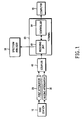
- FIG. 1 is a block diagram illustrating an apparatus for verifying diversity of a base station according to an embodiment of the present invention.
- the apparatus for verifying the diversity of the base station according to the present invention verifies a space-time coding used in the base station by utilizing an OFDM method.
- the apparatus includes a base station 10, a first attenuator 20, a second attenuator 30, a coupler 40, a spectrum analyzer 50, a terminal 60, and a computer 70.
- the base station 10 performs the same functions as those of a conventional base station using an OFDM method, which includes two antennas, uses a space-time coding, and transmits a radio signal through the two antennas.
- the base station 10 is connected to the first attenuator 20 and the second attenuator 30. Further, the base station 10 outputs a first antenna signal and a second antenna signal using the space-time coding according to the present invention.
- the base station 10 cannot output high power of more than 25 W, like a conventional base station, it is preferable that an output power level has a value of -70 dBm. Accordingly, it is preferable that the first antenna signal and the second antenna signal output from the base station 10 are output with power of -70 dBm.
- the first attenuator 20 attenuates the first antenna signal output from the base station 10 and the second attenuator 30 attenuates the second antenna signal output from the base station 10. That is, the first attenuator 20 attenuates the first antenna signal, which is output from the base station 10, according to the reception sensitivity of the terminal 60, and sends the attenuated signal to the coupler 40.
- the second attenuator 30 attenuates the second antenna signal, which is output from the base station 10, according to the reception sensitivity of the terminal 60, and sends the attenuated signal to the coupler 40.
- the coupler 40 couples the attenuated signals with each other and thus, outputs a single signal.
- the terminal 60 exchanges data and voice signal with a base station wirelessly in a mobile communication system, and includes a receiving unit 62 and a controller 64.
- the receiving unit 62 may be constructed by an RF circuit and receives the signal output from the coupler 40 in order to send the received signal to the spectrum analyzer 50 and the controller 64 under a predetermined control of the controller 64.
- the controller 64 performs an auto gain control (AGC) and an auto frequency control (AFC), and controls the receiving unit 62 according to the state of the base station 10.
- AGC auto gain control
- AFC auto frequency control
- the spectrum analyzer 50 is a general measuring unit that receives a modulated wave, analyzes a sideband, and displays the distribution of a frequency spectrum component.
- the spectrum analyzer 50 measures and displays a voltage controlled oscillator (VCO) frequency of the receiving unit 62 in the terminal 60.
- VCO voltage controlled oscillator
- the VCO frequency of the receiving unit 62 displayed on the spectrum analyzer 50 enables a user to check a synchronization state of the terminal 60.
- the computer 70 which is connected to the controller 64, monitors an operation state of the terminal 60 while receiving the signal from the base station 10, and performs a cyclic redundancy checking (CRC) in order to determine if an error exists in the signal received the receiving unit 62 through the controller 64.
- CRC cyclic redundancy checking
- a noise figure is determined according to the determined frequency band and modulation method.
- a reception sensitivity level of the terminal 60 is determined according to the noise figure.
- the degree of attenuation of the first attenuator 20 and the second attenuator 30 is determined according to the output level of the base station 10. Accordingly, the output level of the base station 10 and the degree of attenuation of the first attenuator 20 and the second attenuator 30 are adjusted, such that virtual radio channel environments can be constructed.
- FIG. 2 is a flowchart illustrating a method for verifying diversity performance of a base station according to an embodiment of the present invention
- FIG. 3 is a table illustrating a minimum input level reception sensitivity of a terminal provided in an IEEE 802.16a standard proposal
- FIG. 4 is a table illustrating a result of verification for diversity performance of a base station according to an embodiment of the present invention.
- a space-time coding verification process by the apparatus for verifying the diversity of the base station using an OFDM method according to the present invention will be described in detail with reference to FIGs. 1 to 4.
- the minimum input level reception sensitivity of the terminal 60 becomes -83 dBm as provided in the IEEE 802.16a standard proposal illustrated in FIG. 3.
- a noise figure can be determined using the frequency band and the minimum input level reception sensitivity of the terminal 60 in step 200. That is, when the frequency band is 10 MHz and the minimum input level reception sensitivity is -83 dBm, thermal noise and a noise figure can be calculated by Equations (1) and (2) below.
- the noise figure provided in the IEEE 802.16a standard proposal is 7 dB.
- the minimum input level reception sensitivity of the terminal 60 is determined to have a value of -87.6 dB, i.e., a value reduced by 4.6 dB.
- step 400 the first antenna signal and the second antenna signal output from the base station 10 are determined to have a value of -70 dBm. Because the base station 10 cannot output a high power of more than 25 W, like conventional base station, the output power level of the base station 10 is determined to be of about -70 dBm.
- the first attenuator 20 and the second attenuator 30 maintain their degree of attenuation at a value of -20 dB, because the first antenna signal and the second antenna signal are coupled with each other in the coupler 40, thereby increasing the power by 3 dB.
- the first attenuator 20, the second attenuator 30, and the coupler 40 have a loss similar to the loss (e.g., -17.6 dB) in virtual radio environments.
- the virtual radio environments are environments in which it is assumed that the minimum reception sensitivity of the terminal 60 has a value of -83 dB. Further, the power level of the base station 10 and the input level reception sensitivity of the terminal 60 may be changed by repeating the processes as described above.
- the first antenna signal is an antenna signal output from the base station 10.
- the second antenna signal is an antenna signal additionally output from the base station 10 together with the first antenna signal.
- the first attenuator 20 outputs the first antenna signal intact without attenuating the first antenna signal.
- the first attenuator 20 and the second attenuator 30 output the first antenna signal and the second antenna signal intact without attenuating both the first antenna signal and the second antenna signal.
- the terminal 60 in a case in which a space-time coding setting has been made, when receiving the first antenna signal and the second antenna signal, the terminal 60 can demodulate the received first antenna signal and second antenna signal. However, in a case in which a space-time coding setting has not been made, the terminal 60 can demodulate only the first antenna signal from among the received first antenna signal and second antenna signal.
- FIG. 4 is a table illustrating a verification result for diversity performance of a base station according to an embodiment of the present invention. More specifically, FIG. 4 illustrates an error state according to either an existence or absence of a space-time coding operation in the terminal 60, when both the first antenna signal and the second antenna signal are input to the terminal 60, or either the first antenna signal or the second antenna signal is input to the terminal 60, through the adjustment of attenuation by the first attenuator 20 and the second attenuator 30.
- a first attenuation represents the degree of attenuation of the first attenuator 20 and a second attenuation represents the degree of attenuation of the second attenuator 30.
- An existence or absence of a space-time coding setting in the terminal 60 represents whether or not a space-time coding demodulation function is set in the terminal 60.
- the terminal 60 can demodulate both the first antenna signal and second antenna signal.
- the terminal 60 can demodulate only the first antenna signal.
- the error state of FIG. 4 illustrates a result of a cyclic redundancy checking error check for representing whether or not a corresponding signal has been normally demodulated when the first antenna signal and second antenna signal have been input to the terminal 60.
- a first case in which the first attenuation has a value of -20 dB and the second attenuation has a value of - 20 dB represents a case in which the space-time coding has been applied to the base station 10. That is, this case represents a state in which both the first antenna signal and the second antenna signal are input to the terminal 60.
- a demodulation error -state when the cyclic redundancy checking error check has been performed must be in a "GOOD" state, that is, a state in which no error exists.
- a second case in which the first attenuation has a value of -20 dB and the second attenuation has a value of -40 dB represents a case in which the space-time coding has not been applied to the base station 10. That is, this case represents a state in which only the first antenna signal is input to the terminal 60.
- a demodulation error state when the cyclic redundancy checking error check has been performed must be in a "GOOD" state, that is, a state in which no error exists.
- a third case in which the first attenuation has a value of -40 dB and the second attenuation has a value of -20 dB represents a case in which the space-time coding has been applied to the base station 10. That is, this case represents a state in which only the second antenna signal is input to the terminal 60.
- a demodulation error state when the cyclic redundancy checking error check has been performed must be in a "GOOD" state, that is, a state in which no error exists.
- a fourth case in which the first attenuation has a value of -20 dB and the second attenuation has a value of -20 dB represents a case in which the space-time coding has been applied to the base station 10. That is, this case represents a state in which both the first antenna signal and the second antenna signal are input to the terminal 60.
- a demodulation error state when the cyclic redundancy checking error check has been performed must be in a "BAD" state, that is, a state in which an error has occurred.
- a fifth case in which the first attenuation has a value of -20 dB and the second attenuation has a value of -40 dB represents a case in which the space-time coding has not been applied to the base station 10. That is, this case represents a state in which the first antenna signal is input to the terminal 60. Even when the space-time coding has not been set in the terminal 60, because the terminal 60 can demodulate the input first antenna signal, a demodulation error state when the cyclic redundancy checking error check has been performed must be in a "GOOD" state, that is, a state in which no error exists.
- a sixth case in which the first attenuation has a value of -40 dB and the second attenuation has a value of -20 dB represents a case in which the space-time coding has been applied to the base station 10. That is, this case represents a state in which only the second antenna signal is input to the terminal 60.
- a demodulation error state when the cyclic redundancy checking error check has been performed must be in a "BAD" state, that is, a state in which an error has occurred.
- both the first antenna signal and the second antenna signal are input to the terminal 60, or either the first antenna signal or the second antenna signal is input to the terminal 60, when an error state is shown as described above, it is verified that a space-time coding of a corresponding base station is in a state in which there is no problem.
- a noise figure is determined according to the determined frequency band and modulation method
- the reception sensitivity level of a terminal is determined according to the noise figure.
- the degree of attenuation of a first attenuator and a second attenuator is determined according to the output level of the base station, such that conditions similar to actual radio environments can be formed. Therefore, a space-time coding method used in the base station can be verified.
- the present invention enables the space-time coding of the base station to be verified at a development step, such that development cost and time of the base station can be reduced. Therefore, cost reduction after the installation of the base station can be anticipated.
Applications Claiming Priority (2)
| Application Number | Priority Date | Filing Date | Title |
|---|---|---|---|
| KR1020030045641A KR100703278B1 (ko) | 2003-07-07 | 2003-07-07 | 이동통신 시스템에서 기지국의 stc 검증을 위한 장치 및 방법 |
| KR2003045641 | 2003-07-07 |
Publications (2)
| Publication Number | Publication Date |
|---|---|
| EP1496630A2 true EP1496630A2 (de) | 2005-01-12 |
| EP1496630A3 EP1496630A3 (de) | 2005-02-02 |
Family
ID=33448351
Family Applications (1)
| Application Number | Title | Priority Date | Filing Date |
|---|---|---|---|
| EP04016023A Withdrawn EP1496630A3 (de) | 2003-07-07 | 2004-07-07 | Gerät und Verfahren zur Diversity-Prüfung einer Basisstation in einem Mobilkommunikationssystem |
Country Status (3)
| Country | Link |
|---|---|
| US (1) | US7433684B2 (de) |
| EP (1) | EP1496630A3 (de) |
| KR (1) | KR100703278B1 (de) |
Families Citing this family (1)
| Publication number | Priority date | Publication date | Assignee | Title |
|---|---|---|---|---|
| EP3070274A1 (de) * | 2015-03-20 | 2016-09-21 | Sulzer Turbo Services Venlo B.V. | Turbinenschaufelanordnung mit gekühlten plattform |
Citations (5)
| Publication number | Priority date | Publication date | Assignee | Title |
|---|---|---|---|---|
| GB2272604A (en) * | 1992-11-10 | 1994-05-18 | Motorola Inc | Radio base station with diversity receiver testing. |
| EP0741465A2 (de) * | 1995-04-28 | 1996-11-06 | Nec Corporation | Mobiles Funkkommunikationssystem mit Senderdiversity |
| US6073026A (en) * | 1996-12-02 | 2000-06-06 | Hyundai Electronics Ind. Co., Ltd. | Method and device for testing link power control on mobile communications system |
| US6128474A (en) * | 1996-12-30 | 2000-10-03 | Lg Information & Communications, Ltd. | Test circuit of base station for mobile radio communication system |
| EP1237310A2 (de) * | 2001-02-26 | 2002-09-04 | Nec Corporation | Verfahren und Vorrichtung zum Testen einer Basisstation in einem CDMA Kommunikationssystem |
Family Cites Families (11)
| Publication number | Priority date | Publication date | Assignee | Title |
|---|---|---|---|---|
| JP3859738B2 (ja) * | 1993-05-26 | 2006-12-20 | 大日本住友製薬株式会社 | キナゾリノン誘導体 |
| JP2000023230A (ja) | 1998-06-26 | 2000-01-21 | Mitsubishi Electric Corp | 遠隔保守システム及び遠隔保守方法 |
| EP1152548A1 (de) * | 2000-05-05 | 2001-11-07 | Lucent Technologies Inc. | Erhöhte Datenübertragungskapazität für Schnurloses Netzwerk mit hoher Datenrate |
| JP2001339338A (ja) * | 2000-05-30 | 2001-12-07 | Nec Corp | 保守監視システムおよび保守監視方法 |
| KR100465996B1 (ko) * | 2000-09-27 | 2005-01-13 | 샬롬엔지니어링 주식회사 | 무선신호중계장치 모니터링 시스템의 제어방법 |
| KR20020039426A (ko) * | 2000-11-21 | 2002-05-27 | 오길록 | Cdma 이동통신시스템에서의 무선프로토콜 검증을 위한시뮬레이터 |
| JP2004089311A (ja) * | 2002-08-30 | 2004-03-25 | Fuji Photo Film Co Ltd | 超音波送受信装置 |
| JP3679075B2 (ja) * | 2002-09-13 | 2005-08-03 | 松下電器産業株式会社 | 無線送信装置および無線送信方法 |
| US7394860B2 (en) * | 2002-10-02 | 2008-07-01 | Nortel Networks Limited | Combined space-time decoding |
| US6894657B2 (en) * | 2003-05-19 | 2005-05-17 | Fidelity Comtech, Inc. | Bi-directional vector modulator |
| US7443818B2 (en) * | 2003-12-15 | 2008-10-28 | Intel Corporation | Method, apparatus and system of multiple-input-multiple-output wireless communication |
-
2003
- 2003-07-07 KR KR1020030045641A patent/KR100703278B1/ko not_active IP Right Cessation
-
2004
- 2004-07-07 US US10/885,986 patent/US7433684B2/en not_active Expired - Fee Related
- 2004-07-07 EP EP04016023A patent/EP1496630A3/de not_active Withdrawn
Patent Citations (5)
| Publication number | Priority date | Publication date | Assignee | Title |
|---|---|---|---|---|
| GB2272604A (en) * | 1992-11-10 | 1994-05-18 | Motorola Inc | Radio base station with diversity receiver testing. |
| EP0741465A2 (de) * | 1995-04-28 | 1996-11-06 | Nec Corporation | Mobiles Funkkommunikationssystem mit Senderdiversity |
| US6073026A (en) * | 1996-12-02 | 2000-06-06 | Hyundai Electronics Ind. Co., Ltd. | Method and device for testing link power control on mobile communications system |
| US6128474A (en) * | 1996-12-30 | 2000-10-03 | Lg Information & Communications, Ltd. | Test circuit of base station for mobile radio communication system |
| EP1237310A2 (de) * | 2001-02-26 | 2002-09-04 | Nec Corporation | Verfahren und Vorrichtung zum Testen einer Basisstation in einem CDMA Kommunikationssystem |
Also Published As
| Publication number | Publication date |
|---|---|
| US7433684B2 (en) | 2008-10-07 |
| KR100703278B1 (ko) | 2007-04-03 |
| EP1496630A3 (de) | 2005-02-02 |
| US20050009513A1 (en) | 2005-01-13 |
| KR20050005817A (ko) | 2005-01-15 |
Similar Documents
| Publication | Publication Date | Title |
|---|---|---|
| EP0610030B1 (de) | Verfahren und Einrichtung zur Sendeleistungssteuerung eines zellularen Funksystems | |
| US6700875B1 (en) | System, device, and method for selecting a channel in a multichannel communication network | |
| Fifer et al. | The low-cost packet radio | |
| US6603810B1 (en) | Combined system for calibrating receiver gain and measuring antenna impedance match and method of operation | |
| US7787574B2 (en) | Reception terminal apparatus | |
| EP1298876A1 (de) | OFDM- Sender und Empfänger | |
| US8433009B2 (en) | Method for determining as to whether a received signal includes a data signal | |
| KR102243877B1 (ko) | 헤드엔드 장치 및 이를 이용한 동기 검출 오류를 복구하는 방법 | |
| Komaki et al. | Characteristics of a high capacity 16 QAM digital radio system in multipath fading | |
| US10091742B2 (en) | Wireless communication device | |
| EP1496630A2 (de) | Gerät und Verfahren zur Diversity-Prüfung einer Basisstation in einem Mobilkommunikationssystem | |
| US7027776B2 (en) | Transverter control mechanism for a wireless modem in a broadband access system | |
| JP2002094408A (ja) | 受信装置 | |
| JP2800567B2 (ja) | マルチパス通信用無線装置 | |
| US6259900B1 (en) | Radio frequency signal folding-back transmitting/receiving circuit and radio transmitting/receiving apparatus for use therewith | |
| JP3815313B2 (ja) | 無線通信装置およびこれを用いた折り返し試験方法 | |
| JP3522225B2 (ja) | 無線装置およびその受信故障検出方法 | |
| JP2004128719A (ja) | 室内再送信システム及び室内再送信装置 | |
| JP2002198834A (ja) | 干渉軽減機能を備える無線通信システム | |
| JP2912253B2 (ja) | アンテナ故障検出回路 | |
| US7313205B2 (en) | Method and apparatus for frequency correction in wireless local area network systems | |
| US6341226B1 (en) | Mobile communication apparatus and method of receiving mobile communication signals | |
| EP1303068A1 (de) | Radioendstellengerät und demodulationsverfahren | |
| JP2590736B2 (ja) | 送信出力制御方法 | |
| Master | Practical Tips on WiMAX Field Measurements |
Legal Events
| Date | Code | Title | Description |
|---|---|---|---|
| PUAI | Public reference made under article 153(3) epc to a published international application that has entered the european phase |
Free format text: ORIGINAL CODE: 0009012 |
|
| PUAL | Search report despatched |
Free format text: ORIGINAL CODE: 0009013 |
|
| 17P | Request for examination filed |
Effective date: 20040707 |
|
| AK | Designated contracting states |
Kind code of ref document: A2 Designated state(s): AT BE BG CH CY CZ DE DK EE ES FI FR GB GR HU IE IT LI LU MC NL PL PT RO SE SI SK TR |
|
| AX | Request for extension of the european patent |
Extension state: AL HR LT LV MK |
|
| AK | Designated contracting states |
Kind code of ref document: A3 Designated state(s): AT BE BG CH CY CZ DE DK EE ES FI FR GB GR HU IE IT LI LU MC NL PL PT RO SE SI SK TR |
|
| AX | Request for extension of the european patent |
Extension state: AL HR LT LV MK |
|
| 17Q | First examination report despatched |
Effective date: 20050623 |
|
| AKX | Designation fees paid |
Designated state(s): DE FR GB |
|
| RAP1 | Party data changed (applicant data changed or rights of an application transferred) |
Owner name: SAMSUNG ELECTRONICS CO., LTD. |
|
| STAA | Information on the status of an ep patent application or granted ep patent |
Free format text: STATUS: THE APPLICATION IS DEEMED TO BE WITHDRAWN |
|
| 18D | Application deemed to be withdrawn |
Effective date: 20131120 |