EP1496577B1 - Boîtier de terminaison et de jonction électrique - Google Patents
Boîtier de terminaison et de jonction électrique Download PDFInfo
- Publication number
- EP1496577B1 EP1496577B1 EP04012404A EP04012404A EP1496577B1 EP 1496577 B1 EP1496577 B1 EP 1496577B1 EP 04012404 A EP04012404 A EP 04012404A EP 04012404 A EP04012404 A EP 04012404A EP 1496577 B1 EP1496577 B1 EP 1496577B1
- Authority
- EP
- European Patent Office
- Prior art keywords
- electrical
- module
- housing
- plug
- connection
- Prior art date
- Legal status (The legal status is an assumption and is not a legal conclusion. Google has not performed a legal analysis and makes no representation as to the accuracy of the status listed.)
- Expired - Lifetime
Links
- 238000005266 casting Methods 0.000 claims description 3
- 238000005259 measurement Methods 0.000 claims 3
- 230000002950 deficient Effects 0.000 description 4
- 238000010438 heat treatment Methods 0.000 description 4
- 230000015556 catabolic process Effects 0.000 description 2
- 239000003795 chemical substances by application Substances 0.000 description 2
- 239000008393 encapsulating agent Substances 0.000 description 2
- 239000012080 ambient air Substances 0.000 description 1
- 230000000903 blocking effect Effects 0.000 description 1
- 230000001419 dependent effect Effects 0.000 description 1
- 230000000694 effects Effects 0.000 description 1
- 238000005538 encapsulation Methods 0.000 description 1
- 230000001747 exhibiting effect Effects 0.000 description 1
- 230000001771 impaired effect Effects 0.000 description 1
- 238000000034 method Methods 0.000 description 1
- 238000012544 monitoring process Methods 0.000 description 1
- 230000000704 physical effect Effects 0.000 description 1
- 230000005855 radiation Effects 0.000 description 1
- 229920003002 synthetic resin Polymers 0.000 description 1
- 239000000057 synthetic resin Substances 0.000 description 1
- 238000012795 verification Methods 0.000 description 1
- 238000010792 warming Methods 0.000 description 1
Images

Classifications
-
- H—ELECTRICITY
- H01—ELECTRIC ELEMENTS
- H01R—ELECTRICALLY-CONDUCTIVE CONNECTIONS; STRUCTURAL ASSOCIATIONS OF A PLURALITY OF MUTUALLY-INSULATED ELECTRICAL CONNECTING ELEMENTS; COUPLING DEVICES; CURRENT COLLECTORS
- H01R13/00—Details of coupling devices of the kinds covered by groups H01R12/70 or H01R24/00 - H01R33/00
- H01R13/66—Structural association with built-in electrical component
- H01R13/6608—Structural association with built-in electrical component with built-in single component
- H01R13/6641—Structural association with built-in electrical component with built-in single component with diode
-
- H—ELECTRICITY
- H02—GENERATION; CONVERSION OR DISTRIBUTION OF ELECTRIC POWER
- H02S—GENERATION OF ELECTRIC POWER BY CONVERSION OF INFRARED RADIATION, VISIBLE LIGHT OR ULTRAVIOLET LIGHT, e.g. USING PHOTOVOLTAIC [PV] MODULES
- H02S40/00—Components or accessories in combination with PV modules, not provided for in groups H02S10/00 - H02S30/00
- H02S40/30—Electrical components
- H02S40/34—Electrical components comprising specially adapted electrical connection means to be structurally associated with the PV module, e.g. junction boxes
-
- Y—GENERAL TAGGING OF NEW TECHNOLOGICAL DEVELOPMENTS; GENERAL TAGGING OF CROSS-SECTIONAL TECHNOLOGIES SPANNING OVER SEVERAL SECTIONS OF THE IPC; TECHNICAL SUBJECTS COVERED BY FORMER USPC CROSS-REFERENCE ART COLLECTIONS [XRACs] AND DIGESTS
- Y02—TECHNOLOGIES OR APPLICATIONS FOR MITIGATION OR ADAPTATION AGAINST CLIMATE CHANGE
- Y02E—REDUCTION OF GREENHOUSE GAS [GHG] EMISSIONS, RELATED TO ENERGY GENERATION, TRANSMISSION OR DISTRIBUTION
- Y02E10/00—Energy generation through renewable energy sources
- Y02E10/50—Photovoltaic [PV] energy
Definitions
- the invention relates to an electrical connection and connection box for connecting solar cells of a solar cell module, with a housing, for connecting and connecting introduced into the housing lines with each other or provided in the housing electrical and / or electronic devices.
- a voltage is applied to the shaded solar cell, which voltage is dependent on the position of the shaded solar cell in the series connection. If this voltage applied to the shaded solar cell is greater than its blocking voltage, a breakdown and thus permanent damage will occur in the solar cell.
- bypass diodes are often used, which are connected in anti-parallel to the solar cells. In this way, it is achieved that a shaded solar cell does not contribute more to the total voltage of the solar cell module, but the current flow is still maintained. The solar cell module thus only shows a reduced operating voltage, but does not completely fail. In addition, no power is converted in the shaded solar cell, so that damage to the shaded solar cell can be avoided.
- each solar cell of a solar cell module could be associated with exactly one diode. However, it is often the case that a plurality each solar cell connected in series is protected by a common diode.
- the object of the invention to provide an intended for the connection of solar cell modules electrical connection and junction box, which ensures easy replacement therein provided electrical and / or electronic devices, such as defective bypass diodes, and moreover preferably shows only slight warming during operation.
- an electrical and / or electronic devices exhibiting Ansteckmodul is provided, which is infected by means of a plug and a socket comprehensive connector to the housing in that the electrical and / or electronic devices of the clip-on module are connected to the lines or electrical and / or electronic devices provided in the housing, wherein the electrical and / or electrical devices of the clip-on module comprise a bypass diode for the solar cells .
- a different from the housing of the electrical connection and junction box plug-in module is provided, which may have electrical devices, such as diodes.
- electrical devices such as diodes.
- This is advantageous in that as to replace the electrical and / or electronic devices of the plug-in module, ie, for. B. of bypass diodes for solar cells of a solar cell module, the housing of the electrical connection and junction box no longer needs to be opened. Rather, the Ansteckmodul that a defective electrical and / or electronic device, ie z. B. has a defective bypass diode, simply pulled off and replaced with a new plug-in module that can be easily re-attached to the housing.
- the heat generated by the separate provision of the lapel module by the provided in the plug-in module electrical and / or electronic devices heat only very minor parts on the housing of the electrical connection and junction box passes. In comparison with the prior art thus heating of the electrical connection and junction box can be significantly reduced.
- the plug-in module can be connected directly to the housing by means of the plug connection, wherein as a plug connection z.
- a plug connection z. B. a provided on the housing of the electrical connection and junction box connector and cooperating with this connector socket can be provided on the plug-in module.
- an adapter is provided between the housing and the Ansteckmodul.
- such an intermediate plug can have a diagnostic connection for an external measuring device. This creates the opportunity to check connected or connected via the electrical connection and connection box devices during operation.
- the insectstekker has a Meß effetsanschluß for connecting a measuring line.
- a measuring or display device can also be located away from the electrical connection and junction box, so that must not be measured directly to the electrical connection and junction box for checking connected by means of the electrical connection and junction box or connected electrical equipment.
- an adapter has a higher flexibility, in particular, the adapter can namely without further notice of the electrical connection and junction box be removed so that it does not interfere in normal operation there.
- the electrical and / or electronic devices in the plug-in module freely, z. B. on a board, be arranged. According to a preferred embodiment of the invention, however, it is provided that the electrical and / or electronic devices are cast in the Ansteckmodul in a Vergussstoff. In particular, casting into a synthetic resin agent is considered, as well as from other areas in electrical circuits known.
- the encapsulant By applied directly to the electrical and / or electronic devices encapsulant resulting in the electrical and / or electronic devices heat can be dissipated better of these, as if the electrical and / or electronic devices only with the present in the Ansteckmodul ambient air in touch stood.
- the encapsulant protects the electrical and / or electronic devices from external influences, in particular namely mechanical loads or the effect of moisture and moisture.
- the electrical connection and connection box is provided for the connection of solar cells of a solar cell module.
- the electrical connection and junction box is attached by means of the housing to the solar cell module or a roof.
- the plug-in module is tool-free detachable from the housing.
- the clip-on module preferably has a plurality of bypass diodes for the solar cells of the solar cell module. This allows a simple change of the plug-in module to replace defective bypass diodes, without having to open the housing of the electrical connection and junction box and without using a tool.
- bypass diodes in the plug-in module are cast into a casting agent, so the power converted into the bypass diodes, which leads to a heating of the bypass diodes, well discharged to the outside.
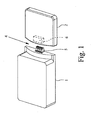
- FIG. 1 is an electrical connection and junction box according to a preferred embodiment of the invention in a perspective view can be seen, which has a housing 1 and a pin 2.
- a so-called solar can so to a box for connecting and connecting multiple solar cells of a solar cell module, including with bypass diodes.
- the housing 1 lines not shown can be fed, for. B. through a side wall or through the bottom of the housing 1 therethrough.
- connection options typically in the form of not shown terminals, provided.
- An interconnection which can be achieved with the connection possibilities which are typically present in the form of terminals is shown by way of example in FIG. 2.
- the plug-in module 2 has, as also shown in FIG. 2, diodes 3, which serve as bypass diodes for solar cells of a solar cell module.
- connection module 3 can be attached to the housing 1 by means of a plug connection 4.
- the connector 4 consists of a provided on the housing 1 connector 5 and a connector 5 corresponding socket 6 on the connection module 2. About this connector 4 those line connections from the housing 1 are guided in the connection module 2, which must be connected to the diodes 3 as can be seen in detail from FIG. 2.
- the connector 4 with connector 5 and 6 socket is designed such that the connection module 2 is simply plugged onto the housing 1, without having to use a tool.
- plug 5 and socket 6 of the connector 4 can be readily formed so that the achieved connection between the housing 1 and the connection module 2 is so stable that no further means for fixing and holding the connection module 2 are provided on the housing 1 have to.
- a non-illustrated adapter plug can be provided between the housing 1 and the connection module 2.
- Such an intermediary is typically designed such that it is provided on the side of the housing 1 with a socket which corresponds to the socket 6 of the connection module 2, and on its side facing the connection module 2 side is provided with a plug which the plug 5 of the housing. 1 equivalent.
- the adapter plug simultaneously or alternatively has a diagnostic connection for an external measuring device and a measuring line connection for connecting a measuring line. This makes it easy to carry out various verification procedures, namely, namely, it is possible to check whether the diodes 3 are still fully functional and whether the individual solar cells or rows of solar cells operate in accordance with regulations.
- the diodes 3 are embedded in the connection module 2 in a Vergusskar, in such a way that this Vergussstoff is applied directly to the diodes 3 and also has complete contact with the inner walls of the connection module 2. With the help of this Vergussffens it is achieved that the heat generated in the diodes 3 can be effectively dissipated to the outside of the environment of the connection module 2.
Landscapes
- Photovoltaic Devices (AREA)
- Details Of Connecting Devices For Male And Female Coupling (AREA)
- Coupling Device And Connection With Printed Circuit (AREA)
Claims (5)
- Prise de raccordement et de liaison électrique pour raccorder un module de cellule solaire, comportant un boîtier (1), pour le raccordement et la liaison de lignes insérées dans le boîtier (1) les unes aux autres, respectivement avec des dispositifs électriques et/ou électroniques prévus dans le boîtier, caractérisée en ce que un module enfichable (2) présentant des dispositifs électriques et/ou électroniques est prévu, lequel est enfiché sur le boîtier (1) au moyen d'une liaison à connecteur comprenant un connecteur mâle (5) et un connecteur femelle (6), de telle sorte que les dispositifs électriques et/ou électroniques du module enfichable (2) soient reliés aux lignes, respectivement aux dispositifs électriques et/ou électroniques prévus dans le boîtier (1), moyennant quoi les dispositifs électriques et/ou électroniques du module enfichable (2) comprennent une diode de dérivation (3) destinée aux cellules solaires.
- Prise de raccordement et de liaison électrique selon la revendication 1, caractérisée en ce que, entre le boîtier (1) et le module enfichable (2), un adaptateur est prévu.
- Prise de raccordement et de liaison électrique selon la revendication 2, caractérisée en ce que l'adaptateur présente un raccordement de diagnostic d'un appareil de mesure externe et/ou un raccordement de ligne de mesure pour raccorder une ligne de mesure.
- Prise de raccordement et de liaison électrique selon une des revendications 1 à 3, caractérisée en ce que les dispositifs électriques et/ou électroniques sont coulés dans le module enfichable en une masse de scellement.
- Prise de raccordement et de liaison électrique selon une des revendications 1 à 4, caractérisée en ce que le module enfichable (2) présente une pluralité de diodes de dérivation (3).
Applications Claiming Priority (2)
| Application Number | Priority Date | Filing Date | Title |
|---|---|---|---|
| DE10331780A DE10331780B4 (de) | 2003-07-11 | 2003-07-11 | Elektrische Anschluß- und Verbindungsdose |
| DE10331780 | 2003-07-11 |
Publications (3)
| Publication Number | Publication Date |
|---|---|
| EP1496577A2 EP1496577A2 (fr) | 2005-01-12 |
| EP1496577A3 EP1496577A3 (fr) | 2005-10-05 |
| EP1496577B1 true EP1496577B1 (fr) | 2007-07-25 |
Family
ID=33441750
Family Applications (1)
| Application Number | Title | Priority Date | Filing Date |
|---|---|---|---|
| EP04012404A Expired - Lifetime EP1496577B1 (fr) | 2003-07-11 | 2004-05-26 | Boîtier de terminaison et de jonction électrique |
Country Status (4)
| Country | Link |
|---|---|
| EP (1) | EP1496577B1 (fr) |
| AT (1) | ATE368314T1 (fr) |
| DE (2) | DE10331780B4 (fr) |
| ES (1) | ES2290588T3 (fr) |
Cited By (4)
| Publication number | Priority date | Publication date | Assignee | Title |
|---|---|---|---|---|
| CN102195695B (zh) * | 2010-03-02 | 2013-11-20 | 电信科学技术研究院 | 天线校准的方法及装置 |
| EP2672527A1 (fr) | 2012-06-07 | 2013-12-11 | Hanwha Q-CELLS GmbH | Module solaire doté d'un dispositif d'enfichage |
| CN101779339B (zh) * | 2007-08-10 | 2015-11-25 | 泰科电子Amp有限责任公司 | 用于光电太阳能装置的电连接系统 |
| DE102015218526A1 (de) | 2015-09-25 | 2017-03-30 | Hanwha Q Cells Gmbh | Anschlussanordnung für ein Solarmodul |
Families Citing this family (13)
| Publication number | Priority date | Publication date | Assignee | Title |
|---|---|---|---|---|
| DE102004053942A1 (de) * | 2004-11-09 | 2006-05-11 | Solarwatt Solar-Systeme Gmbh | Anschlusseinheit für photovoltaische Solarmodule |
| DE102005012213B4 (de) * | 2005-01-26 | 2009-01-15 | G. Spelsberg Gmbh & Co. Kg | Anschlußschaltung |
| DE102005036153B4 (de) | 2005-05-24 | 2007-03-22 | Fraunhofer-Gesellschaft zur Förderung der angewandten Forschung e.V. | Schutzschalteinrichtung für ein Solarmodul |
| DE102008057327B3 (de) * | 2008-11-14 | 2010-06-24 | Yamaichi Electronics Deutschland Gmbh | Solarpaneel, Verfahren zum Herstellen und Überbrückungsdose |
| DE102009004100A1 (de) * | 2009-01-08 | 2010-07-15 | Yamaichi Electronics Deutschland Gmbh | Solarpaneel und Verfahren |
| DE102009018360A1 (de) | 2009-04-23 | 2010-11-04 | Rena Gmbh | Verfahren und Vorrichtung zur elektrolytischen Behandlung von Solarzellen |
| ITMI20110917A1 (it) * | 2011-05-23 | 2012-11-24 | Compel Electronics S P A | Scatola di giunzione per pannelli fotovoltaici |
| WO2016069554A1 (fr) * | 2014-10-28 | 2016-05-06 | Sunedison, Inc. | Modules photovoltaïques comprenant des diodes de dérivation externes |
| US10404208B2 (en) | 2015-06-02 | 2019-09-03 | Ja Solar Usa Inc. | Apparatus and method of a universal module junction box |
| EP3304729A4 (fr) * | 2015-06-02 | 2019-01-09 | Ja Solar USA | Appareil et procédé pour un boîtier de connexion de module universel |
| CN107174753B (zh) | 2017-05-15 | 2019-09-03 | 中国医学科学院肿瘤医院 | 多机械臂式术中放射治疗装置 |
| CN109728487A (zh) * | 2017-10-30 | 2019-05-07 | 泰科电子(上海)有限公司 | 适配器 |
| DE102021125242A1 (de) | 2021-09-29 | 2023-03-30 | Weidmüller Interface GmbH & Co. KG | Photovoltaikmodul und Anschlussanordnung für ein Photovoltaikmodul |
Family Cites Families (9)
| Publication number | Priority date | Publication date | Assignee | Title |
|---|---|---|---|---|
| DE3319141A1 (de) * | 1982-06-08 | 1983-12-08 | The Singer Co., 06904 Stamford, Conn. | Leiterplatten-steckmodul |
| GB2183936A (en) * | 1985-12-06 | 1987-06-10 | Plessey Co Plc | Power supply adaptor |
| DE4027478A1 (de) * | 1990-08-30 | 1992-03-05 | Robert Dipl Ing Michaelides | Schaltungsaufbau und herstellungsverfahren |
| CH681338A5 (en) * | 1990-09-11 | 1993-02-26 | Comat Ag | Plug socket for relay or electronic circuit module - has termination section with internal contacts and plug-in element fitted to ends of lead wires |
| DE19507644A1 (de) * | 1995-03-04 | 1996-09-05 | Sitron Sparkuhle Gmbh | Lichtschrankeneinrichtung |
| DE19917597A1 (de) * | 1999-04-19 | 2000-10-26 | Siemens Ag | Installationssystem für Elektrokomponenten einer Niederspannungsverteileranlage |
| JP2003008042A (ja) * | 2001-06-18 | 2003-01-10 | Sumitomo Wiring Syst Ltd | 太陽電池モジュール接続方法 |
| DE20111776U1 (de) * | 2001-07-17 | 2002-11-28 | Luxmate Controls Gmbh Dornbirn | Anschlußeinrichtung für die Hausleittechnik |
| JP2004014920A (ja) * | 2002-06-10 | 2004-01-15 | Sumitomo Wiring Syst Ltd | ケーブル連結部構造 |
-
2003
- 2003-07-11 DE DE10331780A patent/DE10331780B4/de not_active Expired - Fee Related
-
2004
- 2004-05-26 DE DE502004004419T patent/DE502004004419D1/de not_active Expired - Lifetime
- 2004-05-26 EP EP04012404A patent/EP1496577B1/fr not_active Expired - Lifetime
- 2004-05-26 AT AT04012404T patent/ATE368314T1/de not_active IP Right Cessation
- 2004-05-26 ES ES04012404T patent/ES2290588T3/es not_active Expired - Lifetime
Cited By (5)
| Publication number | Priority date | Publication date | Assignee | Title |
|---|---|---|---|---|
| CN101779339B (zh) * | 2007-08-10 | 2015-11-25 | 泰科电子Amp有限责任公司 | 用于光电太阳能装置的电连接系统 |
| CN102195695B (zh) * | 2010-03-02 | 2013-11-20 | 电信科学技术研究院 | 天线校准的方法及装置 |
| EP2672527A1 (fr) | 2012-06-07 | 2013-12-11 | Hanwha Q-CELLS GmbH | Module solaire doté d'un dispositif d'enfichage |
| DE102015218526A1 (de) | 2015-09-25 | 2017-03-30 | Hanwha Q Cells Gmbh | Anschlussanordnung für ein Solarmodul |
| DE102015218526B4 (de) | 2015-09-25 | 2023-05-25 | Hanwha Q Cells Gmbh | Anschlussanordnung für ein Solarmodul |
Also Published As
| Publication number | Publication date |
|---|---|
| ES2290588T3 (es) | 2008-02-16 |
| ATE368314T1 (de) | 2007-08-15 |
| EP1496577A2 (fr) | 2005-01-12 |
| DE10331780B4 (de) | 2005-06-09 |
| DE10331780A1 (de) | 2005-03-03 |
| DE502004004419D1 (de) | 2007-09-06 |
| EP1496577A3 (fr) | 2005-10-05 |
Similar Documents
| Publication | Publication Date | Title |
|---|---|---|
| EP1496577B1 (fr) | Boîtier de terminaison et de jonction électrique | |
| DE10358140B4 (de) | Elektrische Anschluß- und Verbindungsdose für ein Solarzellenmodul | |
| DE102005025976B4 (de) | Elektrische Anschluß- und Verbindungsdose für ein Solarzellenmodul | |
| DE102005012213B4 (de) | Anschlußschaltung | |
| DE102009034239A1 (de) | Halbleitervorrichtung mit Stiftanschlüssen | |
| DE102007020843A1 (de) | Paneldose | |
| WO2006079503A2 (fr) | Circuit de protection à dérivation de courant destiné à un module de cellules solaires | |
| DE102013100607A1 (de) | Wechselrichter mit zweiteiligem Gehäuse | |
| DE102007005436B4 (de) | Trägermodul für einen Wechselrichter | |
| DE102005044939B4 (de) | Elektrische Anschlußdose | |
| DE102018101606A1 (de) | Strommessmodul für Photovoltaik-Verbinderband | |
| DE102011052928A1 (de) | Anordnung mit einem Solarzellenmodul, einer Anschlussdose, einem Anschlussstecker und einer Anschlussleitung | |
| EP1672702B1 (fr) | Boîte de jonction pour un module de cellule solaire | |
| EP2056357A2 (fr) | Agencement doté d'un module de cellule solaire et d'un cadre | |
| WO2022089947A1 (fr) | Module de cellules solaires | |
| EP2745331B1 (fr) | Boîtier répartiteur de mesure destiné à déterminer le courant de branche dans des installations photovoltaïques | |
| DE102014202350A1 (de) | Integrierte galvanisch getrennte Messvorrichtungen und Verfahren zumHerstellen von integrierten galvanisch getrennten Messvorrichtungen | |
| EP0263391B1 (fr) | Dispositif pour recevoir, préparer, exploiter et transmettre des signaux électriques | |
| DE10021907B4 (de) | Brennstoffzellensystem mit einem Brennstoffzellenstapel mit integrierter Verpolschutzdiode | |
| DE202004020974U1 (de) | Elektrische Anschluß- und Verbindungsdose | |
| DE19704801C2 (de) | Netzbetriebener Elektromotor | |
| EP2267462A1 (fr) | Composant d'adaptateur | |
| EP2482326A2 (fr) | Elément à semi-conducteur de puissance et agencement d'un élément à semi-conducteur de puissance sur au moins une cellule solaire | |
| WO2012065747A1 (fr) | Dispositif à composants semi-conducteurs pour installations pv | |
| DE202010000710U1 (de) | Solarpaneel |
Legal Events
| Date | Code | Title | Description |
|---|---|---|---|
| PUAI | Public reference made under article 153(3) epc to a published international application that has entered the european phase |
Free format text: ORIGINAL CODE: 0009012 |
|
| AK | Designated contracting states |
Kind code of ref document: A2 Designated state(s): AT BE BG CH CY CZ DE DK EE ES FI FR GB GR HU IE IT LI LU MC NL PL PT RO SE SI SK TR |
|
| AX | Request for extension of the european patent |
Extension state: AL HR LT LV MK |
|
| PUAL | Search report despatched |
Free format text: ORIGINAL CODE: 0009013 |
|
| AK | Designated contracting states |
Kind code of ref document: A3 Designated state(s): AT BE BG CH CY CZ DE DK EE ES FI FR GB GR HU IE IT LI LU MC NL PL PT RO SE SI SK TR |
|
| AX | Request for extension of the european patent |
Extension state: AL HR LT LV MK |
|
| 17P | Request for examination filed |
Effective date: 20060206 |
|
| AKX | Designation fees paid |
Designated state(s): AT BE BG CH CY CZ DE DK EE ES FI FR GB GR HU IE IT LI LU MC NL PL PT RO SE SI SK TR |
|
| GRAP | Despatch of communication of intention to grant a patent |
Free format text: ORIGINAL CODE: EPIDOSNIGR1 |
|
| GRAS | Grant fee paid |
Free format text: ORIGINAL CODE: EPIDOSNIGR3 |
|
| GRAA | (expected) grant |
Free format text: ORIGINAL CODE: 0009210 |
|
| AK | Designated contracting states |
Kind code of ref document: B1 Designated state(s): AT BE BG CH CY CZ DE DK EE ES FI FR GB GR HU IE IT LI LU MC NL PL PT RO SE SI SK TR |
|
| REG | Reference to a national code |
Ref country code: GB Ref legal event code: FG4D Free format text: NOT ENGLISH |
|
| REG | Reference to a national code |
Ref country code: CH Ref legal event code: EP |
|
| REG | Reference to a national code |
Ref country code: IE Ref legal event code: FG4D Free format text: LANGUAGE OF EP DOCUMENT: GERMAN |
|
| REF | Corresponds to: |
Ref document number: 502004004419 Country of ref document: DE Date of ref document: 20070906 Kind code of ref document: P |
|
| REG | Reference to a national code |
Ref country code: SE Ref legal event code: TRGR |
|
| PG25 | Lapsed in a contracting state [announced via postgrant information from national office to epo] |
Ref country code: FI Free format text: LAPSE BECAUSE OF FAILURE TO SUBMIT A TRANSLATION OF THE DESCRIPTION OR TO PAY THE FEE WITHIN THE PRESCRIBED TIME-LIMIT Effective date: 20070725 Ref country code: BG Free format text: LAPSE BECAUSE OF FAILURE TO SUBMIT A TRANSLATION OF THE DESCRIPTION OR TO PAY THE FEE WITHIN THE PRESCRIBED TIME-LIMIT Effective date: 20071025 Ref country code: PT Free format text: LAPSE BECAUSE OF FAILURE TO SUBMIT A TRANSLATION OF THE DESCRIPTION OR TO PAY THE FEE WITHIN THE PRESCRIBED TIME-LIMIT Effective date: 20071226 Ref country code: NL Free format text: LAPSE BECAUSE OF FAILURE TO SUBMIT A TRANSLATION OF THE DESCRIPTION OR TO PAY THE FEE WITHIN THE PRESCRIBED TIME-LIMIT Effective date: 20070725 |
|
| NLV1 | Nl: lapsed or annulled due to failure to fulfill the requirements of art. 29p and 29m of the patents act | ||
| REG | Reference to a national code |
Ref country code: ES Ref legal event code: FG2A Ref document number: 2290588 Country of ref document: ES Kind code of ref document: T3 |
|
| GBV | Gb: ep patent (uk) treated as always having been void in accordance with gb section 77(7)/1977 [no translation filed] |
Effective date: 20070725 |
|
| PG25 | Lapsed in a contracting state [announced via postgrant information from national office to epo] |
Ref country code: PL Free format text: LAPSE BECAUSE OF FAILURE TO SUBMIT A TRANSLATION OF THE DESCRIPTION OR TO PAY THE FEE WITHIN THE PRESCRIBED TIME-LIMIT Effective date: 20070725 |
|
| REG | Reference to a national code |
Ref country code: IE Ref legal event code: FD4D |
|
| EN | Fr: translation not filed | ||
| PG25 | Lapsed in a contracting state [announced via postgrant information from national office to epo] |
Ref country code: GR Free format text: LAPSE BECAUSE OF FAILURE TO SUBMIT A TRANSLATION OF THE DESCRIPTION OR TO PAY THE FEE WITHIN THE PRESCRIBED TIME-LIMIT Effective date: 20071026 Ref country code: DK Free format text: LAPSE BECAUSE OF FAILURE TO SUBMIT A TRANSLATION OF THE DESCRIPTION OR TO PAY THE FEE WITHIN THE PRESCRIBED TIME-LIMIT Effective date: 20070725 |
|
| PG25 | Lapsed in a contracting state [announced via postgrant information from national office to epo] |
Ref country code: GB Free format text: LAPSE BECAUSE OF FAILURE TO SUBMIT A TRANSLATION OF THE DESCRIPTION OR TO PAY THE FEE WITHIN THE PRESCRIBED TIME-LIMIT Effective date: 20070725 Ref country code: IE Free format text: LAPSE BECAUSE OF FAILURE TO SUBMIT A TRANSLATION OF THE DESCRIPTION OR TO PAY THE FEE WITHIN THE PRESCRIBED TIME-LIMIT Effective date: 20070725 Ref country code: SK Free format text: LAPSE BECAUSE OF FAILURE TO SUBMIT A TRANSLATION OF THE DESCRIPTION OR TO PAY THE FEE WITHIN THE PRESCRIBED TIME-LIMIT Effective date: 20070725 |
|
| PLBE | No opposition filed within time limit |
Free format text: ORIGINAL CODE: 0009261 |
|
| STAA | Information on the status of an ep patent application or granted ep patent |
Free format text: STATUS: NO OPPOSITION FILED WITHIN TIME LIMIT |
|
| PG25 | Lapsed in a contracting state [announced via postgrant information from national office to epo] |
Ref country code: RO Free format text: LAPSE BECAUSE OF FAILURE TO SUBMIT A TRANSLATION OF THE DESCRIPTION OR TO PAY THE FEE WITHIN THE PRESCRIBED TIME-LIMIT Effective date: 20070725 |
|
| 26N | No opposition filed |
Effective date: 20080428 |
|
| PG25 | Lapsed in a contracting state [announced via postgrant information from national office to epo] |
Ref country code: FR Free format text: LAPSE BECAUSE OF FAILURE TO SUBMIT A TRANSLATION OF THE DESCRIPTION OR TO PAY THE FEE WITHIN THE PRESCRIBED TIME-LIMIT Effective date: 20080321 |
|
| BERE | Be: lapsed |
Owner name: G. SPELSBERG G.M.B.H. & CO.KG Effective date: 20080531 |
|
| PG25 | Lapsed in a contracting state [announced via postgrant information from national office to epo] |
Ref country code: MC Free format text: LAPSE BECAUSE OF NON-PAYMENT OF DUE FEES Effective date: 20080531 |
|
| REG | Reference to a national code |
Ref country code: CH Ref legal event code: PL |
|
| PG25 | Lapsed in a contracting state [announced via postgrant information from national office to epo] |
Ref country code: CH Free format text: LAPSE BECAUSE OF NON-PAYMENT OF DUE FEES Effective date: 20080531 Ref country code: LI Free format text: LAPSE BECAUSE OF NON-PAYMENT OF DUE FEES Effective date: 20080531 |
|
| PG25 | Lapsed in a contracting state [announced via postgrant information from national office to epo] |
Ref country code: BE Free format text: LAPSE BECAUSE OF NON-PAYMENT OF DUE FEES Effective date: 20080531 |
|
| PG25 | Lapsed in a contracting state [announced via postgrant information from national office to epo] |
Ref country code: EE Free format text: LAPSE BECAUSE OF FAILURE TO SUBMIT A TRANSLATION OF THE DESCRIPTION OR TO PAY THE FEE WITHIN THE PRESCRIBED TIME-LIMIT Effective date: 20070725 |
|
| PG25 | Lapsed in a contracting state [announced via postgrant information from national office to epo] |
Ref country code: SI Free format text: LAPSE BECAUSE OF FAILURE TO SUBMIT A TRANSLATION OF THE DESCRIPTION OR TO PAY THE FEE WITHIN THE PRESCRIBED TIME-LIMIT Effective date: 20070725 |
|
| PG25 | Lapsed in a contracting state [announced via postgrant information from national office to epo] |
Ref country code: CY Free format text: LAPSE BECAUSE OF FAILURE TO SUBMIT A TRANSLATION OF THE DESCRIPTION OR TO PAY THE FEE WITHIN THE PRESCRIBED TIME-LIMIT Effective date: 20070725 |
|
| PG25 | Lapsed in a contracting state [announced via postgrant information from national office to epo] |
Ref country code: AT Free format text: LAPSE BECAUSE OF NON-PAYMENT OF DUE FEES Effective date: 20080526 |
|
| PG25 | Lapsed in a contracting state [announced via postgrant information from national office to epo] |
Ref country code: LU Free format text: LAPSE BECAUSE OF NON-PAYMENT OF DUE FEES Effective date: 20080526 Ref country code: HU Free format text: LAPSE BECAUSE OF FAILURE TO SUBMIT A TRANSLATION OF THE DESCRIPTION OR TO PAY THE FEE WITHIN THE PRESCRIBED TIME-LIMIT Effective date: 20080126 |
|
| PG25 | Lapsed in a contracting state [announced via postgrant information from national office to epo] |
Ref country code: TR Free format text: LAPSE BECAUSE OF FAILURE TO SUBMIT A TRANSLATION OF THE DESCRIPTION OR TO PAY THE FEE WITHIN THE PRESCRIBED TIME-LIMIT Effective date: 20070725 |
|
| PG25 | Lapsed in a contracting state [announced via postgrant information from national office to epo] |
Ref country code: IT Free format text: LAPSE BECAUSE OF NON-PAYMENT OF DUE FEES Effective date: 20080531 |
|
| REG | Reference to a national code |
Ref country code: DE Ref legal event code: R081 Ref document number: 502004004419 Country of ref document: DE Owner name: GUENTHER SPELSBERG GMBH + CO. KG, DE Free format text: FORMER OWNER: G. SPELSBERG GMBH + CO. KG, 58579 SCHALKSMUEHLE, DE Effective date: 20120424 |
|
| PGFP | Annual fee paid to national office [announced via postgrant information from national office to epo] |
Ref country code: SE Payment date: 20120522 Year of fee payment: 9 |
|
| REG | Reference to a national code |
Ref country code: SE Ref legal event code: EUG |
|
| PG25 | Lapsed in a contracting state [announced via postgrant information from national office to epo] |
Ref country code: SE Free format text: LAPSE BECAUSE OF NON-PAYMENT OF DUE FEES Effective date: 20130527 |
|
| PGFP | Annual fee paid to national office [announced via postgrant information from national office to epo] |
Ref country code: CZ Payment date: 20150525 Year of fee payment: 12 Ref country code: ES Payment date: 20150527 Year of fee payment: 12 |
|
| PG25 | Lapsed in a contracting state [announced via postgrant information from national office to epo] |
Ref country code: CZ Free format text: LAPSE BECAUSE OF NON-PAYMENT OF DUE FEES Effective date: 20160526 |
|
| PG25 | Lapsed in a contracting state [announced via postgrant information from national office to epo] |
Ref country code: ES Free format text: LAPSE BECAUSE OF NON-PAYMENT OF DUE FEES Effective date: 20160527 |
|
| REG | Reference to a national code |
Ref country code: ES Ref legal event code: FD2A Effective date: 20180626 |
|
| PGFP | Annual fee paid to national office [announced via postgrant information from national office to epo] |
Ref country code: DE Payment date: 20200527 Year of fee payment: 17 |
|
| REG | Reference to a national code |
Ref country code: DE Ref legal event code: R119 Ref document number: 502004004419 Country of ref document: DE |
|
| PG25 | Lapsed in a contracting state [announced via postgrant information from national office to epo] |
Ref country code: DE Free format text: LAPSE BECAUSE OF NON-PAYMENT OF DUE FEES Effective date: 20211201 |