EP1496577B1 - Elektrische Anschluss- und Verbindungsdose - Google Patents
Elektrische Anschluss- und Verbindungsdose Download PDFInfo
- Publication number
- EP1496577B1 EP1496577B1 EP04012404A EP04012404A EP1496577B1 EP 1496577 B1 EP1496577 B1 EP 1496577B1 EP 04012404 A EP04012404 A EP 04012404A EP 04012404 A EP04012404 A EP 04012404A EP 1496577 B1 EP1496577 B1 EP 1496577B1
- Authority
- EP
- European Patent Office
- Prior art keywords
- electrical
- module
- housing
- plug
- connection
- Prior art date
- Legal status (The legal status is an assumption and is not a legal conclusion. Google has not performed a legal analysis and makes no representation as to the accuracy of the status listed.)
- Expired - Lifetime
Links
Images

Classifications
-
- H—ELECTRICITY
- H01—ELECTRIC ELEMENTS
- H01R—ELECTRICALLY-CONDUCTIVE CONNECTIONS; STRUCTURAL ASSOCIATIONS OF A PLURALITY OF MUTUALLY-INSULATED ELECTRICAL CONNECTING ELEMENTS; COUPLING DEVICES; CURRENT COLLECTORS
- H01R13/00—Details of coupling devices of the kinds covered by groups H01R12/70 or H01R24/00 - H01R33/00
- H01R13/66—Structural association with built-in electrical component
- H01R13/6608—Structural association with built-in electrical component with built-in single component
- H01R13/6641—Structural association with built-in electrical component with built-in single component with diode
-
- H—ELECTRICITY
- H02—GENERATION; CONVERSION OR DISTRIBUTION OF ELECTRIC POWER
- H02S—GENERATION OF ELECTRIC POWER BY CONVERSION OF INFRARED RADIATION, VISIBLE LIGHT OR ULTRAVIOLET LIGHT, e.g. USING PHOTOVOLTAIC [PV] MODULES
- H02S40/00—Components or accessories in combination with PV modules, not provided for in groups H02S10/00 - H02S30/00
- H02S40/30—Electrical components
- H02S40/34—Electrical components comprising specially adapted electrical connection means to be structurally associated with the PV module, e.g. junction boxes
-
- Y—GENERAL TAGGING OF NEW TECHNOLOGICAL DEVELOPMENTS; GENERAL TAGGING OF CROSS-SECTIONAL TECHNOLOGIES SPANNING OVER SEVERAL SECTIONS OF THE IPC; TECHNICAL SUBJECTS COVERED BY FORMER USPC CROSS-REFERENCE ART COLLECTIONS [XRACs] AND DIGESTS
- Y02—TECHNOLOGIES OR APPLICATIONS FOR MITIGATION OR ADAPTATION AGAINST CLIMATE CHANGE
- Y02E—REDUCTION OF GREENHOUSE GAS [GHG] EMISSIONS, RELATED TO ENERGY GENERATION, TRANSMISSION OR DISTRIBUTION
- Y02E10/00—Energy generation through renewable energy sources
- Y02E10/50—Photovoltaic [PV] energy
Definitions
- the invention relates to an electrical connection and connection box for connecting solar cells of a solar cell module, with a housing, for connecting and connecting introduced into the housing lines with each other or provided in the housing electrical and / or electronic devices.
- a voltage is applied to the shaded solar cell, which voltage is dependent on the position of the shaded solar cell in the series connection. If this voltage applied to the shaded solar cell is greater than its blocking voltage, a breakdown and thus permanent damage will occur in the solar cell.
- bypass diodes are often used, which are connected in anti-parallel to the solar cells. In this way, it is achieved that a shaded solar cell does not contribute more to the total voltage of the solar cell module, but the current flow is still maintained. The solar cell module thus only shows a reduced operating voltage, but does not completely fail. In addition, no power is converted in the shaded solar cell, so that damage to the shaded solar cell can be avoided.
- each solar cell of a solar cell module could be associated with exactly one diode. However, it is often the case that a plurality each solar cell connected in series is protected by a common diode.
- the object of the invention to provide an intended for the connection of solar cell modules electrical connection and junction box, which ensures easy replacement therein provided electrical and / or electronic devices, such as defective bypass diodes, and moreover preferably shows only slight warming during operation.
- an electrical and / or electronic devices exhibiting Ansteckmodul is provided, which is infected by means of a plug and a socket comprehensive connector to the housing in that the electrical and / or electronic devices of the clip-on module are connected to the lines or electrical and / or electronic devices provided in the housing, wherein the electrical and / or electrical devices of the clip-on module comprise a bypass diode for the solar cells .
- a different from the housing of the electrical connection and junction box plug-in module is provided, which may have electrical devices, such as diodes.
- electrical devices such as diodes.
- This is advantageous in that as to replace the electrical and / or electronic devices of the plug-in module, ie, for. B. of bypass diodes for solar cells of a solar cell module, the housing of the electrical connection and junction box no longer needs to be opened. Rather, the Ansteckmodul that a defective electrical and / or electronic device, ie z. B. has a defective bypass diode, simply pulled off and replaced with a new plug-in module that can be easily re-attached to the housing.
- the heat generated by the separate provision of the lapel module by the provided in the plug-in module electrical and / or electronic devices heat only very minor parts on the housing of the electrical connection and junction box passes. In comparison with the prior art thus heating of the electrical connection and junction box can be significantly reduced.
- the plug-in module can be connected directly to the housing by means of the plug connection, wherein as a plug connection z.
- a plug connection z. B. a provided on the housing of the electrical connection and junction box connector and cooperating with this connector socket can be provided on the plug-in module.
- an adapter is provided between the housing and the Ansteckmodul.
- such an intermediate plug can have a diagnostic connection for an external measuring device. This creates the opportunity to check connected or connected via the electrical connection and connection box devices during operation.
- the insectstekker has a Meß effetsanschluß for connecting a measuring line.
- a measuring or display device can also be located away from the electrical connection and junction box, so that must not be measured directly to the electrical connection and junction box for checking connected by means of the electrical connection and junction box or connected electrical equipment.
- an adapter has a higher flexibility, in particular, the adapter can namely without further notice of the electrical connection and junction box be removed so that it does not interfere in normal operation there.
- the electrical and / or electronic devices in the plug-in module freely, z. B. on a board, be arranged. According to a preferred embodiment of the invention, however, it is provided that the electrical and / or electronic devices are cast in the Ansteckmodul in a Vergussstoff. In particular, casting into a synthetic resin agent is considered, as well as from other areas in electrical circuits known.
- the encapsulant By applied directly to the electrical and / or electronic devices encapsulant resulting in the electrical and / or electronic devices heat can be dissipated better of these, as if the electrical and / or electronic devices only with the present in the Ansteckmodul ambient air in touch stood.
- the encapsulant protects the electrical and / or electronic devices from external influences, in particular namely mechanical loads or the effect of moisture and moisture.
- the electrical connection and connection box is provided for the connection of solar cells of a solar cell module.
- the electrical connection and junction box is attached by means of the housing to the solar cell module or a roof.
- the plug-in module is tool-free detachable from the housing.
- the clip-on module preferably has a plurality of bypass diodes for the solar cells of the solar cell module. This allows a simple change of the plug-in module to replace defective bypass diodes, without having to open the housing of the electrical connection and junction box and without using a tool.
- bypass diodes in the plug-in module are cast into a casting agent, so the power converted into the bypass diodes, which leads to a heating of the bypass diodes, well discharged to the outside.
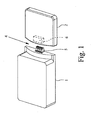
- FIG. 1 is an electrical connection and junction box according to a preferred embodiment of the invention in a perspective view can be seen, which has a housing 1 and a pin 2.
- a so-called solar can so to a box for connecting and connecting multiple solar cells of a solar cell module, including with bypass diodes.
- the housing 1 lines not shown can be fed, for. B. through a side wall or through the bottom of the housing 1 therethrough.
- connection options typically in the form of not shown terminals, provided.
- An interconnection which can be achieved with the connection possibilities which are typically present in the form of terminals is shown by way of example in FIG. 2.
- the plug-in module 2 has, as also shown in FIG. 2, diodes 3, which serve as bypass diodes for solar cells of a solar cell module.
- connection module 3 can be attached to the housing 1 by means of a plug connection 4.
- the connector 4 consists of a provided on the housing 1 connector 5 and a connector 5 corresponding socket 6 on the connection module 2. About this connector 4 those line connections from the housing 1 are guided in the connection module 2, which must be connected to the diodes 3 as can be seen in detail from FIG. 2.
- the connector 4 with connector 5 and 6 socket is designed such that the connection module 2 is simply plugged onto the housing 1, without having to use a tool.
- plug 5 and socket 6 of the connector 4 can be readily formed so that the achieved connection between the housing 1 and the connection module 2 is so stable that no further means for fixing and holding the connection module 2 are provided on the housing 1 have to.
- a non-illustrated adapter plug can be provided between the housing 1 and the connection module 2.
- Such an intermediary is typically designed such that it is provided on the side of the housing 1 with a socket which corresponds to the socket 6 of the connection module 2, and on its side facing the connection module 2 side is provided with a plug which the plug 5 of the housing. 1 equivalent.
- the adapter plug simultaneously or alternatively has a diagnostic connection for an external measuring device and a measuring line connection for connecting a measuring line. This makes it easy to carry out various verification procedures, namely, namely, it is possible to check whether the diodes 3 are still fully functional and whether the individual solar cells or rows of solar cells operate in accordance with regulations.
- the diodes 3 are embedded in the connection module 2 in a Vergusskar, in such a way that this Vergussstoff is applied directly to the diodes 3 and also has complete contact with the inner walls of the connection module 2. With the help of this Vergussffens it is achieved that the heat generated in the diodes 3 can be effectively dissipated to the outside of the environment of the connection module 2.
Landscapes
- Photovoltaic Devices (AREA)
- Details Of Connecting Devices For Male And Female Coupling (AREA)
- Coupling Device And Connection With Printed Circuit (AREA)
Description
- Die Erfindung betrifft eine elektrische Anschluß- und Verbindungsdose zum Anschluß von Solarzellen eines Solarzellenmoduls, mit einem Gehäuse, zum Anschließen und Verbinden in das Gehäuse eingeführter Leitungen miteinander bzw. mit in dem Gehäuse vorgesehenen elektrischen oder/und elektronischen Einrichtungen.
- Solche elektrischen Anschluß- und Verbindungsdosen sind aus dem Stand der Technik in vielfältiger Ausgestaltung bekannt wie z.B. aus
US 2002/0193001 A . - Da die Ausgangsspannung einzelner Solarzellen im allgemeinen zu gering ist, um elektrische Geräte, wie Haushaltsgeräte oder ähnliches, zu betreiben, werden mehrere Solarzellen zu Solarzellenmodulen zusammengeschaltet. Dabei besteht einerseits die Möglichkeit der Reihenschaltung und andererseits die Möglichkeit der Parallelschaltung der Solarzellen im Solarzellenmodul. Durch ein Parallelschalten der Solarzellen addieren sich die einzelnen Ströme der Solarzellen zu einem Gesamtstrom. Dabei sollten die parallelgeschalteten Solarzellen allerdings im wesentlichen die gleichen physikalischen Eigenschaften haben, so daß sich in der Praxis das Parallelschalten von Solarzellen kaum durchgesetzt hat, insbesondere auch da eine einzelne Solarzelle bereits einen Strom von einigen Ampere liefern kann.
- Bei der Zusammenstellung von Solarzellenmodulen mit einzelnen Solarzellen werden diese daher häufig in Reihe geschaltet. Ein Problem kann sich dabei jedoch dann ergeben, wenn ein Solarzellenmodul partiell abgeschattet wird, also eine Solarzelle oder einzelne Solarzellen des Solarzellenmoduls weniger oder gar keine Sonnenbestrahlung erhalten. Der Grund für eine verringerte Sonnenbestrahlung kann z. B. in einer Verschmutzung der Solarzellen oder in Schattenwürfe von Bäumen, Gebäudeeinrichtungen oder Gebäuden selbst liegen.
- Im Gegensatz zu einer Abschattung des Solarmoduls gleichmäßig über seine gesamte Fläche, die nur zu einer Leistungsverringerung insgesamt führt, ergibt sich bei einer partiellen Abschattung folgendes Problem: Durch die in Reihe geschalteten Solarzellen des Solarzellenmoduls fließt ein gemeinsamer Strom, wobei jede einzelne Solarzelle mit ihrer jeweiligen Spannung zur Gesamtspannung des Solarzellenmoduls beiträgt. Wird nun eine Solarzelle abgeschattet, so erzeugt diese keine Spannung mehr und setzt dem Stromfluß im Solarzellenmodul praktisch eine Diode in Sperrichtung entgegen. Dies bedeutet jedoch, daß das gesamte Modul keinen Strom mehr liefern kann, so daß die gesamte Funktion des Solarmoduls beeinträchtigt ist.
- Ferner gilt, daß an der abgeschatteten Solarzelle eine Spannung anliegt, die abhängig ist von der Position der abgeschatteten Solarzelle in der Reihenschaltung. Ist diese an der abgeschatteten Solarzelle anliegende Spannung größer als ihre Sperrspannung, so wird es in der Solarzelle zu einem Durchschlag und damit zu einer dauerhaften Beschädigung kommen.
- Selbst wenn es zu keiner Beschädigung der Solarzelle durch einen Durchschlag kommen sollte, wird in einer abgeschatteten Solarzelle eine große Verlustleistung umgesetzt, so daß sich die abgeschattete Solarzelle aufheizt. Auch eine solche Aufheizung kann zu Beschädigungen an der abgeschatteten Solarzelle sowie an den ihr benachbarten Solarzellen führen.
- Um die mit teilweise abgeschatteten Solarzellen verbundene Problematik zu vermeiden, werden häufig Dioden, sogenannte Bypass-Dioden, verwendet, die antiparallel zu den Solarzellen geschaltet werden. Auf diese Weise wird erreicht, daß eine abgeschattete Solarzelle zwar keinen Anteil mehr zur Gesamtspannung des Solarzellenmoduls leistet, der Stromfluß jedoch trotzdem erhalten bleibt. Das Solarzellenmodul zeigt somit lediglich eine verminderte Betriebsspannung, fällt jedoch nicht vollständig aus. Außerdem wird in der abgeschatteten Solarzelle keine Leistung mehr umgesetzt, so daß eine Beschädigung der abgeschatteten Solarzelle vermieden werden kann.
- Grundsätzlich könnte jeder Solarzelle eines Solarzellenmoduls genau eine Diode zugeordnet sein. Häufig wird jedoch so vorgegangen, daß eine Mehrzahl hintereinandergeschalteter Solarzellen jeweils durch eine gemeinsame Diode abgesichert wird.
- Elektrische Anschluß- und Verbindungsdosen, die für Solarzellenmodule verwendet werden, weisen somit im allgemeinen auch immer eine Mehrzahl von Bypass-Dioden auf. Damit ist jedoch das Problem verbunden, daß die für Solarzellenmodule verwendeten elektrischen Anschluß- und Verbindungsdosen jeweils so zugänglich sein müssen, daß beschädigte Dioden ausgetauscht werden können. Darüber hinaus kommt es durch die in den Bypass-Dioden umgesetzte Leistung zu einer nicht unerheblichen Erwärmung der für Solarzellenmodule verwendeten elektrischen Anschluß- und Verbindungsdosen.
- Aufgrund der zuvor geschilderten Problematik ist es die Aufgabe der Erfindung, eine für den Anschluß von Solarzellenmodulen vorgesehene elektrische Anschluß- und Verbindungsdose anzugeben, die ein einfaches Austauschen darin vorgesehener elektrischer oder/und elektronischer Einrichtungen, wie defekter Bypass-Dioden, gewährleistet und darüber hinaus vorzugsweise im Betrieb eine nur geringe Erwärmung zeigt.
- Diese Aufgabe ist durch die Merkmalskombination des kennzeichnenden Teils des Anspruchs 1 gelöst.
- Ausgehend von der eingangs beschriebenen elektrischen Anschluß- und Verbindungsdose ist die zuvor hergeleitete und aufgezeigte Aufgabe der Erfindung dadurch gelöst, daß ein elektrische oder/und elektronische Einrichtungen aufweisendes Ansteckmodul vorgesehen ist, das mittels einer einen Stecker und eine Buchse umfassenden Steckverbindung an das Gehäuse angesteckt ist, so daß die elektrischen oder/und elektronischen Einrichtungen des Ansteckmoduls mit den in dem Gehäuse vorgesehenen Leitungen bzw. elektrischen oder/und elektronischen Einrichtungen verbunden sind, wobei die elektrischen oder/und elektromischen Einrichtungen des Ansteckmoduls eine Bypass-Diode für die Solarzellen umfassen.
- Erfindungsgemäß wird also ein von dem Gehäuse der elektrischen Anschlußund Verbindungsdose verschiedenes Ansteckmodul vorgesehen, das elektrische Einrichtungen, wie Dioden, aufweisen kann. Dies ist insofern vorteilhaft, als daß zum Austausch der elektrischen oder/und elektronischen Einrichtungen des Ansteckmoduls, also z. B. von Bypass-Dioden für Solarzellen eines Solarzellenmoduls, das Gehäuse der elektrischen Anschluß- und Verbindungsdose nicht mehr geöffnet werden muß. Vielmehr kann das Ansteckmodul, das eine defekte elektrische oder/und elektronische Einrichtung, also z. B. eine defekte Bypass-Diode aufweist, einfach abgezogen und durch ein neues Ansteckmodul ersetzt werden, das einfach wieder an das Gehäuse angesteckt werden kann.
- Weiterhin gilt, daß durch das separate Vorsehen des Ansteckmoduls durch die in dem Ansteckmodul vorgesehenen elektrischen oder/und elektronischen Einrichtungen erzeugte Wärme nur zu ganz geringen Teilen auf das Gehäuse der elektrischen Anschluß- und Verbindungsdose übergeht. Im Vergleich mit dem Stand der Technik kann somit eine Erwärmung der elektrischen Anschluß- und Verbindungsdose ganz erheblich verringert werden.
- Grundsätzlich kann das Ansteckmodul mittels der Steckverbindung direkt mit dem Gehäuse verbunden sein, wobei als Steckverbindung z. B. ein an dem Gehäuse der elektrischen Anschluß- und Verbindungsdose vorgesehener Stecker und eine mit diesem Stecker zusammenwirkende Buchse am Ansteckmodul vorgesehen sein kann. Gemäß einer bevorzugten Weiterbildung der Erfindung ist vorgesehen, daß zwischen dem Gehäuse und dem Ansteckmodul ein Zwischenstecker vorgesehen ist. Dabei gilt sowohl für ein direktes Anstecken des Ansteckmoduls an das Gehäuse der elektrischen Anschluß- und Verbindungsdose als auch für ein Anstecken des Ansteckmoduls über ein zwischen dem Ansteckmodul und dem Gehäuse vorgesehenen Zwischenstecker, daß zwischen Gehäuse und Ansteckmodul bzw. Gehäuse, Zwischenstecker und Ansteckmodul keine weiteren Leitungen vorgesehen sind, Gehäuse und Ansteckmodul bzw. Gehäuse, Zwischenstecker und Ansteckmodul also direkt miteinander verbunden und zusammengesteckt sind.
- Mit einem gemäß einer bevorzugten Weiterbildung der Erfindung vorgesehenen Zwischenstecker sind verschiedene Vorteile verbunden:
- So kann ein solcher Zwischenstecker nämlich einen Diagnoseanschluß für ein externes Meßgerät aufweisen. Damit wird die Möglichkeit geschaffen, über die elektrische Anschluß- und Verbindungsdose angeschlossene bzw. verbundene Einrichtungen im laufenden Betrieb zu überprüfen.
- Alternativ oder zusätzlich dazu kann vorgesehen sein, daß der Zwischenstekker einen Meßleitungsanschluß zum Anschließen einer Meßleitung aufweist. Damit kann ein Meß- oder Anzeigegerät auch entfernt von der elektrischen Anschluß- und Verbindungsdose angeordnet werden, so daß zum Überprüfen der mittels der elektrischen Anschluß- und Verbindungsdose angeschlossenen bzw. verbundenen elektrischen Einrichtungen nicht direkt an der elektrischen Anschluß- und Verbindungsdose gemessen werden muß. Gegenüber fest verbundenen Leitungen zum Überprüfen oder Überwachen der über die elektrische Anschluß- und Verbindungsdose angeschlossenen bzw. verbundenen elektrischen oder/und elektronischen Einrichtungen weist ein solcher Zwischenstecker eine höhere Flexibilität auf, insbesondere kann der Zwischenstecker nämlich ohne weiteres wieder von der elektrischen Anschluß- und Verbindungsdose entfernt werden, so daß er dort im normalen Betrieb nicht weiter stört.
- Grundsätzlich können die elektrischen oder/und elektronischen Einrichtungen in dem Ansteckmodul frei, z. B. auf einer Platine, angeordnet sein. Gemäß einer bevorzugten Weiterbildung der Erfindung ist jedoch vorgesehen, daß die elektrischen oder/und elektronischen Einrichtungen in dem Ansteckmodul in ein Vergußmittel eingegossen sind. Insbesondere kommt ein Vergießen in ein Kunstharzmittel in Betracht, wie auch aus anderen Bereichen bei elektrischen Schaltungen bekannt.
- Ein solches Vergießen der elektrischen oder/und elektronischen Einrichtungen in dem Ansteckmodul hat mehrere Vorteile:
- Durch das direkt an den elektrischen oder/und elektronischen Einrichtungen anliegende Vergußmittel kann die in den elektrischen oder/und elektronischen Einrichtungen entstehende Wärme besser von diesen abgeführt werden, als wenn die elektrischen oder/und elektronischen Einrichtungen lediglich mit der in dem Ansteckmodul vorhandenen Umgebungsluft in Berührung stünden. Außerdem schützt das Vergußmittel die elektrischen oder/und elektronischen Einrichtungen vor äußeren Einwirkungen, insbesondere nämlich mechanischen Belastungen oder der Auswirkung von Nässe und Feuchtigkeit.
- Wie weiter oben schon angedeutet, ist die erfindungsgemäße elektrische Anschluß- und Verbindungsdose zum Anschluß von Solarzellen eines Solarzellenmoduls vorgesehen. Die elektrische Anschluß- und Verbindungsdose ist mittels des Gehäuses an dem Solarzellenmodul oder einem Dach befestigt. Das Ansteckmodul ist werkzeugfrei von dem Gehäuse lösbare. Schließlich gilt weiterhin, daß das Ansteckmodul vorzugsweise eine Mehrzahl von Bypass-Dioden für die Solarzellen des Solarzellenmoduls aufweist. Damit wird ein einfacher Wechsel des Ansteckmoduls zum Ersatz defekter Bypass-Dioden ermöglicht, ohne das Gehäuse der elektrischen Anschluß- und Verbindungsdose öffnen zu müssen und ohne ein Werkzeug zu verwenden.
- Sind die Bypass-Dioden in dem Ansteckmodul ferner gemäß einer bevorzugten Weiterbildung der Erfindung, wie weiter oben schon angedeutet, in ein Vergußmittel eingegossen, so wird darüber hinaus die in den Bypass-Dioden umgesetzte Leistung, die zu einer Erwärmung der Bypass-Dioden fiihrt, gut nach außen abgeführt.
- Im einzelnen gibt es nun eine Vielzahl von Möglichkeiten, die Erfindung weiter auszugestalten und weiterzubilden. Dazu wird auf die den unabhängigen Patentansprüchen nachgeordneten Patentansprüche sowie auf die nachfolgende detaillierte Beschreibung eines bevorzugten Ausführungsbeispiels der Erfindung unter Bezugnahme auf die Zeichnung verwiesen. In der Zeichnung zeigt
- Fig. 1
- eine elektrische Anschluß- und Verbindungsdose gemäß einem bevorzugten Ausführungsbeispiel der Erfindung in perspektivischer Ansicht und
- Fig. 2
- die elektrische Anschluß- und Verbindungsdose gemäß dem bevorzugten Ausführungsbeispiel der Erfindung mit ihrer elektrischen Verschaltung.
- Aus Fig. 1 ist eine elektrische Anschluß- und Verbindungsdose gemäß einem bevorzugten Ausführungsbeispiel der Erfindung in perspektivischer Ansicht ersichtlich, das ein Gehäuse 1 sowie ein Ansteckmodul 2 aufweist. Bei der vorliegend beschriebenen elektrischen Anschluß- und Verbindungsdose gemäß dem bevorzugten Ausführungsbeispiel der Erfindung handelt es sich um eine sogenannte Solardose, also um eine Dose zum Anschließen und Verbinden mehrerer Solarzellen eines Solarzellenmoduls, unter anderem mit Bypass-Dioden.
- Dazu sind dem Gehäuse 1 nicht weiter dargestellte Leitungen zuführbar, z. B. durch eine Seitenwand oder durch den Boden des Gehäuses 1 hindurch. In dem Gehäuse 1 sind Anschlußmöglichkeiten, typischerweise in Form nicht weiter dargestellter Anschlußklemmen, vorgesehen. Eine mit den typischerweise in Form von Anschlußklemmen vorliegenden Anschlußmöglichkeiten erzielbare Verschaltung ist exemplarisch aus Fig. 2 ersichtlich. Das Ansteckmodul 2 weist, wie ebenfalls aus Fig. 2 ersichtlich, Dioden 3 auf, die als Bypass-Dioden für Solarzellen eines Solarzellenmoduls dienen.
- Das Anschlußmodul 3 ist mittels einer Steckverbindung 4 an das Gehäuse 1 ansteckbar. Die Steckverbindung 4 besteht aus einem an dem Gehäuse 1 vorgesehenen Stecker 5 und einer diesem Stecker 5 entsprechenden Buchse 6 am Anschlußmodul 2. Über diese Steckverbindung 4 werden diejenigen Leitungsverbindungen aus dem Gehäuse 1 in das Anschlußmodul 2 geführt, die mit den Dioden 3 verbunden werden müssen, wie im Detail aus Fig. 2 ersichtlich.
- Die Steckverbindung 4 mit Stecker 5 und Buchse 6 ist derart ausgebildet, daß das Anschlußmodul 2 einfach auf das Gehäuse 1 aufsteckbar ist, ohne ein Werkzeug verwenden zu müssen. Darüber hinaus können Stecker 5 und Buchse 6 der Steckverbindung 4 ohne weiteres derart ausgebildet werden, daß die erzielte Verbindung zwischen dem Gehäuse 1 und dem Anschlußmodul 2 so stabil ist, daß keine weiteren Einrichtungen zur Befestigung und zum Halten des Anschlußmoduls 2 am Gehäuse 1 vorgesehen werden müssen.
- Zwischen dem Gehäuse 1 und dem Anschlußmodul 2 kann ein nicht weiter dargestellter Zwischenstecker vorgesehen werden. Ein solcher Zwischenstekker ist dabei typischerweise derart ausgebildet, daß er auf der Seite des Gehäuses 1 mit einer Buchse versehen ist, die der Buchse 6 des Anschlußmoduls 2 entspricht, und auf seiner dem Anschlußmodul 2 zugewandten Seite mit einem Stecker versehen ist, der dem Stecker 5 des Gehäuses 1 entspricht. Ferner weist der Zwischenstecker gleichzeitig oder alternativ einen Diagnoseanschluß für ein externes Meßgerät und einen Meßleitungsanschluß zum Anschließen einer Meßleitung auf. Damit lassen sich auf einfache Weise verschiedene Überprüfungsverfahren durchführen, unter anderem läßt sich nämlich prüfen, ob die Dioden 3 noch voll funktionsfähig sind und ob die einzelnen Solarzellen bzw. Reihen von Solarzellen vorschriftsmäßig arbeiten.
- Gemäß dem vorliegend beschriebenen bevorzugten Ausführungsbeispiel der Erfindung ist ferner vorgesehen, daß die Dioden 3 im Anschlußmodul 2 in ein Vergußmittel eingegossen sind, und zwar derart, daß dieses Vergußmittel direkt an den Dioden 3 anliegt und außerdem vollständigen Kontakt zu den Innenwänden des Anschlußmoduls 2 aufweist. Mit Hilfe dieses Vergußmittels wird erreicht, daß die in den Dioden 3 entstehende Wärme effektiv nach außen an die Umgebung des Anschlußmoduls 2 abgeführt werden kann.
Claims (5)
- Elektrische Anschluß- und Verbindungsdose zum Anschluß von Solarzellen eines Solarzellenmoduls, mit einem Gehäuse (1), zum Anschließen und Verbinden in das Gehäuse (1) eingeführter Leitungen miteinander bzw. mit in dem Gehäuse (1) vorgesehenen elektrischen oder/und elektronischen Einrichtungen, dadurch gekennzeichnet, daß ein elektrische oder/und elektronische Einrichtungen aufweisendes Ansteckmodul (2) vorgesehen ist, das mittels einer einen Stecker (5) und eine Buchse (6) umfassenden Steckverbindung (4) an das Gehäuse (1) angesteckt ist, so daß die elektrischen oder/und elektronischen Einrichtungen des Ansteckmoduls (2) mit den in dem Gehäuse (1) vorgesehenen Leitungen bzw. elektrischen oder/und elektronischen Einrichtungen verbunden sind, wobei die elektrischen oder/und elektronischen Einrichtungen des Ansteckmoduls (2) eine Bypass-Diode (3) für die Solarzellen umfassen.
- Elektrische Anschluß- und Verbindungsdose nach Anspruch 1, dadurch gekennzeichnet, daß zwischen dem Gehäuse (1) und dem Ansteckmodul (2) ein Zwischenstecker vorgesehen ist.
- Elektrische Anschluß- und Verbindungsdose nach Anspruch 2, dadurch gekennzeichnet, daß der Zwischenstecker einen Diagnoseanschluß für ein externes Meßgerät oder/und einen Meßleitungsanschluß zum Anschließen einer Meßleitung aufweist.
- Elektrische Anschluß- und Verbindungsdose nach einem der Ansprüche 1 bis 3, dadurch gekennzeichnet, daß die elektrischen oder/und elektronischen Einrichtungen in dem Ansteckmodul (2) in ein Vergußmittel eingegossen sind.
- Elektrische Anschluß- und Verbindungsdose nach einem der Ansprüche 1 bis 4, dadurch gekennzeichnet, daß das Ansteckmodul (2) eine Mehrzahl von Bypass-Dioden (3) aufweist.
Applications Claiming Priority (2)
| Application Number | Priority Date | Filing Date | Title |
|---|---|---|---|
| DE10331780A DE10331780B4 (de) | 2003-07-11 | 2003-07-11 | Elektrische Anschluß- und Verbindungsdose |
| DE10331780 | 2003-07-11 |
Publications (3)
| Publication Number | Publication Date |
|---|---|
| EP1496577A2 EP1496577A2 (de) | 2005-01-12 |
| EP1496577A3 EP1496577A3 (de) | 2005-10-05 |
| EP1496577B1 true EP1496577B1 (de) | 2007-07-25 |
Family
ID=33441750
Family Applications (1)
| Application Number | Title | Priority Date | Filing Date |
|---|---|---|---|
| EP04012404A Expired - Lifetime EP1496577B1 (de) | 2003-07-11 | 2004-05-26 | Elektrische Anschluss- und Verbindungsdose |
Country Status (4)
| Country | Link |
|---|---|
| EP (1) | EP1496577B1 (de) |
| AT (1) | ATE368314T1 (de) |
| DE (2) | DE10331780B4 (de) |
| ES (1) | ES2290588T3 (de) |
Cited By (3)
| Publication number | Priority date | Publication date | Assignee | Title |
|---|---|---|---|---|
| EP2672527A1 (de) | 2012-06-07 | 2013-12-11 | Hanwha Q-CELLS GmbH | Solarmodul mit einer Steckeinrichtung |
| CN101779339B (zh) * | 2007-08-10 | 2015-11-25 | 泰科电子Amp有限责任公司 | 用于光电太阳能装置的电连接系统 |
| DE102015218526A1 (de) | 2015-09-25 | 2017-03-30 | Hanwha Q Cells Gmbh | Anschlussanordnung für ein Solarmodul |
Families Citing this family (15)
| Publication number | Priority date | Publication date | Assignee | Title |
|---|---|---|---|---|
| DE102004053942A1 (de) * | 2004-11-09 | 2006-05-11 | Solarwatt Solar-Systeme Gmbh | Anschlusseinheit für photovoltaische Solarmodule |
| DE102005012213B4 (de) * | 2005-01-26 | 2009-01-15 | G. Spelsberg Gmbh & Co. Kg | Anschlußschaltung |
| DE102005036153B4 (de) * | 2005-05-24 | 2007-03-22 | Fraunhofer-Gesellschaft zur Förderung der angewandten Forschung e.V. | Schutzschalteinrichtung für ein Solarmodul |
| DE102008057327B3 (de) * | 2008-11-14 | 2010-06-24 | Yamaichi Electronics Deutschland Gmbh | Solarpaneel, Verfahren zum Herstellen und Überbrückungsdose |
| DE102009004100A1 (de) * | 2009-01-08 | 2010-07-15 | Yamaichi Electronics Deutschland Gmbh | Solarpaneel und Verfahren |
| DE102009018360A1 (de) | 2009-04-23 | 2010-11-04 | Rena Gmbh | Verfahren und Vorrichtung zur elektrolytischen Behandlung von Solarzellen |
| CN102195695B (zh) * | 2010-03-02 | 2013-11-20 | 电信科学技术研究院 | 天线校准的方法及装置 |
| ITMI20110917A1 (it) * | 2011-05-23 | 2012-11-24 | Compel Electronics S P A | Scatola di giunzione per pannelli fotovoltaici |
| EP3213406A1 (de) * | 2014-10-28 | 2017-09-06 | Corner Star Limited | Fotovoltaikmodule mit externen bypass-dioden |
| US10404208B2 (en) | 2015-06-02 | 2019-09-03 | Ja Solar Usa Inc. | Apparatus and method of a universal module junction box |
| EP3304729B1 (de) * | 2015-06-02 | 2025-03-05 | Ja Solar USA | Vorrichtung eines universalanschlusskastens für module |
| CN107174753B (zh) | 2017-05-15 | 2019-09-03 | 中国医学科学院肿瘤医院 | 多机械臂式术中放射治疗装置 |
| CN109728487A (zh) * | 2017-10-30 | 2019-05-07 | 泰科电子(上海)有限公司 | 适配器 |
| CN112882162B (zh) | 2021-01-19 | 2024-11-29 | 武汉电信器件有限公司 | 一种光电连接器以及光电适配器 |
| DE102021125242A1 (de) | 2021-09-29 | 2023-03-30 | Weidmüller Interface GmbH & Co. KG | Photovoltaikmodul und Anschlussanordnung für ein Photovoltaikmodul |
Family Cites Families (9)
| Publication number | Priority date | Publication date | Assignee | Title |
|---|---|---|---|---|
| DE3319141A1 (de) * | 1982-06-08 | 1983-12-08 | The Singer Co., 06904 Stamford, Conn. | Leiterplatten-steckmodul |
| GB2183936A (en) * | 1985-12-06 | 1987-06-10 | Plessey Co Plc | Power supply adaptor |
| DE4027478A1 (de) * | 1990-08-30 | 1992-03-05 | Robert Dipl Ing Michaelides | Schaltungsaufbau und herstellungsverfahren |
| CH681338A5 (en) * | 1990-09-11 | 1993-02-26 | Comat Ag | Plug socket for relay or electronic circuit module - has termination section with internal contacts and plug-in element fitted to ends of lead wires |
| DE19507644A1 (de) * | 1995-03-04 | 1996-09-05 | Sitron Sparkuhle Gmbh | Lichtschrankeneinrichtung |
| DE19917597A1 (de) * | 1999-04-19 | 2000-10-26 | Siemens Ag | Installationssystem für Elektrokomponenten einer Niederspannungsverteileranlage |
| JP2003008042A (ja) * | 2001-06-18 | 2003-01-10 | Sumitomo Wiring Syst Ltd | 太陽電池モジュール接続方法 |
| DE20111776U1 (de) * | 2001-07-17 | 2002-11-28 | Luxmate Controls Gmbh, Dornbirn | Anschlußeinrichtung für die Hausleittechnik |
| JP2004014920A (ja) * | 2002-06-10 | 2004-01-15 | Sumitomo Wiring Syst Ltd | ケーブル連結部構造 |
-
2003
- 2003-07-11 DE DE10331780A patent/DE10331780B4/de not_active Expired - Fee Related
-
2004
- 2004-05-26 ES ES04012404T patent/ES2290588T3/es not_active Expired - Lifetime
- 2004-05-26 EP EP04012404A patent/EP1496577B1/de not_active Expired - Lifetime
- 2004-05-26 DE DE502004004419T patent/DE502004004419D1/de not_active Expired - Lifetime
- 2004-05-26 AT AT04012404T patent/ATE368314T1/de not_active IP Right Cessation
Cited By (4)
| Publication number | Priority date | Publication date | Assignee | Title |
|---|---|---|---|---|
| CN101779339B (zh) * | 2007-08-10 | 2015-11-25 | 泰科电子Amp有限责任公司 | 用于光电太阳能装置的电连接系统 |
| EP2672527A1 (de) | 2012-06-07 | 2013-12-11 | Hanwha Q-CELLS GmbH | Solarmodul mit einer Steckeinrichtung |
| DE102015218526A1 (de) | 2015-09-25 | 2017-03-30 | Hanwha Q Cells Gmbh | Anschlussanordnung für ein Solarmodul |
| DE102015218526B4 (de) | 2015-09-25 | 2023-05-25 | Hanwha Q Cells Gmbh | Anschlussanordnung für ein Solarmodul |
Also Published As
| Publication number | Publication date |
|---|---|
| DE10331780B4 (de) | 2005-06-09 |
| EP1496577A2 (de) | 2005-01-12 |
| DE10331780A1 (de) | 2005-03-03 |
| DE502004004419D1 (de) | 2007-09-06 |
| ATE368314T1 (de) | 2007-08-15 |
| EP1496577A3 (de) | 2005-10-05 |
| ES2290588T3 (es) | 2008-02-16 |
Similar Documents
| Publication | Publication Date | Title |
|---|---|---|
| EP1496577B1 (de) | Elektrische Anschluss- und Verbindungsdose | |
| DE10358140B4 (de) | Elektrische Anschluß- und Verbindungsdose für ein Solarzellenmodul | |
| DE102005025976B4 (de) | Elektrische Anschluß- und Verbindungsdose für ein Solarzellenmodul | |
| DE102005012213B4 (de) | Anschlußschaltung | |
| DE69302160T2 (de) | Ein kompakter optischer Verstärker mit unterschiedlichen Funktionen | |
| DE102009034239A1 (de) | Halbleitervorrichtung mit Stiftanschlüssen | |
| DE102008052348A1 (de) | Verbindungsvorrichtung zur Verbindung eines elektrischen Leiters mit einem Solarmodul und Verfahren zu ihrer Herstellung, sowie Solarmodul mit einer solchen Verbindungsvorrichtung | |
| DE102007020843A1 (de) | Paneldose | |
| DE102013100607A1 (de) | Wechselrichter mit zweiteiligem Gehäuse | |
| WO2006079503A2 (de) | Schutzschaltung mit strom-bypass fur ein solarzεllenmodul | |
| DE102007005436B4 (de) | Trägermodul für einen Wechselrichter | |
| DE102011052928A1 (de) | Anordnung mit einem Solarzellenmodul, einer Anschlussdose, einem Anschlussstecker und einer Anschlussleitung | |
| EP1672702B1 (de) | Elektrische Anschluss- und Verbindungsdose für ein Solarzellenmodul | |
| EP0263391B1 (de) | Vorrichtung zum Empfangen, Aufbereiten, Verwerten und Weiterleiten elektrischer Signale | |
| DE19704801C2 (de) | Netzbetriebener Elektromotor | |
| DE102005044939B4 (de) | Elektrische Anschlußdose | |
| DE202004020974U1 (de) | Elektrische Anschluß- und Verbindungsdose | |
| WO2022089947A1 (de) | Solarzellenmodul | |
| DE102014202350A1 (de) | Integrierte galvanisch getrennte Messvorrichtungen und Verfahren zumHerstellen von integrierten galvanisch getrennten Messvorrichtungen | |
| DE20107116U1 (de) | Einrichtung zur Energieversorgung von Feldgeräten | |
| WO2013023780A1 (de) | Verteilermessdose zur strangstrombestimmung in photovoltaikanlagen | |
| DE202010000710U1 (de) | Solarpaneel | |
| EP2267462A1 (de) | Adapterbaugruppe | |
| DE102007020845A1 (de) | Paneldose | |
| EP2482326A2 (de) | Leistungshalbleiterelement und Anordnung eines Leistungshalbleiterelements zu mindestens einer Solarzelle |
Legal Events
| Date | Code | Title | Description |
|---|---|---|---|
| PUAI | Public reference made under article 153(3) epc to a published international application that has entered the european phase |
Free format text: ORIGINAL CODE: 0009012 |
|
| AK | Designated contracting states |
Kind code of ref document: A2 Designated state(s): AT BE BG CH CY CZ DE DK EE ES FI FR GB GR HU IE IT LI LU MC NL PL PT RO SE SI SK TR |
|
| AX | Request for extension of the european patent |
Extension state: AL HR LT LV MK |
|
| PUAL | Search report despatched |
Free format text: ORIGINAL CODE: 0009013 |
|
| AK | Designated contracting states |
Kind code of ref document: A3 Designated state(s): AT BE BG CH CY CZ DE DK EE ES FI FR GB GR HU IE IT LI LU MC NL PL PT RO SE SI SK TR |
|
| AX | Request for extension of the european patent |
Extension state: AL HR LT LV MK |
|
| 17P | Request for examination filed |
Effective date: 20060206 |
|
| AKX | Designation fees paid |
Designated state(s): AT BE BG CH CY CZ DE DK EE ES FI FR GB GR HU IE IT LI LU MC NL PL PT RO SE SI SK TR |
|
| GRAP | Despatch of communication of intention to grant a patent |
Free format text: ORIGINAL CODE: EPIDOSNIGR1 |
|
| GRAS | Grant fee paid |
Free format text: ORIGINAL CODE: EPIDOSNIGR3 |
|
| GRAA | (expected) grant |
Free format text: ORIGINAL CODE: 0009210 |
|
| AK | Designated contracting states |
Kind code of ref document: B1 Designated state(s): AT BE BG CH CY CZ DE DK EE ES FI FR GB GR HU IE IT LI LU MC NL PL PT RO SE SI SK TR |
|
| REG | Reference to a national code |
Ref country code: GB Ref legal event code: FG4D Free format text: NOT ENGLISH |
|
| REG | Reference to a national code |
Ref country code: CH Ref legal event code: EP |
|
| REG | Reference to a national code |
Ref country code: IE Ref legal event code: FG4D Free format text: LANGUAGE OF EP DOCUMENT: GERMAN |
|
| REF | Corresponds to: |
Ref document number: 502004004419 Country of ref document: DE Date of ref document: 20070906 Kind code of ref document: P |
|
| REG | Reference to a national code |
Ref country code: SE Ref legal event code: TRGR |
|
| PG25 | Lapsed in a contracting state [announced via postgrant information from national office to epo] |
Ref country code: FI Free format text: LAPSE BECAUSE OF FAILURE TO SUBMIT A TRANSLATION OF THE DESCRIPTION OR TO PAY THE FEE WITHIN THE PRESCRIBED TIME-LIMIT Effective date: 20070725 Ref country code: BG Free format text: LAPSE BECAUSE OF FAILURE TO SUBMIT A TRANSLATION OF THE DESCRIPTION OR TO PAY THE FEE WITHIN THE PRESCRIBED TIME-LIMIT Effective date: 20071025 Ref country code: PT Free format text: LAPSE BECAUSE OF FAILURE TO SUBMIT A TRANSLATION OF THE DESCRIPTION OR TO PAY THE FEE WITHIN THE PRESCRIBED TIME-LIMIT Effective date: 20071226 Ref country code: NL Free format text: LAPSE BECAUSE OF FAILURE TO SUBMIT A TRANSLATION OF THE DESCRIPTION OR TO PAY THE FEE WITHIN THE PRESCRIBED TIME-LIMIT Effective date: 20070725 |
|
| NLV1 | Nl: lapsed or annulled due to failure to fulfill the requirements of art. 29p and 29m of the patents act | ||
| REG | Reference to a national code |
Ref country code: ES Ref legal event code: FG2A Ref document number: 2290588 Country of ref document: ES Kind code of ref document: T3 |
|
| GBV | Gb: ep patent (uk) treated as always having been void in accordance with gb section 77(7)/1977 [no translation filed] |
Effective date: 20070725 |
|
| PG25 | Lapsed in a contracting state [announced via postgrant information from national office to epo] |
Ref country code: PL Free format text: LAPSE BECAUSE OF FAILURE TO SUBMIT A TRANSLATION OF THE DESCRIPTION OR TO PAY THE FEE WITHIN THE PRESCRIBED TIME-LIMIT Effective date: 20070725 |
|
| REG | Reference to a national code |
Ref country code: IE Ref legal event code: FD4D |
|
| EN | Fr: translation not filed | ||
| PG25 | Lapsed in a contracting state [announced via postgrant information from national office to epo] |
Ref country code: GR Free format text: LAPSE BECAUSE OF FAILURE TO SUBMIT A TRANSLATION OF THE DESCRIPTION OR TO PAY THE FEE WITHIN THE PRESCRIBED TIME-LIMIT Effective date: 20071026 Ref country code: DK Free format text: LAPSE BECAUSE OF FAILURE TO SUBMIT A TRANSLATION OF THE DESCRIPTION OR TO PAY THE FEE WITHIN THE PRESCRIBED TIME-LIMIT Effective date: 20070725 |
|
| PG25 | Lapsed in a contracting state [announced via postgrant information from national office to epo] |
Ref country code: GB Free format text: LAPSE BECAUSE OF FAILURE TO SUBMIT A TRANSLATION OF THE DESCRIPTION OR TO PAY THE FEE WITHIN THE PRESCRIBED TIME-LIMIT Effective date: 20070725 Ref country code: IE Free format text: LAPSE BECAUSE OF FAILURE TO SUBMIT A TRANSLATION OF THE DESCRIPTION OR TO PAY THE FEE WITHIN THE PRESCRIBED TIME-LIMIT Effective date: 20070725 Ref country code: SK Free format text: LAPSE BECAUSE OF FAILURE TO SUBMIT A TRANSLATION OF THE DESCRIPTION OR TO PAY THE FEE WITHIN THE PRESCRIBED TIME-LIMIT Effective date: 20070725 |
|
| PLBE | No opposition filed within time limit |
Free format text: ORIGINAL CODE: 0009261 |
|
| STAA | Information on the status of an ep patent application or granted ep patent |
Free format text: STATUS: NO OPPOSITION FILED WITHIN TIME LIMIT |
|
| PG25 | Lapsed in a contracting state [announced via postgrant information from national office to epo] |
Ref country code: RO Free format text: LAPSE BECAUSE OF FAILURE TO SUBMIT A TRANSLATION OF THE DESCRIPTION OR TO PAY THE FEE WITHIN THE PRESCRIBED TIME-LIMIT Effective date: 20070725 |
|
| 26N | No opposition filed |
Effective date: 20080428 |
|
| PG25 | Lapsed in a contracting state [announced via postgrant information from national office to epo] |
Ref country code: FR Free format text: LAPSE BECAUSE OF FAILURE TO SUBMIT A TRANSLATION OF THE DESCRIPTION OR TO PAY THE FEE WITHIN THE PRESCRIBED TIME-LIMIT Effective date: 20080321 |
|
| BERE | Be: lapsed |
Owner name: G. SPELSBERG G.M.B.H. & CO.KG Effective date: 20080531 |
|
| PG25 | Lapsed in a contracting state [announced via postgrant information from national office to epo] |
Ref country code: MC Free format text: LAPSE BECAUSE OF NON-PAYMENT OF DUE FEES Effective date: 20080531 |
|
| REG | Reference to a national code |
Ref country code: CH Ref legal event code: PL |
|
| PG25 | Lapsed in a contracting state [announced via postgrant information from national office to epo] |
Ref country code: CH Free format text: LAPSE BECAUSE OF NON-PAYMENT OF DUE FEES Effective date: 20080531 Ref country code: LI Free format text: LAPSE BECAUSE OF NON-PAYMENT OF DUE FEES Effective date: 20080531 |
|
| PG25 | Lapsed in a contracting state [announced via postgrant information from national office to epo] |
Ref country code: BE Free format text: LAPSE BECAUSE OF NON-PAYMENT OF DUE FEES Effective date: 20080531 |
|
| PG25 | Lapsed in a contracting state [announced via postgrant information from national office to epo] |
Ref country code: EE Free format text: LAPSE BECAUSE OF FAILURE TO SUBMIT A TRANSLATION OF THE DESCRIPTION OR TO PAY THE FEE WITHIN THE PRESCRIBED TIME-LIMIT Effective date: 20070725 |
|
| PG25 | Lapsed in a contracting state [announced via postgrant information from national office to epo] |
Ref country code: SI Free format text: LAPSE BECAUSE OF FAILURE TO SUBMIT A TRANSLATION OF THE DESCRIPTION OR TO PAY THE FEE WITHIN THE PRESCRIBED TIME-LIMIT Effective date: 20070725 |
|
| PG25 | Lapsed in a contracting state [announced via postgrant information from national office to epo] |
Ref country code: CY Free format text: LAPSE BECAUSE OF FAILURE TO SUBMIT A TRANSLATION OF THE DESCRIPTION OR TO PAY THE FEE WITHIN THE PRESCRIBED TIME-LIMIT Effective date: 20070725 |
|
| PG25 | Lapsed in a contracting state [announced via postgrant information from national office to epo] |
Ref country code: AT Free format text: LAPSE BECAUSE OF NON-PAYMENT OF DUE FEES Effective date: 20080526 |
|
| PG25 | Lapsed in a contracting state [announced via postgrant information from national office to epo] |
Ref country code: LU Free format text: LAPSE BECAUSE OF NON-PAYMENT OF DUE FEES Effective date: 20080526 Ref country code: HU Free format text: LAPSE BECAUSE OF FAILURE TO SUBMIT A TRANSLATION OF THE DESCRIPTION OR TO PAY THE FEE WITHIN THE PRESCRIBED TIME-LIMIT Effective date: 20080126 |
|
| PG25 | Lapsed in a contracting state [announced via postgrant information from national office to epo] |
Ref country code: TR Free format text: LAPSE BECAUSE OF FAILURE TO SUBMIT A TRANSLATION OF THE DESCRIPTION OR TO PAY THE FEE WITHIN THE PRESCRIBED TIME-LIMIT Effective date: 20070725 |
|
| PG25 | Lapsed in a contracting state [announced via postgrant information from national office to epo] |
Ref country code: IT Free format text: LAPSE BECAUSE OF NON-PAYMENT OF DUE FEES Effective date: 20080531 |
|
| REG | Reference to a national code |
Ref country code: DE Ref legal event code: R081 Ref document number: 502004004419 Country of ref document: DE Owner name: GUENTHER SPELSBERG GMBH + CO. KG, DE Free format text: FORMER OWNER: G. SPELSBERG GMBH + CO. KG, 58579 SCHALKSMUEHLE, DE Effective date: 20120424 |
|
| PGFP | Annual fee paid to national office [announced via postgrant information from national office to epo] |
Ref country code: SE Payment date: 20120522 Year of fee payment: 9 |
|
| REG | Reference to a national code |
Ref country code: SE Ref legal event code: EUG |
|
| PG25 | Lapsed in a contracting state [announced via postgrant information from national office to epo] |
Ref country code: SE Free format text: LAPSE BECAUSE OF NON-PAYMENT OF DUE FEES Effective date: 20130527 |
|
| PGFP | Annual fee paid to national office [announced via postgrant information from national office to epo] |
Ref country code: CZ Payment date: 20150525 Year of fee payment: 12 Ref country code: ES Payment date: 20150527 Year of fee payment: 12 |
|
| PG25 | Lapsed in a contracting state [announced via postgrant information from national office to epo] |
Ref country code: CZ Free format text: LAPSE BECAUSE OF NON-PAYMENT OF DUE FEES Effective date: 20160526 |
|
| PG25 | Lapsed in a contracting state [announced via postgrant information from national office to epo] |
Ref country code: ES Free format text: LAPSE BECAUSE OF NON-PAYMENT OF DUE FEES Effective date: 20160527 |
|
| REG | Reference to a national code |
Ref country code: ES Ref legal event code: FD2A Effective date: 20180626 |
|
| PGFP | Annual fee paid to national office [announced via postgrant information from national office to epo] |
Ref country code: DE Payment date: 20200527 Year of fee payment: 17 |
|
| REG | Reference to a national code |
Ref country code: DE Ref legal event code: R119 Ref document number: 502004004419 Country of ref document: DE |
|
| PG25 | Lapsed in a contracting state [announced via postgrant information from national office to epo] |
Ref country code: DE Free format text: LAPSE BECAUSE OF NON-PAYMENT OF DUE FEES Effective date: 20211201 |