EP1496208B1 - Dispositif de guidage en rotation d'aubes à calage variable dans une turbomachine - Google Patents
Dispositif de guidage en rotation d'aubes à calage variable dans une turbomachine Download PDFInfo
- Publication number
- EP1496208B1 EP1496208B1 EP04291720.3A EP04291720A EP1496208B1 EP 1496208 B1 EP1496208 B1 EP 1496208B1 EP 04291720 A EP04291720 A EP 04291720A EP 1496208 B1 EP1496208 B1 EP 1496208B1
- Authority
- EP
- European Patent Office
- Prior art keywords
- vanes
- casing
- pivots
- radially
- stationary element
- Prior art date
- Legal status (The legal status is an assumption and is not a legal conclusion. Google has not performed a legal analysis and makes no representation as to the accuracy of the status listed.)
- Expired - Lifetime
Links
- 239000000463 material Substances 0.000 claims description 3
- 239000002783 friction material Substances 0.000 description 3
- 238000010438 heat treatment Methods 0.000 description 3
- 229910000906 Bronze Inorganic materials 0.000 description 1
- 239000010974 bronze Substances 0.000 description 1
- KUNSUQLRTQLHQQ-UHFFFAOYSA-N copper tin Chemical compound [Cu].[Sn] KUNSUQLRTQLHQQ-UHFFFAOYSA-N 0.000 description 1
- 230000006378 damage Effects 0.000 description 1
- 230000006866 deterioration Effects 0.000 description 1
- 238000003754 machining Methods 0.000 description 1
- 238000004519 manufacturing process Methods 0.000 description 1
Images


Classifications
-
- F—MECHANICAL ENGINEERING; LIGHTING; HEATING; WEAPONS; BLASTING
- F01—MACHINES OR ENGINES IN GENERAL; ENGINE PLANTS IN GENERAL; STEAM ENGINES
- F01D—NON-POSITIVE DISPLACEMENT MACHINES OR ENGINES, e.g. STEAM TURBINES
- F01D17/00—Regulating or controlling by varying flow
- F01D17/10—Final actuators
- F01D17/12—Final actuators arranged in stator parts
- F01D17/14—Final actuators arranged in stator parts varying effective cross-sectional area of nozzles or guide conduits
- F01D17/16—Final actuators arranged in stator parts varying effective cross-sectional area of nozzles or guide conduits by means of nozzle vanes
- F01D17/162—Final actuators arranged in stator parts varying effective cross-sectional area of nozzles or guide conduits by means of nozzle vanes for axial flow, i.e. the vanes turning around axes which are essentially perpendicular to the rotor centre line
Definitions
- the invention relates to a device for guiding rotation of variable pitch vanes in a turbomachine such as an airplane turbojet or turboprop engine, see GB-A-1505858 and US Patent 3496628 .
- these vanes are, at one of their ends, rotatably mounted on the casing of the turbomachine about radial axes relative to the axis of rotation of the rotor and comprise for this cylindrical shanks axial forming pivots guided in rotation in bearings which are mounted in cylindrical radial chimneys of the casing of the turbomachine.
- These bearings are generally formed by sleeves of low friction material, such as sintered bronze, for example.
- the axial casings of the housing have a limited length, so that the blades subjected to the forces exerted by the gas flows tend to incline obliquely to their axis of rotation, which causes wear of the guide bushes and internal cylindrical surfaces of the chimneys in which these sockets are mounted.
- This results in risks of seizure of the blade pivots and an increase in the forces that must be applied to these vanes to rotate around their axes of rotation. It also results in a risk of contact between the radially inner ends of these blades and the rotor of the turbomachine, and concomitant risks of deterioration, destruction and fire due to the intense heating produced by the friction of the ends of the blades. blades on the rotor.
- the object of the invention is in particular to avoid these drawbacks by better guiding in rotation of the pivots of the blades with variable pitch.
- a device for guiding rotation of blades with variable pitch in a turbomachine each comprising a pivot guided in rotation in a cylindrical chimney of a housing of the turbomachine and which is connected by a rod to a control ring surrounding the housing, characterized in that the pivot of each of these blades extends outside the housing beyond the chimney and has a radially external end guided in rotation by a fixed element outside the housing, and in that the rods are fixed on the pivots of the blades between the ends of these pivots and support and center the control ring away from the housing.
- the improvement of the rotation guidance of the variable-pitch blades is due to the increase in the length over which the blade pivots are guided, which reduces the recessing forces of the blade pivots in their means of rotation. guidance, facilitates the driving of the blades in rotation about their axes and avoids any risk of contact and friction of the radially inner ends of the blades on the rotor of the turbomachine.
- the aforementioned fixed element is spaced radially from the casing, with respect to the axis of rotation of the turbomachine, by a distance which is greater than the corresponding dimension of the aforementioned cylindrical chimney, this distance being for example of the order of 10 cm.
- a corollary advantage of the invention is that this device reduces the length of cylindrical chimneys that are formed on the housing, which simplifies the manufacture and machining of the housing.
- Another corollary advantage of the invention is that the guide means of the blade pivots outside the housing are further away from the hot source formed by the flow of gas in the turbomachine and are therefore subjected to less heating. .
- control ring of these blades is supported and centered around the housing by means of the parts of the blade pivots which extend outside the housing, which avoids centering and supporting this ring directly on the casing of the turbomachine.
- control ring is substantially at the same temperature as the aforementioned fixed element and their thermal expansions are of the same order of magnitude, which improves the guidance of the control ring. This results in a reduction of the driving force of the variable pitch vanes, so that simpler and less expensive means of driving these vanes can be used.
- the aforementioned fixed element comprises means for rotating the pivots of several blades forming part of the same row of variable-pitch vanes.
- this fixed element may comprise means for rotating the pivots of all the blades of the same row of variable-pitch vanes.
- this fixed element comprises means for rotating the pivots of all the blades which are part of two successive rows of variable-pitch vanes.
- the aforementioned fixed element is annular in shape and extends around the housing about 360 degrees.
- It is preferably monobloc and also reinforces the rigidity of the casing of the turbomachine.
- this fixed element is formed of several consecutive annular segments or not which are each fixed on the housing.
- the reference 10 designates a turbomachine casing, of generally cylindrical shape and centered on the axis of rotation of a rotor of this turbomachine.
- This comprises one or more stages of rectifiers which are formed by blades 12 for guiding the gas flow, these vanes being rotatably mounted on the housing 10 about radial axes with respect to the axis of rotation of the rotor, only their radially outer portion or “blade root" being shown in the drawings.
- These blades 12 comprise a cylindrical axial shank 14 which extends inside a radial cylindrical chimney 16 of the casing 10 and which has a radially outer end portion 18 which extends beyond the chimney 16 and which is guided in rotation in a cylindrical orifice 20 of a fixed element 22 which externally surrounds the housing 10, at a distance from the latter.
- the fixed element 22 comprises a cylindrical wall 24 centered on the axis of rotation of the rotor of the turbomachine and comprising the above-mentioned orifices 20 and fastening lugs 26 which extend from this cylindrical wall 24. in the direction of the housing and terminate in soles 28 receiving fastening screws 30 on the housing 10.
- the fixed member 22 may be of continuous or substantially continuous annular shape and extend about 360 degrees about the longitudinal axis of the housing.
- the brackets 26 are formed at regular intervals on the element 22 and when it is fixed on the housing, it reinforces the rigidity of the latter.
- the fixed element 22 may be formed of two semi-cylindrical elements which each extend about 180 degrees and which are fixed end to end on the housing 10.
- the fixed element 22 may be formed of several annular segments fixed end to end on the housing 10.
- the axial tails 14 of the vanes 12 are guided in the cylindrical chimneys 16 of the casing and in the cylindrical orifices of the fixed element 22 by means of plain bearings which consist for example of cylindrical bushes 32, 34 respectively, and washers. 36, 38 respectively, of low friction material.
- the washer 36 associated with the bushing 32 is inside the housing 10 while the washer 38 associated with the bushing 34 is radially outside the cylindrical portion 24 of the fixed element.
- the portion of the cylindrical axial tail of the blade which extends from the blade root 12 is relatively long and extends well beyond the cylindrical casing 16 of the casing, the increase of the guiding length cylindrical axial tails 14 of the blades being for example about 100 to 200% compared to the prior art thanks to the device according to the invention.
- cylindrical sleeve 34 and the washer 38 for guiding the blade pivot in the fixed element 22 are relatively remote from the casing 10, they are subjected to less heating than the sleeve 32 and the washer 36 and can therefore be made of a cheap material.
- the intermediate portion of the cylindrical axial shank 14 of each blade which extends between the cylindrical chimney 16 and the fixed element 22 advantageously serves to attach a connecting rod 40 to a control ring 42 which extends around of the housing 10 and which is itself associated with actuating means (not shown) for rotating it in one direction and the other around the longitudinal axis of the housing 10 to drive the blades 12 rotating around of their pivots 14.
- each link 40 is fixedly mounted at one end on the pivot 14 of a blade 12 and its other end is articulated on the control ring 42 around a radial axis materialized by a pin 44.
- control ring 42 is carried by the rods 40 which are themselves fixedly mounted on the pivots 14 of the blades 12, which avoids using other support means and centering the control ring 42 on the housing 10.
- control ring 42 is thus kept at a distance from the casing 10 and its thermal expansion will be comparable to that of the fixed element 22, which facilitates the guiding of this control ring 42 and simplifies its means of control. actuation.
- the same fixed element 22 serves to guide the vanes 12 in rotation in two consecutive rows of variable-pitch vanes whose pivots formed by the cylindrical axial shanks 14 are guided in cylindrical chimneys 16 of the casing and in cylindrical orifices of two lateral wings 48 of the fixed element 22 which extend on either side of a cylindrical wall 50 supported and fixed on the casing 10 by fixing lugs 52 regularly distributed around the longitudinal axis of the casing 10.
- the tabs 52 comprise at their radially inner and radially outer ends soles 54 by means of which they are fixed on the housing 10 and on the cylindrical portion 50 of the fixed element 22.
- the means for guiding rotation of the pivots 14 in the cylindrical bushes 16 of the housing and in the cylindrical orifices of the fixed element 22 are the same as those already described and shown in FIGS. figures 1 and 2 .
- the pivots 14 of the variable pitch vanes of each row are connected by links 40 to a control ring 42 which surrounds the housing 10 externally and which is supported and centered by the rods 40, themselves fixedly mounted on the pivots 14
- the two control rings 42 represented in figure 3 are parallel and located at the same distance from the longitudinal axis of the housing 10, the rods 40 of the two rows of variable-pitch vanes being oriented in the same direction so that the control ring 42 shown in the right part of the figure 3 is located under the cylindrical central portion 50 of the fixed element 22 in the vicinity of the fixing lugs 52 while the other control ring 42 shown in the left part of the figure 3 is outside the fixed element 22.
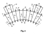
- the figure 4 schematically represents an embodiment variant in which radially inner pivots 56 of the blades 12 of the same row are guided in cylindrical bushes 58 carried by radially internal ring sectors 60, which extend around the axis of rotation in the extension of each other.
- Each internal sector 60 guides the internal pivots 56 of a number of blades 12, this number being for example about ten.
- the end vanes 12a of each group of vanes 12 carried by the same inner ring sector 60 have radially outer long pivots 14 whose outer ends are guided in bushes 34 of a fixed outer element 22 mentioned above.
- the outer pivots 14 of the blades 12 located between these end vanes 12a in each group are not extended outwards and are guided only in the cylindrical chimneys 16 of the housing 10, as shown.
- the end vanes 12a of each group may comprise a blade at each end, as shown, or several blades.
- end vanes 12a take up the efforts to embed the blades 12 of the group and can be reinforced, for example thickened, and / or made of a stronger material than the other blades of the group, which do not have to resume the aforementioned embedding forces.
Landscapes
- Engineering & Computer Science (AREA)
- Mechanical Engineering (AREA)
- General Engineering & Computer Science (AREA)
- Structures Of Non-Positive Displacement Pumps (AREA)
- Control Of Turbines (AREA)
- Turbine Rotor Nozzle Sealing (AREA)
Description
- L'invention concerne un dispositif de guidage en rotation d'aubes à calage variable dans une turbomachine telle qu'un turboréacteur ou un turbopropulseur d'avion, voir
GB-A-1505858 US-A-3496628 . - Dans les dispositifs de guidage connus, ces aubes sont, à l'une de leurs extrémités, montées à rotation sur le carter de la turbomachine autour d'axes radiaux par rapport à l'axe de rotation du rotor et comprennent pour cela des queues cylindriques axiales formant des pivots guidés en rotation dans des paliers qui sont montés dans des cheminées cylindriques radiales du carter de la turbomachine. Ces paliers sont en général formés par des douilles de matière à faible coefficient de frottement, telle que du bronze fritté par exemple.
- Les cheminées axiales du carter ont une longueur limitée, de sorte que les aubes soumises aux efforts exercés par les écoulements de gaz tendent à s'incliner en oblique par rapport à leur axe de rotation, ce qui provoque une usure des douilles de guidage et des surfaces cylindriques internes des cheminées dans lesquelles ces douilles sont montées. Il en résulte des risques de grippage des pivots d'aube et une augmentation des efforts qu'il faut appliquer à ces aubes pour les faire pivoter autour de leurs axes de rotation. Il en résulte également un risque de contact entre les extrémités radialement internes de ces aubes et le rotor de la turbomachine, et des risques concomitants de détérioration, de destruction et d'incendie en raison de l'échauffement intense produit par le frottement des extrémités des aubes sur le rotor.
- L'invention a notamment pour but d'éviter ces inconvénients grâce à un meilleur guidage en rotation des pivots des aubes à calage variable.
- Elle propose à cet effet un dispositif de guidage en rotation d'aubes à calage variable dans une turbomachine, ces aubes comprenant chacune un pivot guidé en rotation dans une cheminée cylindrique d'un carter de la turbomachine et qui est relié par une biellette à un anneau de commande entourant le carter, caractérisé en ce que le pivot de chacune de ces aubes s'étend à l'extérieur du carter au-delà de la cheminée et comporte une extrémité radialement externe guidée en rotation par un élément fixe extérieur au carter, et en ce que les biellettes sont fixées sur les pivots des aubes entre les extrémités de ces pivots et supportent et centrent l'anneau de commande à distance du carter.
- Dans ce dispositif, l'amélioration du guidage en rotation des aubes à calage variable est due à l'augmentation de la longueur sur laquelle les pivots des aubes sont guidés, ce qui réduit les efforts d'encastrement des pivots des aubes dans leurs moyens de guidage, facilite l'entraînement des aubes en rotation autour de leurs axes et évite tout risque de contact et de frottement des extrémités radialement internes des aubes sur le rotor de la turbomachine.
- L'élément fixe précité est écarté radialement du carter, par rapport à l'axe de rotation de la turbomachine, d'une distance qui est supérieure à la dimension correspondante de la cheminée cylindrique précitée, cette distance étant par exemple de l'ordre de 10 cm.
- Un avantage corollaire de l'invention est que ce dispositif permet de réduire la longueur des cheminées cylindriques qui sont formées sur le carter, ce qui simplifie la fabrication et l'usinage du carter.
- Un autre avantage corollaire de l'invention est que les moyens de guidage des pivots d'aubes à l'extérieur du carter sont plus éloignés de la source chaude formée par l'écoulement des gaz dans la turbomachine et sont donc soumis à un échauffement moindre.
- On peut en conséquence utiliser pour ces moyens de guidage des matières à faible coefficient de frottement qui sont meilleur marché.
- De plus, selon l'invention, l'anneau de commande de ces aubes est supporté et centré autour du carter au moyen des parties des pivots des aubes qui s'étendent à l'extérieur du carter, ce qui évite de centrer et de supporter cet anneau directement sur le carter de la turbomachine.
- En outre, l'anneau de commande se trouve sensiblement à la même température que l'élément fixe précité et leurs dilatations thermiques sont du même ordre de grandeur, ce qui améliore le guidage de l'anneau de commande. Il en résulte une réduction de l'effort d'entraînement des aubes à calage variable, de sorte que l'on peut utiliser des moyens plus simples et moins coûteux d'entraînement de ces aubes.
- Selon une autre caractéristique de l'invention, l'élément fixe précité comporte des moyens de guidage en rotation des pivots de plusieurs aubes faisant partie d'une même rangée d'aubes à calage variable.
- En variante, cet élément fixe peut comporter des moyens de guidage en rotation des pivots de toutes les aubes d'une même rangée d'aubes à calage variable.
- Dans une autre variante de réalisation, cet élément fixe comporte des moyens de guidage en rotation des pivots de toutes les aubes qui font partie de deux rangées successives d'aubes à calage variable.
- Dans une forme de réalisation, l'élément fixe précité est de forme annulaire et s'étend autour du carter sur 360 degrés environ.
- Il est alors de préférence monobloc et renforce également la rigidité du carter de la turbomachine.
- Dans une autre forme de réalisation, cet élément fixe est formé de plusieurs segments annulaires consécutifs ou non qui sont fixés chacun sur le carter.
- L'invention sera mieux comprise et d'autres caractéristiques, détails et avantages de celle-ci apparaîtront plus clairement à la lecture de la description qui suit, faite à titre d'exemple en référence aux dessins annexés dans lesquels :
- les
figures 1 et2 sont des vues schématiques partielles en perspective, à des échelles différentes, d'un premier mode de réalisation du dispositif selon l'invention ; - la
figure 3 est une vue schématique partielle en perspective d'une variante de réalisation de ce dispositif ; - la
figure 4 est une vue schématique partielle d'une variante de réalisation de l'invention. - Dans les
figures 1 et2 qui représentent un premier mode de réalisation de l'invention, la référence 10 désigne un carter de turbomachine, de forme globalement cylindrique et centré sur l'axe de rotation d'un rotor de cette turbomachine. - Celle-ci comprend un ou plusieurs étages de redresseurs qui sont formés par des aubes 12 de guidage de l'écoulement gazeux, ces aubes étant montées rotatives sur le carter 10 autour d'axes radiaux par rapport à l'axe de rotation du rotor, seule leur partie radialement externe ou "pied d'aube" étant représentée dans les dessins.
- Ces aubes 12 comprennent une queue axiale cylindrique 14 qui s'étend à l'intérieur d'une cheminée cylindrique radiale 16 du carter 10 et qui comporte une partie d'extrémité radialement externe 18 qui s'étend au-delà de la cheminée 16 et qui est guidée en rotation dans un orifice cylindrique 20 d'un élément fixe 22 qui entoure extérieurement le carter 10, à distance de ce dernier.
- Dans le mode de réalisation représenté, l'élément fixe 22 comporte une paroi cylindrique 24 centrée sur l'axe de rotation du rotor de la turbomachine et comportant les orifices 20 précités et des pattes de fixation 26 qui s'étendent depuis cette paroi cylindrique 24 en direction du carter et se terminent par des semelles 28 recevant des vis 30 de fixation sur le carter 10.
- L'élément fixe 22 peut être de forme annulaire continue ou sensiblement continue et s'étendre sur 360 degrés environ autour de l'axe longitudinal du carter. Les pattes 26 de fixation sont formées à intervalles réguliers sur l'élément 22 et quand celui-ci est fixé sur le carter, il renforce la rigidité de ce dernier.
- Dans une variante de réalisation, l'élément fixe 22 peut être formé de deux éléments semi-cylindriques qui s'étendent chacun sur 180 degrés environ et qui sont fixés bout à bout sur le carter 10.
- Dans une autre variante, l'élément fixe 22 peut être formé de plusieurs segments annulaires fixés bout à bout sur le carter 10.
- Les queues axiales 14 des aubes 12 sont guidées dans les cheminées cylindriques 16 du carter et dans les orifices cylindriques de l'élément fixe 22 au moyen de paliers lisses qui sont constitués par exemple par des douilles cylindriques 32, 34 respectivement, et par des rondelles 36, 38 respectivement, de matière à faible coefficient de frottement.
- Dans l'exemple représenté, la rondelle 36 associée à la douille 32 est à l'intérieur du carter 10 tandis que la rondelle 38 associée à la douille 34 est radialement à l'extérieur de la partie cylindrique 24 de l'élément fixe.
- Comme on le voit sur les
figures 1 et2 , la partie de la queue axiale cylindrique de l'aube qui s'étend depuis le pied d'aube 12 est relativement longue et s'étend largement au-delà de la cheminée cylindrique 16 du carter, l'augmentation de la longueur de guidage des queues axiales cylindriques 14 des aubes étant par exemple d'environ 100 à 200 % par rapport à la technique antérieure grâce au dispositif selon l'invention. - Comme la douille cylindrique 34 et la rondelle 38 de guidage en rotation du pivot d'aube dans l'élément fixe 22 sont relativement éloignées du carter 10, elles sont soumises à un échauffement moins important que la douille 32 et la rondelle 36 et peuvent donc être réalisées dans un matériau bon marché.
- La partie intermédiaire de la queue axiale cylindrique 14 de chaque aube qui s'étend entre la cheminée cylindrique 16 et l'élément fixe 22 sert avantageusement à la fixation d'une biellette 40 de liaison à un anneau de commande 42 qui s'étend autour du carter 10 et qui est lui-même associé à des moyens d'actionnement (non représentés) permettant de le faire tourner dans un sens et dans l'autre autour de l'axe longitudinal du carter 10 pour entraîner les aubes 12 en rotation autour de leurs pivots 14.
- De façon plus détaillée, chaque biellette 40 est montée fixement par une extrémité sur le pivot 14 d'une aube 12 et son autre extrémité est articulée sur l'anneau de commande 42 autour d'un axe radial matérialisé par une goupille 44.
- Un avantage du dispositif selon l'invention est que l'anneau de commande 42 est porté par les biellettes 40 qui sont elles-mêmes montées fixement sur les pivots 14 des aubes 12, ce qui évite d'utiliser d'autres moyens de support et de centrage de l'anneau de commande 42 sur le carter 10.
- Par ailleurs, l'anneau de commande 42 est ainsi maintenu à distance du carter 10 et ses dilations thermiques vont être comparables à celles de l'élément fixe 22, ce qui facilite le guidage de cet anneau de commande 42 et simplifie ses moyens d'actionnement.
- Dans la variante de réalisation représentée en
figure 3 , le même élément fixe 22 sert au guidage en rotation des aubes 12 de deux rangées consécutives d'aubes à calage variable dont les pivots formés par les queues axiales cylindriques 14 sont guidés dans des cheminées cylindriques 16 du carter et dans des orifices cylindriques de deux ailes latérales 48 de l'élément fixe 22 qui s'étendent de part et d'autre d'une paroi cylindrique 50 supportée et fixée sur le carter 10 par des pattes de fixation 52 régulièrement réparties autour de l'axe longitudinal du carter 10. - Dans cette réalisation, les pattes 52 comportent à leurs extrémités radialement interne et radialement externe des semelles 54 au moyen desquelles elles sont fixées sur le carter 10 et sur la partie cylindrique 50 de l'élément fixe 22.
- Les moyens de guidage en rotation des pivots 14 dans les douilles cylindriques 16 du carter et dans les orifices cylindriques de l'élément fixe 22 sont les mêmes que ceux déjà décrits et représentés aux
figures 1 et2 . - En outre, comme dans le mode de réalisation des
figures 1 et2 , les pivots 14 des aubes à calage variable de chaque rangée sont reliés par des biellettes 40 à un anneau de commande 42 qui entoure extérieurement le carter 10 et qui est supporté et centré par les biellettes 40, elles-mêmes montées fixement sur les pivots 14. Les deux anneaux de commande 42 représentés enfigure 3 sont parallèles et situés à une même distance de l'axe longitudinal du carter 10, les biellettes 40 des deux rangées d'aubes à calage variable étant orientées dans le même sens de sorte que l'anneau de commande 42 représenté en partie droite de lafigure 3 se trouve sous la partie centrale cylindrique 50 de l'élément fixe 22 au voisinage des pattes de fixation 52 tandis que l'autre anneau de commande 42 représenté en partie gauche de lafigure 3 se trouve à l'extérieur de l'élément fixe 22. - La
figure 4 représente schématiquement une variante de réalisation dans laquelle des pivots radialement internes 56 des aubes 12 d'une même rangée sont guidés dans des douilles cylindriques 58 portées par des secteurs d'anneau radialement internes 60, qui s'étendent autour de l'axe de rotation dans le prolongement les uns des autres. - Chaque secteur interne 60 guide les pivots internes 56 d'un certain nombre d'aubes 12, ce nombre étant par exemple d'environ une dizaine.
- Les aubes d'extrémité 12a de chaque groupe d'aubes 12 portées par un même secteur d'anneau interne 60 ont des pivots radialement extérieurs 14 prolongés dont les extrémités externes sont guidées dans des douilles 34 d'un élément extérieur fixe 22 précité. Les pivots extérieurs 14 des aubes 12 situées entre ces aubes d'extrémité 12a dans chaque groupe, ne sont pas prolongés vers l'extérieur et sont guidés seulement dans les cheminées cylindriques 16 du carter 10, comme représenté.
- Les aubes d'extrémité 12a de chaque groupe peuvent comprendre une aube à chaque extrémité, comme représenté, ou plusieurs aubes.
- Ces aubes d'extrémité 12a reprennent les efforts à l'encastrement des aubes 12 du groupe et peuvent être renforcées, par exemple épaissies, et/ou réalisées en un matériau plus résistant que les autres aubes du groupe, qui n'ont pas à reprendre les efforts d'encastrement précités.
Claims (14)
- Dispositif de guidage en rotation d'aubes à calage variable dans une turbomachine, ces aubes comprenant chacune un pivot (14) qui est guidé en rotation dans une cheminée radiale cylindrique (16) d'un carter (10) de la turbomachine et qui est relié par une biellette (40) à un anneau de commande (42) entourant le carter (10), caractérisé en ce que le pivot (14) de chacune de ces aubes s'étend à l'extérieur du carter (10) au-delà de la cheminée (16) et comporte une extrémité radialement externe guidée en rotation par un élément fixe (22) extérieur au carter, et en ce que les biellettes (40) sont fixées sur les pivots (14) des aubes entre les extrémités de ces pivots et supportent et centrent l'anneau de commande (42) à distance du carter (10).
- Dispositif selon la revendication 1, caractérisé en ce que ledit élément fixe (22) est écarté radialement du carter (10) par rapport à l'axe de rotation de la turbomachine d'une distance qui est supérieure à la dimension correspondante de la cheminée (16) précitée.
- Dispositif selon la revendication 1, caractérisé en ce que l'élément fixe (22) comporte des moyens (34,38) de guidage en rotation des pivots (14) de plusieurs aubes (12) faisant partie d'une même rangée d'aubes à calage variable.
- Dispositif selon la revendication 1, caractérisé en ce que l'élément fixe (22) comporte des moyens (34,38) de guidage en rotation des pivots (14) de toutes les aubes (12) d'une même rangée d'aubes à calage variable.
- Dispositif selon la revendication 1, caractérisé en ce que l'élément fixe (22) comporte des moyens (34,38) de guidage en rotation des pivots (14) de toutes les aubes de deux rangées successives d'aubes à calage variable.
- Dispositif selon la revendication 1, caractérisé en ce que l'élément fixe (22) est de forme annulaire et s'étend autour du carter sur 360 degrés environ.
- Dispositif selon la revendication 1, caractérisé en ce que l'élément fixe (22) est monobloc.
- Dispositif selon la revendication 1, caractérisé en ce que l'élément fixe (22) est formé de plusieurs segments annulaires fixés sur le carter (10).
- Dispositif selon la revendication 1, caractérisé en ce que l'extrémité radialement externe de chaque pivot (14) est guidée en rotation au moyen d'un palier monté dans un orifice cylindrique (20) de l'élément fixe (22).
- Dispositif selon la revendication 9, caractérisé en ce que le palier est un palier lisse (34).
- Dispositif selon la revendication 1, caractérisé en ce que ledit élément fixe (22) est supporté et centré sur le carter (10) au moyen de pattes de fixation (26,52) qui sont réparties de façon régulière autour de l'axe longitudinal du carter.
- Dispositif selon la revendication 1, caractérisé en ce que les extrémités radialement internes des aubes (12) d'une rangée comportent des pivots (56) guidés et reliés entre eux par des secteurs d'anneau radialement internes (60).
- Dispositif selon la revendication 12, caractérisé en ce que chaque secteur d'anneau radialement interne (60) porte les pivots radialement internes (56) d'un groupe d'aubes (12) précitées et les pivots radialement externes (14) des aubes d'extrémité (12a) de chaque groupe sont guidés par un élément fixe (22) précité extérieur au carter, tandis que les pivots radialement externes (14) des aubes (12) situées entre les aubes d'extrémité de chaque groupe sont guidés uniquement dans des cheminées radiales (16) du carter.
- Dispositif selon la revendication 13, caractérisé en ce que, dans chaque groupe, les aubes (12a) d'extrémité sont réalisées en un matériau plus résistant que celui des aubes (12) situées entre ces aubes d'extrémité.
Applications Claiming Priority (2)
| Application Number | Priority Date | Filing Date | Title |
|---|---|---|---|
| FR0308435 | 2003-07-10 | ||
| FR0308435A FR2857404B1 (fr) | 2003-07-10 | 2003-07-10 | Dispositif de guidage en rotation d'aubes a calage variable dans une turbomachine |
Publications (2)
| Publication Number | Publication Date |
|---|---|
| EP1496208A1 EP1496208A1 (fr) | 2005-01-12 |
| EP1496208B1 true EP1496208B1 (fr) | 2014-05-07 |
Family
ID=33443256
Family Applications (1)
| Application Number | Title | Priority Date | Filing Date |
|---|---|---|---|
| EP04291720.3A Expired - Lifetime EP1496208B1 (fr) | 2003-07-10 | 2004-07-07 | Dispositif de guidage en rotation d'aubes à calage variable dans une turbomachine |
Country Status (6)
| Country | Link |
|---|---|
| US (1) | US7112041B2 (fr) |
| EP (1) | EP1496208B1 (fr) |
| JP (1) | JP4185894B2 (fr) |
| FR (1) | FR2857404B1 (fr) |
| RU (1) | RU2347915C2 (fr) |
| UA (1) | UA88254C2 (fr) |
Cited By (1)
| Publication number | Priority date | Publication date | Assignee | Title |
|---|---|---|---|---|
| FR3132323A1 (fr) | 2022-02-03 | 2023-08-04 | Safran Aircraft Engines | Ensemble d’aubages statiques à calage variable |
Families Citing this family (21)
| Publication number | Priority date | Publication date | Assignee | Title |
|---|---|---|---|---|
| EP1811135A1 (fr) * | 2006-01-23 | 2007-07-25 | ABB Turbo Systems AG | Dispositif de guidage réglable |
| US20100172745A1 (en) * | 2007-04-10 | 2010-07-08 | Elliott Company | Centrifugal compressor having adjustable inlet guide vanes |
| FR2922257B1 (fr) | 2007-10-12 | 2014-03-28 | Snecma | Perfectionnement a un anneau de commande de calage des aubes fixes d'une turbomachine |
| EP2525048A1 (fr) * | 2011-05-18 | 2012-11-21 | Siemens Aktiengesellschaft | Système d'entraînement de levier |
| US9840934B2 (en) * | 2013-12-11 | 2017-12-12 | United Technologies Corporation | Aero-actuated vanes |
| FR3015594B1 (fr) * | 2013-12-19 | 2018-04-06 | Safran Aircraft Engines | Compresseur de turbomachine, en particulier de turbopropulseur ou de turboreacteur d'avion |
| CN104533540B (zh) * | 2014-11-14 | 2016-04-20 | 沈阳黎明航空发动机(集团)有限责任公司 | 一种保证作动环与压气机机匣同心度的装置 |
| US10415596B2 (en) | 2016-03-24 | 2019-09-17 | United Technologies Corporation | Electric actuation for variable vanes |
| US10329947B2 (en) | 2016-03-24 | 2019-06-25 | United Technologies Corporation | 35Geared unison ring for multi-stage variable vane actuation |
| US10190599B2 (en) | 2016-03-24 | 2019-01-29 | United Technologies Corporation | Drive shaft for remote variable vane actuation |
| US10443431B2 (en) * | 2016-03-24 | 2019-10-15 | United Technologies Corporation | Idler gear connection for multi-stage variable vane actuation |
| US10301962B2 (en) | 2016-03-24 | 2019-05-28 | United Technologies Corporation | Harmonic drive for shaft driving multiple stages of vanes via gears |
| US10294813B2 (en) | 2016-03-24 | 2019-05-21 | United Technologies Corporation | Geared unison ring for variable vane actuation |
| US10443430B2 (en) | 2016-03-24 | 2019-10-15 | United Technologies Corporation | Variable vane actuation with rotating ring and sliding links |
| US10458271B2 (en) | 2016-03-24 | 2019-10-29 | United Technologies Corporation | Cable drive system for variable vane operation |
| US10288087B2 (en) | 2016-03-24 | 2019-05-14 | United Technologies Corporation | Off-axis electric actuation for variable vanes |
| US10329946B2 (en) | 2016-03-24 | 2019-06-25 | United Technologies Corporation | Sliding gear actuation for variable vanes |
| KR102500714B1 (ko) * | 2022-09-30 | 2023-02-17 | 주식회사 학메디칼 | 코로나 바이러스 감염 진단을 위한 검체 채취용 조성물 및 이를 이용한 코로나바이러스 감염 진단 키트 |
| US12000292B1 (en) * | 2022-12-30 | 2024-06-04 | Rolls-Royce North American Technologies Inc. | Systems and methods for multi-dimensional variable vane stage rigging |
| US11982193B1 (en) * | 2022-12-30 | 2024-05-14 | Rolls-Royce North American Technologies Inc. | Systems and methods for multi-dimensional variable vane stage rigging utilizing adjustable inclined mechanisms |
| US12000293B1 (en) * | 2022-12-30 | 2024-06-04 | Rolls-Royce North American Technologies Inc. | Systems and methods for multi-dimensional variable vane stage rigging utilizing coupling mechanisms |
Family Cites Families (6)
| Publication number | Priority date | Publication date | Assignee | Title |
|---|---|---|---|---|
| GB601828A (en) * | 1945-10-04 | 1948-05-13 | B F Sturtevant Co | Improvements relating to control vanes for fans |
| US2823700A (en) * | 1954-11-19 | 1958-02-18 | Westinghouse Electric Corp | Fluid flow control apparatus |
| US3496628A (en) * | 1965-04-28 | 1970-02-24 | Usa | Method of joining thin-walled members,particularly in casings for gas turbine engines |
| US3966352A (en) * | 1975-06-30 | 1976-06-29 | United Technologies Corporation | Variable area turbine |
| GB1505858A (en) * | 1976-12-08 | 1978-03-30 | Secr Defence | Axial flow rotary machines |
| US6413043B1 (en) * | 2000-11-09 | 2002-07-02 | General Electric Company | Inlet guide vane and shroud support contact |
-
2003
- 2003-07-10 FR FR0308435A patent/FR2857404B1/fr not_active Expired - Fee Related
-
2004
- 2004-07-07 JP JP2004200228A patent/JP4185894B2/ja not_active Expired - Lifetime
- 2004-07-07 EP EP04291720.3A patent/EP1496208B1/fr not_active Expired - Lifetime
- 2004-07-08 US US10/885,778 patent/US7112041B2/en not_active Expired - Lifetime
- 2004-07-09 UA UA20040705612A patent/UA88254C2/ru unknown
- 2004-07-09 RU RU2004121136/06A patent/RU2347915C2/ru active
Cited By (1)
| Publication number | Priority date | Publication date | Assignee | Title |
|---|---|---|---|---|
| FR3132323A1 (fr) | 2022-02-03 | 2023-08-04 | Safran Aircraft Engines | Ensemble d’aubages statiques à calage variable |
Also Published As
| Publication number | Publication date |
|---|---|
| US7112041B2 (en) | 2006-09-26 |
| RU2004121136A (ru) | 2006-01-10 |
| FR2857404B1 (fr) | 2007-03-09 |
| JP2005030399A (ja) | 2005-02-03 |
| US20050042079A1 (en) | 2005-02-24 |
| EP1496208A1 (fr) | 2005-01-12 |
| JP4185894B2 (ja) | 2008-11-26 |
| FR2857404A1 (fr) | 2005-01-14 |
| UA88254C2 (ru) | 2009-10-12 |
| RU2347915C2 (ru) | 2009-02-27 |
Similar Documents
| Publication | Publication Date | Title |
|---|---|---|
| FR2857404A1 (fr) | Dispositif de guidage en rotation d'aubes a calage variable dans une turbomachine | |
| EP1967695B1 (fr) | Soufflante de turbomachine et douille pour soufflante de turbomachine | |
| EP2435302B1 (fr) | Dispositif a verin fixe pour la commande de l'orientation des pales de soufflante d'un turbopropulseur | |
| EP1870600B1 (fr) | Palier pour pivot d'aube de redresseur à calage variable de turbomachine, aube de redresseur et turbomachine associées | |
| EP2435304B1 (fr) | Dispositif pour la commande de l'orientation des pales de soufflante d'un turbopropulseur | |
| CA2591770C (fr) | Stator de turbomachine comportant un etage d'aubes de redresseurs actionnees par une couronne rotative a centrage automatique | |
| EP2430291B1 (fr) | Turbomachine avec hélice non carénée à pales à calage variable | |
| CA2641017C (fr) | Perfectionnement a un anneau de commande de calage des aubes fixes d'une turbomachine | |
| EP1696134B1 (fr) | Dispositif de réglage du centrage d'un anneau de synchronisation de commande d'aubes pivotantes de turbomachine | |
| FR2651830A1 (fr) | Dispositif mecanique de controle du jeu des aubes dans un moteur a turbine a gaz. | |
| WO2009133297A1 (fr) | Dispositif de commande d'aubes a calage variable dans un compresseur de turbomachine | |
| CA2463186C (fr) | Dispositif de commande d'aubes a calage variable dans une turbomachine | |
| EP1524406B1 (fr) | Configuration d'une aube mobile d' une turbomachine | |
| EP3247885B1 (fr) | Système de commande d'aubes à calage variable pour une turbomachine | |
| CA2932998C (fr) | Compresseur de turbomachine, en particulier de turbopropulseur ou de turboreacteur d'avion | |
| FR2732074A1 (fr) | Turboreacteur a double flux a nacelle flottante | |
| FR2914944A1 (fr) | Calage variable d'aubes de compresseur dans une turbomachine | |
| FR2947590A1 (fr) | Moyeu d'helice | |
| EP2630335B1 (fr) | Dispositif hydraulique de changement de pas d'helice | |
| FR2966530A1 (fr) | Etage redresseur a calage variable pour un compresseur d'une turbomachine | |
| FR3057909A1 (fr) | Turbomachine d'aeronef comprenant une zone fusible agencee sur un arbre pivotant | |
| EP0780545A1 (fr) | Agencement d'extrémités internes d'un étage d'aubes à calage variable | |
| EP4355653B1 (fr) | Systeme de changement de pas des pales d'une helice d'une turbomachine | |
| EP1936125A1 (fr) | Compresseur de turbomachine | |
| FR3147246A1 (fr) | Module a helice pour une turbomachine d’aeronef avec un dispositif de mise en drapeau d’aubes a calage variable |
Legal Events
| Date | Code | Title | Description |
|---|---|---|---|
| PUAI | Public reference made under article 153(3) epc to a published international application that has entered the european phase |
Free format text: ORIGINAL CODE: 0009012 |
|
| AK | Designated contracting states |
Kind code of ref document: A1 Designated state(s): AT BE BG CH CY CZ DE DK EE ES FI FR GB GR HU IE IT LI LU MC NL PL PT RO SE SI SK TR |
|
| AX | Request for extension of the european patent |
Extension state: AL HR LT LV MK |
|
| 17P | Request for examination filed |
Effective date: 20050708 |
|
| RAP1 | Party data changed (applicant data changed or rights of an application transferred) |
Owner name: SNECMA |
|
| AKX | Designation fees paid |
Designated state(s): BE DE FR GB SE |
|
| GRAP | Despatch of communication of intention to grant a patent |
Free format text: ORIGINAL CODE: EPIDOSNIGR1 |
|
| INTG | Intention to grant announced |
Effective date: 20131125 |
|
| GRAS | Grant fee paid |
Free format text: ORIGINAL CODE: EPIDOSNIGR3 |
|
| GRAA | (expected) grant |
Free format text: ORIGINAL CODE: 0009210 |
|
| AK | Designated contracting states |
Kind code of ref document: B1 Designated state(s): BE DE FR GB SE |
|
| REG | Reference to a national code |
Ref country code: GB Ref legal event code: FG4D Free format text: NOT ENGLISH |
|
| REG | Reference to a national code |
Ref country code: DE Ref legal event code: R096 Ref document number: 602004045019 Country of ref document: DE Effective date: 20140618 |
|
| REG | Reference to a national code |
Ref country code: SE Ref legal event code: TRGR |
|
| REG | Reference to a national code |
Ref country code: DE Ref legal event code: R097 Ref document number: 602004045019 Country of ref document: DE |
|
| PLBE | No opposition filed within time limit |
Free format text: ORIGINAL CODE: 0009261 |
|
| STAA | Information on the status of an ep patent application or granted ep patent |
Free format text: STATUS: NO OPPOSITION FILED WITHIN TIME LIMIT |
|
| 26N | No opposition filed |
Effective date: 20150210 |
|
| REG | Reference to a national code |
Ref country code: DE Ref legal event code: R097 Ref document number: 602004045019 Country of ref document: DE Effective date: 20150210 |
|
| REG | Reference to a national code |
Ref country code: FR Ref legal event code: PLFP Year of fee payment: 13 |
|
| PG25 | Lapsed in a contracting state [announced via postgrant information from national office to epo] |
Ref country code: BE Free format text: LAPSE BECAUSE OF FAILURE TO SUBMIT A TRANSLATION OF THE DESCRIPTION OR TO PAY THE FEE WITHIN THE PRESCRIBED TIME-LIMIT Effective date: 20140731 |
|
| REG | Reference to a national code |
Ref country code: FR Ref legal event code: PLFP Year of fee payment: 14 |
|
| REG | Reference to a national code |
Ref country code: FR Ref legal event code: PLFP Year of fee payment: 15 |
|
| REG | Reference to a national code |
Ref country code: FR Ref legal event code: CD Owner name: SAFRAN AIRCRAFT ENGINES, FR Effective date: 20170719 |
|
| PGFP | Annual fee paid to national office [announced via postgrant information from national office to epo] |
Ref country code: FR Payment date: 20230621 Year of fee payment: 20 |
|
| PGFP | Annual fee paid to national office [announced via postgrant information from national office to epo] |
Ref country code: SE Payment date: 20230622 Year of fee payment: 20 |
|
| PGFP | Annual fee paid to national office [announced via postgrant information from national office to epo] |
Ref country code: GB Payment date: 20230620 Year of fee payment: 20 |
|
| PGFP | Annual fee paid to national office [announced via postgrant information from national office to epo] |
Ref country code: DE Payment date: 20230620 Year of fee payment: 20 |
|
| REG | Reference to a national code |
Ref country code: GB Ref legal event code: PE20 Expiry date: 20240706 |
|
| REG | Reference to a national code |
Ref country code: SE Ref legal event code: EUG |
|
| PG25 | Lapsed in a contracting state [announced via postgrant information from national office to epo] |
Ref country code: GB Free format text: LAPSE BECAUSE OF EXPIRATION OF PROTECTION Effective date: 20240706 |
|
| PG25 | Lapsed in a contracting state [announced via postgrant information from national office to epo] |
Ref country code: GB Free format text: LAPSE BECAUSE OF EXPIRATION OF PROTECTION Effective date: 20240706 |