EP1496176A1 - Kombiniertes Bowdenzug-/Hebelaggregat - Google Patents
Kombiniertes Bowdenzug-/Hebelaggregat Download PDFInfo
- Publication number
- EP1496176A1 EP1496176A1 EP04015945A EP04015945A EP1496176A1 EP 1496176 A1 EP1496176 A1 EP 1496176A1 EP 04015945 A EP04015945 A EP 04015945A EP 04015945 A EP04015945 A EP 04015945A EP 1496176 A1 EP1496176 A1 EP 1496176A1
- Authority
- EP
- European Patent Office
- Prior art keywords
- bowden cable
- lever
- lever unit
- unit according
- actuating element
- Prior art date
- Legal status (The legal status is an assumption and is not a legal conclusion. Google has not performed a legal analysis and makes no representation as to the accuracy of the status listed.)
- Granted
Links
- 230000007246 mechanism Effects 0.000 claims abstract description 12
- 239000004033 plastic Substances 0.000 claims abstract description 7
- 230000000903 blocking effect Effects 0.000 claims description 18
- 230000005540 biological transmission Effects 0.000 claims description 11
- 230000008859 change Effects 0.000 description 9
- 238000000034 method Methods 0.000 description 7
- 230000008901 benefit Effects 0.000 description 3
- 230000008569 process Effects 0.000 description 3
- 230000035939 shock Effects 0.000 description 3
- 230000001960 triggered effect Effects 0.000 description 3
- 230000003247 decreasing effect Effects 0.000 description 2
- 229920002725 thermoplastic elastomer Polymers 0.000 description 2
- 230000001154 acute effect Effects 0.000 description 1
- 238000009434 installation Methods 0.000 description 1
- 238000007726 management method Methods 0.000 description 1
- 238000004519 manufacturing process Methods 0.000 description 1
- 230000009467 reduction Effects 0.000 description 1
Images




Classifications
-
- F—MECHANICAL ENGINEERING; LIGHTING; HEATING; WEAPONS; BLASTING
- F16—ENGINEERING ELEMENTS AND UNITS; GENERAL MEASURES FOR PRODUCING AND MAINTAINING EFFECTIVE FUNCTIONING OF MACHINES OR INSTALLATIONS; THERMAL INSULATION IN GENERAL
- F16C—SHAFTS; FLEXIBLE SHAFTS; ELEMENTS OR CRANKSHAFT MECHANISMS; ROTARY BODIES OTHER THAN GEARING ELEMENTS; BEARINGS
- F16C1/00—Flexible shafts; Mechanical means for transmitting movement in a flexible sheathing
- F16C1/10—Means for transmitting linear movement in a flexible sheathing, e.g. "Bowden-mechanisms"
- F16C1/12—Arrangements for transmitting movement to or from the flexible member
-
- E—FIXED CONSTRUCTIONS
- E05—LOCKS; KEYS; WINDOW OR DOOR FITTINGS; SAFES
- E05B—LOCKS; ACCESSORIES THEREFOR; HANDCUFFS
- E05B79/00—Mounting or connecting vehicle locks or parts thereof
- E05B79/10—Connections between movable lock parts
- E05B79/20—Connections between movable lock parts using flexible connections, e.g. Bowden cables
-
- F—MECHANICAL ENGINEERING; LIGHTING; HEATING; WEAPONS; BLASTING
- F16—ENGINEERING ELEMENTS AND UNITS; GENERAL MEASURES FOR PRODUCING AND MAINTAINING EFFECTIVE FUNCTIONING OF MACHINES OR INSTALLATIONS; THERMAL INSULATION IN GENERAL
- F16C—SHAFTS; FLEXIBLE SHAFTS; ELEMENTS OR CRANKSHAFT MECHANISMS; ROTARY BODIES OTHER THAN GEARING ELEMENTS; BEARINGS
- F16C2350/00—Machines or articles related to building
- F16C2350/52—Locks, e.g. cables to actuate door locks
Definitions
- the invention relates to a combined Bowdenzug- / lever unit for in particular motor vehicle door locks, with a Bowden cable and an attached actuator chain with first, second and third actuator, wherein the actuating element chain three or more by a working stroke of the Bowden cable to the admission a trigger / blocking element to be bridged Column has.
- Such a combined Bowdenzug- / lever unit is from the practice known and is incidentally in DE 100 02 215 C1 described.
- Such Bowdenzug- / lever units have proven themselves in principle. Because they are equipped with the advantage over bar actuations, that even in an accident their function in large parts still given, therefore a motor vehicle door then always can still be opened.
- the invention is based on the technical problem, a combined Bowdenzug- / lever unit of the type described above Genus to develop so that one Game adjustment of the entire actuator chain at simple and functional design succeeds and one Backlash in a simple and functional way is reached.
- the invention proposes a generic combined Bowden cable / lever unit, that the third actuator substantially free of play on the trigger / blocking element works, so that by means of the first actuating element the remaining one Game is set in the actuating chain.
- the invention initially starts from the knowledge that that the Bowden cable connected to the first actuator which is on the second actuator works, in turn with the third actuator is in operative connection, which in turn is the Triggering / blocking element acted upon. This is it in the context of the preferred application in motor vehicle door locks regularly to a locking pawl and Catch.
- the third actuating element that is, the one, which works on the tripping / blocking element, over an end-sheath.
- This is it usually to a plastic sheath made preferably a thermoplastic elastomer.
- This casing or Plastic sheathing is thus between the said third actuator and the trigger / blocking element. Due to the elastomeric nature of the sheath Manufacturing tolerances can be easily compensated.
- the third actuator in question on the one hand on a housing fixed on the one hand Stop and on the other hand on the trigger / locking element is applied. So the third actuator fills - if one wants so - between the trigger / blocking element and the housing-fixed stop remaining clearance, namely as a result of the end-side casing substantially free of play. In this case, this sheath is able to beat and To absorb shock movements on the motor vehicle door lock, without that the trigger / blocking element or on This location usually triggered pawl triggered or being dug. So it can not be too unintentional Openings of the locking mechanism come.
- At least one actuator of the actuator chain for clearance compensation for the Bowden cable is at least one actuator of the actuator chain for clearance compensation for the Bowden cable according to a basic setting designed so that the relevant Actuator changes its contour.
- the change of the contour of the actuating element can be For example, think of this one more or more less stretched progress in the delivery condition undergoes an increasing curvature. It can do that Actuator be made in one piece, as a rule is the relevant actuator of two parts, Lock arm assembled with Bowden arm, the are pivotally connected to each other via a rotation axis and in the course of automatic clearance compensation their enclosed angle to each other (by spring force) change. This is based on the knowledge that a Bowden cable and especially the Bowden cable soul in Operation lengthens. Such elongations are now characterized mastered that the attachment point for the Bowden cable soul on the actuator of the stop for the Bowden cable is removed.
- the bowden arm may have a nose, which in Connection with a depending on the angular position of the two arms interacts with each other adjustable counter element. nose and counter element provide for the transmission of Bowden cable on a locking mechanism or similar Output mechanism.
- the nose can be used for discrete play compensation with one be provided step-shaped contour.
- the counter element can as in the lock arm slidably mounted ball with optionally connected leadership paid be.
- the spherical shape of the counter element ensures that the nose also in different positions of the Counter element in the lock arm consistently on one comparable large attack surface hits. This will be maintain the operating forces, regardless of the angular position of the two arms (lock arm and Bowden arm) to each other.
- the counter element can also be guided as in the lock arm Contour of a rotatably mounted lever be executed.
- the Counter element acts with a guide contour on Bowdenzugarm together.
- the guide contour gives (possibly by the Guide tip) overall the position of the counter element in the castle arm.
- each other changes the relevant contour in the Bowdenzugarm (over the guide tip) the position of the counter element. It is ensured in all cases that within the adjustment of the two arms to each other over the nose the counter element for the required power transmission from Bowden cable on the ratchet or the output mechanism provides.
- the invention proposes, one or to assign a plurality of actuators an adjustment.
- This adjustment unit may be designed as a cam be, which in the case of the contour changing actuator ensures that the contour change in question - In this case, a change in the angular position of two arms to each other - is made.
- the Adjustment unit to ensure that the acted upon by her Actuator a pivoting or general Exposure in the way learns that a game reduction the gap to the next actuator is made.
- the first actuating element is an external operating lever or internal operating lever is formed, However, it can also be any actuator while the second actuator the function of a main operating lever with possibly clutch lever takes over.
- the third actuator is Finally, a release lever for a locking Rotary latch and pawl, which has the function of Trigger / blocking element takes over.
- a combined Bowdenzug- / lever unit shown for motor vehicle door locks. This has one in Figs. 1, 3 and 4 indicated Bowden cable 1 and one to the Bowden cable. 1 connected actuator chain 2, 3, 4, 5.
- the Actuator chain 2, 3, 4, 5 is in the frame of the embodiment of an actuating lever 2 in Shape of an external operating lever 2, an operating main lever 3 and essentially a trigger lever. 4 together, on a trigger / blocking element 6, 7 in shape a locking mechanism of the catch 6 and pawl 7 works.
- a clutch lever 5 is still realized which the operating main lever 3 with the external operating lever 2 and an internal operating lever, not shown couples to the function "Parental Control on the other hand is the position "Parental control on” desired, so ensures Clutch lever 5 that only the external operating lever 2 act on the main operating lever 3 can, wherein the actuating main lever 3 in both cases the release lever 4 to open the locking mechanism 6, 7 in the Asserted manner that both levers 3, 4 in Fig. 1 perform the indicated clockwise movement. Thereby accomplishes also the pawl 7 in the illustrations of FIG. 3 and Fig. 4 is a clockwise movement, so that the Rotary latch 6 spring assisted release.
- the invention beats in the Essentially two measures. First of all, that will third actuator 4 and the release lever 4 so set up that he is essentially backlash-free on the Tripping / blocking element 6, 7 or the locking mechanism 6, 7 operates. As a result, by means of the first actuating element or of the external operating lever 2, the remaining game in the actuator chain 2, 3, 4, 5 are set, which is ideally reduced to the gap S2. To this purpose has the third actuator or the Release lever 4 via an end jacket 9, the man can be seen in particular in Figs. 1 and 4.
- This sheath 9 is a plastic sheath 9, which over a certain length L on the Trigger lever 4 is applied end, in the Area in which the release lever 4 on the pawl 7 and the trigger / blocking element 6, 7 operates.
- the jacket or plastic casing 9 is made of a made of thermoplastic elastomer and can be applied to this Make any shocks on the motor vehicle door lock record without the pawl 7 is triggered.
- the relevant actuator 2 is an actuating lever 2 or the external actuating lever 2 in two parts with a lock arm 2a and a Bowdenzugarm 2b educated. Both arms 2a, 2b are pivotally connected via a Rotary axis 11 connected to each other.
- a clearance compensation provides an adjustment 12 in Shape of a cam, one between the two arms 2a, 2b included angle ⁇ changed.
- This angle ⁇ can also be used for automatic clearance compensation with the help of a ball or another adjusting element 13 vary, and acted upon by a spring 14th
- the operating lever 2 is able to his Contour by changing the angular position of the two arms 2a, 2b to each other to change.
- the Bowden cable 1 in Operation has increasing play, so is one Attachment point 15 of the Bowden cable 1 at the first Actuator or external actuating lever 2 of his Situation ago changed in the way that between the both arms 2a, 2b included angle ⁇ acute angle becomes.
- Adjustment unit 12 in the form of an eccentric or cam are used. This is in FIG. 3 shown.
- the adjusting unit 12 ensures that the main operating lever 3 his game against the Release lever 4 reduced. That is, the adjustment unit 12 changes the size of the gap S2.
- further adjusting units 12, associated with the other actuators 2, 3, 4 are.
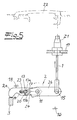
- FIG. 5 In the context of the embodiment of FIG. 5 is a Bowden cable 1, 21 from Bowden cable core 1 and Bowden cable 21 to one in a mounting point 15 connected Actuating lever 2 about its axis of rotation 11 in the counterclockwise direction to pivot.
- the operating lever 2 changes the clearance compensation of Bowden cable 1, 21 its contour, as can be seen with reference to FIG. 6 recognizes. That is, the operating lever 2 ensures that any elongations of the Bowden cable core 1 in operation be compensated automatically.
- the Operating lever 2 for the distance A between the Attachment point 15 for the Bowden cable core 1 and a Stop 19 for the Bowden cable 21 as clearance compensation is enlarged.
- the actuating lever is the second in two parts with lock arm 2a and bottom pull arm 2b.
- both arms 2a, 2b change in the course of the following to be described play compensation the between enclosed angle ⁇ .
- Both are Arms 2a, 2b pivotally connected to each other, namely about the axis or axis of rotation 11 for the actuating lever 2. This axis of rotation 11 is locked or fixed to the housing appropriate.
- the Bowdenzugarm 2b has a nose 20, which with a counter-element 13 on the lock arm 2a cooperates.
- the Counter element 13 is within the scope of the embodiment constructed in two parts and consists of a ball 13a and a merely indicated and optional and connected Guide tip 13b together.
- Ball 13a and leadership tip 13b can be in the longitudinal direction of the lock arm 2a move in a recess 23 and are of a spring 14 in the direction of the nose 20 on Bowdenzugarm 2b applied.
- the nose 20 provides in conjunction with the counter element 13 for the power transmission from the Bowden cable 1, 21 on the main operating lever 3. This is indicated by a force arrow F in the Fig. 6 indicated.
- the guide tip 13b and consequently the Position of the ball 13a and the counter-element 13 in the Guide 23 in the lock arm 2a is of a guide contour 24 given on Bowdenzugarm 2b.
- the working position 6 shows that the guide tip 13b or the counter element 13 by the force of the spring 14 on the contiguous contour 24 is applied, the one with decreasing Angle ⁇ has inwardly curved area. ever according to angular position of the arms 2a, 2b changed to one another the relevant guide contour 24 on the leadership tip 13b the position of the counter element 13a.
- two stops 16, 18 ensure that first of all a minimum angle ⁇ min between the two arms 2a, 2b is not undershot. This ensures the stop 16.
- the stopper 18 ensures that the lock arm 2a as a whole can not escape and in particular a change from the standby position shown in FIG. 5 in the working position of FIG. 6 is possible.
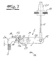
- the operating lever 2 changes in another embodiment for clearance compensation of the Bowden cable 1, 21 its contour, as can be seen with reference to FIG. 8.
- the operating lever 2 ensures that any elongations the Bowden cable core 1 automatically compensated during operation become.
- the operating lever 2 ensures that the distance A between the attachment point 15 for the Bowden cable core 1 and a stop 19 for the cable housing 21 is increased as clearance compensation.
- both arms are changing 2a, 2b in the course of the later to be described Compensate the trapped angle between them ⁇ .
- both arms 2a, 2b are pivotally connected to each other connected, via the axis or axis of rotation 11 for the actuating lever 2. This axis of rotation 11 is locked or fixed to the housing.
- the Bowdenzugarm 2b has a nose 20, which with a counter-element 13 on the lock arm 2a cooperates.
- the Counter element 13 is within the scope of the embodiment constructed in one piece and consists of a ball 13a. These Ball 13a can be in the longitudinal direction of the lock arm 2a move in a recess 23 and is by a spring 14 in the direction of the nose 20 on Bowdenzugarm 2b applied.
- the nose 20 provides in conjunction with the counter element 13 for the power transmission from the Bowden cable 1, 21 on the main operating lever 3.
- the position of the ball 13a and the Counter element 13 in the guide 23 in the lock arm 2a is from a discrete guide contour 24 in the form of a step contour specified on Bowdenzugarm 2b.
- Fig. 8 it can be seen that the counter element 13th by the force of the spring 14 at the respective contour 24th is applied.
- the relevant guide contour 24 on the Step contour the position of the counter element 13a.
- two stops 16, 18 ensure that First of all, a minimal angle between the two Armen 2a, 2b is not fallen below. That represents the Stop 16 safely.
- the stop 18 ensures that the lock arm 2a can not escape altogether and in particular a change from the ready position to Fig. 7 in the working position of FIG. 8 is possible.
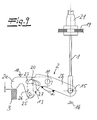
- FIG. 9 changed the operating lever 2 for clearance compensation of the Bowden cable 1, 21 its contour.
- the actuating lever is the second two-piece with lock arm 2a and Bowdenzugarm 2b executed.
- both arms 2a, 2b change in the course of the following to be described play compensation the between enclosed angle ⁇ .
- Both are Arms 2a, 2b pivotally connected to each other, namely about the axis or axis of rotation 11 for the actuating lever 2. This axis of rotation 11 is locked or fixed to the housing appropriate.
- the Bowdenzugarm 2b has a nose 20, which with a counter-element 13 on the lock arm 2a cooperates.
- the Counter element 13 is in the context of the embodiment as a rotatable about a pivot point 25 on the lock arm 2a fastened guide lever 26 with a guide element 27th built and can be in the direction of the castle arm 2a in a recess 23 and will not move from one illustrated spring in the direction of the nose 20 am Bowden cable 2b applied.
- the nose 20 provides in conjunction with the counter element 13 for the power transmission from the Bowden cable 1, 21 on the Actuator main lever 3.
- the position of the counter element 13th in the guide 23 in the lock arm 2a is from a Guiding contour 24 on Bowdenzugarm 2b given.
- the counter element 13 by the force of the spring on the concerned Contour 24 abuts the one with a decreasing angle ⁇ has inwardly curved area.
- the arms 2a, 2b to each other changes the relevant Guide contour 24, the position of the counter element 13a.
- stops 16, 18 ensure that First of all, a minimal angle between the two Armen 2a, 2b is not fallen below. That represents the Stop 16 safely. In contrast, the stop 18 ensures that the lock arm 2a as a whole can not escape.
Landscapes
- Engineering & Computer Science (AREA)
- General Engineering & Computer Science (AREA)
- Health & Medical Sciences (AREA)
- Oral & Maxillofacial Surgery (AREA)
- Mechanical Engineering (AREA)
- Lock And Its Accessories (AREA)
Abstract
Description
- Fig. 1 und 2
- perspektivische Ansichten des kombinierten Bowdenzug-/Hebelaggregates in Verbindung mit einem Kraftfahrzeugtürverschluss,
- Fig. 3 und 4
- den Gegenstand nach den Fig. 1 und 2 in schematischer Seitenansicht und zum Teil abgewandelter Ausführungsform,
- Fig. 5
- einen Teil des kombinierten Bowdenzug/Hebelaggregates in schematischer vereinfachter Darstellung im Anlieferungszustand,
- Fig. 6
- den Gegenstand nach Fig. 5 im Betrieb bzw. im Arbeitszustand mit automatisch arbeitendem Spielausgleich,
- Fig. 7
- eine zweite Ausführungsform eines Teils des kombinierten Bowdenzug-/Hebelaggregates in schematischer vereinfachter Darstellung im Anlieferungszustand,
- Fig. 8
- den Gegenstand nach Fig. 7 im Betrieb bzw. im Arbeitszustand mit automatisch arbeitendem Spielausleich und
- Fig. 9
- eine dritte Ausführungsform eines Teils des kombinierten Bowdenzug-/Hebelaggregates in schematischer vereinfachter Darstellung im Anlieferungszustand.
Claims (13)
- Kombiniertes Bowdenzug-/Hebelaggregat für insbesondere Kraftfahrzeugtürverschlüsse, mit einem Bowdenzug (1, 21) sowie einer daran angeschlossenen Betätigungselementekette (2, 3, 4, 5) mit erstem Betätigungselement (2), zweiten Betätigungselement (3) und drittem Betätigungselement (4), wobei die Betätigungselementekette (2, 3, 4, 5) drei oder mehr durch einen Arbeitshub des Bowdenzuges (1) bis zur Beaufschlagung eines Auslöse-/Sperrelementes (6, 7) zu überbrückende Spalte (S1, S2, S3) aufweist, dadurch gekennzeichnet, dass das dritte Betätigungselement (4) im Wesentlichen spielfrei auf das Auslöse/Sperrelement (6, 7) arbeitet, so dass mittels des ersten Betätigungselementes (2) das noch verbleibende Spiel in der Betätigungselementekette (2, 3, 4, 5) eingestellt wird.
- Bowdenzug-/Hebelaggregat nach Anspruch 1, dadurch gekennzeichnet, dass das dritte Betätigungselement (4) eine endseitige Ummantelung (9), insbesondere Kunststoffummantelung (9), zwischen dem betreffenden Betätigungselement (4) und dem Auslöse-/Sperrelement (6, 7) aufweist.
- Bowdenzug-/Hebelaggregat nach Anspruch 1 oder 2, dadurch gekennzeichnet, dass dritte Betätigungselement (4) endseitig einerseits an einem gehäusefesten Anschlag (10) und andererseits an dem Auslöse-/Sperrelement (6, 7) anliegt.
- Bowdenzug-/Hebelaggregat nach einem der Ansprüche 1 bis 3, dadurch gekennzeichnet, dass wenigstens ein Betätigungselement (2) der Betätigungselementekette (2, 3, 4, 5) zum Spielausgleich für den Bowdenzug (1, 21) nach einer Grundeinstellung seine Kontur verändert.
- Bowdenzug-/Hebelaggregat nach Anspruch 4, dadurch gekennzeichnet, dass das betreffende Betätigungselement (2) zweiteilig mit Schlossarm (2a) und Bowdenzugarm (2b) ausgebildet ist, wobei beide Arme (2a, 2b) drehgelenkig über eine Drehachse (11) miteinander verbunden sind.
- Bowdenzug-/Hebelaggregat nach Anspruch 4 und 5, dadurch gekennzeichnet, dass das Betätigungselement (2) seine Kontur in der Weise verändert, dass der Abstand (A) zwischen dem Befestigungspunkt (15) für die Bowdenzugseele (1) und einem Anschlag (19) für die Bowdenzughülle (2) als Spielausgleich variiert wird.
- Bowdenzug-/Hebelaggregat nach einem der Ansprüche 4 bis 6, dadurch gekennzeichnet, dass der Bowdenzugarm (4) eine Nase (20) aufweist, welche in Verbindung mit einem je nach Winkelstellung (α) der Arme (2a, 2b) zueinander verstellbarem Gegenelement (13) für die Kraftübertragung vom Bowdenzug (1, 2) auf das Betätigungselement 3 oder einen vergleichbaren Ausgangsmechanismus sorgt.
- Bowdenzug-/Hebelaggregat nach einem der Ansprüche 4 bis 7, dadurch gekennzeichnet, dass das Gegenelement (13) als im Schlossarm (2a) verschiebbar gelagerte Kugel (13a) mit gegebenenfalls angeschlossener Führungsspitze (13b), ausgeführt ist.
- Bowdenzug-/Hebelaggregat nach einem der Ansprüche 4 bis 7, dadurch gekennzeichnet, dass das Gegenelement (13) im Schlossarm (2a) drehbarer Führungshebel (26) ausgeführt ist.
- Bowdenzug-/Hebelaggregat nach einem der Ansprüche 4 bis 9, dadurch gekennzeichnet, dass das Gegenelement (13) am Schlossarm (2a) mit einer Führungskontur (24) am Bowdenzugarm (2b) zusammenwirkt.
- Bowdenzug-/Hebelaggregat nach einem der Ansprüche 4 bis 10, dadurch gekennzeichnet, dass je nach Winkelstellung (α) der Arme (2a, 2b) zueinander die Führungskontur (24) die Position des Gegenelementes (13) verändert.
- Bowdenzug-/Hebelaggregat nach einem der Ansprüche 4 bis 11, dadurch gekennzeichnet, dass mehrere Anschläge (16, 18) für den Betätigungshebel (2) vorgesehen sind.
- Bowdenzug-/Hebelaggregat nach einem der Ansprüche 4 bis 12, dadurch gekennzeichnet, dass der Betätigungshebel (4) im Anlieferungszustand (Fig. 5) ohne Spielausgleich arbeitet und erst im Arbeitszustand (Fig. 6) den automatischen Spielausgleich vornimmt.
Applications Claiming Priority (4)
| Application Number | Priority Date | Filing Date | Title |
|---|---|---|---|
| DE10331712 | 2003-07-11 | ||
| DE2003131712 DE10331712A1 (de) | 2003-07-11 | 2003-07-11 | Kombiniertes Bowdenzug-Hebelaggregat |
| DE10337392 | 2003-08-13 | ||
| DE2003137392 DE10337392A1 (de) | 2003-08-13 | 2003-08-13 | Kombiniertes Bowdenzug-/Hebelaggregat |
Publications (2)
| Publication Number | Publication Date |
|---|---|
| EP1496176A1 true EP1496176A1 (de) | 2005-01-12 |
| EP1496176B1 EP1496176B1 (de) | 2006-09-13 |
Family
ID=33453892
Family Applications (1)
| Application Number | Title | Priority Date | Filing Date |
|---|---|---|---|
| EP04015945A Expired - Lifetime EP1496176B1 (de) | 2003-07-11 | 2004-07-07 | Kombiniertes Bowdenzug-/Hebelaggregat |
Country Status (2)
| Country | Link |
|---|---|
| EP (1) | EP1496176B1 (de) |
| DE (1) | DE502004001451D1 (de) |
Citations (5)
| Publication number | Priority date | Publication date | Assignee | Title |
|---|---|---|---|---|
| FR1240022A (fr) * | 1959-07-21 | 1960-09-02 | Dispositif de sécurité pour la fermeture des portières de véhicules automobiles | |
| DE19620496A1 (de) * | 1996-05-21 | 1997-11-27 | Kuester & Co Gmbh | Vorrichtung zur Längenkorrektur oder -einstellung von Seilzügen, Betätigungszügen o. dgl. |
| DE10002215C1 (de) * | 2000-01-20 | 2001-10-04 | Huf Huelsbeck & Fuerst Gmbh | Fahrzeugtürgriff, ausgestattet mit einer Vorrichtung zur automatischen Längeneinstellung eines Seilzuges |
| DE10100636A1 (de) * | 2001-01-09 | 2002-07-18 | Huf Huelsbeck & Fuerst Gmbh | Vorrichtung zur Betätigung eines Verschlusses bei einer Tür oder einer Klappe, insbesondere bei Fahrzeugen |
| DE10300640A1 (de) * | 2002-01-26 | 2003-08-07 | Kirchhoff Gmbh & Co Kg | Vorrichtung zur Sicherung einer Haube eines Kraftfahrzeuges |
-
2004
- 2004-07-07 EP EP04015945A patent/EP1496176B1/de not_active Expired - Lifetime
- 2004-07-07 DE DE502004001451T patent/DE502004001451D1/de not_active Expired - Lifetime
Patent Citations (5)
| Publication number | Priority date | Publication date | Assignee | Title |
|---|---|---|---|---|
| FR1240022A (fr) * | 1959-07-21 | 1960-09-02 | Dispositif de sécurité pour la fermeture des portières de véhicules automobiles | |
| DE19620496A1 (de) * | 1996-05-21 | 1997-11-27 | Kuester & Co Gmbh | Vorrichtung zur Längenkorrektur oder -einstellung von Seilzügen, Betätigungszügen o. dgl. |
| DE10002215C1 (de) * | 2000-01-20 | 2001-10-04 | Huf Huelsbeck & Fuerst Gmbh | Fahrzeugtürgriff, ausgestattet mit einer Vorrichtung zur automatischen Längeneinstellung eines Seilzuges |
| DE10100636A1 (de) * | 2001-01-09 | 2002-07-18 | Huf Huelsbeck & Fuerst Gmbh | Vorrichtung zur Betätigung eines Verschlusses bei einer Tür oder einer Klappe, insbesondere bei Fahrzeugen |
| DE10300640A1 (de) * | 2002-01-26 | 2003-08-07 | Kirchhoff Gmbh & Co Kg | Vorrichtung zur Sicherung einer Haube eines Kraftfahrzeuges |
Also Published As
| Publication number | Publication date |
|---|---|
| DE502004001451D1 (de) | 2006-10-26 |
| EP1496176B1 (de) | 2006-09-13 |
Similar Documents
| Publication | Publication Date | Title |
|---|---|---|
| EP2326781B1 (de) | Schlosseinheit mit mehrteiliger sperrklinke und federvorgespannter blockierklinke | |
| DE69922373T2 (de) | Verschlussvorrichtung und haubenschloss für ein fahrzeug mit einer derartigen verschlussvorrichtung | |
| EP2893108A2 (de) | Kraftfahrzeugtürschloss | |
| EP1884611A2 (de) | Kraftfahrzeugschloß | |
| WO2008145373A1 (de) | Kraftfahrzeugtüranordnung | |
| EP3027828A1 (de) | Kraftfahrzeugtür | |
| EP3498941A1 (de) | Betätigungshandhabe mit sperrvorrichtung | |
| EP3784855B1 (de) | Kraftfahrzeugschloss | |
| DE102017216920A1 (de) | Türgriffeinrichtung für eine Tür eines Kraftfahrzeugs, Tür, Kraftfahrzeug | |
| DE2916242A1 (de) | Sicherheitsanordnung fuer tueren, fenster o.dgl. | |
| WO2017059836A1 (de) | Kraftfahrzeugtürschloss mit bewegungsdämpfer | |
| DE102012107145A1 (de) | Kraftfahrzeugtürverschluss | |
| DE102005035898A1 (de) | Drehfallenverschluss mit einer Drehfalle | |
| WO2020099961A1 (de) | Kraftfahrzeugschloss | |
| DE10339542B4 (de) | Kraftfahrzeugtürverschluss | |
| DE10337392A1 (de) | Kombiniertes Bowdenzug-/Hebelaggregat | |
| DE10013697A1 (de) | Feststellvorrichtung | |
| EP1496176B1 (de) | Kombiniertes Bowdenzug-/Hebelaggregat | |
| DE202006011218U1 (de) | Notfallentriegelung | |
| DE10151870A1 (de) | Vorrichtung zur Betätigung eines Verschlusses von Türen oder Klappen, insbesondere an Fahrzeugen | |
| DE102017119252A1 (de) | Funktionskomponente einer Kraftfahrzeugschlossanordnung | |
| DE102007012684A1 (de) | Betätigungsvorrichtung zur Betätigung einer Schlossbaugruppe eines Kraftfahrzeugs | |
| EP2006176B1 (de) | Feststellbremseinrichtung | |
| DE4339654A1 (de) | Kraftfahrzeugtürverschluß | |
| EP3192952B1 (de) | Kraftfahrzeugschloss |
Legal Events
| Date | Code | Title | Description |
|---|---|---|---|
| PUAI | Public reference made under article 153(3) epc to a published international application that has entered the european phase |
Free format text: ORIGINAL CODE: 0009012 |
|
| AK | Designated contracting states |
Kind code of ref document: A1 Designated state(s): AT BE BG CH CY CZ DE DK EE ES FI FR GB GR HU IE IT LI LU MC NL PL PT RO SE SI SK TR |
|
| AX | Request for extension of the european patent |
Extension state: AL HR LT LV MK |
|
| 17P | Request for examination filed |
Effective date: 20050623 |
|
| AKX | Designation fees paid |
Designated state(s): DE FR |
|
| GRAP | Despatch of communication of intention to grant a patent |
Free format text: ORIGINAL CODE: EPIDOSNIGR1 |
|
| GRAS | Grant fee paid |
Free format text: ORIGINAL CODE: EPIDOSNIGR3 |
|
| GRAA | (expected) grant |
Free format text: ORIGINAL CODE: 0009210 |
|
| AK | Designated contracting states |
Kind code of ref document: B1 Designated state(s): DE FR |
|
| REF | Corresponds to: |
Ref document number: 502004001451 Country of ref document: DE Date of ref document: 20061026 Kind code of ref document: P |
|
| ET | Fr: translation filed | ||
| PLBE | No opposition filed within time limit |
Free format text: ORIGINAL CODE: 0009261 |
|
| STAA | Information on the status of an ep patent application or granted ep patent |
Free format text: STATUS: NO OPPOSITION FILED WITHIN TIME LIMIT |
|
| 26N | No opposition filed |
Effective date: 20070614 |
|
| PGFP | Annual fee paid to national office [announced via postgrant information from national office to epo] |
Ref country code: FR Payment date: 20100802 Year of fee payment: 7 |
|
| REG | Reference to a national code |
Ref country code: FR Ref legal event code: ST Effective date: 20120330 |
|
| PG25 | Lapsed in a contracting state [announced via postgrant information from national office to epo] |
Ref country code: FR Free format text: LAPSE BECAUSE OF NON-PAYMENT OF DUE FEES Effective date: 20110801 |
|
| P01 | Opt-out of the competence of the unified patent court (upc) registered |
Effective date: 20230529 |
|
| PGFP | Annual fee paid to national office [announced via postgrant information from national office to epo] |
Ref country code: DE Payment date: 20230720 Year of fee payment: 20 |
|
| REG | Reference to a national code |
Ref country code: DE Ref legal event code: R071 Ref document number: 502004001451 Country of ref document: DE |