EP1495716B1 - Verarbeitung von Elektrokardiogrammsignälen mit überlappenden Komplexen - Google Patents
Verarbeitung von Elektrokardiogrammsignälen mit überlappenden Komplexen Download PDFInfo
- Publication number
- EP1495716B1 EP1495716B1 EP04016344A EP04016344A EP1495716B1 EP 1495716 B1 EP1495716 B1 EP 1495716B1 EP 04016344 A EP04016344 A EP 04016344A EP 04016344 A EP04016344 A EP 04016344A EP 1495716 B1 EP1495716 B1 EP 1495716B1
- Authority
- EP
- European Patent Office
- Prior art keywords
- signal
- template
- paced
- signals
- wave
- Prior art date
- Legal status (The legal status is an assumption and is not a legal conclusion. Google has not performed a legal analysis and makes no representation as to the accuracy of the status listed.)
- Expired - Lifetime
Links
Images


Classifications
-
- A—HUMAN NECESSITIES
- A61—MEDICAL OR VETERINARY SCIENCE; HYGIENE
- A61B—DIAGNOSIS; SURGERY; IDENTIFICATION
- A61B5/00—Measuring for diagnostic purposes; Identification of persons
- A61B5/24—Detecting, measuring or recording bioelectric or biomagnetic signals of the body or parts thereof
- A61B5/316—Modalities, i.e. specific diagnostic methods
- A61B5/318—Heart-related electrical modalities, e.g. electrocardiography [ECG]
- A61B5/346—Analysis of electrocardiograms
- A61B5/349—Detecting specific parameters of the electrocardiograph cycle
- A61B5/35—Detecting specific parameters of the electrocardiograph cycle by template matching
-
- A—HUMAN NECESSITIES
- A61—MEDICAL OR VETERINARY SCIENCE; HYGIENE
- A61B—DIAGNOSIS; SURGERY; IDENTIFICATION
- A61B5/00—Measuring for diagnostic purposes; Identification of persons
- A61B5/24—Detecting, measuring or recording bioelectric or biomagnetic signals of the body or parts thereof
- A61B5/316—Modalities, i.e. specific diagnostic methods
- A61B5/318—Heart-related electrical modalities, e.g. electrocardiography [ECG]
- A61B5/346—Analysis of electrocardiograms
- A61B5/349—Detecting specific parameters of the electrocardiograph cycle
- A61B5/364—Detecting abnormal ECG interval, e.g. extrasystoles, ectopic heartbeats
-
- A—HUMAN NECESSITIES
- A61—MEDICAL OR VETERINARY SCIENCE; HYGIENE
- A61B—DIAGNOSIS; SURGERY; IDENTIFICATION
- A61B5/00—Measuring for diagnostic purposes; Identification of persons
- A61B5/74—Details of notification to user or communication with user or patient; User input means
- A61B5/742—Details of notification to user or communication with user or patient; User input means using visual displays
- A61B5/7445—Display arrangements, e.g. multiple display units
-
- A—HUMAN NECESSITIES
- A61—MEDICAL OR VETERINARY SCIENCE; HYGIENE
- A61B—DIAGNOSIS; SURGERY; IDENTIFICATION
- A61B5/00—Measuring for diagnostic purposes; Identification of persons
- A61B5/24—Detecting, measuring or recording bioelectric or biomagnetic signals of the body or parts thereof
- A61B5/316—Modalities, i.e. specific diagnostic methods
- A61B5/318—Heart-related electrical modalities, e.g. electrocardiography [ECG]
- A61B5/346—Analysis of electrocardiograms
- A61B5/349—Detecting specific parameters of the electrocardiograph cycle
- A61B5/363—Detecting tachycardia or bradycardia
Definitions
- This invention relates to a method for processing electrical signals obtained from the heart and, more particularly, to a method for processing electrocardiac signals having superimposed sub-component complexes to enable tracking of native, paced, and derived beat signals.
- Certain cardiac arrhythmias are triggered or initiated from a site in the heart tissue other than the sinus node. These arrhythmias are generally classified as being "focal” in nature. Treatment of focal arrhythmias generally involves locating the arrhythmogenic site and ablating it.
- One method for regionally locating the focal site is the use of a diagnostic 12 Lead ECG.
- the 12 Lead can be used in conjunction with pacing via a roving intracardiac catheter to pace map the heart.
- the theoretical basis of this method assumes that the paced 12 lead ECG will appear identical to the non-paced ECG if the cycle length (i.e., paced heart rate) and pacing site matches the non-paced heart rate and focal site of origin.
- a second problem is the time consuming nature of the procedure in which, typically, a spontaneous ectopic beat is recorded and printed on paper.
- a roving mapping catheter is positioned at a likely site of ectopy, pacing is initiated, a recording is made, a printout is generated and a visual comparison is made by aligning the printouts from the spontaneous and paced beats over one another. This process is repeated in an iterative manner until the physician determines that a good match between the spontaneous ectopic beat and the paced beat is found.
- a fourth problem involves the superimposition of the P-wave and T-wave components of the ECG.
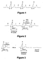
- the electrocardiogram typically includes an initial impulse, termed the P-wave, emanating from the atria, followed by what is termed the QRS complex, emanating from the ventricles, which is followed by a T-wave resulting from repolarization of the ventricles ( Fig. 1 ).
- P-wave initial impulse
- QRS complex QRS complex
- the P-wave can be a valuable tool used by clinicians to diagnose the condition of the heart.
- clinicians will often monitor an electrocardiogram (ECG) of the heart to aid in the diagnosis of atrial and ventricular arrhythmias.
- ECG electrocardiogram
- This can be done in various ways, such as by monitoring the 12 Lead (surface) ECG in conjunction with observing the bioelectric activity recorded on intracardiac electrodes carried by a transthoracic catheter.
- the atrial heart tissue begins to beat very rapidly as the focal origin moves from the sinus node to an ectopic site.
- this higher heart rate is sustained over three or more beats and is termed a tachycardia.
- the higher rate is intermittent and may be as short as one heart beat.
- the first beat of the atrial arrhythmia is usually initiated by what is termed a Premature Atrial Contraction ("PAC") which can result in the P-wave of a successive heart beat overlapping with the T-wave of the preceding beat ( Fig. 2 ).
- PAC Premature Atrial Contraction
- US 5,311,873 discloses a pace mapping method where reference heart beat data and paced heart beat data are used to produce a correlation coefficient.
- the pre-amble of claim 1 is based on this document.
- T-wave subtraction is a useful method in electrophysiology procedures to unmask the ECG P-wave morphology of a PAC by subtracting a QRS-T template from a PAC
- ECG baseline drift caused by respiration or body movement may cause certain variations on the results of T-wave subtraction.
- a further need remains in the art to quantitatively measure the quality of T-wave subtraction results, among other reasons to monitor the respiration variations on T-wave subtraction. The instant disclosure addresses this need as well.
- the present invention provides a system as defined in claim 1.
- the present disclosure provides, a medical practitioner with a computerized method for objectively and efficiently performing real time pace mapping and other cardiac analyses, through the processing of incoming electrical signals which represent heart activity to display a derived P-wave without any overlap with a preceding T-wave during a PAC, and to allow the practitioner to objectively compare derived P-waves to determine if they are emanating from the same focus.
- cardiac signal processing of the present invention otherwise masked signals and correlations are identified among heart beats and segments of heart beats through calculations on acquired signals and/or derivations of new signals.
- the practitioner can be guided through visual aids such as bar graphs and overlaid cardiac signals of the quality of signal matches. These signal matches can assist in diagnosing a patient and in the effectiveness of an ongoing treatment, for example, an ablation procedure.
- Sub-component waveforms can be quantitatively compared to one another using correlation analysis. This analysis may be done retrospectively or in real time.
- the present disclosure provides systems, programmed machines, and methods that permit superior signal processing over prior art electrophysiology signal processors and can achieve this using a standard 12 lead ECG..
- a system for tracking ectopic beats comprises a signal sensing unit, a signal processor, and an output device.
- the signal sensing unit is configured to capture a first ECG signal.
- the signal processor is connected to receive the first ECG signal from the signal sensing unit and is configured to permit a user to mark a begin point and an end point of the first ECG signal for use in defining a waveform segment as a reference template, to acquire data from multiple leads, and to identify a best fit between the reference template and the acquired data using a correlation coefficient calculation.
- the output device presents the identified best fit.
- a system for deriving a p-wave signal from a premature atrial contraction (“PAC") beat comprises a signal sensing unit, a signal processor, and an output device.
- the signal processor is connected so as to receive electrocardiac signals from the signal sensing unit and is configured to process the electrocardiac signals so as to derive the P-wave signal from the PAC beat.
- the output device presents the derived P-wave signal.
- the processor is configured to execute the steps of: (a) selecting a QRS-T segment of a reference ECG signal; (b) permitting a user to mark a begin point and an end point of the selected ECG signal; (c) defining a reference template as being a waveform segment between the marked begin and end points of the selected ECG signal; (d) acquiring the PAC beat at the signal processing unit from multiple leads (preferably with no more than 12 leads); and (e) processing the PAC beat so as to derive the P-wave signal.
- an electrophysiology computer system includes a processor that is configured to derive a P-wave signal hidden within a premature atrial contraction ("PAC") beat.
- the processor executes the steps of: (a) selecting a QRS-T segment of a reference ECG signal; (b) permitting a user to mark a begin point and an end point of the selected segment of the reference ECG signal; (c) defining a reference template as being a waveform segment between the marked begin and end points of the selected segment of the reference ECG signal; (d) acquiring the PAC beat at the signal processing unit from multiple ECG leads; and (e) processing the PAC beat so as to derive the p-wave signal.
- PAC premature atrial contraction
- the processor utilizes a correlation coefficient calculation to effect a subtraction of the reference template from a predetermined segment of the PAC beat.
- the processor is configured to compare derived P-waves from multiple beats to one another, to indicate or infer a common focal origin among several derived P-waves, to predict the most likely site of the origin of a focus using a (preferably 12 lead) library of p-waves of known focal origin, to derive paced P-waves for comparison to spontaneous p-waves, to determine an integral value of the QRS area of a derived P-wave signal, to normalize any integral values over a length of the derived P-wave signal, to process the QRS segment of a beat separately to arrive at further determinations concerning the heart beat data, and to perform combinations of the foregoing.
- an electrophysiology computer system includes a processor that is configured to execute steps substantially in the same manner as the processor that derives a P-wave from a PAC beat, but more generally is configured to derive a non-synchronous subcomponent from a first heartbeat signal having a composite waveform which includes a synchronous subcomponent overlapping the non-synchronous subcomponent.
- the processor executes the steps of selecting a synchronous subcomponent of a second heartbeat signal which corresponds to the synchronous subcomponent of the first heartbeat signal; permitting a user to mark a begin point and an end point of the selected synchronous subcomponent; defining a reference template as being a waveform segment between the marked begin and end points of the selected synchronous subcomponent; acquiring the composite waveform of the first heartbeat signal at the signal processing unit from multiple leads; and processing the composite waveform beat so as to derive the non-synchronous subcomponent.
- a method for tracking ectopic beats through template matching includes the steps of: (a) capturing a first ECG signal in a signal processing unit; (b) permitting a user to mark a begin point and an end point of the captured first ECG signal; (c) defining a reference template as being a waveform segment between the marked begin and end points of the first ECG signal; (d) acquiring data at the signal processing unit; and (e) using a correlation coefficient calculation on the acquired data to identify a best fit between the reference template and the acquired data.
- a method for deriving a P-wave signal from a premature atrial contraction ("PAC") beat which can assist a person in diagnosing a heart.
- This method includes the steps of: (a)selecting a QRS-T segment of a reference ECG signal; (b) permitting a user to mark a begin point and an end point of the selected segment of the reference ECG signal; (c) defining a reference template as being a waveform segment between the marked begin and end points of the selected segment of the reference ECG signal; (d) acquiring the PAC beat at the signal processing unit from multiple leads; and (e) processing the PAC beat so as to derive the p-wave signal.
- PAC premature atrial contraction
- the PAC beat is processed using a correlation coefficient calculation to effect a subtraction of the reference template from a predetermined segment of the PAC beat.
- the foregoing methods can include the additional steps of: comparing derived p-waves from multiple beats to one another; indicating or inferring a common focal origin among several derived p-waves; predicting the most likely site of the origin of a focus using a (preferably 12 lead) library of P-waves of known focal origin; deriving paced P-waves for comparison to spontaneous P-waves; determining an integral value of the QRS area of a derived P-wave signal; normalizing any integral values over a length of the derived p-wave signal; processing QRS segment of a beat separately to arrive at further determinations concerning the heart beat data, and performing combinations of the foregoing steps.
- Further methods according to still further aspects of the disclosure include the determination of integrals concerning a section of the QRS-T segment and the processing of those integrals.
- a QRS segment integral can be used as a measure of the QRS residue, which is an indicator of the alignment or synchronization quality between the template QRS and the PAC QRS
- baseline drift can be monitored as a change of the QRS absolute peak (integral) value percentage between the template and the PAC.
- Yet a further method in accordance with another aspect of the disclosure proceeds in substantially the same manner as when deriving a p-wave from a PAC beat, but more generally includes the selecting the synchronous subcomponent of the heartbeat signal, permitting a user to mark a begin point and an end point of the selected synchronous subcomponent, defining a reference template as being a waveform segment between the marked begin and end points of the selected synchronous subcomponent, acquiring the composite waveform at the signal processing unit from multiple leads, and processing the composite waveform beat so as to derive the non-synchronous subcomponent.
- a compare display method for displaying sequential paced signal/template matches that decreases the time required to perform a pace-mapping procedure.
- the compare display method includes the steps of simultaneously displaying a template, a most recent paced signal/template match, and a second-most recent paced signal/template match.
- the compare display method includes the steps of simultaneously displaying a template, a most recent paced signal/template match, and a previous paced signal/template best match.
- a template optimization method which dynamically employs different templates. QRS beats that precede or follow a PAC can be selected manually or by action of a programmed machine in selecting and setting a new template for use in subsequent calculations.
- the method is implemented by suitably configured computer processors.
- Any recorded ECG waveform can be used as a reference to compare to another recorded ECG waveform or to a real time ECG waveform.
- the comparison is performed in a two step process in which first a reference template is selected by the user to describe the beginning and end of an ECG waveform segment to be used as a comparison template. Next the user selects the region of data to be used for comparison--either from pre-recorded data or from the real time data stream.
- a suitably configured computer processor can find the best match against the reference template over the region specified, or in the case of real time analysis, find the best match updated over a defined period of time, for example every second.
- the criteria for "best match" utilizes a correlation coefficient calculation across all twelve leads of the ECG and finds the best alignment.
- This calculation may be preceded by a correlation assessment that is taken across fewer leads, such as only one lead, to generally align the reference template to the selected region of data that is of interest.
- a visual display showing the aligned reference beat (template) overlaid on the beat undergoing analysis give the user feedback as to the closeness of the match.
- a correlation coefficient calculated for each ECG lead gives a quantitative indicator of the match.
- a composite average is also calculated and is displayed in a unique color enhanced bar graph indicator which is especially useful when real time template matching is being performed. The composite average can be updated as a moving average over a preselected number of beats.
- Template matching may be used to compare two spontaneous beats or it can be used to pace map, i.e., to compare a paced beat to a spontaneous beat.
- a Region of Interest (ROI) indictor can be manipulated by the user to exclude certain portions of the waveform from analysis. This is useful during pace mapping where pacing artifacts on the surface leads can be excluded from the region of analysis.
- the ROI indicator can also be used to specify a preference for T-wave or P-wave matching as they are oftentimes morphologically very similar.
- a method whereby an ECG having an overlapping P and T wave is processed to remove the T-wave and thereby display the P-wave without any overlap, so that a clinician may observe the P-wave when performing a diagnosis of the heart.
- FIG. 1 which describes a normal ECG over three beats in which distinctive P and T-waves can be identified.
- Figure 2 shows a rhythm in which the P- wave from the third beat (P') arrives early and is obscured by the T-wave from the second beat. This results in what is termed a P on T complex, and is referred to as a QRS-T-P' in the figure.
- the QRS-T segment of a beat that lacks a PAC is selected as a template.
- This template is subtracted from the QRS-T-P' signal in the PAC to be studied yielding the P-wave.
- the QRS-T signal used as the template may be from a single beat or it may be derived from an average of multiple beats.
- the QRS-T signal (or average) used as the template is selected so that the preceding QRS-QRS interval is equal (or nearly equal) to the QRS-QRS interval immediately preceding the QRS-T-P' signal to be studied.
- the beat immediately preceding the PAC can be used for the selected QRS-T template as the cycle length and hemodynamic conditions of this beat are the closest to those of the succeeding beat that contains the PAC and P on T complex. (See Figures 2 and 3 .)
- the QRS complex is used as a means to synchronize and align the QRS-T template and the PAC beat for subtraction.
- the alignment is automated by the algorithm for the best match based on the composite correlation coefficient across the 12 Lead ECG.
- the practitioner has the option of shifting the template match left or right on a sample by sample basis with the resulting composite correlation coefficient updated at each new position.
- the practitioner also has the option of choosing the previous or following QRS-T segment as the reference template.
- the software will automatically locate the previous or following beat based on the current reference template and use the corresponding QRS-T segment of that beat as the new reference template in the calculation of derived P-waves.
- P-waves that have been derived using the T-wave subtraction method can be signal processed further to remove unwanted artifacts caused by respiration or noise.
- two or more waveforms X,Y, .. may form a composite waveform that due to timing and amplitude relationships causes the individual waveforms to be obscured or hidden.
- the composite waveform includes a synchronous subcomponent overlapping a non-synchronous subcomponent. If a singular, unadulterated sub-component waveform (e.g. X or Y) can be identified, and if it has similar timing characteristics that allow it to be synchronized with the composite waveform (i.e., this identified subcomponent is the synchronous subcomponent), then it can be subtracted from the composite waveform to derive the other sub-component waveform(s) (i.e., the non-synchronous subcomponent(s)).
- a singular, unadulterated sub-component waveform e.g. X or Y
- this identified subcomponent is the synchronous subcomponent
- Sub-component waveforms can be quantitatively compared to one another using correlation analysis. This analysis may be done retrospectively or in real time.
- One of skill in the art will appreciate that a number of algorithms can be used to compare waveform shape, including, but not limited to bin area methods and integrals; any of these methods can assist in the goals of aligning synchronous components of composite waveforms and/or comparing the derived results.
- a method in accordance with this more general teaching proceeds generally as outlined above. Specifically, this method proceeds in substantially the same manner as when deriving a P-wave from a PAC beat, but more generally includes the selecting the synchronous subcomponent of the heartbeat signal, permitting a user to mark a begin point and an end point of the selected synchronous subcomponent, defining a reference template as being a waveform segment between the marked begin and end points of the selected synchronous subcomponent, acquiring the composite waveform at the signal processing unit from multiple leads, and processing the composite waveform beat so as to derive the non-synchronous subcomponent.
- the system 10 includes a signal sensing unit 12, which may take different forms, such as a standard 12 lead ECG, intracardiac lead, or combination thereof.
- the signal sensing unit is electrically connected to a signal processing device 14, which receives the sensed signals from the unit 12 and processes the signals, as is described in more detail below.
- the signal processing device (“signal processor” or “processor”) 14 is preferably connected to a suitable display 16, which will present the processed signals to a clinician or other interested person. Information can be stored and recalled from a storage device 18.
- the signal processing device 14 and display 16 comprise the EP LabSystem (trademark) of C.R. Bard, Inc., Murray Hill, New Jersey, or the like.
- the EP LabSystem (trademark) supports a variety of data gathering and processing functions that are standard in electrophysiology procedures, and can have its hardware (namely, processor 14) configured to implement the subtraction and derivation methods set forth above, for example, through software (e.g., modules, procedures, functions, or objects) or firmware.
- the processor 14 communicates with a memory or storage 18 which configures the processor to implement the subtraction and derivation methods above (as well as the integral techniques described below).
- the special features of the system of the present invention are implemented, in part, by a processor using program information stored in a memory of the signal processing device 14.
- the processor 14 can access one or more files, as necessary, to implement the required functions, as described in greater detail in connection with FIG. 5 and FIG 6 .
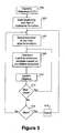
- the process begins when a clinician desires to create a reference template, and this occurs by capturing a reference ECG signal, as indicated at step 502.
- the reference ECG signal is captured using a standard 12 lead device and/or one or more intracardiac leads.
- the QRS-T signal components of a beat which does not exhibit P- on T-wave are selected as a template and it is this set of electrocardiac signal components that is captured at step 502.
- Such a beat can be captured in sinus rhythm or during a focal arrhythmia such as a tachycardia.
- the reference template results from signals captured either at the surface, from intracardiac leads that can be placed in a variety of locations within the heart, or a combination of signals from surface and intracardiac leads.
- the QRS-T signal that is used as the template can be captured from a single heartbeat or may be a signal derived from an average of multiple heart beats.
- beginning and end points of the reference template are marked by the clinician using an interface to the signal processing unit 14.
- the marked points define the segment of the ECG waveform to be used as a comparison template.
- the clinician selects whether recorded or real-time data is to be used in the template matching analysis. (This step can be performed at any time prior to the waveform matching analysis at step 508, for example, prior to performing steps 502 and 504.) If recorded data is to be used in the template matching analysis, then a specified region of pre-recorded data is provided to the signal processing unit for comparison to the reference template. On the other hand, if real-time data is to be used in the template matching analysis, a stream of data from ECG leads is provided to the signal processing unit 14 over a defined period of time for comparison to the reference template.
- the signal processor 14 finds a "best match,” in other words, a best alignment between the selected region or time period and the reference template.
- the display 16 is updated to indicate to the clinician (or other persons) the result of the template match.
- the results can be shown qualitatively as superimposed ECG waveform signals, namely, the reference beat (template) overlaid upon the beat under analysis to show the degree of alignment therebetween, or quantitatively as a correlation coefficient calculated for each ECG lead.
- a composite average is also calculated and displayed. This is illustrated in the computer display shown in FIG 8 .
- Figure 8(a) illustrates a compare display in which the second-most recent paced signal/template match (compare 1), the template, and the most recent paced signal/template match (compare 2) are simultaneously displayed.
- a test is made to determine whether the user had selected real-time processing at step 506. If so, then the flow loops back to step 508 to again perform the template matching analysis and to update the display accordingly. Otherwise, if previously recorded segments are being analyzed, the user is given the option to save the analysis (as tested at step 514), and the correlation analysis is saved, as indicated at step 516. Real-time analyses can also be saved if desired.
- the process begins at step 602 when a clinician captures a PAC and desires to subtract a QRS-T reference template from the PAC.
- the QRS-T reference template is marked by the clinician at step 604 (as described above) and a region encompassing the PAC is selected by the clinician at step 606 for analysis.
- the QRS portion of the reference template is aligned for best fit with the QRS complex immediately preceding the PAC at step 608.
- the processor 14 subtracts the QRS-T reference template from the QRS-T-P' segment of the PAC at step 610.
- the difference is the derived P-wave which is output to the display 16 at step 612.
- This is illustrated in the computer display shown in FIG 7 , in which the leftmost window displays the selected QRS-T reference template between two vertical lines (one dashed line prior to the 14 second mark at the top (highlighted by an arrow), and a second solid line just after the 14 second mark).
- the rightmost window shows the original PAC waveform with the derived P-wave overlaid on top of the portion of the ECG which occurs in the first 15 seconds.
- the overlaid and derived P-wave appears as a second graph superimposed over the ECG signals.
- Visual aids can be provided to automatically align and overlay waveforms for visual comparison on a computer display or a printout.
- Figure 8 illustrates an exemplary display for template matching (without subtraction) that can be displayed to an operator.
- the leftmost window displays markers which signify the presence and use of the reference template; the reference template beginning at the leftmost vertical line (highlighted by the arrow) and ends at the second vertical line.
- the reference template marks the start and finish of a P-wave; however, any waveform segment can be used if the region of interest has been marked for use as a template.
- the larger display window to the right shows the correlation value for each channel of the 12 Lead ECG as compared to the reference template.
- the bar graph at the far right is inactive in this example because the analysis region is taken from recorded data rather than real-time data gathered during a medical procedure.
- the data can be saved, printed or both, if desired, in response to a user input to do so, as tested at step 614 and implemented at step 616.
- the present disclosure provides a method for reliably and efficiently recovering a P-wave from a waveform that has overlapping P- and T-waves.
- the template matching capabilities of the invention provide the added benefit of quickly and objectively comparing ECG waveform components, in their native or derived state. It should also be understood that the correlation, subtraction and derivation methods described herein apply to data that can be acquired from conventional 12 lead surface ECG signals as well as intracardiac signals or combinations of both surface and intracardiac signals.
- Two waveforms can have a high correlation to each other but still be poorly matched in absolute terms due to amplitude variation and drift caused by the effects of respiration. This can be a problem when two waveforms are aligned and then subtracted, one from the other. It is for this reason that immediately adjacent beats are usually desirable as the reference (QRS-T) and PAC (QRS-T-P'). This is not always possible and is not practical when performing real time pace mapping.
- a subtraction process (as illustrated in Figs. 3 and 6 and described above) is performed to subtract a QRS-T template from a PAC (QRS-T-P') and thereby derive a waveform.
- the method of Fig. 9 proceeds by then providing integral calculations that enable a number of measurements of interest to practitioners, including, but not limited to: measures of QRS residue and the quality of the T-wave subtraction process; measures of the baseline drift, if any; and optimization of the selection of templates to be used in the subtraction process.
- the area of a derived waveform is measured.
- the integral value is divided by the length of the derived waveform to normalize its value.
- the amplitude of the normalized integral value is measured and displayed as a voltage at the ECG channel's input. This voltage value is termed the QRS residue.
- correlation analysis is used to align the QRS segment of a reference ECG template with the QRS segment of a PAC beat.
- a further improvement may use the correlation coefficient in conjunction with the so-called QRS residue of the derived waveform to give an indication of the quality if the match between two beats chosen for subtraction. Together, they provide an indicator of the alignment or synchronization quality between the template QRS and the PAC QRS.
- the derived QRS segment should be flat indicating a high correlation to the template and the QRS residue should be very small indicating a small difference in absolute amplitudes (including drift).
- Pace-mapping is used to localize the origin of an arrhythmia. Pace-mapping is a time-consuming procedure because electrocardiac signals are sequentially elicited by pacing the heart with an intracardiac electrode and then comparing the elicited signal to a spontaneous arrhythmia signal.
- the spontaneous arrhythmia signal serves as a template against which the paced signals are matched.
- a comparison is made between each paced signal and the arrhythmia signal.
- a close match between the paced signal and the arrhythmia signal is an indication that the origin of the arrhythmia has been identified.
- the user analyses each iteration to determine whether the most recent paced signal is closer to or further from the origin of the arrhythmia than the second-most recent paced signal or the previous best-matched paced signal.
- the analysis has conventionally been performed by comparing (or matching) the paced signal to the arrhythmia signal template using either (1) a print-out of the second most recent paced signal or (2) the user's memory of the second-most-recent paced signal.
- the user decides on the location at which to position the intracardiac electrode for the next paced signal based on this analysis.
- the user attempts to "walk" the pacing catheter towards the origin of the arrhythmia by sequentially moving the pacing catheter in the direction of paced signal/template matches with comparatively higher correlations and away from paced signal/template matches with comparatively lower correlations.
- the origin of the arrhythmia is eventually identified when a highly correlated match between the paced signal and the template is found.
- the compare display method of the present invention shortens the time required to perform pace-mapping by permitting the user to simultaneously view the most recent "step” in the walk (namely, the current probe location) with the just prior step in the walk (namely, the immediately preceding probe location).
- the user is not required to take the time to print the second-most recent paced signal to inform the next placement or direction for placing the probe.
- the user can simultaneously view the most recent "step” in the walk (namely, the current probe location) with the previous best step in the walk (namely, the previous probe location that produced the signal with the best template match).
- the compare display method includes displaying the template in a first panel of a three-way split screen, the most recent paced signal/template match in a second panel of a three-way split screen, and the second-most recent paced signal/template match in a third panel of a three-way split screen.
- the pace-mapping procedure of this embodiment can be used to more rapidly locate an ectopic signal due to the simultaneous display of multiple steps in the "walk."
- a roving catheter is introduced into the heart in a conventional manner.
- the roving catheter includes a pacing electrode that delivers a signal to depolarize the heart at a location of contact with the heart wall.
- One or more such electrodes can be included on the roving catheter.
- the roving catheter is brought into contact with the heart wall at a first location and a pacing pulse is delivered in a conventional manner.
- the pacing pulse causes depolarization of the heart and the cardiac waveform elicited by the pacing pulse is obtained.
- the pacing electrode of the roving catheter is then energized at a second location on the heart wall, either by energizing a different electrode while maintaining the catheter in place or by moving the catheter to a different location.
- a second paced signal is elicited at the second location in response to this second energization.
- Each of the paced signals is representative of the heart's response to a pacing pulse and comprises at least one heart signal or heart signal segment.
- a reference template as described previously is used to correlate the heart's response to the signal beat to be located. More particularly, the reference template is a waveform that represents the ectopic signal of interest and the correlation is performed to find the highest coincidence between the reference template and the paced signal.
- a high correlation (namely, a best fit between the template and the paced signal) is indicative of the roving catheter being disposed on the focus of the ectopic beat.
- a reference template 810 is shown on an electronic display 800 in a central window or frame 820.
- the reference template 810 is shown in a best-fit overlapping relationship to a first paced signal 840. Additional information can be displayed in the window or frame 830 including a quantitative indicator of the correlation coefficient that was calculated to arrive at the best fit, or a graph indicator of the degree or percentage of the match shown in that window.
- the reference template 810 is again illustrated, this time in overlapping relationship to a second paced signal 860.
- Fig. 8A shows a template constructed from only one lead signal and paced signals from only one lead.
- a trigger and an offset can be set to minimize the computational requirements of processing the template against a data signal and to quickly focus the user on the ROI, thereby resulting in a less time-consuming electrophysiology procedure.
- the trigger can be any portion of an electrocardiac signal (e.g., a Q-wave, an R-wave), a paced pulse (e.g., the last pulse of a paced stimulation train), an EP waveform event, an activation pattern, or external timing signals (e.g., a stimulator or a QRS detector that provides timing signals such as the last stimulation pulse or the start of a QRS etc.) or any combination of the foregoing.
- the trigger can be further defined as a property of the designated portion of an electrocardiac signal (e.g., threshold amplitude, peak, slope).
- an electrocardiac signal e.g., threshold amplitude, peak, slope
- the user or a program governing the signal processing functions defines the peak of an R-wave as the trigger, which results in triggering at the point in time when the R-wave has reached a peak.
- the property of an electrocardiac signal may be either a positive or negative value.
- the positive slope or the negative slope of a Q-wave may be defined as the property.
- the offset is a time delay that follows the trigger.
- the offset is typically set in the millisecond range, by the user.
- a default offset can be stored and used by the governing software.
- the template matching process is performed following each offset.
- the offset is preferably defined by the user such that the region of interest appears in the acquired data soon after the expiration of the offset. In this way, computational needs are focused on the region of interest.
- the offset can be a negative value representing a desired point in time prior to a triggering event that the operator wishes to use.
- the trigger occurs after the beginning of a ROI and the software recalls the data signal from a buffer or storage to commence template matching at a time prior to the triggering event that is equal to the offset value.
- Figure 10(a) illustrates a process in which template matching is performed without regard to a trigger or an offset.
- the entire incoming stream of data is processed for template matching and the user must observe data both within and outside of the ROI.
- Figure 10(b) illustrates the advantages of the use of a trigger and offset.
- a user plans to use the method of template matching on a stream of real-time ECG data.
- the user's template is an ectopic P-wave.
- the user selects R-wave peaks as the trigger and 200 milliseconds as the offset.
- This offset is selected, for example, on the basis of an expectation that P-waves (the ROI) will appear at a certain time following the trigger.
- Real-time data is then acquired.
- the microprocessor identifies the trigger event, delays for the time period of the offset, and then begins the template matching computations close in time to the ROI, thereby minimizing template matching processing computational effort.
- the user can focus on the template match performed in the ROI without the distraction of irrelevant comparisons performed outside of the ROI.
- the trigger is identified at the peak of the R-wave as indicated by arrow 1010. That trigger point begins the offset interval 1020, which in this example is a 200ms. During that 20ms interval, portions of the cardiac signal that precede the region of interest are not processed, such as the bounce off of the R-wave and the S-wave. Thereafter, the ROI 1030 occurs and this portion of the cardiac cycle is matched against the template, as previously described.
- the user can select a termination of the matching interval 1030.
- the termination of the matching interval 1030 can coincide with a cardiac event such as detection of a Q-wave or some other waveform segment, or with a cardiac parameter such as threshold amplitude or slope, or it can be a prescribed time after the offset, or can be a parameter relating to the correlation computation such as exceeding a correlation coefficient threshold.
- a cardiac event such as detection of a Q-wave or some other waveform segment
- a cardiac parameter such as threshold amplitude or slope
- it can be a prescribed time after the offset, or can be a parameter relating to the correlation computation such as exceeding a correlation coefficient threshold.
- a user can discern whether one or more than one arrhythmia is present. For example, two close in space, but separate and distinct, ectopic foci can emit arrhythmia signals that are morphologically similar. Determining the number of distinct arrhythmias and the location of the each arrhythmia's ectopic focus are diagnostically and therapeutically significant steps for subsequent treatment of the arrhythmias by ablation of each arrhythmia's ectopic focus. In accordance with the following methods, a user can (1) determine the number of distinct arrhythmias present and (2) locate the ectopic focus of each distinct arrhythmia using pace mapping.
- a first arrhythmia signal is acquired and defined by the user as a template (template 1).
- a second arrhythmia signal is acquired and selected for correlation to template 1.
- a correlation coefficient is calculated to find the best alignment between template 1 and the second arrhythmia signal.
- a best alignment correlation that falls below prescribed criteria indicates that the first arrhythmia signal and the second arrhythmia signal originate from different ectopic foci because the distinct ectopic foci cause distinct arrhythmic signal patterns.
- a best alignment correlation that meets or exceeds the prescribed criteria indicates that the first arrhythmia signal and the second arrhythmia signal are the same signal and, thus, originate from the same ectopic focus.
- the method described herein of determining the number of distinct arrhythmias can be repeated to permit determination of a plurality of distinct arrhythmias. For example, a user suspects that three distinct arrhythmias may be present. Following the correlation between template 1 and the second arrhythmia signal (as described above), the user determines that the first arrhythmia signal and the second arrhythmia signal represent distinct arrhythmias because the correlation fell below the correlation criteria prescribed by the user. The user defines the second arrhythmia signal as template 2. The third arrhythmia signal is acquired. The third arrhythmia signal is selected for correlation to template 1 and template 2, in sequence.
- a correlation between the third arrhythmia signal and any one of template 1 or template 2 that meets or exceeds the prescribed criteria indicates that a total of two ectopic foci are present. If the sequential correlations between the third arrhythmia signal and templates 1 and 2 fall below the prescribed criteria then three ectopic foci are present.
- the method of determining the number of distinct arrhythmias can be repeated until all arrhythmia signals are accounted for and the total number of distinct arrhythmia signals has been determined. Each distinct arrhythmia signal can define a distinct template.
- the methods according to the disclosure facilitate pace mapping of a plurality of ectopic foci resulting in a less time-consuming mapping procedure.
- the user can sequentially correlate the paced signal to each of a plurality of templates.
- Each of the plurality of templates represents a distinct arrhythmia signal as defined by the user.
- a correlation between a paced signal and one of the plurality of templates that meets or exceeds prescribed criteria indicates that the location in the heart that was stimulated by the pace mapping catheter (and that resulted in the paced signal) is the ectopic focus of the distinct arrhythmia signal that defines the template used in the correlation.
- prescribed criteria e.g., a minimum correlation coefficient
- a reference template can be defined across different times, as now discussed in connection with Fig. 11 .
- a user can define one template that includes electrocardiac signals from different leads, with such signals occurring at different times.
- the reference ECG signal is captured using a standard 12 lead device and/or one or more intracardiac leads.
- the user has selected signals from ECG surface leads I, II, and III and intracardiac leads 1, 2, and 3 for the template.
- the user has marked a begin point (A) and an end point (B) of the ECG lead I waveform, a begin point (C) and an end point (D) of the ECG lead II waveform, a begin point (E) and an endpoint (F) of ECG lead III, a begin point (G) and an end point (H) of intracardiac lead 1, a begin point (I) and an end point (J) of intracardiac lead 2, and a begin point (K) and an end point (L) of intracardiac lead 3.
- the user has defined a template constructed of signals that appear on different leads, with some signals having begin points that occur at the same time (A, C, E) and end points that occur at the same time (B, D, F) as described previously, while others have begin points that occur at different times (e.g., E, G, I, K) and end points that occur at different times (e.g., F, H, J, L).
- Template matching then proceeds as described in connection with steps 506, 508, 510, 512, 514, and 516.
- Such a template can also be used for template subtraction as described in connection with the steps of FIG. 6 .
Landscapes
- Health & Medical Sciences (AREA)
- Life Sciences & Earth Sciences (AREA)
- Cardiology (AREA)
- Medical Informatics (AREA)
- Surgery (AREA)
- Engineering & Computer Science (AREA)
- Biomedical Technology (AREA)
- Heart & Thoracic Surgery (AREA)
- Physics & Mathematics (AREA)
- Molecular Biology (AREA)
- Pathology (AREA)
- Animal Behavior & Ethology (AREA)
- General Health & Medical Sciences (AREA)
- Public Health (AREA)
- Veterinary Medicine (AREA)
- Biophysics (AREA)
- Measurement And Recording Of Electrical Phenomena And Electrical Characteristics Of The Living Body (AREA)
- Measuring Pulse, Heart Rate, Blood Pressure Or Blood Flow (AREA)
Claims (5)
- System zum Auffinden eines ektopischen Pulsschlags während eines Pace-Mappings mit einem steuerbaren Katheter, umfassend:einen steuerbaren Katheter, der eingerichtet ist, um zumindest erste und zweite Herzschrittsignale von entsprechenden ersten und zweiten Orten des steuerbaren Katheters auszulösen,eine Signalerfassungseinheit (12), die eingerichtet ist, die zumindest ersten und zweiten Herzschrittsignale zu erfassen, wobei das erste Herzschrittsignal das jüngste Herzschrittsignal und das zweite Herzschrittsignal das zweitjüngste Herzschrittsignal ist,und eine Speichervorrichtung (18) zum Speichern der erfassten ersten und zweiten Herzschrittsignale,gekennzeichnet durch
einen Signalverarbeiter (14), der mit der Signalerfassungseinheit und/oder der Speichervorrichtung verbunden ist, um die zumindest ersten und zweiten Herzschrittsignale zu empfangen, und der eingerichtet ist, eine Korrelationskoeffizientenberechnung an den ersten und zweiten Herzschrittsignalen zu verwenden, um eine beste Übereinstimmung zwischen einer Referenzmaske und sowohl dem ersten als auch dem zweiten Herzschrittsignal zu identifizieren, und
eine Ausgabevorrichtung (16) zum gleichzeitigen Anzeigen der besten Übereinstimmung für jedes der zumindest ersten und zweiten Herzschrittsignale auf einer Anzeige. - System nach Anspruch 1, wobei die Referenzmaske einen Wellenformabschnitt eines einzelnen Pulssignals, das eine nicht rhythmische Komponente enthält, umfasst.
- System nach Anspruch 1 oder 2, wobei der Signalverarbeiter ferner eingerichtet ist, einen quantitativen Indikator jeder Korrelationskoeffizientenberechnung an die Ausgabevorrichtung auszugeben.
- System nach Anspruch 3, wobei die Signalerfassungseinheit die zumindest ersten und zweiten Signale von mehreren Adern erfasst und der quantitative Indikator ein zusammengefasster Durchschnitt von aus den mehreren Adern berechneten Koeffizienten ist.
- System nach Anspruch 3 oder 4, wobei der quantitative Indikator als Graph angezeigt ist, der einen Übereinstimmungsanteil zeigt.
Applications Claiming Priority (2)
| Application Number | Priority Date | Filing Date | Title |
|---|---|---|---|
| US618441 | 1990-11-27 | ||
| US10/618,441 US6944495B2 (en) | 2000-11-10 | 2003-07-11 | Methods for processing electrocardiac signals having superimposed complexes |
Publications (3)
| Publication Number | Publication Date |
|---|---|
| EP1495716A2 EP1495716A2 (de) | 2005-01-12 |
| EP1495716A3 EP1495716A3 (de) | 2005-03-09 |
| EP1495716B1 true EP1495716B1 (de) | 2009-02-11 |
Family
ID=33452711
Family Applications (1)
| Application Number | Title | Priority Date | Filing Date |
|---|---|---|---|
| EP04016344A Expired - Lifetime EP1495716B1 (de) | 2003-07-11 | 2004-07-12 | Verarbeitung von Elektrokardiogrammsignälen mit überlappenden Komplexen |
Country Status (5)
| Country | Link |
|---|---|
| US (1) | US6944495B2 (de) |
| EP (1) | EP1495716B1 (de) |
| AT (1) | ATE422329T1 (de) |
| DE (1) | DE602004019362D1 (de) |
| ES (1) | ES2321190T3 (de) |
Cited By (1)
| Publication number | Priority date | Publication date | Assignee | Title |
|---|---|---|---|---|
| CN109770889A (zh) * | 2017-11-15 | 2019-05-21 | 深圳市理邦精密仪器股份有限公司 | 心电数据选段方法和装置 |
Families Citing this family (94)
| Publication number | Priority date | Publication date | Assignee | Title |
|---|---|---|---|---|
| US20040122487A1 (en) | 2002-12-18 | 2004-06-24 | John Hatlestad | Advanced patient management with composite parameter indices |
| US8391989B2 (en) | 2002-12-18 | 2013-03-05 | Cardiac Pacemakers, Inc. | Advanced patient management for defining, identifying and using predetermined health-related events |
| US20040122294A1 (en) | 2002-12-18 | 2004-06-24 | John Hatlestad | Advanced patient management with environmental data |
| US7983759B2 (en) | 2002-12-18 | 2011-07-19 | Cardiac Pacemakers, Inc. | Advanced patient management for reporting multiple health-related parameters |
| US7043305B2 (en) | 2002-03-06 | 2006-05-09 | Cardiac Pacemakers, Inc. | Method and apparatus for establishing context among events and optimizing implanted medical device performance |
| US7378955B2 (en) * | 2003-01-03 | 2008-05-27 | Cardiac Pacemakers, Inc. | System and method for correlating biometric trends with a related temporal event |
| US20060142648A1 (en) * | 2003-01-07 | 2006-06-29 | Triage Data Networks | Wireless, internet-based, medical diagnostic system |
| US7734346B2 (en) * | 2003-04-25 | 2010-06-08 | Medtronic, Inc. | Identification of premature atrial contractions that trigger arrhythmia |
| US7477932B2 (en) | 2003-05-28 | 2009-01-13 | Cardiac Pacemakers, Inc. | Cardiac waveform template creation, maintenance and use |
| US7319900B2 (en) | 2003-12-11 | 2008-01-15 | Cardiac Pacemakers, Inc. | Cardiac response classification using multiple classification windows |
| US20060247693A1 (en) * | 2005-04-28 | 2006-11-02 | Yanting Dong | Non-captured intrinsic discrimination in cardiac pacing response classification |
| US7774064B2 (en) | 2003-12-12 | 2010-08-10 | Cardiac Pacemakers, Inc. | Cardiac response classification using retriggerable classification windows |
| US8521284B2 (en) | 2003-12-12 | 2013-08-27 | Cardiac Pacemakers, Inc. | Cardiac response classification using multisite sensing and pacing |
| US7706866B2 (en) | 2004-06-24 | 2010-04-27 | Cardiac Pacemakers, Inc. | Automatic orientation determination for ECG measurements using multiple electrodes |
| JP2006025836A (ja) * | 2004-07-12 | 2006-02-02 | C R Bard Inc | 重ね焼きされた複合性を有する心電図信号を処理するための方法 |
| ES2247943B1 (es) * | 2004-08-27 | 2007-04-01 | Gem-Med S.L. | Metodo para el procesado de señales cardioelectricas y dispositivo correspondiente. |
| US7457664B2 (en) * | 2005-05-09 | 2008-11-25 | Cardiac Pacemakers, Inc. | Closed loop cardiac resynchronization therapy using cardiac activation sequence information |
| US7509170B2 (en) | 2005-05-09 | 2009-03-24 | Cardiac Pacemakers, Inc. | Automatic capture verification using electrocardiograms sensed from multiple implanted electrodes |
| US7805185B2 (en) | 2005-05-09 | 2010-09-28 | Cardiac Pacemakers, In. | Posture monitoring using cardiac activation sequences |
| US7890159B2 (en) | 2004-09-30 | 2011-02-15 | Cardiac Pacemakers, Inc. | Cardiac activation sequence monitoring and tracking |
| US7917196B2 (en) | 2005-05-09 | 2011-03-29 | Cardiac Pacemakers, Inc. | Arrhythmia discrimination using electrocardiograms sensed from multiple implanted electrodes |
| JP2008523929A (ja) * | 2004-12-21 | 2008-07-10 | シドニー ウエスト エリア ヘルス サービス | 電気生理学データの自動処理 |
| US7392086B2 (en) | 2005-04-26 | 2008-06-24 | Cardiac Pacemakers, Inc. | Implantable cardiac device and method for reduced phrenic nerve stimulation |
| US7574260B2 (en) * | 2005-04-28 | 2009-08-11 | Cardiac Pacemakers, Inc. | Adaptive windowing for cardiac waveform discrimination |
| US7499751B2 (en) * | 2005-04-28 | 2009-03-03 | Cardiac Pacemakers, Inc. | Cardiac signal template generation using waveform clustering |
| US7765004B2 (en) * | 2005-04-28 | 2010-07-27 | Cardiac Pacemakers, Inc. | Methods and systems for managing fusion and noise in cardiac pacing response classification |
| US8784336B2 (en) | 2005-08-24 | 2014-07-22 | C. R. Bard, Inc. | Stylet apparatuses and methods of manufacture |
| US7610083B2 (en) * | 2006-04-27 | 2009-10-27 | Medtronic, Inc. | Method and system for loop recording with overlapping events |
| US8527048B2 (en) | 2006-06-29 | 2013-09-03 | Cardiac Pacemakers, Inc. | Local and non-local sensing for cardiac pacing |
| US7580741B2 (en) | 2006-08-18 | 2009-08-25 | Cardiac Pacemakers, Inc. | Method and device for determination of arrhythmia rate zone thresholds using a probability function |
| US8712507B2 (en) | 2006-09-14 | 2014-04-29 | Cardiac Pacemakers, Inc. | Systems and methods for arranging and labeling cardiac episodes |
| US8209013B2 (en) | 2006-09-14 | 2012-06-26 | Cardiac Pacemakers, Inc. | Therapeutic electrical stimulation that avoids undesirable activation |
| US8055446B2 (en) * | 2006-10-11 | 2011-11-08 | Byerly Kent A | Methods of processing magnetotelluric signals |
| US8388546B2 (en) | 2006-10-23 | 2013-03-05 | Bard Access Systems, Inc. | Method of locating the tip of a central venous catheter |
| US7794407B2 (en) | 2006-10-23 | 2010-09-14 | Bard Access Systems, Inc. | Method of locating the tip of a central venous catheter |
| US7941208B2 (en) | 2006-11-29 | 2011-05-10 | Cardiac Pacemakers, Inc. | Therapy delivery for identified tachyarrhythmia episode types |
| US9037239B2 (en) | 2007-08-07 | 2015-05-19 | Cardiac Pacemakers, Inc. | Method and apparatus to perform electrode combination selection |
| US8265736B2 (en) | 2007-08-07 | 2012-09-11 | Cardiac Pacemakers, Inc. | Method and apparatus to perform electrode combination selection |
| CN101925333B (zh) | 2007-11-26 | 2014-02-12 | C·R·巴德股份有限公司 | 用于脉管系统内的导管放置的集成系统 |
| US10449330B2 (en) | 2007-11-26 | 2019-10-22 | C. R. Bard, Inc. | Magnetic element-equipped needle assemblies |
| US8849382B2 (en) | 2007-11-26 | 2014-09-30 | C. R. Bard, Inc. | Apparatus and display methods relating to intravascular placement of a catheter |
| US9521961B2 (en) | 2007-11-26 | 2016-12-20 | C. R. Bard, Inc. | Systems and methods for guiding a medical instrument |
| US10524691B2 (en) | 2007-11-26 | 2020-01-07 | C. R. Bard, Inc. | Needle assembly including an aligned magnetic element |
| US9649048B2 (en) | 2007-11-26 | 2017-05-16 | C. R. Bard, Inc. | Systems and methods for breaching a sterile field for intravascular placement of a catheter |
| US10751509B2 (en) | 2007-11-26 | 2020-08-25 | C. R. Bard, Inc. | Iconic representations for guidance of an indwelling medical device |
| US8781555B2 (en) | 2007-11-26 | 2014-07-15 | C. R. Bard, Inc. | System for placement of a catheter including a signal-generating stylet |
| US8478382B2 (en) | 2008-02-11 | 2013-07-02 | C. R. Bard, Inc. | Systems and methods for positioning a catheter |
| CN101939051B (zh) | 2008-02-14 | 2013-07-10 | 心脏起搏器公司 | 用于膈刺激检测的方法和装置 |
| WO2009126997A1 (en) * | 2008-04-18 | 2009-10-22 | Commonwealth Scientific And Industrial Research Organisation | Hierarchical activity classification method and apparatus |
| US9901714B2 (en) | 2008-08-22 | 2018-02-27 | C. R. Bard, Inc. | Catheter assembly including ECG sensor and magnetic assemblies |
| US8437833B2 (en) | 2008-10-07 | 2013-05-07 | Bard Access Systems, Inc. | Percutaneous magnetic gastrostomy |
| RU2549998C2 (ru) | 2009-06-12 | 2015-05-10 | Бард Аксесс Системс, Инк. | Способ позиционирования конца катетера |
| US9532724B2 (en) | 2009-06-12 | 2017-01-03 | Bard Access Systems, Inc. | Apparatus and method for catheter navigation using endovascular energy mapping |
| WO2011019760A2 (en) | 2009-08-10 | 2011-02-17 | Romedex International Srl | Devices and methods for endovascular electrography |
| CN102665541B (zh) | 2009-09-29 | 2016-01-13 | C·R·巴德股份有限公司 | 与用于导管的血管内放置的设备一起使用的探针 |
| WO2011044421A1 (en) | 2009-10-08 | 2011-04-14 | C. R. Bard, Inc. | Spacers for use with an ultrasound probe |
| WO2011097312A1 (en) * | 2010-02-02 | 2011-08-11 | C.R. Bard, Inc. | Apparatus and method for catheter navigation and tip location |
| SG184099A1 (en) * | 2010-03-17 | 2012-10-30 | Web Biotechnology Pte Ltd | Electrocardiographic monitoring system |
| CA3054544C (en) | 2010-05-28 | 2022-01-04 | C.R. Bard, Inc. | Apparatus for use with needle insertion guidance system |
| EP2912999B1 (de) | 2010-05-28 | 2022-06-29 | C. R. Bard, Inc. | Vorrichtung zur Verwendung mit einem Nadeleinsatz-Führungssystem |
| DE102010030714B4 (de) * | 2010-06-30 | 2014-08-28 | Siemens Aktiengesellschaft | Verfahren zur Bestimmung von R-Zacken in einem EKG-Signal, EKG-Messvorrichtung und Magnetresonanzgerät |
| JP2013535301A (ja) | 2010-08-09 | 2013-09-12 | シー・アール・バード・インコーポレーテッド | 超音波プローブヘッド用支持・カバー構造 |
| BR112013002431B1 (pt) | 2010-08-20 | 2021-06-29 | C.R. Bard, Inc | Sistema para a reconfirmação da posição de um cateter no interior de um paciente |
| CN103189009B (zh) | 2010-10-29 | 2016-09-07 | C·R·巴德股份有限公司 | 医疗设备的生物阻抗辅助放置 |
| US9002442B2 (en) * | 2011-01-13 | 2015-04-07 | Rhythmia Medical, Inc. | Beat alignment and selection for cardiac mapping |
| US8948837B2 (en) | 2011-01-13 | 2015-02-03 | Rhythmia Medical, Inc. | Electroanatomical mapping |
| AU2012278809B2 (en) | 2011-07-06 | 2016-09-29 | C.R. Bard, Inc. | Needle length determination and calibration for insertion guidance system |
| USD699359S1 (en) | 2011-08-09 | 2014-02-11 | C. R. Bard, Inc. | Ultrasound probe head |
| USD724745S1 (en) | 2011-08-09 | 2015-03-17 | C. R. Bard, Inc. | Cap for an ultrasound probe |
| WO2013070775A1 (en) | 2011-11-07 | 2013-05-16 | C.R. Bard, Inc | Ruggedized ultrasound hydrogel insert |
| US8433399B1 (en) * | 2012-01-03 | 2013-04-30 | Farhad David Nosrati | Method and apparatus for an interactively programmable ECG device with wireless communication interface to remote computing devices |
| GB201210491D0 (en) * | 2012-06-13 | 2012-07-25 | St George S Hospital Medical School | Apparatus and method for collecting data to assist in the determination of a site of origin of a natural electrical pulse in a living subject |
| EP2861153A4 (de) | 2012-06-15 | 2016-10-19 | Bard Inc C R | Vorrichtung und verfahren zum nachweis einer abnehmbaren kappe auf einer ultraschallsonde |
| JP6088273B2 (ja) | 2013-02-05 | 2017-03-01 | 日本光電工業株式会社 | 心電図解析装置 |
| US10368764B2 (en) * | 2013-09-12 | 2019-08-06 | Topera, Inc. | System and method to select signal segments for analysis of a biological rhythm disorder |
| CN105979868B (zh) | 2014-02-06 | 2020-03-10 | C·R·巴德股份有限公司 | 用于血管内装置的导向和放置的系统和方法 |
| JP6345446B2 (ja) | 2014-03-10 | 2018-06-20 | 日本光電工業株式会社 | 生体情報解析装置 |
| US10973584B2 (en) | 2015-01-19 | 2021-04-13 | Bard Access Systems, Inc. | Device and method for vascular access |
| WO2016210325A1 (en) | 2015-06-26 | 2016-12-29 | C.R. Bard, Inc. | Connector interface for ecg-based catheter positioning system |
| CN108024747B (zh) | 2015-09-26 | 2020-12-04 | 波士顿科学医学有限公司 | 心内egm信号用于搏动匹配和接受 |
| US11000207B2 (en) | 2016-01-29 | 2021-05-11 | C. R. Bard, Inc. | Multiple coil system for tracking a medical device |
| IL250610B (en) * | 2017-02-14 | 2022-09-01 | Inna Luria | System and method for arrhythmia diagnosis |
| US11596343B2 (en) * | 2018-01-18 | 2023-03-07 | Shenzhen Mindray Biomedical Electronics Co., Ltd. | Method for analyzing arrhythmia in real time, electrocardiogram monitoring device and storage medium |
| CN108478214B (zh) * | 2018-01-29 | 2021-03-30 | 成都琅瑞医疗技术股份有限公司 | 一种用于心电数据分析的反混淆叠加方法及装置 |
| CN112867443B (zh) | 2018-10-16 | 2024-04-26 | 巴德阿克塞斯系统股份有限公司 | 用于建立电连接的安全装备连接系统及其方法 |
| CN111096740B (zh) * | 2018-10-25 | 2022-04-01 | 上海微创电生理医疗科技股份有限公司 | 心电信号分析方法及装置、信号记录仪和三维标测系统 |
| US12544101B2 (en) | 2019-01-30 | 2026-02-10 | Bard Access Systems, Inc. | Systems and methods for tracking medical devices |
| US11490850B2 (en) * | 2019-12-23 | 2022-11-08 | Biosense Webster (Israel) Ltd. | Handling ectopic beats in electro-anatomical mapping of the heart |
| JP2024502406A (ja) * | 2020-12-10 | 2024-01-19 | アビオメド インコーポレイテッド | 心臓内デバイスのポジショニングを決定するためのシステムおよび方法 |
| US20230017546A1 (en) * | 2021-07-19 | 2023-01-19 | GE Precision Healthcare LLC | Methods and systems for real-time cycle length determination in electrocardiogram signals |
| US20250228487A1 (en) * | 2022-03-30 | 2025-07-17 | Koninklijke Philips N.V. | Repeated intermittent ecg event detection |
| CN115486854B (zh) * | 2022-09-15 | 2024-04-30 | 浙江好络维医疗技术有限公司 | 一种针对干电极采集的单导联心电图室性早搏识别方法 |
| CN115956921B (zh) * | 2023-03-17 | 2023-06-06 | 杭州康晟健康管理咨询有限公司 | 一种多导联心电信号传输方法 |
| WO2025181580A1 (en) * | 2024-02-27 | 2025-09-04 | Medtronic, Inc. | Analysis of ectopic electrophysiological signals |
Family Cites Families (24)
| Publication number | Priority date | Publication date | Assignee | Title |
|---|---|---|---|---|
| US4336810A (en) | 1980-09-30 | 1982-06-29 | Del Mar Avionics | Method and apparatus for arrhythmia analysis of ECG recordings |
| US4721114A (en) | 1986-02-21 | 1988-01-26 | Cardiac Pacemakers, Inc. | Method of detecting P-waves in ECG recordings |
| US4793361A (en) | 1987-03-13 | 1988-12-27 | Cardiac Pacemakers, Inc. | Dual channel P-wave detection in surface electrocardiographs |
| US5020540A (en) | 1987-10-09 | 1991-06-04 | Biometrak Corporation | Cardiac biopotential analysis system and method |
| US5311873A (en) | 1992-08-28 | 1994-05-17 | Ecole Polytechnique | Comparative analysis of body surface potential distribution during cardiac pacing |
| US5311837A (en) * | 1993-04-19 | 1994-05-17 | Mamer Boellstorff Leslie | Pet bed |
| US5713367A (en) | 1994-01-26 | 1998-02-03 | Cambridge Heart, Inc. | Measuring and assessing cardiac electrical stability |
| US5609157A (en) | 1995-02-17 | 1997-03-11 | Ep Technologies, Inc. | Systems and methods for analyzing biopotential morphologies in body tissue using iterative techniques |
| US5758654A (en) | 1996-08-29 | 1998-06-02 | Harley Street Software Ltd. | ECG P QRS T onset and peak detection method |
| US5778881A (en) | 1996-12-04 | 1998-07-14 | Medtronic, Inc. | Method and apparatus for discriminating P and R waves |
| US5779645A (en) | 1996-12-17 | 1998-07-14 | Pacesetter, Inc. | System and method for waveform morphology comparison |
| US5772604A (en) | 1997-03-14 | 1998-06-30 | Emory University | Method, system and apparatus for determining prognosis in atrial fibrillation |
| US5827195A (en) | 1997-05-09 | 1998-10-27 | Cambridge Heart, Inc. | Electrocardiogram noise reduction using multi-dimensional filtering |
| US5840038A (en) | 1997-05-29 | 1998-11-24 | Marquette Medical Systems, Inc. | Method and apparatus for signal averaging and analyzing high resolution P wave signals from an electrocardiogram |
| SE9703948D0 (sv) | 1997-10-29 | 1997-10-29 | Siemens Elema Ab | Electrocardiogram signal processing apparatus |
| DE19752094C1 (de) | 1997-11-25 | 1999-07-15 | Bundesrep Deutschland | Verfahren zur Bestimmung wenigstens einer diagnostischen Information aus Signalmustern medizinischer Sensorsysteme |
| AU5925499A (en) | 1998-09-17 | 2000-04-03 | Pangea Medical, Inc. | Pictorial-display electrocardiographic interpretation system and method |
| WO2001067953A1 (en) | 2000-03-15 | 2001-09-20 | Cardiac Focus, Inc. | Continuous localization and guided treatment of cardiac arrhythmias |
| US6615075B2 (en) | 2000-03-15 | 2003-09-02 | The Regents Of The University Of California | QRST subtraction using an adaptive template for analysis of TU wave obscured atrial activity |
| US6556860B1 (en) | 2000-03-15 | 2003-04-29 | The Regents Of The University Of California | System and method for developing a database of body surface ECG flutter wave data maps for classification of atrial flutter |
| AU2001257052A1 (en) | 2000-04-11 | 2001-10-23 | The Regents Of The University Of California | Database of body surface ecg p wave integral maps for localization of left-sidedatrial arrhythmias |
| US6941166B2 (en) | 2000-11-10 | 2005-09-06 | C.R. Bard, Inc. | Software controlled electrophysiology data management |
| DE60139162D1 (de) | 2000-11-10 | 2009-08-13 | Bard Inc C R | Ableitung von nicht-synchronen Teilkomponenten in Elektrokardiogrammsignalen mit überlappenden Komplexen |
| US6490479B2 (en) | 2000-12-28 | 2002-12-03 | Ge Medical Systems Information Technologies, Inc. | Atrial fibrillation detection method and apparatus |
-
2003
- 2003-07-11 US US10/618,441 patent/US6944495B2/en not_active Expired - Lifetime
-
2004
- 2004-07-12 DE DE602004019362T patent/DE602004019362D1/de not_active Expired - Lifetime
- 2004-07-12 EP EP04016344A patent/EP1495716B1/de not_active Expired - Lifetime
- 2004-07-12 ES ES04016344T patent/ES2321190T3/es not_active Expired - Lifetime
- 2004-07-12 AT AT04016344T patent/ATE422329T1/de not_active IP Right Cessation
Cited By (2)
| Publication number | Priority date | Publication date | Assignee | Title |
|---|---|---|---|---|
| CN109770889A (zh) * | 2017-11-15 | 2019-05-21 | 深圳市理邦精密仪器股份有限公司 | 心电数据选段方法和装置 |
| CN109770889B (zh) * | 2017-11-15 | 2022-03-11 | 深圳市理邦精密仪器股份有限公司 | 心电数据选段方法和装置 |
Also Published As
| Publication number | Publication date |
|---|---|
| DE602004019362D1 (de) | 2009-03-26 |
| US20040127805A1 (en) | 2004-07-01 |
| EP1495716A3 (de) | 2005-03-09 |
| ES2321190T3 (es) | 2009-06-03 |
| EP1495716A2 (de) | 2005-01-12 |
| US6944495B2 (en) | 2005-09-13 |
| ATE422329T1 (de) | 2009-02-15 |
Similar Documents
| Publication | Publication Date | Title |
|---|---|---|
| EP1495716B1 (de) | Verarbeitung von Elektrokardiogrammsignälen mit überlappenden Komplexen | |
| US7272437B2 (en) | Systems for processing electrocardiac signals having superimposed complexes | |
| EP1680017B1 (de) | Mehrfarbiges overlay-system zur bearbeitung und anzeige von elektrischen herzsignalen | |
| EP2335571B1 (de) | Automatische Pacemapping zur Identifizierung von Reizleitungsbahnen und Foki von Herzarrhythmien | |
| US7123954B2 (en) | Method for classifying and localizing heart arrhythmias | |
| US7142907B2 (en) | Method and apparatus for algorithm fusion of high-resolution electrocardiograms | |
| US5840038A (en) | Method and apparatus for signal averaging and analyzing high resolution P wave signals from an electrocardiogram | |
| WO1997017893A9 (en) | System and method for analyzing electrogram waveforms | |
| JP2006025836A (ja) | 重ね焼きされた複合性を有する心電図信号を処理するための方法 | |
| US20030069512A1 (en) | Method and system for measuring T-wave alternans by alignment of alternating median beats to a cubic spline | |
| CN113543710A (zh) | 心房颤动解析装置、心房颤动解析方法以及程序 | |
| EP1510172B1 (de) | Ableitung von nicht-synchronen Teilkomponenten in Elektrokardiogrammsignalen mit überlappenden Komplexen | |
| EP4018931B1 (de) | Annotation von späten potentialen mit lokalen anormalen ventrikulären aktivierungssignalen | |
| Western et al. | Real-time feedback of dynamic cardiac repolarization properties | |
| JPH06217953A (ja) | 心機能解析装置 | |
| HK1118433A (en) | Automated pace-mapping for identification of cardiac arrhythmic conductive pathways and foci |
Legal Events
| Date | Code | Title | Description |
|---|---|---|---|
| PUAI | Public reference made under article 153(3) epc to a published international application that has entered the european phase |
Free format text: ORIGINAL CODE: 0009012 |
|
| AK | Designated contracting states |
Kind code of ref document: A2 Designated state(s): AT BE BG CH CY CZ DE DK EE ES FI FR GB GR HU IE IT LI LU MC NL PL PT RO SE SI SK TR |
|
| AX | Request for extension of the european patent |
Extension state: AL HR LT LV MK |
|
| PUAL | Search report despatched |
Free format text: ORIGINAL CODE: 0009013 |
|
| AK | Designated contracting states |
Kind code of ref document: A3 Designated state(s): AT BE BG CH CY CZ DE DK EE ES FI FR GB GR HU IE IT LI LU MC NL PL PT RO SE SI SK TR |
|
| AX | Request for extension of the european patent |
Extension state: AL HR LT LV MK |
|
| 17P | Request for examination filed |
Effective date: 20050727 |
|
| AKX | Designation fees paid |
Designated state(s): AT BE BG CH CY CZ DE DK EE ES FI FR GB GR HU IE IT LI LU MC NL PL PT RO SE SI SK TR |
|
| 17Q | First examination report despatched |
Effective date: 20070820 |
|
| GRAP | Despatch of communication of intention to grant a patent |
Free format text: ORIGINAL CODE: EPIDOSNIGR1 |
|
| GRAS | Grant fee paid |
Free format text: ORIGINAL CODE: EPIDOSNIGR3 |
|
| GRAA | (expected) grant |
Free format text: ORIGINAL CODE: 0009210 |
|
| RIN1 | Information on inventor provided before grant (corrected) |
Inventor name: YANG, SHAWN Inventor name: SHAH, DIPEN Inventor name: WANG, PAUL J. Inventor name: MACADAM, DAVID P. |
|
| AK | Designated contracting states |
Kind code of ref document: B1 Designated state(s): AT BE BG CH CY CZ DE DK EE ES FI FR GB GR HU IE IT LI LU MC NL PL PT RO SE SI SK TR |
|
| REG | Reference to a national code |
Ref country code: GB Ref legal event code: FG4D |
|
| REG | Reference to a national code |
Ref country code: CH Ref legal event code: EP |
|
| REG | Reference to a national code |
Ref country code: IE Ref legal event code: FG4D |
|
| REF | Corresponds to: |
Ref document number: 602004019362 Country of ref document: DE Date of ref document: 20090326 Kind code of ref document: P |
|
| REG | Reference to a national code |
Ref country code: ES Ref legal event code: FG2A Ref document number: 2321190 Country of ref document: ES Kind code of ref document: T3 |
|
| PG25 | Lapsed in a contracting state [announced via postgrant information from national office to epo] |
Ref country code: NL Free format text: LAPSE BECAUSE OF FAILURE TO SUBMIT A TRANSLATION OF THE DESCRIPTION OR TO PAY THE FEE WITHIN THE PRESCRIBED TIME-LIMIT Effective date: 20090211 Ref country code: SI Free format text: LAPSE BECAUSE OF FAILURE TO SUBMIT A TRANSLATION OF THE DESCRIPTION OR TO PAY THE FEE WITHIN THE PRESCRIBED TIME-LIMIT Effective date: 20090211 Ref country code: FI Free format text: LAPSE BECAUSE OF FAILURE TO SUBMIT A TRANSLATION OF THE DESCRIPTION OR TO PAY THE FEE WITHIN THE PRESCRIBED TIME-LIMIT Effective date: 20090211 |
|
| NLV1 | Nl: lapsed or annulled due to failure to fulfill the requirements of art. 29p and 29m of the patents act | ||
| PG25 | Lapsed in a contracting state [announced via postgrant information from national office to epo] |
Ref country code: AT Free format text: LAPSE BECAUSE OF FAILURE TO SUBMIT A TRANSLATION OF THE DESCRIPTION OR TO PAY THE FEE WITHIN THE PRESCRIBED TIME-LIMIT Effective date: 20090211 Ref country code: PL Free format text: LAPSE BECAUSE OF FAILURE TO SUBMIT A TRANSLATION OF THE DESCRIPTION OR TO PAY THE FEE WITHIN THE PRESCRIBED TIME-LIMIT Effective date: 20090211 Ref country code: SE Free format text: LAPSE BECAUSE OF FAILURE TO SUBMIT A TRANSLATION OF THE DESCRIPTION OR TO PAY THE FEE WITHIN THE PRESCRIBED TIME-LIMIT Effective date: 20090511 |
|
| PG25 | Lapsed in a contracting state [announced via postgrant information from national office to epo] |
Ref country code: BE Free format text: LAPSE BECAUSE OF FAILURE TO SUBMIT A TRANSLATION OF THE DESCRIPTION OR TO PAY THE FEE WITHIN THE PRESCRIBED TIME-LIMIT Effective date: 20090211 |
|
| PG25 | Lapsed in a contracting state [announced via postgrant information from national office to epo] |
Ref country code: PT Free format text: LAPSE BECAUSE OF FAILURE TO SUBMIT A TRANSLATION OF THE DESCRIPTION OR TO PAY THE FEE WITHIN THE PRESCRIBED TIME-LIMIT Effective date: 20090713 Ref country code: CZ Free format text: LAPSE BECAUSE OF FAILURE TO SUBMIT A TRANSLATION OF THE DESCRIPTION OR TO PAY THE FEE WITHIN THE PRESCRIBED TIME-LIMIT Effective date: 20090211 Ref country code: EE Free format text: LAPSE BECAUSE OF FAILURE TO SUBMIT A TRANSLATION OF THE DESCRIPTION OR TO PAY THE FEE WITHIN THE PRESCRIBED TIME-LIMIT Effective date: 20090211 Ref country code: DK Free format text: LAPSE BECAUSE OF FAILURE TO SUBMIT A TRANSLATION OF THE DESCRIPTION OR TO PAY THE FEE WITHIN THE PRESCRIBED TIME-LIMIT Effective date: 20090211 |
|
| PG25 | Lapsed in a contracting state [announced via postgrant information from national office to epo] |
Ref country code: SK Free format text: LAPSE BECAUSE OF FAILURE TO SUBMIT A TRANSLATION OF THE DESCRIPTION OR TO PAY THE FEE WITHIN THE PRESCRIBED TIME-LIMIT Effective date: 20090211 Ref country code: RO Free format text: LAPSE BECAUSE OF FAILURE TO SUBMIT A TRANSLATION OF THE DESCRIPTION OR TO PAY THE FEE WITHIN THE PRESCRIBED TIME-LIMIT Effective date: 20090211 |
|
| PLBE | No opposition filed within time limit |
Free format text: ORIGINAL CODE: 0009261 |
|
| STAA | Information on the status of an ep patent application or granted ep patent |
Free format text: STATUS: NO OPPOSITION FILED WITHIN TIME LIMIT |
|
| 26N | No opposition filed |
Effective date: 20091112 |
|
| PG25 | Lapsed in a contracting state [announced via postgrant information from national office to epo] |
Ref country code: BG Free format text: LAPSE BECAUSE OF FAILURE TO SUBMIT A TRANSLATION OF THE DESCRIPTION OR TO PAY THE FEE WITHIN THE PRESCRIBED TIME-LIMIT Effective date: 20090511 |
|
| PG25 | Lapsed in a contracting state [announced via postgrant information from national office to epo] |
Ref country code: MC Free format text: LAPSE BECAUSE OF NON-PAYMENT OF DUE FEES Effective date: 20090731 |
|
| REG | Reference to a national code |
Ref country code: CH Ref legal event code: PL |
|
| PG25 | Lapsed in a contracting state [announced via postgrant information from national office to epo] |
Ref country code: LI Free format text: LAPSE BECAUSE OF NON-PAYMENT OF DUE FEES Effective date: 20090731 Ref country code: CH Free format text: LAPSE BECAUSE OF NON-PAYMENT OF DUE FEES Effective date: 20090731 |
|
| PG25 | Lapsed in a contracting state [announced via postgrant information from national office to epo] |
Ref country code: GR Free format text: LAPSE BECAUSE OF FAILURE TO SUBMIT A TRANSLATION OF THE DESCRIPTION OR TO PAY THE FEE WITHIN THE PRESCRIBED TIME-LIMIT Effective date: 20090512 |
|
| PG25 | Lapsed in a contracting state [announced via postgrant information from national office to epo] |
Ref country code: LU Free format text: LAPSE BECAUSE OF NON-PAYMENT OF DUE FEES Effective date: 20090712 |
|
| PG25 | Lapsed in a contracting state [announced via postgrant information from national office to epo] |
Ref country code: HU Free format text: LAPSE BECAUSE OF FAILURE TO SUBMIT A TRANSLATION OF THE DESCRIPTION OR TO PAY THE FEE WITHIN THE PRESCRIBED TIME-LIMIT Effective date: 20090812 |
|
| PG25 | Lapsed in a contracting state [announced via postgrant information from national office to epo] |
Ref country code: TR Free format text: LAPSE BECAUSE OF FAILURE TO SUBMIT A TRANSLATION OF THE DESCRIPTION OR TO PAY THE FEE WITHIN THE PRESCRIBED TIME-LIMIT Effective date: 20090211 |
|
| PG25 | Lapsed in a contracting state [announced via postgrant information from national office to epo] |
Ref country code: CY Free format text: LAPSE BECAUSE OF FAILURE TO SUBMIT A TRANSLATION OF THE DESCRIPTION OR TO PAY THE FEE WITHIN THE PRESCRIBED TIME-LIMIT Effective date: 20090211 |
|
| REG | Reference to a national code |
Ref country code: DE Ref legal event code: R082 Ref document number: 602004019362 Country of ref document: DE Representative=s name: HOFFMANN - EITLE, DE |
|
| REG | Reference to a national code |
Ref country code: DE Ref legal event code: R081 Ref document number: 602004019362 Country of ref document: DE Owner name: BOSTON SCIENTIFIC SCIMED, INC., MARPLE GROVE, US Free format text: FORMER OWNER: C.R. BARD, INC., MURRAY HILL, N.J., US Effective date: 20140530 Ref country code: DE Ref legal event code: R082 Ref document number: 602004019362 Country of ref document: DE Representative=s name: HOFFMANN - EITLE, DE Effective date: 20140530 Ref country code: DE Ref legal event code: R082 Ref document number: 602004019362 Country of ref document: DE Representative=s name: HOFFMANN - EITLE PATENT- UND RECHTSANWAELTE PA, DE Effective date: 20140530 Ref country code: DE Ref legal event code: R081 Ref document number: 602004019362 Country of ref document: DE Owner name: BOSTON SCIENTIFIC SCIMED, INC., MAPLE GROVE, US Free format text: FORMER OWNER: C.R. BARD, INC., MURRAY HILL, N.J., US Effective date: 20140530 |
|
| REG | Reference to a national code |
Ref country code: FR Ref legal event code: PLFP Year of fee payment: 13 |
|
| PGFP | Annual fee paid to national office [announced via postgrant information from national office to epo] |
Ref country code: ES Payment date: 20160613 Year of fee payment: 13 |
|
| PGFP | Annual fee paid to national office [announced via postgrant information from national office to epo] |
Ref country code: FR Payment date: 20160613 Year of fee payment: 13 |
|
| PGFP | Annual fee paid to national office [announced via postgrant information from national office to epo] |
Ref country code: DE Payment date: 20160705 Year of fee payment: 13 Ref country code: GB Payment date: 20160706 Year of fee payment: 13 Ref country code: IE Payment date: 20160711 Year of fee payment: 13 Ref country code: IT Payment date: 20160720 Year of fee payment: 13 |
|
| REG | Reference to a national code |
Ref country code: DE Ref legal event code: R119 Ref document number: 602004019362 Country of ref document: DE |
|
| GBPC | Gb: european patent ceased through non-payment of renewal fee |
Effective date: 20170712 |
|
| REG | Reference to a national code |
Ref country code: IE Ref legal event code: MM4A |
|
| REG | Reference to a national code |
Ref country code: FR Ref legal event code: ST Effective date: 20180330 |
|
| PG25 | Lapsed in a contracting state [announced via postgrant information from national office to epo] |
Ref country code: IE Free format text: LAPSE BECAUSE OF NON-PAYMENT OF DUE FEES Effective date: 20170712 Ref country code: DE Free format text: LAPSE BECAUSE OF NON-PAYMENT OF DUE FEES Effective date: 20180201 Ref country code: GB Free format text: LAPSE BECAUSE OF NON-PAYMENT OF DUE FEES Effective date: 20170712 |
|
| PG25 | Lapsed in a contracting state [announced via postgrant information from national office to epo] |
Ref country code: FR Free format text: LAPSE BECAUSE OF NON-PAYMENT OF DUE FEES Effective date: 20170731 |
|
| PG25 | Lapsed in a contracting state [announced via postgrant information from national office to epo] |
Ref country code: IT Free format text: LAPSE BECAUSE OF NON-PAYMENT OF DUE FEES Effective date: 20170712 |
|
| REG | Reference to a national code |
Ref country code: ES Ref legal event code: FD2A Effective date: 20181106 |
|
| PG25 | Lapsed in a contracting state [announced via postgrant information from national office to epo] |
Ref country code: ES Free format text: LAPSE BECAUSE OF NON-PAYMENT OF DUE FEES Effective date: 20170713 |