EP1495667A1 - Heuwerbungsmaschine - Google Patents
Heuwerbungsmaschine Download PDFInfo
- Publication number
- EP1495667A1 EP1495667A1 EP04015481A EP04015481A EP1495667A1 EP 1495667 A1 EP1495667 A1 EP 1495667A1 EP 04015481 A EP04015481 A EP 04015481A EP 04015481 A EP04015481 A EP 04015481A EP 1495667 A1 EP1495667 A1 EP 1495667A1
- Authority
- EP
- European Patent Office
- Prior art keywords
- haymaking machine
- machine according
- support wheels
- joints
- transport position
- Prior art date
- Legal status (The legal status is an assumption and is not a legal conclusion. Google has not performed a legal analysis and makes no representation as to the accuracy of the status listed.)
- Granted
Links
- 238000012546 transfer Methods 0.000 claims description 2
- 230000001681 protective effect Effects 0.000 claims 1
- 238000012549 training Methods 0.000 description 5
- 230000008901 benefit Effects 0.000 description 3
- 208000010201 Exanthema Diseases 0.000 description 2
- 201000005884 exanthem Diseases 0.000 description 2
- 239000000463 material Substances 0.000 description 2
- 206010037844 rash Diseases 0.000 description 2
- 206010038743 Restlessness Diseases 0.000 description 1
- 230000001419 dependent effect Effects 0.000 description 1
- 238000013461 design Methods 0.000 description 1
- 238000000034 method Methods 0.000 description 1
- 230000008092 positive effect Effects 0.000 description 1
- 238000012545 processing Methods 0.000 description 1
- 239000002689 soil Substances 0.000 description 1
- 239000007787 solid Substances 0.000 description 1
Images



Classifications
-
- A—HUMAN NECESSITIES
- A01—AGRICULTURE; FORESTRY; ANIMAL HUSBANDRY; HUNTING; TRAPPING; FISHING
- A01B—SOIL WORKING IN AGRICULTURE OR FORESTRY; PARTS, DETAILS, OR ACCESSORIES OF AGRICULTURAL MACHINES OR IMPLEMENTS, IN GENERAL
- A01B73/00—Means or arrangements to facilitate transportation of agricultural machines or implements, e.g. folding frames to reduce overall width
- A01B73/02—Folding frames
- A01B73/06—Folding frames foldable about a vertical axis
- A01B73/067—Folding frames foldable about a vertical axis to a position essentially rearward of the axis, in relation to the direction of travel
-
- A—HUMAN NECESSITIES
- A01—AGRICULTURE; FORESTRY; ANIMAL HUSBANDRY; HUNTING; TRAPPING; FISHING
- A01D—HARVESTING; MOWING
- A01D78/00—Haymakers with tines moving with respect to the machine
- A01D78/08—Haymakers with tines moving with respect to the machine with tine-carrying rotary heads or wheels
- A01D78/10—Haymakers with tines moving with respect to the machine with tine-carrying rotary heads or wheels the tines rotating about a substantially vertical axis
- A01D78/1007—Arrangements to facilitate transportation specially adapted therefor
Definitions
- the invention relates to a haymaking machine, in particular for tedding and Turn, with one arranged on at least two machine beams and over Support wheels on the ground supported work rotors, with the order in essential vertical pivot axes in a transport position parallel to the direction of travel swiveling Side parts having machine beams by horizontal pivot axes in Single support beam is divided.
- haymaking machines that are pivoted in the direction of travel parts of the machine beam have one or more steered wheels, thus, for example to simplify the transport journey. Both in the transport and in the working position it makes sense that the support wheels arranged along the machine beam Keep in contact with the ground to ensure maximum stability. This leads to the fact that horizontal pivot axes in the working position, for example, in the direction of travel show and lie in transport position transverse to the direction of travel, for a vertical Mobility of the machine beams provide. Thus, the haymaking machine is in different operating positions to unevenness of the ground adaptable.
- a disadvantage of the often unguided support wheels in the transport position is that the rapid road driving can lead to major instabilities of the haymaking machine.
- the present invention is based on the object, the aforementioned problems to solve and in particular to create a hay-making machine, which is a safe and quiet road trip allows.
- a haymaking machine according to claim 1 Die
- Die is characterized by the on a machine beam mounted and the respective rotary rake associated support wheels, of which at least two are articulated together, and being pivoted when in the direction of travel Machine beam the necessary steering device at least two with each of a horizontal pivot axis of the machine beam aligned joints having.
- the common steering device can be at a structurally low effort cause an exact match of the steering deflection of the steered wheels. So For example, the first wheel lying in the direction of travel at an unevenness of the Soil through the connected with this further support wheel in the correct lane held.
- the steering device according to the invention with the horizontal Swivel axes aligned joints.
- the steering device for example one from a single stringer to another single stringer reaching steering rod, the relative vertical movements of the individual support beams participate.
- the described in the prior art and a solid handlebar For the articulated training wheels occurring problems are thus effective prevented.
- the at the Support beam arranged and steerable trained training wheels during transport actively steerable. This is especially true of the ever-growing Working widths and the transport position longer longitudinal extents of the haymaking machine for a tight cornering of great advantage. So the active steered support wheels, for example, the entrance of a road in a meadow with make a narrow passage much easier.
- the haymaking machine preferably has an increased number of working rotors each smaller gyro on. This results in less per gyro To process quantities of stalk material, whereby the quality in particular of to improve feed to be processed stalk crop.
- the diameter of the gyro also has a positive effect on the scattering angle and the Quantity of unrecorded Halmguts significantly reduced.
- Such smaller working diameter can be realized particularly well if the location of the approximately vertical pivot axes of the two lateral machine beams is chosen so that the distance measure A between the inner work rotors in the working position increased during the transfer of the lateral machine beams in the transport position.
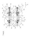
- FIG. 1 Shown in FIG. 1 is a towing vehicle which has an unsigned mark Hanging and Ankupplungsvortechnisch the haymaking machine. 1 draws.
- This haymaking machine 1 is almost in a transport position.
- the left side part 2 of the machine beam 3 in the direction of travel as well as in the direction of travel right side part 4 of the machine beam 3 are in a direction parallel to the direction of travel 5 lying position pivoted.
- the working gyros 6 are not marked in detail, rotated in about vertical axes of rotation. Also not marked are the pivot axes of the following un ownedtten support wheels 7.
- the steered Support wheels 8 are only partially visible in this figure, since they are centrally below the work top 6 are located.
- the by horizontal pivot axes 9 from each other separate single support beams 10 are only partially quantified.
- a steering device 11 per side controls the steered support wheels 8, wherein the Support wheels 8 are pivotable about a pivot axis 12.
- Haymaking machine 1 is not yet in its full transport position, because the steered support wheels 8 have not yet been pivoted in the direction of travel.
- This Einschwenkvorgang can preferably automatically after the side parts. 2 and 4 of the machine beam 3 were swiveled, giving the operating personnel the haymaking machine's job is facilitated.
- Figure 1 is still the common steering device 11 of the support wheels 8 is shown.
- the distance measure A between the vertical center axes of the two in working position inner work top 6 is in the transport position (Fig. 1) increased.
- FIG. 2 steering device 11 has in this embodiment of Invention known lever arms 13 which have at one end joints 14, which are also part of a handlebar 15. Due to the different fixings of the two formed in this example as a hydraulic cylinder actuators 16 to the Lever arms 13 and their different training, the support wheels. 8 synchronously pivoted in the same direction, while a cylinder retracts and the other cylinder extends. This allows the active steering z. B. during the Cornering, since both side parts 2, 4 are pivoted synchronously, or for adjustment various working positions for borderline processing, or for compensation the downhill forces on the machine during a working trip across a Hillside.
- FIG. 3 shows the support wheels 8 is now pivoted in transport position. Besides, here is clearly visible that the handlebar 15, which is parallel to the single support beam 10, with the hinges 14 at their ends, which in this case are ball joints, exactly on a line with the horizontal pivot axes 9 lies.
- FIG. 4 Another inventive design of a haymaking machine 1 has the known frame parts 17 (Fig. 4), which are also only partially quantified as Pull rod element formed on. This will especially in working position occurring in the direction of travel and acting on the side parts 2, 4 absorbed forces and the hay-making machine 1 can drive more stably.
- the joints 18 connecting the individual frame parts 17 are in alignment with one another the ball joints of the steering device 11 and the horizontal pivot axes 9th
- a haymaking machine is created at high speed by means of at least two steered support wheels per left and right side part 2,4 of the machine beam 3 and a possible vertical movement mitbutden Steering device 11 reaches a high stability.
Landscapes
- Life Sciences & Earth Sciences (AREA)
- Environmental Sciences (AREA)
- Engineering & Computer Science (AREA)
- Mechanical Engineering (AREA)
- Soil Sciences (AREA)
- Steering-Linkage Mechanisms And Four-Wheel Steering (AREA)
- Guiding Agricultural Machines (AREA)
- Automobile Manufacture Line, Endless Track Vehicle, Trailer (AREA)
- Jib Cranes (AREA)
- Control Of Multiple Motors (AREA)
- Glass Compositions (AREA)
- Paper (AREA)
Abstract
Description
- Figur 1:
- Eine Heuwerbungsmaschine nach dem Verschwenken in die Transportstellung, wobei die Stützräder noch quer zur Fahrtrichtung stehen.
- Figur 2:
- Ein Ausschnitt aus Fig. 1, welcher die gemeinsamen Lenkvorrichtungen von jeweils zwei in Fahrtrichtung hintereinander liegenden Stützrädem an den Seitenteilen des Maschinenbalkens sowie die zugehörigen und in Arbeitsstellung befindlichen Stützräder zeigt.
- Figur 3:
- Eine Abbildung nach Figur 2 mit in Transportstellung geschwenkten Stützrädern.
- Figur 4:
- Eine Perspektivdarstellung eines Ausschnitts der in Transportstellung befindlichen Heuwerbungsmaschine mit in Fahrtrichtung weisenden Stützrädern.
Claims (10)
- Heuwerbungsmaschine, insbesondere zum Zetten und Wenden, mit an zumindest einem Maschinenbalken (3) angeordneten und über Stützräder (7, 8)auf dem Boden abgestützten Arbeitskreiseln (6), wobei der um im wesentlichen vertikale Schwenkachsen in eine Transportstellung parallel zur Fahrtrichtung schwenkbare Seitenteile (2, 4) aufweisende Maschinenbalken (3) durch horizontale Schwenkachsen (9) in Einzeltragbalken (10) unterteilt ist, dadurch gekennzeichnet, daß in der Transportstellung zumindest zwei an einem Maschinenbalken (3) lenkbar angeordnete Stützräder (8) gemeinsam mit einer Lenkvorrichtung (11) verbunden sind, wobei die Lenkvorrichtung (11) zumindest zwei mit jeweils einer horizontalen Schwenkachse (9) fluchtende Gelenke (14) aufweist.
- Heuwerbungsmaschine nach Anspruch 1, dadurch gekennzeichnet, daß die Lenkvorrichtung (11) an den in etwa vertikalen Schwenkachsen (12) der gelenkten Räder befestigte Hebelarme aufweist, die jeweils endseitig eines der Gelenke (14) aufweisen, wobei die Gelenke (14) der zumindest zwei Hebelarme (13) mit einer Lenkstange (15) verbunden sind.
- Heuwerbungsmaschine nach Anspruch 2, dadurch gekennzeichnet, daß die Hebelarme (13) mit der Lenkstange (15) durch Kugelgelenke miteinander verbunden sind.
- Heuwerbungsmaschine nach einem der Ansprüche 2 oder 3, dadurch gekenn zeichnet, daß ein Stellglied (16) zur Änderung des Lenkeinschlages der gelenkten Stützräder (8) an einem der Hebelarme (13) beweglich befestigt ist.
- Heuwerbungsmaschine nach einem der Ansprüche 1 bis 4, dadurch gekennzeichnet, daß die gelenkten Stützräder (8) durch die Lenkvorrichtung (11) der Heuwerbungsmaschine (1) während der Fahrt aktiv steuerbar ausgeführt sind.
- Heuwerbungsmaschine nach Anspruch 5, dadurch gekennzeichnet, daß die aktiv lenkbaren Stützräder (8) in der Transportstellung zur Geradeausfahrt blockierbar sind.
- Heuwerbungsmaschine nach einem der Ansprüche 5 oder 6, dadurch gekennzeichnet, daß die aktiv lenkbaren Stützräder (8) in der Arbeits- und Betriebsstellung zur Geradeausfahrt blockierbar sind.
- Heuwerbungsmaschine nach einem der Ansprüche 5 bis 7, dadurch gekennzeichnet, daß die aktiv lenkbaren Stützräder (8) nach der Überführung der Seitenteile (2, 4) in ihre Transportstellung durch zumindest eine Steuerungsvorrichtung automatisch in Fahrtrichtung verschwenkbar sind.
- Heuwerbungsmaschine nach einem der Ansprüche 1 bis 8, dadurch gekennzeichnet, daß die lenkbaren Stützräder (8) bezüglich einer in etwa vertikalen Schwenkachse (12) innerhalb eines Lenkwinkelbereiches von mehr als 90° auf vorgebbare Lenkwinkel einstellbar sind.
- Heuwerbungsmaschine nach einem der Ansprüche 1 bis 9 mit in Fahrtrichtung vor und seitlich des Maschinenbalkens an diesem angebrachten Rahmenteilen, welche als Schutzvorrichtung dienen, dadurch gekennzeichnet, daß in Transportstellung die als Zugstangenelement zur Aufnahme von in Arbeitsstellung auf den Maschinenbalken (3) in Fahrtrichtung wirkenden Kräften ausgebildeten Rahmenteile (17) mit den Gelenken (14) der Lenkvorrichtung (11) und den horizontalen Schwenkachsen (9) fluchtende Gelenke (18) aufweist.
Applications Claiming Priority (2)
| Application Number | Priority Date | Filing Date | Title |
|---|---|---|---|
| DE10330385A DE10330385B4 (de) | 2003-07-04 | 2003-07-04 | Heuwerbungsmaschine |
| DE10330385 | 2003-07-04 |
Publications (2)
| Publication Number | Publication Date |
|---|---|
| EP1495667A1 true EP1495667A1 (de) | 2005-01-12 |
| EP1495667B1 EP1495667B1 (de) | 2010-11-17 |
Family
ID=33441626
Family Applications (1)
| Application Number | Title | Priority Date | Filing Date |
|---|---|---|---|
| EP04015481A Expired - Lifetime EP1495667B1 (de) | 2003-07-04 | 2004-07-01 | Heuwerbungsmaschine |
Country Status (3)
| Country | Link |
|---|---|
| EP (1) | EP1495667B1 (de) |
| AT (1) | ATE488126T1 (de) |
| DE (2) | DE10330385B4 (de) |
Cited By (2)
| Publication number | Priority date | Publication date | Assignee | Title |
|---|---|---|---|---|
| FR2892597A1 (fr) * | 2005-10-28 | 2007-05-04 | Kuhn Sa Sa | Machine de fenaison avec des moyens de positionnement des rotors de fanage autour de leur axe central lors du repliage de la machine en position de transport |
| EP4512227A1 (de) * | 2023-08-21 | 2025-02-26 | CLAAS Saulgau GmbH | Heuwerbungsmaschine und verfahren zur einstellung eines abstands eines kreiselkörpers der heuwerbungsmaschine zu einem untergrund |
Citations (4)
| Publication number | Priority date | Publication date | Assignee | Title |
|---|---|---|---|---|
| US3475890A (en) * | 1966-06-24 | 1969-11-04 | Fahr Ag Maschf | Plural rake haying machine with means for adjusting width of swath |
| DE2419749A1 (de) * | 1974-04-24 | 1975-11-06 | Fella Werke Gmbh | Heuwerbungsmaschine |
| DE4008648A1 (de) * | 1989-10-13 | 1991-04-18 | Poettinger Alois Landmasch | Heuwerbungsmaschine |
| EP1108352A1 (de) * | 1999-12-15 | 2001-06-20 | NIEMEYER Landmaschinen GmbH | Heuwerbungsmaschine, insbesondere Vierkreiselschwader |
Family Cites Families (4)
| Publication number | Priority date | Publication date | Assignee | Title |
|---|---|---|---|---|
| AT260598B (de) * | 1964-08-07 | 1968-03-11 | Fahr Ag Maschf | Heuwerbegerät |
| DE9210001U1 (de) * | 1992-07-24 | 1992-09-24 | Greenland GmbH & Co KG, 7702 Gottmadingen | Landwirtschaftliche Maschine |
| DE19525344A1 (de) * | 1995-07-12 | 1997-01-16 | Claas Saulgau Gmbh | Landwirtschaftliche Arbeitsmaschine, insbesondere Vielkreiselheuwender |
| DE19948245A1 (de) * | 1999-10-07 | 2001-04-12 | Josef Nusser | Heumaschine |
-
2003
- 2003-07-04 DE DE10330385A patent/DE10330385B4/de not_active Expired - Fee Related
-
2004
- 2004-07-01 EP EP04015481A patent/EP1495667B1/de not_active Expired - Lifetime
- 2004-07-01 AT AT04015481T patent/ATE488126T1/de active
- 2004-07-01 DE DE502004011892T patent/DE502004011892D1/de not_active Expired - Lifetime
Patent Citations (4)
| Publication number | Priority date | Publication date | Assignee | Title |
|---|---|---|---|---|
| US3475890A (en) * | 1966-06-24 | 1969-11-04 | Fahr Ag Maschf | Plural rake haying machine with means for adjusting width of swath |
| DE2419749A1 (de) * | 1974-04-24 | 1975-11-06 | Fella Werke Gmbh | Heuwerbungsmaschine |
| DE4008648A1 (de) * | 1989-10-13 | 1991-04-18 | Poettinger Alois Landmasch | Heuwerbungsmaschine |
| EP1108352A1 (de) * | 1999-12-15 | 2001-06-20 | NIEMEYER Landmaschinen GmbH | Heuwerbungsmaschine, insbesondere Vierkreiselschwader |
Cited By (3)
| Publication number | Priority date | Publication date | Assignee | Title |
|---|---|---|---|---|
| FR2892597A1 (fr) * | 2005-10-28 | 2007-05-04 | Kuhn Sa Sa | Machine de fenaison avec des moyens de positionnement des rotors de fanage autour de leur axe central lors du repliage de la machine en position de transport |
| WO2007048970A3 (fr) * | 2005-10-28 | 2007-06-14 | Kuhn Sa | Machine de fenaison |
| EP4512227A1 (de) * | 2023-08-21 | 2025-02-26 | CLAAS Saulgau GmbH | Heuwerbungsmaschine und verfahren zur einstellung eines abstands eines kreiselkörpers der heuwerbungsmaschine zu einem untergrund |
Also Published As
| Publication number | Publication date |
|---|---|
| EP1495667B1 (de) | 2010-11-17 |
| DE502004011892D1 (de) | 2010-12-30 |
| ATE488126T1 (de) | 2010-12-15 |
| DE10330385A1 (de) | 2005-05-19 |
| DE10330385B4 (de) | 2010-01-28 |
Similar Documents
| Publication | Publication Date | Title |
|---|---|---|
| EP0212270B1 (de) | Verteilereinrichtung für Häcksler | |
| DE3800235A1 (de) | Vorrichtung zur aufhaengung und lenkung eines landfahrzeugleitrades | |
| EP0394534A1 (de) | Flugzeug-Schlepper ohne Schleppstange (Drehschaufel) | |
| EP0559024B1 (de) | Heuwerbungsmaschine | |
| DE202005015120U1 (de) | Sattelzug oder Anhänger mit verbesserter Lenkung | |
| DE2609252A1 (de) | Erntegutaufnahmetisch- und foerderschnecken-anordnung fuer maehdrescher | |
| EP1495667B1 (de) | Heuwerbungsmaschine | |
| DE2419749A1 (de) | Heuwerbungsmaschine | |
| AT404534B (de) | Heuwerbungsmaschine | |
| DE7905162U1 (de) | Gelenkomnibus | |
| DE3713474C2 (de) | ||
| DE9417893U1 (de) | Mähmaschine | |
| EP3434088B1 (de) | Gezogenes landwirtschaftliches arbeitsgerät | |
| DE10330381B4 (de) | Heuwerbungsmaschine | |
| DE19541872C2 (de) | Selbstfahrende Rübenerntemaschine | |
| DE855659C (de) | Achsschenkelgelenktes Strassenfahrzeug | |
| EP0588027B1 (de) | Selbstfahrende zweiachsige, mehrreihige Rübenerntemaschine | |
| DE10330386B4 (de) | Heuwerbungsmaschine | |
| DE29919104U1 (de) | Heuwerbungsmaschine, insbesondere Kreiselschwader | |
| DE3902003A1 (de) | Koppelvorrichtung fuer eine landmaschine | |
| AT241889B (de) | Hackfruchterntemaschine mit eigenem Fahrwerk | |
| EP0559023A1 (de) | Kreiselrechen für eine Heuwerbungsmaschine | |
| DE19702888A1 (de) | Heumaschine | |
| DE909180C (de) | Schlepper mit lenkbaren, an einer am Gehaeuse oder Rahmen angebrachten Achse gelagerten Raedern | |
| EP1493323A1 (de) | Heuwerbungsmaschine |
Legal Events
| Date | Code | Title | Description |
|---|---|---|---|
| PUAI | Public reference made under article 153(3) epc to a published international application that has entered the european phase |
Free format text: ORIGINAL CODE: 0009012 |
|
| AK | Designated contracting states |
Kind code of ref document: A1 Designated state(s): AT BE BG CH CY CZ DE DK EE ES FI FR GB GR HU IE IT LI LU MC NL PL PT RO SE SI SK TR |
|
| AX | Request for extension of the european patent |
Extension state: AL HR LT LV MK |
|
| 17P | Request for examination filed |
Effective date: 20050623 |
|
| AKX | Designation fees paid |
Designated state(s): AT BE BG CH CY CZ DE DK EE ES FI FR GB GR HU IE IT LI LU MC NL PL PT RO SE SI SK TR |
|
| 17Q | First examination report despatched |
Effective date: 20071214 |
|
| GRAP | Despatch of communication of intention to grant a patent |
Free format text: ORIGINAL CODE: EPIDOSNIGR1 |
|
| GRAS | Grant fee paid |
Free format text: ORIGINAL CODE: EPIDOSNIGR3 |
|
| GRAA | (expected) grant |
Free format text: ORIGINAL CODE: 0009210 |
|
| AK | Designated contracting states |
Kind code of ref document: B1 Designated state(s): AT BE BG CH CY CZ DE DK EE ES FI FR GB GR HU IE IT LI LU MC NL PL PT RO SE SI SK TR |
|
| REG | Reference to a national code |
Ref country code: GB Ref legal event code: FG4D Free format text: NOT ENGLISH |
|
| REG | Reference to a national code |
Ref country code: CH Ref legal event code: EP |
|
| REG | Reference to a national code |
Ref country code: IE Ref legal event code: FG4D |
|
| REF | Corresponds to: |
Ref document number: 502004011892 Country of ref document: DE Date of ref document: 20101230 Kind code of ref document: P |
|
| REG | Reference to a national code |
Ref country code: NL Ref legal event code: VDEP Effective date: 20101117 |
|
| PG25 | Lapsed in a contracting state [announced via postgrant information from national office to epo] |
Ref country code: SE Free format text: LAPSE BECAUSE OF FAILURE TO SUBMIT A TRANSLATION OF THE DESCRIPTION OR TO PAY THE FEE WITHIN THE PRESCRIBED TIME-LIMIT Effective date: 20101117 Ref country code: CY Free format text: LAPSE BECAUSE OF FAILURE TO SUBMIT A TRANSLATION OF THE DESCRIPTION OR TO PAY THE FEE WITHIN THE PRESCRIBED TIME-LIMIT Effective date: 20101117 Ref country code: FI Free format text: LAPSE BECAUSE OF FAILURE TO SUBMIT A TRANSLATION OF THE DESCRIPTION OR TO PAY THE FEE WITHIN THE PRESCRIBED TIME-LIMIT Effective date: 20101117 Ref country code: PT Free format text: LAPSE BECAUSE OF FAILURE TO SUBMIT A TRANSLATION OF THE DESCRIPTION OR TO PAY THE FEE WITHIN THE PRESCRIBED TIME-LIMIT Effective date: 20110317 Ref country code: NL Free format text: LAPSE BECAUSE OF FAILURE TO SUBMIT A TRANSLATION OF THE DESCRIPTION OR TO PAY THE FEE WITHIN THE PRESCRIBED TIME-LIMIT Effective date: 20101117 Ref country code: SI Free format text: LAPSE BECAUSE OF FAILURE TO SUBMIT A TRANSLATION OF THE DESCRIPTION OR TO PAY THE FEE WITHIN THE PRESCRIBED TIME-LIMIT Effective date: 20101117 Ref country code: BG Free format text: LAPSE BECAUSE OF FAILURE TO SUBMIT A TRANSLATION OF THE DESCRIPTION OR TO PAY THE FEE WITHIN THE PRESCRIBED TIME-LIMIT Effective date: 20110217 |
|
| REG | Reference to a national code |
Ref country code: IE Ref legal event code: FD4D |
|
| PG25 | Lapsed in a contracting state [announced via postgrant information from national office to epo] |
Ref country code: GR Free format text: LAPSE BECAUSE OF FAILURE TO SUBMIT A TRANSLATION OF THE DESCRIPTION OR TO PAY THE FEE WITHIN THE PRESCRIBED TIME-LIMIT Effective date: 20110218 |
|
| PG25 | Lapsed in a contracting state [announced via postgrant information from national office to epo] |
Ref country code: CZ Free format text: LAPSE BECAUSE OF FAILURE TO SUBMIT A TRANSLATION OF THE DESCRIPTION OR TO PAY THE FEE WITHIN THE PRESCRIBED TIME-LIMIT Effective date: 20101117 Ref country code: ES Free format text: LAPSE BECAUSE OF FAILURE TO SUBMIT A TRANSLATION OF THE DESCRIPTION OR TO PAY THE FEE WITHIN THE PRESCRIBED TIME-LIMIT Effective date: 20110228 Ref country code: IE Free format text: LAPSE BECAUSE OF FAILURE TO SUBMIT A TRANSLATION OF THE DESCRIPTION OR TO PAY THE FEE WITHIN THE PRESCRIBED TIME-LIMIT Effective date: 20101117 |
|
| PG25 | Lapsed in a contracting state [announced via postgrant information from national office to epo] |
Ref country code: PL Free format text: LAPSE BECAUSE OF FAILURE TO SUBMIT A TRANSLATION OF THE DESCRIPTION OR TO PAY THE FEE WITHIN THE PRESCRIBED TIME-LIMIT Effective date: 20101117 Ref country code: RO Free format text: LAPSE BECAUSE OF FAILURE TO SUBMIT A TRANSLATION OF THE DESCRIPTION OR TO PAY THE FEE WITHIN THE PRESCRIBED TIME-LIMIT Effective date: 20101117 Ref country code: DK Free format text: LAPSE BECAUSE OF FAILURE TO SUBMIT A TRANSLATION OF THE DESCRIPTION OR TO PAY THE FEE WITHIN THE PRESCRIBED TIME-LIMIT Effective date: 20101117 Ref country code: SK Free format text: LAPSE BECAUSE OF FAILURE TO SUBMIT A TRANSLATION OF THE DESCRIPTION OR TO PAY THE FEE WITHIN THE PRESCRIBED TIME-LIMIT Effective date: 20101117 |
|
| PLBE | No opposition filed within time limit |
Free format text: ORIGINAL CODE: 0009261 |
|
| STAA | Information on the status of an ep patent application or granted ep patent |
Free format text: STATUS: NO OPPOSITION FILED WITHIN TIME LIMIT |
|
| 26N | No opposition filed |
Effective date: 20110818 |
|
| REG | Reference to a national code |
Ref country code: DE Ref legal event code: R097 Ref document number: 502004011892 Country of ref document: DE Effective date: 20110818 |
|
| PG25 | Lapsed in a contracting state [announced via postgrant information from national office to epo] |
Ref country code: IT Free format text: LAPSE BECAUSE OF FAILURE TO SUBMIT A TRANSLATION OF THE DESCRIPTION OR TO PAY THE FEE WITHIN THE PRESCRIBED TIME-LIMIT Effective date: 20101117 |
|
| BERE | Be: lapsed |
Owner name: MASCHINENFABRIK BERNARD KRONE G.M.B.H. Effective date: 20110731 |
|
| PG25 | Lapsed in a contracting state [announced via postgrant information from national office to epo] |
Ref country code: MC Free format text: LAPSE BECAUSE OF NON-PAYMENT OF DUE FEES Effective date: 20110731 |
|
| REG | Reference to a national code |
Ref country code: CH Ref legal event code: PL |
|
| GBPC | Gb: european patent ceased through non-payment of renewal fee |
Effective date: 20110701 |
|
| PG25 | Lapsed in a contracting state [announced via postgrant information from national office to epo] |
Ref country code: LI Free format text: LAPSE BECAUSE OF NON-PAYMENT OF DUE FEES Effective date: 20110731 Ref country code: BE Free format text: LAPSE BECAUSE OF NON-PAYMENT OF DUE FEES Effective date: 20110731 Ref country code: CH Free format text: LAPSE BECAUSE OF NON-PAYMENT OF DUE FEES Effective date: 20110731 |
|
| PG25 | Lapsed in a contracting state [announced via postgrant information from national office to epo] |
Ref country code: GB Free format text: LAPSE BECAUSE OF NON-PAYMENT OF DUE FEES Effective date: 20110701 |
|
| PG25 | Lapsed in a contracting state [announced via postgrant information from national office to epo] |
Ref country code: LU Free format text: LAPSE BECAUSE OF NON-PAYMENT OF DUE FEES Effective date: 20110701 |
|
| PG25 | Lapsed in a contracting state [announced via postgrant information from national office to epo] |
Ref country code: EE Free format text: LAPSE BECAUSE OF NON-PAYMENT OF DUE FEES Effective date: 20101117 |
|
| PG25 | Lapsed in a contracting state [announced via postgrant information from national office to epo] |
Ref country code: TR Free format text: LAPSE BECAUSE OF FAILURE TO SUBMIT A TRANSLATION OF THE DESCRIPTION OR TO PAY THE FEE WITHIN THE PRESCRIBED TIME-LIMIT Effective date: 20101117 |
|
| PG25 | Lapsed in a contracting state [announced via postgrant information from national office to epo] |
Ref country code: HU Free format text: LAPSE BECAUSE OF FAILURE TO SUBMIT A TRANSLATION OF THE DESCRIPTION OR TO PAY THE FEE WITHIN THE PRESCRIBED TIME-LIMIT Effective date: 20101117 |
|
| REG | Reference to a national code |
Ref country code: FR Ref legal event code: PLFP Year of fee payment: 13 |
|
| REG | Reference to a national code |
Ref country code: FR Ref legal event code: PLFP Year of fee payment: 14 |
|
| REG | Reference to a national code |
Ref country code: FR Ref legal event code: PLFP Year of fee payment: 15 |
|
| REG | Reference to a national code |
Ref country code: DE Ref legal event code: R084 Ref document number: 502004011892 Country of ref document: DE |
|
| PGFP | Annual fee paid to national office [announced via postgrant information from national office to epo] |
Ref country code: DE Payment date: 20200702 Year of fee payment: 17 Ref country code: FR Payment date: 20200723 Year of fee payment: 17 |
|
| PGFP | Annual fee paid to national office [announced via postgrant information from national office to epo] |
Ref country code: AT Payment date: 20200710 Year of fee payment: 17 |
|
| REG | Reference to a national code |
Ref country code: DE Ref legal event code: R119 Ref document number: 502004011892 Country of ref document: DE |
|
| REG | Reference to a national code |
Ref country code: AT Ref legal event code: MM01 Ref document number: 488126 Country of ref document: AT Kind code of ref document: T Effective date: 20210701 |
|
| PG25 | Lapsed in a contracting state [announced via postgrant information from national office to epo] |
Ref country code: DE Free format text: LAPSE BECAUSE OF NON-PAYMENT OF DUE FEES Effective date: 20220201 Ref country code: AT Free format text: LAPSE BECAUSE OF NON-PAYMENT OF DUE FEES Effective date: 20210701 |
|
| PG25 | Lapsed in a contracting state [announced via postgrant information from national office to epo] |
Ref country code: FR Free format text: LAPSE BECAUSE OF NON-PAYMENT OF DUE FEES Effective date: 20210731 |