EP1494414A2 - Verfahren und System zum Bereitstellen von virtuellen Zwischenschichtprotokollen - Google Patents
Verfahren und System zum Bereitstellen von virtuellen Zwischenschichtprotokollen Download PDFInfo
- Publication number
- EP1494414A2 EP1494414A2 EP04010104A EP04010104A EP1494414A2 EP 1494414 A2 EP1494414 A2 EP 1494414A2 EP 04010104 A EP04010104 A EP 04010104A EP 04010104 A EP04010104 A EP 04010104A EP 1494414 A2 EP1494414 A2 EP 1494414A2
- Authority
- EP
- European Patent Office
- Prior art keywords
- protocol
- interlayer
- address
- layer
- data
- Prior art date
- Legal status (The legal status is an assumption and is not a legal conclusion. Google has not performed a legal analysis and makes no representation as to the accuracy of the status listed.)
- Withdrawn
Links
Images


Classifications
-
- H—ELECTRICITY
- H04—ELECTRIC COMMUNICATION TECHNIQUE
- H04L—TRANSMISSION OF DIGITAL INFORMATION, e.g. TELEGRAPHIC COMMUNICATION
- H04L69/00—Network arrangements, protocols or services independent of the application payload and not provided for in the other groups of this subclass
-
- G—PHYSICS
- G06—COMPUTING; CALCULATING OR COUNTING
- G06F—ELECTRIC DIGITAL DATA PROCESSING
- G06F15/00—Digital computers in general; Data processing equipment in general
- G06F15/16—Combinations of two or more digital computers each having at least an arithmetic unit, a program unit and a register, e.g. for a simultaneous processing of several programs
Definitions
- the present invention is related generally to computer network communications, and, more particularly, to layered communications protocols.
- Modem computer network systems are growing to be very complex, involving many disparate communications tasks in addition to the basic task of moving messages from one computer to another.
- communications protocols are divided into "layers," with each layer handling some important communications tasks while leaving other tasks to other layers.
- the International Standards Organization Open Systems Interconnection (ISO/OSI) protocol model is a theoretical construct which assigns communications tasks among the model's "stack" of seven layers.
- the overall task of enabling network communications is divided into subtasks and those subtasks are each assigned to a logical layer in the protocol stack.
- the stack is hierarchical: Each layer has a defined interface with the layers above and below it (except, of course, for the uppermost and lowermost layers).
- each layer communicates with its peer layer on another computer, provides services to the layer above it in the stack, and uses the services provided by the layer below it.
- messages flow down the stack from their source until the physical layer actually transmits them across the medium of the network connection.
- messages are received by their intended recipient computer, they are passed up the stack with each layer stripping off and responding to the data meant for it while passing the rest of the messages up to the next level.
- the network layer (layer 3) defines how messages are routed among networks.
- the network layer on one computer logically speaks with the network layer on another computer by passing a packet of data down to the data layer (layer 2) on its own computer.
- the data layer in turn adds a header to the network layer's packet thus creating a data frame which it passes to the physical layer (layer 1).
- the physical layer uses the physical network medium to transmit that data frame.
- the recipient's data layer reads the data frame, stripping from it the header information meant for its own use.
- the data layer takes the rest of the frame, consisting of the source computer's data packet, and sends it up to the network layer.
- the network layer on the recipient reads the packet as sent by the network layer on the source without having to decode the data layer header and other information used by the lower layers to transmit the data packet.
- each protocol layer can communicate with its peers without concerning itself with the myriad details handled by other layers in the protocol stack. That is, each layer performs its communications tasks mostly independently of the tasks performed by the other layers.
- This promises flexibility in implementation.
- a particular implementation of one layer e.g., an Institute of Electrical and Electronics Engineers (IEEE) 802 Ethernet Data Layer 2
- IEEE Institute of Electrical and Electronics Engineers 802 Ethernet Data Layer 2
- any number of implementations of the protocol layer above it e.g., multiple ISO/OSI Internetworking Protocol Layer 3s.
- a new layer 3 protocol can be introduced to advance the art of network communications while at the same time remaining compatible with the installed infrastructure of layer 2 devices.
- a given upper protocol layer operates over multiple disparate lower layers.
- one computer can run a single layer 3 over both an Ethernet layer 2 interface and a wireless interface. This flexibility has enabled layered protocols to survive and to grow for over twenty years.
- devices can communicate directly with other devices (“local devices") within the network and can communicate directly with a router for sending data to devices (“remote devices”) beyond the boundaries of the local network.
- local devices devices
- remote devices devices
- a device in a wireless network may not be able to directly communicate with all of the other local devices due to noise, interference, and distance between the devices.
- a device may not be able to communicate directly with a router that connects the wireless network to the wired Internet.
- a wireless device can have difficulties in sending messages both to local and to remote devices.
- wireless devices help one another by retransmitting intercepted messages intended for other devices. This allows a message sent by a source device to "hop" or pass through several intermediary devices before arriving at the intended recipient.
- Source routing generally works as advertised, but it well illustrates the intra-layer compatibility problems of layered protocols. The problems arise when deciding where within the layered protocol stack to place source routing. If the source routing protocol is made a part of the layer 3 protocol, and thus uses layer 3 addresses, then the layered protocol model allows the source routing protocol to work with multiple layer 2s. This is a significant advantage when devices in a network use different wireless protocols or when the network includes both wired and wireless devices (or when a single device has both a wired and a wireless network interface). However, as mentioned above, different layer 3 protocols do not necessarily work with one another. Thus, a layer 3 source route developed for, say, the IPv4 layer 3 protocol would not work with devices using other layer 3 protocols such as IPv6 and IPX.
- layered protocol systems In order to develop and to address new communications tasks, layered protocol systems must accommodate new protocols at each layer.
- the layered model helps to make sure that a new protocol is compatible with other protocols above and below it in the protocol stack.
- incompatibility of protocols within a given layer hinders the full realization of the promise of layered protocols.
- the present invention provides a virtual protocol "interlayer" between two protocol layers in a communications stack.
- an interlayer to handle the task.
- An addressing scheme peculiar to the interlayer is set up. The interlayer frees the other layers in the protocol stack to operate as before, leaving to the interlayer the specifics of performing the communications task.
- protocol interlayer The details of the operation of a protocol interlayer are dependent upon the particulars of the task, or tasks, it is called upon to perform. If necessary, one communicating device can simultaneously support more than one interlayer, although performance issues could hinder the multiplication of interlayers.
- each network interface on each network device is assigned its own globally unique interlayer address
- interface identifiers can be added to the interlayer address to distinguish among multiple network interfaces on a network device.
- a protocol interlayer is introduced with no change to the protocol layers above and below it.
- the interlayer presents to the layer above it (e.g., layer 3) the same interface presented by the layer below it (e.g., layer 2).
- the existing upper protocol layer interacts with the interlayer just as it used to interact with the lower protocol layer.
- Other embodiments require just a small change to a protocol layer adjacent to the interlayer. For example, a new protocol header flag in a received message can be recognized by a lower layer, using existing techniques, causing the lower layer to pass the message on to the interlayer rather than process the message itself or pass it on to the upper layer.
- Source routing is a useful example for demonstrating the utility of the protocol interlayer.
- an interlayer is built between the ISO/OSI protocol layers 2 and 3. Source routing is performed within this interlayer, using interlayer addresses.
- interlayer addresses rather than layer 2 or layer 3 addresses, this embodiment of source routing allows compatibility both with multiple layer 3 protocols and with multiple layer 2 network interfaces.
- Figure 1 is a block diagram of a communications environment supporting both wired and wireless hosts
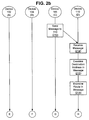
- Figures 2a through 2c together form a dataflow diagram illustrating how, by using a source route, two hosts in Figure 1 can communicate with one another via an intermediary device;
- Figure 3 is a data structure diagram of a source route that uses interlayer addresses
- Figure 4 is a schematic diagram generally illustrating an exemplary computer system that supports the present invention
- Figure 5a is a logical diagram of the International Standards Organization Open Systems Interconnection (ISO/OSI) model for hierarchically-layered, network communications protocols;
- Figure 5b is a block diagram showing some of the communications tasks involved in running an ISO/OSI protocol stack;
- ISO/OSI International Standards Organization Open Systems Interconnection
- Figure 6 is a schematic diagram presenting one possible software implementation for performing the tasks described with respect to Figure 5b;
- Figure 7 is a flowchart showing an exemplary method according to the present invention for an upper protocol layer to interact with a protocol interlayer
- Figure 8 is a data structure diagram of an address association table
- Figures 9a and 9b together form a flowchart of an exemplary protocol interlayer responding to a message received from an upper protocol layer;
- Figure 10 is a flowchart of a method usable by an exemplary lower protocol layer when receiving a message intended for a protocol interlayer
- Figure 11 is a data structure diagram of an exemplary data frame containing an interlayer header
- FIGS. 12a and 12b together form a flowchart of an exemplary protocol interlayer responding to a message received from a lower protocol layer;
- Figure 13 is a flowchart of an exemplary method for assigning and discovering interlayer addresses.
- Figures 14a and 14b together form a dataflow diagram showing how the Address Resolution Protocol can work in the presence of a protocol interlayer.
- the present invention provides a virtual protocol "interlayer" between two protocol layers in a communications stack.
- an interlayer is created, with its own addressing scheme, to handle the task.
- Source routing is a useful example for demonstrating the utility of the protocol interlayer.
- an interlayer is built between the ISO/OSI protocol layers 2 and 3.
- Source routing is performed within this interlayer, using interlayer addresses.
- interlayer addresses rather than layer 2 or layer 3 addresses, this embodiment of source routing allows compatibility both with multiple layer 3 protocols and with multiple layer 2 network interfaces.
- the utility of the present invention is not limited to source routing, however: Protocol interlayers can be developed to perform other communications tasks as well.
- Source routing is a set of techniques developed for situations where traditional routing methods do not apply. First, consider how traditional routing works. For a device on a traditional, wired network, all other devices are divided into two general classes. "Local” devices are locating with the same local network and can be accessed directly. "Remote” devices lie beyond the boundaries of the local network and are accessed through a router. The router is a local device. Traditional routing methods are based on this dichotomy of local and remote devices. When sending to a local device, the source device simply addresses the message to the intended recipient and puts the message out onto the local network. All local devices, including the intended recipient, receive the message. (This simplistic view does not always hold in real networks.
- Ethernet switches do not propagate Ethernet frames to local links that do not contain the addressed device.
- the simplistic view holds for purposes of illustration.
- the manner in which Ethernet switches discover the locations of local devices and limit retransmissions accordingly is an excellent example of "ad hoc" routing in a non-wireless network.) All local devices, except the intended recipient, then discard the message. The intended recipient reads the message and responds accordingly.
- the source device (or, more likely, a router on the source device's network) considers the shortest path to the intended recipient and sends the source's message on to the next device on that shortest path.
- the next device examines the recipient address and either accepts the message, if this device is the intended recipient, or again applies the shortest path algorithm to send the message along.
- the message arrives at the intended recipient.
- Routers periodically share end-to-end network topology information to allow each of them to correctly choose the shortest path.
- the device 106 In the "ad hoc" wireless network 100, devices 102, 104, and 106 can all communicate wirelessly with one another (as implied by the elongated "Z"s). (In this context, “ad hoc" means that there is no central configuration management for the network 100 and thus, no central repository for the address and topological information relied on so heavily by traditional routing algorithms.)
- the device 106 also has a wired local area network (LAN) connection 108 to another device 110. That device 110 is, among other things, a router that connects the ad hoc wireless network 100 to the Internet 112. However, because this device 110 has no wireless receiver, wireless-only devices 102 and 104 cannot communicate directly with it, nor, without some assistance, can they communicate through the router 110 to the Internet 112.
- LAN local area network
- the wireless devices help one another by retransmitting intercepted messages intended for other devices.
- This allows a message sent by a source device to "hop" or pass through several intermediary devices before arriving at the intended recipient.
- Source routing protocols form one set of approaches to prevent transmission "loops" wherein a message passes through the same intermediary device more than once on its way to the intended recipient.
- the source device discovers a route, potentially through several intermediary devices, to the intended recipient. Only devices along the source route retransmit intercepted messages, thus enabling delivery while reducing inefficient excess rebroadcast traffic. While, for purposes of clarity, the present discussion uses source routing to illustrate the methods of the present invention, those methods are equally applicable to the non-source routing approaches to this problem that have also been developed.
- FIG. 2a through 2c illustrates a simple source routing scenario. This scenario is first presented at a very high level. Then, following the discussion of Figure 6, the scenario is revisited with more attention paid to addressing details.
- the device 102 wishes to send a message to the device 110.
- the nature of the message is not important for this discussion; it could be intended for an application running on the device 110 or it could sent to the device 110 in order to be routed to another device on the Internet 112. In any case, the device 102 cannot communicate directly with the device 110 so, in step 200 of Figure 2a, the device 102 discovers a source route to the device 110.
- the discovered source route passes through the device 106, with which the device 102 can directly communicate and which can in turn communicate directly with the device 110.
- Many protocols exist for discovering this source route and their complexities are beyond the scope of the present discussion.
- Figure 3 illustrates the source route 300.
- the source route 300 begins at the source device 102 (field 302), and then goes to the device 106 (field 304).
- the field 304 also specifies which of those two interfaces will receive the message from the previous device on the source route 300.
- the wireless interface of the device 106 is to receive the message from the wireless-only device 102.
- the next entry, or "hop,” in the source route 300 specifies how the message is to leave the device 106 (field 306). The message is to leave via the LAN interface. The next hop is the final one, the intended recipient, the device 110 specified in field 308.
- the format and contents of the source route can vary among the various source routing protocols so Figure 3 is intended merely to illustrate the concepts of a source route.
- some source routes would include only the intermediate fields 304 and 306 and would consider the source and destination fields 302 and 308, respectively, not to be part of the source route itself.
- an actual source route can be quite a bit more complex than the simple example of Figure 3.
- the device 102 creates its message intended for the device 110 and includes in it the source route 300.
- the message is addressed to the next hop on the source route, in'this case device 106.
- the message is transmitted into the wireless communications network 100.
- Both of the other wireless devices 104 and 106 receive the message in step 204 and then examine the message's destination address in step 206. Note that this next hop destination is NOT, in general, the ultimate recipient address in the source route 300. Because that destination address does not match that of the device 104, that device discards the message in step 208.
- the destination address does match that of the device 106, so that device proceeds, in step 210, to examine the message, particularly the source route 300.
- the device 106 discovers that it is not the intended recipient of this message. So, in step 212 of Figure 2b, the device 106 finds the next hop in the source route 300, the device 110, and sends the message on.
- the device 110 receives the message in step 214 and examines the destination address in step 216. Because that address matches that of the device 110, the device 110 proceeds, in step 218, to examine the source route 300 in the message. In step 220 of Figure 2c, the device 110 realizes that it is the intended recipient of the message. The device 110 processes the contents of the message as appropriate.
- FIG. 4 is a block diagram generally illustrating an exemplary computer system that supports the present invention.
- the computer system of Figure 4 is only one example of a suitable environment and is not intended to suggest any limitation as to the scope of use or functionality of the invention. Neither should the device 102 be interpreted as having any dependency or requirement relating to any one or combination of components illustrated in Figure 4.
- the invention is operational with numerous other general-purpose or special-purpose computing environments or configurations.
- the device 102 typically includes at least one processing unit 400 and memory 402.
- the memory 402 may be volatile (such as RAM), non-volatile (such as ROM or flash memory), or some combination of the two. This most basic configuration is illustrated in Figure 4 by the dashed line 404.
- the device 102 may have additional features and functionality.
- the device 102 may include additional storage (removable and non-removable) including, but not limited to, magnetic and optical disks and tape.
- additional storage is illustrated in Figure 4 by removable storage 406 and by non-removable storage 408.
- Computer-storage media include volatile and non-volatile, removable and non-removable, media implemented in any method or technology for storage of information such as computer-readable instructions, data structures, program modules, or other data.
- Memory 402, removable storage 406, and non-removable storage 408 are all examples of computer-storage media.
- Computer-storage media include, but are not limited to, RAM, ROM, EEPROM, flash memory, other memory technology, CD-ROM, digital versatile disks, other optical storage, magnetic cassettes, magnetic tape, magnetic disk storage, other magnetic storage devices, and any other media that can be used to store the desired information and that can be accessed by the device 102. Any such computer-storage media may be part of the device 102.
- the device 102 may also contain communications channels 410 that allow the device to communicate with other devices. Communications channels 410 are examples of communications media. Communications media typically embody computer-readable instructions, data structures, program modules, or other data in a modulated data signal such as a carrier wave or other transport mechanism and include any information delivery media.
- modulated data signal means a signal that has one or more of its characteristics set or changed in such a manner as to encode information in the signal.
- communications media include wired media, such as wired networks and direct-wired connections, and wireless media such as acoustic, RF, infrared, and other wireless media.
- computer-readable media includes both storage media and communications media.
- the device 102 may also have input devices 412 such as a keyboard, mouse, pen, voice-input device, tablet, touch-input device, etc.
- Output devices 414 such as a display (which may be integrated with a touch-input device), speakers, and printer may also be included. All these devices are well known in the art and need not be discussed at length here.
- the network devices 102, 104, 106, and 110 can use any of a number of communications protocols.
- many, but not quite all, of today's communications protocols follow the ISO/OSI protocol model, shown in Figure 5a.
- the overall task of enabling network communications is divided into subtasks, and those subtasks are each assigned to a logical layer in the protocol stack.
- each layer communicates with its peer layer on another device, provides services to the layer above it in the stack, and uses the services provided by the layer below it.
- messages flow down the stack from their originator until the physical layer 500 actually transmits them across the medium of the network connection, shown here as the LAN 108.
- each protocol layer can communicate with its peers without concerning itself with the myriad details handled by other layers in the protocol stack. That is, each layer performs its communications tasks mostly independently of the tasks performed by the other layers.
- the ISO/OSI model does not specify how the device 102 should internally implement the tasks required to support an ISO/OSI layered communications protocol.
- Figure 5b shows one possible implementation of the tasks supporting the popular Transmission Control Protocol/Internet Protocol (TCP/IP) stack.
- TCP/IP Transmission Control Protocol/Internet Protocol
- communications flow up and down a stack of computing components that is closely analogous to the layered stack in the ISO/OSI model.
- Network communications services are presented to the application program 506 by a socket layer 510.
- the socket layer 510 insulates the application program 506 from the details of the ISO/OSI communications protocol. This insulation is especially valuable when a device, such as the device 106, is connected to more than one network and is running more than one communications protocol.
- a complicated protocol such as TCP/IP requires several tasks beyond the simple transport of data.
- these functions are represented by the 802.1X component 512, which provides authentication services, and by the Dynamic Host Configuration Protocol component 514, which provides for non-static layer 3 addresses.
- FIG. 6 portrays one possible software implementation that supports the communications tasks of an ISO/OSI protocol.
- application programs 506 are running on the device 106. They communicate through a Layered Server Provider 600 to the standard communications hardware and software provided by the device 106.
- a network protocol stack 602 with its internal buffers, handles communications tasks.
- An input/output manager 604 sets up and tears down communications channels.
- the network protocol stack 602 talks to a hardware abstraction layer 606 which in turn talks to a network interface 608 that runs the LAN communications link 108.
- Another network interface (not shown) runs the device 106's wireless link.
- the destination addresses used in each hop are layer 2 addresses.
- these addresses are unique within a local network, but may not be globally unique.
- Different types of networks e.g., the wired LAN 108 vs. the wireless network 100
- a message created by layer 3 or by any higher layer includes the layer 3 addresses of the source and of the intended recipient.
- Figure 3 says that the example source route 300 uses protocol interlayer addresses.
- Prior art source routing protocols use either layer 2 addresses or layer 3 addresses.
- a source route is only intelligible to the protocol layer that provides its addresses.
- the source route would be examined (in steps 210 and 218) by a layer 2 protocol driver 518.
- a layer 3 address-based source route would be examined by a layer 3 protocol driver 516 in those steps.
- the choice of where to place the source routing protocol within the ISO/OSI protocol stack is important because each choice presents both advantages and disadvantages due to the intra-layer compatibility problems of layered protocols.
- Figure 7 shows how the layer 3 protocol driver 516 of the device 102 begins the scenario.
- the methods of Figure 7 occur before step 200 of Figure 2a.
- step 700 a layer 3 data packet is created containing the layer 3 addresses of the source (the device 102) and of the intended recipient (the device 110). Because the lower protocol layers cannot route the data packet using layer 3 addresses, these addresses are translated in step 702 into addresses specified by the protocol interlayer.
- This translation process can be a simple lookup into an address association table such as that depicted in Figure 8.
- the 'layer 3 (IP) address of a device is used as a key to locate a record that includes the interlayer address for that same device. Note that the layer 3 protocol driver 516 need not understand the format of interlayer addresses: It can simply pull the values from the table 800.
- step 704 the layer 3 protocol driver 516 delivers the layer 3 data packet along with the interlayer source and destination addresses to a protocol interlayer.
- the layer 3 protocol driver 516 can follow the procedure of Figure 7 without being altered in the slightest way to accommodate the protocol interlayer.
- the layer 3 protocol driver 516 could believe that, in step 702, it is calling for layer 2 addresses. This call is intercepted and interlayer addresses are returned instead.
- the layer 3 protocol driver 516 could believe that in step 704 it is delivering the layer 3 data packet to a layer 2 protocol driver 518 instead of to the protocol interlayer.
- the binding of the layer 3 and 2 protocols layers is arranged so that the protocol interlayer looks exactly like just another layer 2 protocol driver 518 to the layer 3 protocol driver 516. This is an example where a protocol interlayer can be introduced with no change whatsoever to the protocol driver above it. This possibility has decided advantages for compatibility and widespread implementation.
- the protocol interlayer receives the data packet from layer 3 in step 900 of Figure 9a. As the received interlayer source address will be unintelligible to the layer 2 protocol driver 518, the interlayer translates this address into a layer 2 source address in step 902. (Actually this translation step is optional because the layer 2 protocol driver 518 probably knows its own layer 2 address.) The translation can use the address association table 800 of Figure 8.
- the protocol interlayer first determines whether to apply the methods of source routing to the present data packet. If for example, a layer 3 data packet is generated at the device 106 and is intended for the device 110, then the LAN 108 will carry the packet directly, and no source routing is needed. In the scenario of Figures 2a through 2c, on the other hand, source routing is needed to transport the data packet from the source device 102 to the recipient device 110. Knowing this, the protocol interlayer in step 904 (which corresponds to step 200 of Figure 2a) locates an appropriate source route. The details of this step depend upon the source routing protocol used and can be very complex. The device 102 may have already stored an appropriate source route in a table, so that it can simply retrieve the route in step 904. If not, then the device 102 can discover a route by querying the devices around it. In this example, the located source route goes through the device 106 and uses interlayer addresses as shown in Figure 3.
- step 906 the protocol interlayer adds its own header to the layer 3 data packet to create an interlayer data frame.
- An exemplary format for the interlayer header is discussed below in reference to Figure 11.
- the protocol interlayer translates the interlayer address of the next hop into a layer 2 address in step 908. If source routing is not appropriate (e.g., the device 106 is sending directly to the device 110), then the next hop is the recipient device. For a message with a source route, the address is the layer 2 address of the next device in the route. In the present scenario, this is the layer 2 address of the device 106.
- the protocol interlayer uses the interface index of the interlayer address of the next hop in order to choose a specific layer 2 protocol driver 518 to use to send the message. This step applies when the sending device has more than one layer 2 interface. In the present scenario, this step does not apply to the device 102 because it has only one layer 2 interface.
- the layer 3 data packet, its attached interlayer header, the source layer 2 address, and the layer 2 address of the next hop are delivered to the chosen layer 2 protocol driver 518 in step 912 of Figure 9b.
- Steps 914 and 916 are optional but are specified by some source routing protocols.
- a timer is associated with the data packet delivered to the layer 2 protocol driver 518 in step 912. If no indication of successful delivery is received (while could come from the intended recipient or from an intermediary device on the source route), then the sending device knows that something is wrong with its chosen source route. This is a common occurrence in ad hoc networks where devices on a chosen source route can move out of range or disappear entirely. If the timer expires, then the source device applies methods specified by the source routing protocol to fix or to replace the source route. The message is then resent using the new source route.
- the layer 2 protocol driver 518 When the layer 2 protocol driver 518 receives the message from the protocol interlayer, it proceeds just as it would had it received the message from the layer 3 protocol driver 516 instead.
- the layer 2 data frame addressed to the device 106 and including the layer 3 data packet and the interlayer header, is transmitted by the device 102's wireless transmitter in step 202 of Figure 2a.
- step 204 at the devices 104 and 106 and step 214 at the device 110 there are two places where a layer 2 data frame is received over a network connection: step 204 at the devices 104 and 106 and step 214 at the device 110.
- the receiving layer 2 protocol driver 518 can use the procedure of Figure 10.
- the layer 2 data frame is received in step 1000 and is processed according to the normal practices of the appropriate layer 2 protocol in step 1002. These practices include comparing the layer 2 destination address in the frame against the address of the current device. (This comparison is performed in steps 206 and 216.) After performing this comparison, the device 104 notes the difference, and, because the data frame is not intended for it, discards the data frame in step 208. Note that because this discard is performed under normal layer 2 practices, it does not rely upon the source route contained in the message.
- the layer 2 destination address comparisons of step 206 on the device 106 and of step 216 on the device 110 reveals that these devices are the intended destinations of the received data frame. Therefore, these devices proceed, in step 1004 of Figure 10, to examine the contents of the data frame. The examination reveals that the data frame contains an interlayer header such as 1104 in Figure 11. Because layer 2 protocols are designed to support multiple, simultaneous layer 3 protocols, these protocols specify values for a flag that tells the layer 2 protocol driver 518 to which layer 3 protocol driver 516 the data frame should be directed. In the present embodiment, that flag is the field 1106. The flag is given a value associated with the interlayer.
- the layer 2 protocol driver 518 reads the flag 1106 and responds to its value just like it responds to other values of the flag.
- the data frame 1100 is passed up to the protocol interlayer just as if the protocol interlayer were simply another layer 3 protocol driver 516. If a data frame is received with no interlayer header, then the layer 2 protocol driver 518 examines the frame for a layer 3 packet in step 1008 and, if one is found, delivers the layer 3 packet to the appropriate layer 3 protocol driver 516 (as determined by the value of the flag) in step 1010.
- the introduction of the protocol interlayer only changes the layer 2 protocol driver 518 in that it now must recognize the presence of an interlayer header in step 1004 and deliver it as appropriate.
- Layer 2 protocols are already familiar with many types of layer 3 flag values, so that this change is simply one of adding another universally recognized value for the flag (in field 1106) to those already recognized by the layer 2 protocol driver 518.
- the presence of the interlayer does not necessitate all messages passing through it, but that (as in steps 1008 and 1010) messages can still be passed directly from layer 2 to layer 3 if necessary.
- the protocol interlayer receives the data frame 1100 from the layer 2 protocol driver 518 in steps 210 and 218 on the devices 106 and 110, respectively.
- the receiving interlayers apply the method of Figures 12a and 12b.
- the data frame 1100 with its interlayer header 1104 is received in step 1200.
- the device applies the appropriate methods defined by its source routing protocol.
- the receiving device examines the destination interlayer address 308 in the interlayer header 1104. Note that, unlike the layer 2 destination address examined in steps 206 and 216 above, this is the address of the ultimate recipient of the message.
- the destination interlayer address 308 is compared against the interlayer address assigned to the current device in step 1206. On the device 110 (in step 218 of Figure 2b), this comparison reveals that this device 110 is the intended recipient of the message.
- the message is then passed on to the layer 3 protocol driver 516 in step 1208 which processes it accordingly (step 220 of Figure 2c).
- step 1206 When the comparison of step 1206 is performed on the device 106, however, this device 106 realizes that it is not the intended recipient of the message.
- the device 106 then examines the interlayer header 1104 for the interlayer address of the next hop in the source route 300 and prepares to pass the message on to that next device.
- the procedure for so doing follows that performed by the source device 102 in sending the message to the first device in the source route 300.
- Figures 12a and 12b emphasize this correspondence by using the same numbering as used previously for steps 902 and 908 through 916.
- the next hop is to the device 110 and uses the LAN 108 network interface of the device 106 (as specified by the interface index in field 306 of the source route 300).
- the device 106 adds its own source layer 2 address (step 902 of Figure 12a) and the layer 2 address of the device 110 (step 908 of Figure 12b) to the data packet.
- the packet is then sent down to the layer 2 protocol driver 518 that handles the LAN 108 network interface (step 212 of Figure 2b).
- the scenario discussed above illustrates how a protocol interlayer can be added to a protocol stack to handle an important communications task with few or no modifications to the layers above and below it.
- the details of the operation of the interlayer are dependent upon the particulars of the task, or tasks, it is called upon to perform. Independent of those details, however, are the methods used to assign interlayer addresses.
- Several methods for assigning addresses well known in the art can be used for interlayer addresses. An example is given in Figure 13. The procedure starts in step 1300 with a device choosing an interlayer address for itself. The choice can be made completely at random. If the device has more than one network interface, then interface indices are assigned to those interfaces in step 1302. The device begins to learn the interlayer addresses of other devices in step 1304.
- addresses can, for example, be discovered when they are needed by applying the methods of existing protocols such as Neighbor Discovery and the Address Resolution Protocol. (See below for an ARP example.) If an address conflict is discovered in step 1306, then at least one of the conflicting devices needs to change its address in step 1308. (Actually, the possibility of address conflicts can be made so remote by a proper choice of the size of the interlayer address space that this checking is not strictly necessary.) As the address has no inherent meaning, the procedure in step 1308 could simply involve the device discovering the conflict randomly choosing another address and testing that one for conflicts. The chosen address is stored in association with other addresses in the address association table 800 of Figure 8. Until another conflict is discovered, the procedure ends at step 1310.
- Source routing is just one of the many communications tasks involved in running a multi-layer protocol stack.
- the methods of the present invention are designed to allow other communications tasks to proceed as before without the need to change to accommodate the protocol interlayer.
- broadcast interlayer addressing consider the communications scenario of Figures 14a and 14b. This scenario involves the same devices familiar from Figure 1, but this time the layer 3 protocol driver 516 on the device 102 wishes to discover the layer 2 address associated with the layer 3 address of the device 110. At least that is what the layer 3 protocol driver 516 believes it wishes. However, these devices are actually running a protocol interlayer with interlayer addresses. Therefore, the layer 3 protocol driver 516 really wishes to know the interlayer address associated with the layer 3 address of the device 110. (In the scenarios discussed above, it is assumed that the device 102 already knows this information and stores it in the address association table 800 of Figure 8.)
- ARP is used to associate a layer 3 address with a layer 2 address.
- the scenario of Figures 14a and 14b shows how ARP can instead be used to associate a layer 3 address with an interlayer address.
- the layer 3 protocol driver 516 on the device 102 creates an ARP request packet that includes the target layer 3 address.
- the destination interlayer address chosen by the layer 3 protocol driver 516 is a broadcast address (possibly all 1s), because the device 102 does not know how to address the message to the intended recipient device 110. (If it knew the address to use, it would not need to invoke ARP.)
- the broadcast destination interlayer address is translated to a broadcast destination layer 2 address, and the ARP message is transmitted in step 1402.
- the ARP request is received by all of the devices in radio range, that is, by the devices 104 and 106 in step 1404. As the destination layer 2 address is a broadcast address, both these devices examine the message's contents in step 1406. The request includes an interlayer header, so the request is passed up to the protocol interlayer on both devices. The protocol interlayer examines the destination address, which is also a broadcast address. The protocol interlayer then passes the ARP request up to the layer 3 protocol driver 516.
- the layer 3 protocol drivers 516 on both the devices 104 and 106 examine the ARP request and compare the target layer 3 address contained in the request against the layer 3 address assigned to the local device. Neither device finds a match. The device 104 can do no more, so it discards the ARP request in step 1408.
- the device 106 has two network interfaces. It received the ARP request on the wireless interface, so in step 1410 it passes the ARP request to the other interface, that is, to the LAN 108. The ARP message is again broadcast.
- the device 110 receives the broadcast ARP request in step 1412 of Figure 14b. It performs the same examination as earlier performed by the devices 104 and 106. This time, however, the device 110 finds a match between its own layer 3 address and the target address contained in the ARP request. Then in step 1416 the device 110 sends an ARP reply containing its own interlayer address. The ARP reply makes it way back to the original requestor device 102. That device can now populate its address association table 800 with the device 110's layer 3 address and associated interlayer address.
- the layer 3 protocol drivers 516 on each device act identically to how they would act were there no protocol interlayers in place.
- the presence of the interlayer changes the results of ARP (from creating a layer 3/layer 2 address association to creating a layer 3/interlayer address association) without requiring any change in the layer 3 protocol drivers 516 that run ARP.
- This example shows how the protocol interlayer can perform its own communications tasks without disturbing the communications tasks of other layers.
Landscapes
- Engineering & Computer Science (AREA)
- Theoretical Computer Science (AREA)
- Computer Networks & Wireless Communication (AREA)
- Signal Processing (AREA)
- Computer Hardware Design (AREA)
- Computer Security & Cryptography (AREA)
- General Physics & Mathematics (AREA)
- General Engineering & Computer Science (AREA)
- Physics & Mathematics (AREA)
- Software Systems (AREA)
- Data Exchanges In Wide-Area Networks (AREA)
- Communication Control (AREA)
- Mobile Radio Communication Systems (AREA)
- Small-Scale Networks (AREA)
- Computer And Data Communications (AREA)
Applications Claiming Priority (2)
| Application Number | Priority Date | Filing Date | Title |
|---|---|---|---|
| US10/610,397 US20040264503A1 (en) | 2003-06-30 | 2003-06-30 | Method and system for providing a virtual protocol interlayer |
| US610397 | 2003-06-30 |
Publications (2)
| Publication Number | Publication Date |
|---|---|
| EP1494414A2 true EP1494414A2 (de) | 2005-01-05 |
| EP1494414A3 EP1494414A3 (de) | 2005-08-10 |
Family
ID=33435398
Family Applications (1)
| Application Number | Title | Priority Date | Filing Date |
|---|---|---|---|
| EP04010104A Withdrawn EP1494414A3 (de) | 2003-06-30 | 2004-04-28 | Verfahren und System zum Bereitstellen von virtuellen Zwischenschichtprotokollen |
Country Status (6)
| Country | Link |
|---|---|
| US (2) | US20040264503A1 (de) |
| EP (1) | EP1494414A3 (de) |
| JP (1) | JP2005027311A (de) |
| KR (1) | KR20050002618A (de) |
| CN (1) | CN1578310A (de) |
| BR (1) | BRPI0401950A (de) |
Cited By (1)
| Publication number | Priority date | Publication date | Assignee | Title |
|---|---|---|---|---|
| EP1729484A1 (de) * | 2005-06-01 | 2006-12-06 | Agilent Technologies, Inc. - a Delaware corporation - | Verfahren zur Kommunikation zwischen Schichten eines Protokollstapels und Einrichtung dafür |
Families Citing this family (28)
| Publication number | Priority date | Publication date | Assignee | Title |
|---|---|---|---|---|
| US8024395B1 (en) * | 2001-09-04 | 2011-09-20 | Gary Odom | Distributed processing multiple tier task allocation |
| US7376122B2 (en) * | 2004-02-23 | 2008-05-20 | Microsoft Corporation | System and method for link quality source routing |
| US20050254479A1 (en) * | 2004-05-12 | 2005-11-17 | Aiptek International Inc. | Wireless digital communication system and method thereof |
| US7457255B2 (en) * | 2004-06-25 | 2008-11-25 | Apple Inc. | Method and apparatus for providing link-local IPv4 addressing across multiple interfaces of a network node |
| US7933623B1 (en) * | 2005-03-11 | 2011-04-26 | Nextel Communications Inc. | System and method for addressing dispatch stations |
| CN1925456A (zh) * | 2005-09-01 | 2007-03-07 | 中兴通讯股份有限公司 | 多业务堆叠式虚拟局域网实现的系统、方法及其应用方法 |
| JP4577163B2 (ja) * | 2005-09-06 | 2010-11-10 | 株式会社日立製作所 | インターワーキング方法及び装置 |
| US20070115987A1 (en) * | 2005-11-02 | 2007-05-24 | Hoekstra G J | Translating network addresses for multiple network interfaces |
| US8204039B2 (en) * | 2005-11-30 | 2012-06-19 | Symbol Technologies, Inc. | System and method for data communication in a wireless network |
| US7673061B2 (en) * | 2006-03-28 | 2010-03-02 | Tellabs San Jose, Inc. | Method and apparatus for neighborhood discovery across disparate point-to-point networks |
| US20080194246A1 (en) * | 2007-02-12 | 2008-08-14 | Thierry Etienne Klein | Apparatus and Method for Providing a Rapidly Deployable Wireless Network |
| US7720099B2 (en) * | 2007-08-13 | 2010-05-18 | Honeywell International Inc. | Common protocol and routing scheme for space data processing networks |
| US8031633B2 (en) * | 2007-08-13 | 2011-10-04 | Honeywell International Inc. | Virtual network architecture for space data processing |
| US8458383B1 (en) * | 2007-08-30 | 2013-06-04 | Altera Corporation | Flexible interface for stacked protocol in a programmable integrated circuit device |
| US8094634B2 (en) * | 2007-09-06 | 2012-01-10 | Polytechnic Institute Of New York University | Sender and/or helper node modifications to enable security features in cooperative wireless communications |
| US8018873B1 (en) * | 2007-11-08 | 2011-09-13 | Juniper Networks, Inc. | Enhanced link state protocol for identifying broadcast networks |
| US8254381B2 (en) * | 2008-01-28 | 2012-08-28 | Microsoft Corporation | Message processing engine with a virtual network interface |
| GB2457987A (en) * | 2008-03-06 | 2009-09-09 | Nokia Corp | Configuring a modular radio frequency communications device |
| JP5292951B2 (ja) * | 2008-07-03 | 2013-09-18 | 日本電気株式会社 | 経路制御方法、経路制御システム、経路制御装置、及び経路制御用プログラム |
| CN101442494B (zh) * | 2008-12-16 | 2011-06-22 | 中兴通讯股份有限公司 | 一种实现快速重路由的方法 |
| KR101671991B1 (ko) * | 2010-06-14 | 2016-11-04 | 한국전자통신연구원 | 가상 프로토콜 스택 인터페이스 기반의 시뮬레이터 |
| US9300491B2 (en) | 2011-02-11 | 2016-03-29 | Qualcomm Incorporated | Frame delivery path selection in hybrid communication networks |
| US8897169B2 (en) | 2011-03-02 | 2014-11-25 | Qualcomm Incorporated | Discovery of conventional devices and bridges in hybrid communication networks |
| US9025603B2 (en) * | 2011-03-08 | 2015-05-05 | Qualcomm Incorporated | Addressing scheme for hybrid communication networks |
| US9660825B2 (en) * | 2014-12-24 | 2017-05-23 | Cisco Technology, Inc. | System and method for multi-source multicasting in content-centric networks |
| US10243840B2 (en) * | 2017-03-01 | 2019-03-26 | Juniper Networks, Inc. | Network interface card switching for virtual networks |
| KR20210007115A (ko) | 2019-07-10 | 2021-01-20 | 현대자동차주식회사 | 운송 수단의 흡음재용 섬유 및 이를 포함하는 운송 수단용 흡음재 |
| CN112738231B (zh) * | 2020-12-29 | 2022-10-04 | 成都商汤科技有限公司 | 布控方法及装置、电子设备和存储介质 |
Citations (3)
| Publication number | Priority date | Publication date | Assignee | Title |
|---|---|---|---|---|
| WO2001069869A2 (en) * | 2000-03-17 | 2001-09-20 | Nokia Corporation | Apparatus, and associated method, for routing packet data in an ad hoc wireless communication system |
| US20020039357A1 (en) * | 2000-09-29 | 2002-04-04 | Jaakko Lipasti | Addressing and routing in mobile ad hoc networks |
| JP2003069600A (ja) * | 2001-08-28 | 2003-03-07 | Nippon Telegr & Teleph Corp <Ntt> | マルチホップネットワークの中継方法および無線ノード |
Family Cites Families (15)
| Publication number | Priority date | Publication date | Assignee | Title |
|---|---|---|---|---|
| US39357A (en) * | 1863-07-28 | Improvement in apparatus for heating wagon-tires | ||
| US5303344A (en) * | 1989-03-13 | 1994-04-12 | Hitachi, Ltd. | Protocol processing apparatus for use in interfacing network connected computer systems utilizing separate paths for control information and data transfer |
| US5442633A (en) * | 1992-07-08 | 1995-08-15 | International Business Machines Corporation | Shortcut network layer routing for mobile hosts |
| US5426637A (en) * | 1992-12-14 | 1995-06-20 | International Business Machines Corporation | Methods and apparatus for interconnecting local area networks with wide area backbone networks |
| EP0637152A1 (de) * | 1993-07-30 | 1995-02-01 | International Business Machines Corporation | Verfahren und Gerät zur Beschleunigung der Wahl des Weges in einem Paketvermittlungsnetz |
| EP0637153B1 (de) * | 1993-07-30 | 2001-10-31 | International Business Machines Corporation | Verfahren und Gerät zur automatischen Verteilung einer Netztopologie in Haupt- und Nebentopologie |
| JP3084066B2 (ja) * | 1993-12-24 | 2000-09-04 | インターナシヨナル・ビジネス・マシーンズ・コーポレーシヨン | 情報ネットワークにおける帯域幅予約接続の経路指定 |
| US5492690A (en) * | 1994-03-03 | 1996-02-20 | The Procter & Gamble Company | Benzoylacetate esters as non-sensitizing chelating photo-protectants |
| US6141325A (en) * | 1996-12-18 | 2000-10-31 | International Business Machines Corporation | Paradigm for enabling interoperability between different subnetworks |
| US5949753A (en) * | 1997-04-11 | 1999-09-07 | International Business Machines Corporation | Redundant internet protocol gateways using local area network emulation |
| US6076168A (en) * | 1997-10-03 | 2000-06-13 | International Business Machines Corporation | Simplified method of configuring internet protocol security tunnels |
| US6502140B1 (en) * | 1999-01-29 | 2002-12-31 | International Business Machines Corporation | Multicast support for small groups |
| WO2002001120A1 (en) * | 2000-06-28 | 2002-01-03 | Igc Polycold Systems, Inc. | Nonflammable mixed refrigerants (mr) for use with very low temperature throttle-cycle refrigeration systems |
| JP2002190816A (ja) * | 2000-12-20 | 2002-07-05 | Nec Corp | 無線通信システム |
| US7388869B2 (en) * | 2002-11-19 | 2008-06-17 | Hughes Network Systems, Llc | System and method for routing among private addressing domains |
-
2003
- 2003-06-30 US US10/610,397 patent/US20040264503A1/en not_active Abandoned
-
2004
- 2004-04-28 EP EP04010104A patent/EP1494414A3/de not_active Withdrawn
- 2004-06-11 BR BR0401950-4A patent/BRPI0401950A/pt not_active IP Right Cessation
- 2004-06-29 KR KR1020040049536A patent/KR20050002618A/ko not_active Application Discontinuation
- 2004-06-30 JP JP2004194754A patent/JP2005027311A/ja active Pending
- 2004-06-30 CN CNA2004100632417A patent/CN1578310A/zh active Pending
-
2007
- 2007-08-13 US US11/891,762 patent/US20070280249A1/en not_active Abandoned
Patent Citations (3)
| Publication number | Priority date | Publication date | Assignee | Title |
|---|---|---|---|---|
| WO2001069869A2 (en) * | 2000-03-17 | 2001-09-20 | Nokia Corporation | Apparatus, and associated method, for routing packet data in an ad hoc wireless communication system |
| US20020039357A1 (en) * | 2000-09-29 | 2002-04-04 | Jaakko Lipasti | Addressing and routing in mobile ad hoc networks |
| JP2003069600A (ja) * | 2001-08-28 | 2003-03-07 | Nippon Telegr & Teleph Corp <Ntt> | マルチホップネットワークの中継方法および無線ノード |
Non-Patent Citations (3)
| Title |
|---|
| JIE WU: "An extended dynamic source routing scheme in ad hoc wireless networks" SYSTEM SCIENCES, 2001. HICSS. PROCEEDINGS OF THE 35TH ANNUAL HAWAII INTERNATIONAL CONFERENCE ON 7-10 JANUARY 2001, PISCATAWAY, NJ, USA,IEEE, 7 January 2001 (2001-01-07), pages 3864-3870, XP010587717 ISBN: 0-7695-1435-9 * |
| JOHNSON D B ET AL: "DSR The Dynamic Source Routing Protocol for Multihop Wireless Ad Hoc Networks" COMPUTER SCIENCE DEPARTMENT PITTSBURG, PA, 2001, XP002256390 * |
| PATENT ABSTRACTS OF JAPAN vol. 2003, no. 07, 3 July 2003 (2003-07-03) & JP 2003 069600 A (NIPPON TELEGR & TELEPH CORP <NTT>), 7 March 2003 (2003-03-07) * |
Cited By (1)
| Publication number | Priority date | Publication date | Assignee | Title |
|---|---|---|---|---|
| EP1729484A1 (de) * | 2005-06-01 | 2006-12-06 | Agilent Technologies, Inc. - a Delaware corporation - | Verfahren zur Kommunikation zwischen Schichten eines Protokollstapels und Einrichtung dafür |
Also Published As
| Publication number | Publication date |
|---|---|
| US20070280249A1 (en) | 2007-12-06 |
| JP2005027311A (ja) | 2005-01-27 |
| CN1578310A (zh) | 2005-02-09 |
| EP1494414A3 (de) | 2005-08-10 |
| BRPI0401950A (pt) | 2005-02-22 |
| KR20050002618A (ko) | 2005-01-07 |
| US20040264503A1 (en) | 2004-12-30 |
Similar Documents
| Publication | Publication Date | Title |
|---|---|---|
| US20070280249A1 (en) | Method and system for providing a virtual protocol interlayer | |
| US20210105210A1 (en) | Methods, systems, and computer program products for associating a name with a network path | |
| US11196660B1 (en) | Routing methods, systems, and computer program products | |
| JP4505168B2 (ja) | パケットネットワークのインターフェイシング | |
| US6895443B2 (en) | Method and system for facilitating communication between nodes on different segments of a network | |
| US7245622B2 (en) | Allowing IPv4 clients to communicate over an IPv6 network when behind a network address translator with reduced server workload | |
| JP4130962B2 (ja) | ネットワーク上のデスティネーションへ送信されたデータの経路決めをするドメイン名を使用するためのシステムおよび方法 | |
| US8238336B2 (en) | Method for forwarding data packet, system, and device | |
| US7657642B2 (en) | IP network node and middleware for establishing connectivity to both the IPv4 and IPv6 networks | |
| US8284783B1 (en) | System and method for avoiding neighbor cache pollution | |
| US8027342B2 (en) | Method and apparatus for establishing peer-to-peer communications | |
| EP3595271B1 (de) | Paketübertragungsverfahren, -vorrichtung und -netzwerk | |
| JP2011515945A (ja) | ローカル・ネットワーク間でデータ・パケットを通信するための方法および装置 | |
| EP2750329A1 (de) | Verfahren und vorrichtung zum senden von internet-protokoll-paketen | |
| WO2011119019A1 (en) | Method of communicating signals in 6lowpan network to ipv6 network | |
| EP3306876B1 (de) | Verfahren und gateway zur erfassung einer route nach bedarf | |
| US20040030769A1 (en) | Apparatus and method for automatically allocating virtual addresses to nodes having same address | |
| JP4703689B2 (ja) | ネットワーク仮想化システムおよびプログラム | |
| WO2007052913A1 (en) | Method of generating and managing connection identifiers for supporting multicast for each group in ipv6-based wireless network and network interface using the method | |
| US20080240132A1 (en) | Teredo connectivity between clients behind symmetric NATs | |
| CN107580079A (zh) | 一种报文传输方法和装置 | |
| JP2006197591A (ja) | イーサネットを介したmplsマルチキャストパケットの転送装置及び方法 | |
| US8547998B2 (en) | Tunneling IPv6 packet through IPv4 network using a tunnel entry based on IPv6 prefix and tunneling IPv4 packet using a tunnel entry based on IPv4 prefix | |
| CN112261054B (zh) | 基于应用业务服务质量的Ethernet/IP与IPv6协议转换系统及方法 | |
| US7693091B2 (en) | Teredo connectivity between clients behind symmetric NATs |
Legal Events
| Date | Code | Title | Description |
|---|---|---|---|
| PUAI | Public reference made under article 153(3) epc to a published international application that has entered the european phase |
Free format text: ORIGINAL CODE: 0009012 |
|
| AK | Designated contracting states |
Kind code of ref document: A2 Designated state(s): AT BE BG CH CY CZ DE DK EE ES FI FR GB GR HU IE IT LI LU MC NL PL PT RO SE SI SK TR |
|
| AX | Request for extension of the european patent |
Extension state: AL HR LT LV MK |
|
| PUAL | Search report despatched |
Free format text: ORIGINAL CODE: 0009013 |
|
| AK | Designated contracting states |
Kind code of ref document: A3 Designated state(s): AT BE BG CH CY CZ DE DK EE ES FI FR GB GR HU IE IT LI LU MC NL PL PT RO SE SI SK TR |
|
| AX | Request for extension of the european patent |
Extension state: AL HR LT LV MK |
|
| RIC1 | Information provided on ipc code assigned before grant |
Ipc: 7H 04L 12/00 B Ipc: 7H 04L 29/00 A |
|
| 17P | Request for examination filed |
Effective date: 20051229 |
|
| AKX | Designation fees paid |
Designated state(s): AT BE BG CH CY CZ DE DK EE ES FI FR GB GR HU IE IT LI LU MC NL PL PT RO SE SI SK TR |
|
| 17Q | First examination report despatched |
Effective date: 20070703 |
|
| STAA | Information on the status of an ep patent application or granted ep patent |
Free format text: STATUS: THE APPLICATION HAS BEEN WITHDRAWN |
|
| 18W | Application withdrawn |
Effective date: 20120925 |