EP1493982A2 - Vorrichtungen zum Absaugen von Flüssigkeiten aus raumlufttechnischen Anlagen - Google Patents
Vorrichtungen zum Absaugen von Flüssigkeiten aus raumlufttechnischen Anlagen Download PDFInfo
- Publication number
- EP1493982A2 EP1493982A2 EP04090211A EP04090211A EP1493982A2 EP 1493982 A2 EP1493982 A2 EP 1493982A2 EP 04090211 A EP04090211 A EP 04090211A EP 04090211 A EP04090211 A EP 04090211A EP 1493982 A2 EP1493982 A2 EP 1493982A2
- Authority
- EP
- European Patent Office
- Prior art keywords
- suction
- liquid
- suction pump
- heads
- detection means
- Prior art date
- Legal status (The legal status is an assumption and is not a legal conclusion. Google has not performed a legal analysis and makes no representation as to the accuracy of the status listed.)
- Granted
Links
Images


Classifications
-
- F—MECHANICAL ENGINEERING; LIGHTING; HEATING; WEAPONS; BLASTING
- F24—HEATING; RANGES; VENTILATING
- F24F—AIR-CONDITIONING; AIR-HUMIDIFICATION; VENTILATION; USE OF AIR CURRENTS FOR SCREENING
- F24F13/00—Details common to, or for air-conditioning, air-humidification, ventilation or use of air currents for screening
- F24F13/22—Means for preventing condensation or evacuating condensate
- F24F13/222—Means for preventing condensation or evacuating condensate for evacuating condensate
-
- F—MECHANICAL ENGINEERING; LIGHTING; HEATING; WEAPONS; BLASTING
- F24—HEATING; RANGES; VENTILATING
- F24F—AIR-CONDITIONING; AIR-HUMIDIFICATION; VENTILATION; USE OF AIR CURRENTS FOR SCREENING
- F24F2140/00—Control inputs relating to system states
- F24F2140/30—Condensation of water from cooled air
Definitions
- the invention relates to a device for aspirating liquid in ventilation systems with a suction pump, at least a suction connected to the suction for sucking the liquid and detection means used to turn on the Suction pump established as a result of detection of the liquid are.
- the invention further relates to a ventilation system with a such device.
- Such a device and such a ventilation system have become known from EP 0 552 913 A2.
- the revealed there Device is for automatic removal of condensation from adeerkondensatwanne the ventilation system furnished, which no outflow possibility due to the Gravity has a drain neck.
- the condensation with the help of a suction pump via a suction point at a point from the Suction condensate tray.
- the control of the suction pump takes place by detection means which determine the liquid level in the Monitor cooler condensate tray. Exceeds the liquid predetermined levels generate the detection means Trigger signal for starting the suction pump.
- Object of the present invention is therefore to provide a device of to provide the type mentioned above, with it in a simple and cost-effective way succeeds in a complete suction of to achieve areal residual water puddles.
- each exhaust part Suction head is by means of a suction hose with the Suction pump is connected and has a flat underside, which is designed such that between the sucked Surface and the bottom of the suction head a gap to Lead the liquid to the detection means and the Suction hose can be formed.
- This gap can be arbitrarily shaped be, z. B. extended extensively or one or more times grooved pronounced.
- the have single pipette suction are in accordance with the Invention one or more Absaugkexcellent used based on a hose connection flexibly placed in existing systems can be.
- Each suction head has a flat surface Bottom, which creates a gap as described above.
- the device according to the invention is in any Ventilation systems can be used.
- the Ventilation system in those areas where Water can accumulate, a drain on, over the larger Flow of water due to the gravity of the water can.
- Such a process is, for example, laterally or at the Bottom of a condensate tray of the ventilation system arranged.
- a capillary effect can be generated by the gap.
- the gap is dimensioned so that it creates a capillary effect.
- Residual water is therefore due to the Surface tension of the water accelerates into the gap and out sucked to the detection means.
- an arbitrarily shaped gap can be limited, in any spatial direction, a gap width of 0.01 mm up to 4 mm.
- the capillary effect increases in particular in Absaugköpfen with grooved columns, the bundling of Residual water.
- the design of the bottom of the suction is according to the invention in principle arbitrary, as long as the edition the suction head creates a gap and thus a guide the Liquid to the detection means and the suction hose remains guaranteed.
- the underside can be for example as continuous surface be formed on the raised areas are formed. Once the suction head to be sucked off Surface rests, thus forming a gap whose Gap width from the increase of the raised areas in relation to the remaining boundary surface of the underside of the suction head is dependent.
- the indentations can as such be of any shape exhibit.
- the indentations are furrows or Channels.
- channels or furrows With the help of channels or furrows is an even stronger Bundling and guiding the residual water quantities to the Detection allows.
- the Detection means arranged on the Absaugköpfen.
- the Positioning of the detection means on the Absaugköpfen or with other words in the area of the suction heads increases Sensitivity of the detection considerably, so that even the smallest Residual water quantities can be effectively recognized and sucked.
- the detection means arranged on the underside of the suction head and project at least partially into the gap, wherein a Venting channel is provided.
- the detection means bound the gap with their liquid-sensitive sensor areas, reducing the accuracy the proof is increased.
- the ventilation duct ensures that that the air that transported from the to the detection means Water is displaced, the sensor can slide past. This is especially in the production or exploitation of a Capillary effect of importance.
- the Absaugkmü are designed so that the Flow rate of liquid at each suction head so is limited, that at all Absaugköpfen a sufficient Absaugkraft is ensured, so that at least one suction head Liquid is sucked. This is especially important if several suction heads are used and on one or several suction heads air is sucked, the Suction power of the suction pump is then no longer sufficient to Liquid on the or the remaining Absaugköpfen still suck.
- the control unit with the Detection means is connected.
- the control unit receives for example, at regular intervals measurement signals from the Detection means.
- the control unit is with a control logic for example, in the form of suitable software.
- the Control logic compares the received measurement signals with predetermined ones On / Off scenarios and switches in the presence of such Switching scenarios a suction through the suction pump or off.
- control unit opens the control valves one after the other, with only one control valve open. To this ensures that, on the one hand, on each suction head always the full suction power of the pump is present and to others also with use of suction pumps with low Suction a sufficiently high flow resistance is provided, in particular, even if the pump power by sucking in air on one or more suction heads would not be enough to also the residual water quantities at one or several other Absaugköpfen entrain / suck.
- suction heads for fixing in the air conditioning system magnets and / or weights exhibit. Due to the magnets and weights is a simple Fixation of Absaugkée allows.
- the suction heads are made of a magnetic Material made. A fixation by separate components, often lost, thus deleted.
- the suction heads are made of an elastic, the shape of a Made of surface-adapting material.
- the device according to the invention for example also on roundish shaped, for example, uneven or curved surfaces of condensate trays are used.
- the AbsaugkÜ to avoid microbial growth from an antimicrobial or made of microbially inert material.
- the antimicrobial effective Material supports the device according to the invention in that that the biological contamination of ventilation systems not only avoided by the removal of residual water puddles but also by the antimicrobial effective material of the suction head.
- At least one before the suction pump Switched solid filter. Through the solid filter is the suction avoided by small solid particles in the suction pump.
- the suction pump is not safe to run dry, it is expedient at least one water separator connected in front of the suction pump.
- the water separator does not help damage dry running safe suction pump to avoid. Of the Suction pump sucked water is from the water separator effectively removed.
- the suction hoses are one with a Disinfection control valve provided inlet hose with a Container connected with a disinfecting liquid is, wherein a control unit for opening and closing the Disinfection control valve is provided.
- the control unit triggers the Disinfection via the disinfection control valve, for example in fixed intervals.
- suction hoses over one with a vent control valve provided ventilation hose with the outlet of an aerator connected, wherein a control unit for opening and Close the aeration control valve and activate the Aerator is provided. Also in this case, the control unit the ventilation via the disinfection control valve in fixed Trigger time intervals.
- the aerator on a heater By the Heating of the aerator on the suction heads in the Ventilation system blown air will remain residual water more effectively removed and the suction device and / or the Ventilation system itself dried inside. This inhibits the multiplication of microorganisms.
- the Suction heads connected by connecting arms, so that a network structure is formed.
- the suction heads and the Connecting arms can also be integrally formed.
- the suction hoses are vacuum-resistant.
- the air conditioning system with the equipped device according to the invention, a suctioned off Surface, which is covered with an insulating protective film.
- the protective film will cause a possible corrosion the pasted surface avoided.
- the thickness of the film is basically arbitrary. Advantages in terms of an unhindered and complete suction of the water or the costs arise however, if the protective film is as thin as possible.
- the insulating protective film has markings for Arrange the suction heads on. It is by no means necessary that Cover entire surface with a protective film. By the Marking the protective foil is often difficult to find accessible areas of the ventilation and air conditioning system.
- the markers a fluorescent material.
- Fluorescence simplifies finding the protective film in the Dark.
- FIG. 1a shows an embodiment of an inventive device Device 1 for the most complete extraction of water or other liquids 2 consisting of one (optionally dry running safe) suction pump 3 and negative pressure Suction hoses 4, which are located between a suction head 5 and the Extractor 3 extend. Further, a on the suction pump. 3 attached drain hose 6 for discharging the sucked Liquid 2 recognizable.
- the device 1 may be in a tub and / or positioned on other surfaces 7 Aspirate liquids 2.
- By switching on the suction pump 3 is the liquid 2 located on the surface 7 in the area each suction head 5 on the Absaugköpfe 5 and the Suction hoses 4 sucked to the suction pump 3. From there, the aspirated liquid 2 disposed on the drain hose 6 or can be recycled.
- each suction head 5 represented detection means or in other words a sensor provided for the detection of liquid 2.
- the sensor is over Data lines 8 connected to a control unit 9, the Switching the suction pump 3 on and off via a connection cable 10 is set up.
- the control unit 9 is also over Connecting lines 10 connected to control valves 11. Indicates Sensor of a suction 5 no liquid 2 at the him associated suction head 5 more, this changes Measurement signal.
- the control unit 9 then has this Suction head 5 associated control valve 11, in whose closed position or at least the Flow resistance in the suction hose 4 to increase so far that on the suction head 5, where no liquid 2 more is present, no or only limited air is sucked.
- the Flow resistance of the remaining Absaugköpfe remains on this Way sufficiently large, so that also continues to be liquid 2, the at the other Absaugowskipfen 5 is present, to the suction pump. 3 is transported.
- the Control valves 11 and the suction pump solids filter 12 upstream.
- control valves 11 as solenoid control valves realized and are successively by means of the control unit 9 individually opened, so that only a single control valve is open, over which is sucked off.
- Embodiment of the device 1 are, instead of the variable and controllable by the controller 9 control valves 11 rigid, immutable flow resistances provided, e.g. Nozzles with a hole of 0.7 mm. This will ensure that on all suction heads water is sucked, even if only there is still water on one suction head and on all the others Suction heads water is sucked. Reduced for this variant However, the suction of the pump used at all Suction heads.
- FIG. 1b shows another embodiment of the Device 1 according to the invention, the device 1 according to FIG 1a substantially corresponds.
- a central sensor 13 is between a Collection point of the suction hoses 4 and the suction pump 3 in an all suction hoses 4 common section arranged. In this way, separate detection means in the Suction heads are saved.
- the suction head 5 shown has a central intake passage 14, one up from the suction head outstanding suction 15 for connection of the Suction hose 4 and a flat bottom 16 with Notches 17, which the gap formation and thus the Aspirating the liquid 2 from the environment of the suction head. 5 enable.
- the suction head 5 is further provided with a sensor 19 as Detecting agent for the detection of water or liquid 2 equipped.
- the sensor 19 has liquid-sensitive Electrode probe 20, which by means of an electrode cable 21 with the here not shown control unit is connected.
- FIGS. 3 and 4 each show a plan view of the underside 16 an embodiment of a suction head 5.
- the course of Notches 17 is different.
- the form and the Course of the notches 17 is basically arbitrary, but must make sure that the resulting from the notches 17 multi-part gap parts of the gap communicate with each other in such a way that the liquid 2 from each point in the notches 17 to the Detection means 19 and the suction tube 4 can get.
- the notches 17 are square and in FIG radiating in the flat underside 16.
- the electrode probes 20 on the bottom 16 of the suction head 5 are arranged and protrude into the notches 17. To this This will increase the sensitivity of the system.
- To go through Liquid 2 displaced air to be able to flow past are in the probe 20 venting channels 22 introduced.
- FIG. 5 shows a different embodiment of the suction head 5.
- the suction head 5 shown here has a flat underside a flat surface portion 23, from the distance feet 24 as projecting raised areas. Is the suction head 5 on the to be sucked surface 7, forms between this and the surface portion 23 a capillary effective gap, so that the liquid 2 initially without pumping to the Electrode sensors 20 passes, causing the suction pump 3 in progress is set.
- Figure 6 shows a plan view of the flat bottom 16 of the Suction head 5 according to Figure 5. It can be seen that the Distance feet 24 relative to the central distance channel 14th span each other at an angle of 60 degrees. Through this uniform distribution of the spacer feet 24 is a high Stability provided.
- FIGS. 7 to 9 show further exemplary embodiments of a Suction head according to the invention 5.
- Figure 7 shows a simple flat Execution of a suction head 5, on the bottom 16 Has notches 17 to form the gap. Liquids 2 be through the notches 17 in the central intake 14th and from there via the top of the hose nozzle 15th sucked suction hose 4 sucked. A weight 25 is used for Fixation of the suction head 5.
- Figure 8 shows a suction head 5, at the hose nozzle 15 for the connection of the Suction hose 4 is attached laterally. That way is the Suction head 5 also in low areas of a ventilation system Insertable system.
- the suction head 5 according to FIG. 9 differs from that shown in Figure 8 only by the on Top weight 25.
- FIG. 10 shows a suction head 5 according to FIG Support 26 braced against an abutment 27 and so in one air conditioning system is fixed.
- FIG. 11 shows a suction head 5, which is the surface 7 adapted in shape and fixed by magnets 28 at this.
- the suction head 5 can optionally from a solid, the shape of the appropriate material or a flexible, be made of elastic material. Between the magnets 28 arise the notches 17, through which the liquids. 2 in the central intake passage 14 and on the hose nozzle 15th sucked suction hose 4 are sucked.
- FIG. 11 a shows the top view of the underside of the suction head 5 according to FIG. 11, which is to be sucked off by means of magnets 28 Surface 7 is fixed.
- the central intake passage 14 and the Hose nozzle 15 are in the middle of the round suction head. 5 arranged.
- FIG. 12 shows a further embodiment of suction heads 5 the device 1 according to the invention in a plan view of the Bottom 16.
- the suction heads 5 cross-shaped and via connecting arms 29 with each other are connected so that a network structure is formed.
- FIG. 12a shows an enlarged view of the suction head 5 according to FIG It can be seen that also in the connecting arms 29 Notches 17 are introduced, which to those of Absaugkmü. 5 are the same size.
- the notches 17 are the Absaugkmü 5 and the connecting arms 29 in alignment with each other arranged. If the surface to be sucked 7 with this Absaugnetz occupied, even larger areas can effectively from Residual fluid ready.
- FIG. 13 shows a ventilation system 30 with a ventilation system Device 1 according to the present invention.
- the Ventilation system 30 has a cooling register 31, which in Paths of an indicated by arrows airflow is set up.
- the condensate that arises when cooling the airflow is collected in a condensate tray 32, which has a lateral sequence features.
- the Drain hose 6 of the suction pump 3 through the lateral flow 33rd guided.
- the device 1 essentially corresponds to the in In connection with Figure 1 described device 1.
- FIG. 13 additionally includes the device 1 Disinfectant filled container 34, which has a Inlet hose 35 with the suction hoses 4 of the device 1 communicated.
- the inlet hose is with a Disinfection control valve 36 provided, also from the Control unit 9 is adjustable. If necessary, the Control unit 9, the disinfection control valve, so that due the gravity disinfectant on the suction heads 5 in the Condensate tray 32 flows
- FIG. 14 shows the ventilation system 30 according to FIG a further embodiment of the invention Device 1.
- the device 1 according to FIG. 14 comprises in place a container filled with disinfectant an aerator 37 with a heating register 38.
- the suction hoses 4 communicate with a ventilation hose 39 in which a ventilation control valve 40 is arranged.
- the control unit 9 opens the Ventilation control valve 40 and sets the aerator 37 and the Heating register 38 in progress, so that intake air 41 is heated and over the Intake heads 5 passes into the condensate tray 32. In this way be the entire suction device and parts of the air conditioning system dried and an increase of Microorganisms effectively inhibited.
- To respond to the Aerator 37 is this via a control line 42 with the Control unit 9 connected.
Landscapes
- Engineering & Computer Science (AREA)
- Chemical & Material Sciences (AREA)
- Combustion & Propulsion (AREA)
- Mechanical Engineering (AREA)
- General Engineering & Computer Science (AREA)
- Sampling And Sample Adjustment (AREA)
- Structures Of Non-Positive Displacement Pumps (AREA)
- Jet Pumps And Other Pumps (AREA)
- Air Humidification (AREA)
- Sorption Type Refrigeration Machines (AREA)
Abstract
Description
- Figur 1a
- ein Ausführungsbeispiel einer erfindungsgemäßen Vorrichtung in einer schematischen Darstellung,
- Figur 1b
- ein weiteres Ausführungsbeispiel der erfindungsgemäßen Vorrichtung in schematischer Darstellung,
- Figur 2
- ein Ausführungsbeispiel eines Absaugkopfes mit mehreren Einkerbungen in einer Querschnittsansicht,
- Figuren 3 - 4
- Ausführungsbeispiele des Absaugkopfes der erfindungsgemäßen Vorrichtung in einer Aufsicht auf die Unterseite,
- Figuren 5 - 6
- ein weiteres Ausführungsbeispiel eines Absaugkopfes in einer Querschnittsansicht und in einer Aufsicht auf die Unterseite,
- Figuren 7 - 9
- weitere Ausführungsbeispiele von Absaugköpfen in einer Querschnittsansicht,
- Figur 10
- die Fixierung eines Absaugkopfes mittels einer Stütze in einer raumlufttechnischen Anlage,
- Figur 11
- einen durch Magnete fixierten Absaugkopf, der auf einer gewölbten Oberfläche aufliegt,
- Figur 11a
- den Absaugkopf gemäß Figur 11 in einer Aufsicht auf die Unterseite,
- Figur 12
- ein weiteres Ausführungsbeispiel von miteinander verbundenen Absaugköpfen in einer Aufsicht auf die Unterseite,
- Figur 12a
- die Absaugköpfe gemäß Figur 12 in einer vergrößerten Ansicht,
- Figuren 13-14
- eine raumlufttechnische Anlage mit Ausführungsbeispielen der erfindungsgemäßen Vorrichtung und
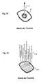
- Figuren 15-16
- Absaugköpfe gemäß dem Stand der Technik zeigen.
Claims (23)
- Vorrichtung (1) zum Absaugen von Flüssigkeit (2) in raumlufttechnischen Anlagen (30) mit einer Absaugpumpe (3), wenigstens einem mit der Absaugpumpe (3) verbundenen Absaugteil zum Ansaugen der Flüssigkeit und Detektionsmitteln (13, 19), die zum Einschalten der Absaugpumpe (3) in Folge einer Detektion der Flüssigkeit (2) eingerichtet sind, dadurch gekennzeichnet, dass jedes Absaugteil ein Absaugkopf (5) ist, der mittels eines Absaugschlauches (4) mit der Absaugpumpe (3) verbunden ist und eine flächige Unterseite (16) aufweist, welche derart gestaltet ist, dass zwischen der abzusaugenden Oberfläche (7) und der Unterseite (16) des Absaugkopfes (5) ein Spalt (17) zum Führen der Flüssigkeit (2) zu den Detektionsmitteln (13, 19) sowie zum Absaugschlauch (4) ausbildbar ist.
- Vorrichtung (1) nach Anspruch 1, dadurch gekennzeichnet, dass durch den Spalt (17) ein Kapillareffekt erzeugbar ist.
- Vorrichtung (1) nach Anspruch 1 oder 2, dadurch gekennzeichnet, dass Einkerbungen (17) in die flächige Unterseite (16) eingebracht sind.
- Vorrichtung (1) nach Anspruch 3, dadurch gekennzeichnet, dass die Einkerbungen (17) Furchen oder Kanäle sind.
- Vorrichtung (1) nach einem der vorhergehenden Ansprüche, dadurch gekennzeichnet, dass die Detektionsmittel (19) an den Absaugköpfen (5) angeordnet sind.
- Vorrichtung (1) nach einem der vorhergehenden Ansprüche, dadurch gekennzeichnet, dass die Detektionsmittel (19) an der Unterseite (16) jedes Absaugkopfes (5) angeordnet sind und zumindest teilweise in den Spalt (17) hinein ragen, wobei ein Entlüftungskanal (22) vorgesehen ist.
- Vorrichtung (1) nach einem der vorhergehenden Ansprüche, dadurch gekennzeichnet, dass die Absaugköpfe (5) so ausgestaltet sind, dass die Durchflussmenge an Flüssigkeit (2) an jedem Absaugkopf (5) derart begrenzt ist, dass an allen Absaugköpfen (5) jeweils eine ausreichende Absaugkraft gewährleistet ist, damit wenigstens an einem Absaugkopf (5) Flüssigkeit (2) einsaugbar ist.
- Vorrichtung (1) nach einem der vorhergehenden Ansprüche, dadurch gekennzeichnet, dass die Absaugköpfe (5) zur Fixierung in der raumlufttechnischen Anlage (30) Magnete (28) und/oder Gewichte (25) aufweisen.
- Vorrichtung (1) nach einem der vorhergehenden Ansprüche, dadurch gekennzeichnet, dass die Absaugköpfe (5) aus einem magnetischen Material gefertigt sind.
- Vorrichtung (1) nach einem der vorhergehenden Ansprüche, dadurch gekennzeichnet, dass die Absaugköpfe (5) aus einem elastischen, sich der Form einer Oberfläche (7) anpassenden Material gefertigt sind.
- Vorrichtung (1) nach einem der vorhergehenden Ansprüche, dadurch gekennzeichnet, dass die Absaugköpfe (5) zur Vermeidung von mikrobiellem Wachstum aus einem antimikrobiell wirksamen oder mikrobiell inerten Werkstoff gefertigt sind.
- Vorrichtung (1) nach einem der vorhergehenden Ansprüche, dadurch gekennzeichnet, dass vor die Absaugpumpe (3) wenigstens ein Feststofffilter (12) geschaltet ist.
- Vorrichtung (1) nach einem der vorhergehenden Ansprüche, dadurch gekennzeichnet, dass die Absaugpumpe (3) nicht trockenlaufsicher ist und vor der Absaugpumpe (3) wenigstens ein Wasserabscheider geschaltet ist.
- Vorrichtung (1) nach einem der vorhergehenden Ansprüche, dadurch gekennzeichnet, dass zwischen den Absaugköpfen (5) und der Absaugpumpe (3) angeordnete Regelventile (11) und eine Steuerungseinheit (9) vorgesehen, wobei die Steuerungseinheit (9) mit den Detektionsmitteln (13, 19) verbunden ist.
- Vorrichtung (1) nach Anspruch 14, dadurch gekennzeichnet, dass die Steuerungseinheit (9) die Regelventile (11) nacheinander öffnet, wobei immer nur ein Regelventil (11) geöffnet ist.
- Vorrichtung (1) nach einem der vorhergehenden Ansprüche, dadurch gekennzeichnet, dass die Absaugschläuche (4) über einen mit einem Desinfektionsregelventil (36) versehenen Zulaufschlauch (35) mit einem Behälter (34) verbunden sind, der mit einer desinfizierenden Flüssigkeit befüllt ist, wobei eine Steuerungseinheit (9) zum Öffnen und Schließen eines Desinfektionsregelventils (36) vorgesehen ist.
- Vorrichtung (1) nach einem der vorhergehenden Ansprüche, dadurch gekennzeichnet, dass die Absaugschläuche (4) über einen mit einem Belüftungsregelventil (40) versehenen Belüftungsschlauch (39) mit dem Auslass eines Belüfters (37) verbunden sind, wobei eine Steuerungseinheit (9) zum Öffnen und Schließen des Belüftungsregelventils (40) und zum Ansteuern des Belüfters (37) vorgesehen ist.
- Vorrichtung (1) nach Anspruch 17, dadurch gekennzeichnet, dass der Belüfter (37) eine Heizeinrichtung (38) aufweist.
- Vorrichtung (1) nach einem der vorhergehenden Ansprüche, dadurch gekennzeichnet, dass die Absaugköpfe (5) über Verbindungsarme (29) miteinander verbunden sind, so dass eine Netzstruktur ausgebildet ist.
- Vorrichtung (1) nach einem der vorhergehenden Ansprüche, dadurch gekennzeichnet, dass die Absaugschläuche (4) unterdruckfest sind.
- Raumlufttechnische Anlage (30) mit einer Vorrichtung (1) nach einem der vorhergehenden Ansprüche, dadurch gekennzeichnet, dass eine von der Vorrichtung (1) abzusaugende Oberfläche (7) mit einer isolierenden Schutzfolie beklebt ist.
- Raumlufttechnische Anlage (30) nach Anspruch 20, dadurch gekennzeichnet, dass die isolierende Schutzfolie Markierungen zum Anordnen der Absaugköpfe (5) aufweist.
- Raumlufttechnische Anlage (30) nach Anspruch 20, dadurch gekennzeichnet, dass die Markierungen ein fluoreszierendes Material enthalten.
Applications Claiming Priority (4)
| Application Number | Priority Date | Filing Date | Title |
|---|---|---|---|
| DE10325204 | 2003-05-28 | ||
| DE10325204 | 2003-05-28 | ||
| DE10327712 | 2003-06-17 | ||
| DE10327712 | 2003-06-17 |
Publications (3)
| Publication Number | Publication Date |
|---|---|
| EP1493982A2 true EP1493982A2 (de) | 2005-01-05 |
| EP1493982A3 EP1493982A3 (de) | 2006-08-09 |
| EP1493982B1 EP1493982B1 (de) | 2007-10-03 |
Family
ID=33435976
Family Applications (1)
| Application Number | Title | Priority Date | Filing Date |
|---|---|---|---|
| EP04090211A Expired - Lifetime EP1493982B1 (de) | 2003-05-28 | 2004-05-27 | Vorrichtungen zum Absaugen von Flüssigkeiten aus raumlufttechnischen Anlagen |
Country Status (3)
| Country | Link |
|---|---|
| EP (1) | EP1493982B1 (de) |
| AT (1) | ATE374914T1 (de) |
| DE (1) | DE502004005111D1 (de) |
Cited By (1)
| Publication number | Priority date | Publication date | Assignee | Title |
|---|---|---|---|---|
| ES2324074A1 (es) * | 2006-11-16 | 2009-07-29 | Ortrud Maria Pech | Dispositivo generador/recuperador de agua aplicable a sistemas y aparatos de aire acondicionado. |
Family Cites Families (3)
| Publication number | Priority date | Publication date | Assignee | Title |
|---|---|---|---|---|
| US3990855A (en) * | 1974-09-20 | 1976-11-09 | Cdc Chemical Corporation | Clog preventing device for air conditioning condensate drain pans |
| GB9201466D0 (en) * | 1992-01-23 | 1992-03-11 | Imi Air Conditioning Ltd | Improvements relating to air conditioners |
| DE19718009A1 (de) * | 1997-04-29 | 1998-11-12 | Stiebel Eltron Gmbh & Co Kg | Raumlüftungsgerät mit einer Kondenswasser-Sammelwanne |
-
2004
- 2004-05-27 EP EP04090211A patent/EP1493982B1/de not_active Expired - Lifetime
- 2004-05-27 DE DE502004005111T patent/DE502004005111D1/de not_active Expired - Lifetime
- 2004-05-27 AT AT04090211T patent/ATE374914T1/de active
Cited By (2)
| Publication number | Priority date | Publication date | Assignee | Title |
|---|---|---|---|---|
| ES2324074A1 (es) * | 2006-11-16 | 2009-07-29 | Ortrud Maria Pech | Dispositivo generador/recuperador de agua aplicable a sistemas y aparatos de aire acondicionado. |
| ES2324074B1 (es) * | 2006-11-16 | 2010-05-13 | Ortrud Maria Pech | Dispositivo generador/recuperador de agua aplicable a sistemas y aparatos de aire acondicionado. |
Also Published As
| Publication number | Publication date |
|---|---|
| EP1493982A3 (de) | 2006-08-09 |
| ATE374914T1 (de) | 2007-10-15 |
| EP1493982B1 (de) | 2007-10-03 |
| DE502004005111D1 (de) | 2007-11-15 |
Similar Documents
| Publication | Publication Date | Title |
|---|---|---|
| DE202009012582U1 (de) | Belüftetes Gestell, besonders für Laborställe, versehen mit Partikelfilter | |
| DE3122509A1 (de) | Brustkorb-drainagevorrichtung | |
| DE69633185T2 (de) | Abwassersystem eines gebäudes | |
| EP1257363A2 (de) | Vorrichtung zum filtern und beseitigen von flüssigkeiten | |
| DE102020112317A1 (de) | Automatisierter Durchlasstest | |
| DE202011001810U1 (de) | Abluftreinigungssystem für Nutztierställe | |
| EP2181583B1 (de) | Verfahren und Vorrichtung zum Be- und Entlüften | |
| DE102009035345A1 (de) | Tiefentnahmegerät für Flüssigkeitsproben | |
| EP1493982A2 (de) | Vorrichtungen zum Absaugen von Flüssigkeiten aus raumlufttechnischen Anlagen | |
| EP2650616A1 (de) | Mobiles mehrteiliges Klimasystem | |
| EP1650169B1 (de) | Biologische Klärvorrichtung mit einer Tauchpumpe | |
| DE202021105121U1 (de) | Mobile Abluftfiltervorrichtung | |
| DE3635013C2 (de) | ||
| DE69728562T2 (de) | Dränagerinne | |
| DE20113965U1 (de) | Anlage zur Reinigung von Abluft, Anlage zur Reinigung von Zuluft, Anlage zur Reinigung von Zu- und Abluft und Anlage zur Reinigung von Umluft in Nutztierställen | |
| DE202017104613U1 (de) | Vorrichtung zur Belüftung und Befeuchtung von Behältern, insbesondere von Unterbringungskäfigen für Versuchstiere | |
| DE19637408A1 (de) | Kondenswasser-Auffangschale für eine Klimaanlage eines Kraftfahrzeuges | |
| DE202020105020U1 (de) | Luftkanalbefeuchter | |
| DE102016117750A1 (de) | Wasserstands-regelungseinrichtung | |
| DE102016101528A1 (de) | Schwimmstoffabzug | |
| DE10041228A1 (de) | Vorrichtung zur Behandlung von Objekten | |
| DE102017127969B3 (de) | Anschlusseinrichtung für eine Absaugvorrichtung | |
| DE202008010151U1 (de) | Belüftungsvorrichtung zur Belüftung eines Absetzbeckens und Absetzbecken mit einer solchen Belüftungsvorrichtung | |
| DE3943704C2 (de) | Vorrichtung zum Absaugen von Abwässern aus Schmutzwassersammelbehälter | |
| EP1792666A2 (de) | Automatisierte Reinigung von offenen Behältern |
Legal Events
| Date | Code | Title | Description |
|---|---|---|---|
| PUAI | Public reference made under article 153(3) epc to a published international application that has entered the european phase |
Free format text: ORIGINAL CODE: 0009012 |
|
| AK | Designated contracting states |
Kind code of ref document: A2 Designated state(s): AT BE BG CH CY CZ DE DK EE ES FI FR GB GR HU IE IT LI LU MC NL PL PT RO SE SI SK TR |
|
| AX | Request for extension of the european patent |
Extension state: AL HR LT LV MK |
|
| PUAL | Search report despatched |
Free format text: ORIGINAL CODE: 0009013 |
|
| AK | Designated contracting states |
Kind code of ref document: A3 Designated state(s): AT BE BG CH CY CZ DE DK EE ES FI FR GB GR HU IE IT LI LU MC NL PL PT RO SE SI SK TR |
|
| AX | Request for extension of the european patent |
Extension state: AL HR LT LV MK |
|
| 17P | Request for examination filed |
Effective date: 20060911 |
|
| GRAP | Despatch of communication of intention to grant a patent |
Free format text: ORIGINAL CODE: EPIDOSNIGR1 |
|
| AKX | Designation fees paid |
Designated state(s): AT BE BG CH CY CZ DE DK EE ES FI FR GB GR HU IE IT LI LU MC NL PL PT RO SE SI SK TR |
|
| GRAS | Grant fee paid |
Free format text: ORIGINAL CODE: EPIDOSNIGR3 |
|
| GRAA | (expected) grant |
Free format text: ORIGINAL CODE: 0009210 |
|
| AK | Designated contracting states |
Kind code of ref document: B1 Designated state(s): AT BE BG CH CY CZ DE DK EE ES FI FR GB GR HU IE IT LI LU MC NL PL PT RO SE SI SK TR |
|
| REG | Reference to a national code |
Ref country code: GB Ref legal event code: FG4D Free format text: NOT ENGLISH |
|
| REG | Reference to a national code |
Ref country code: CH Ref legal event code: EP |
|
| REG | Reference to a national code |
Ref country code: IE Ref legal event code: FG4D Free format text: LANGUAGE OF EP DOCUMENT: GERMAN |
|
| REF | Corresponds to: |
Ref document number: 502004005111 Country of ref document: DE Date of ref document: 20071115 Kind code of ref document: P |
|
| NLV1 | Nl: lapsed or annulled due to failure to fulfill the requirements of art. 29p and 29m of the patents act | ||
| PG25 | Lapsed in a contracting state [announced via postgrant information from national office to epo] |
Ref country code: NL Free format text: LAPSE BECAUSE OF FAILURE TO SUBMIT A TRANSLATION OF THE DESCRIPTION OR TO PAY THE FEE WITHIN THE PRESCRIBED TIME-LIMIT Effective date: 20071003 Ref country code: ES Free format text: LAPSE BECAUSE OF FAILURE TO SUBMIT A TRANSLATION OF THE DESCRIPTION OR TO PAY THE FEE WITHIN THE PRESCRIBED TIME-LIMIT Effective date: 20080114 Ref country code: SE Free format text: LAPSE BECAUSE OF FAILURE TO SUBMIT A TRANSLATION OF THE DESCRIPTION OR TO PAY THE FEE WITHIN THE PRESCRIBED TIME-LIMIT Effective date: 20080103 |
|
| PG25 | Lapsed in a contracting state [announced via postgrant information from national office to epo] |
Ref country code: BG Free format text: LAPSE BECAUSE OF FAILURE TO SUBMIT A TRANSLATION OF THE DESCRIPTION OR TO PAY THE FEE WITHIN THE PRESCRIBED TIME-LIMIT Effective date: 20080103 Ref country code: PL Free format text: LAPSE BECAUSE OF FAILURE TO SUBMIT A TRANSLATION OF THE DESCRIPTION OR TO PAY THE FEE WITHIN THE PRESCRIBED TIME-LIMIT Effective date: 20071003 Ref country code: PT Free format text: LAPSE BECAUSE OF FAILURE TO SUBMIT A TRANSLATION OF THE DESCRIPTION OR TO PAY THE FEE WITHIN THE PRESCRIBED TIME-LIMIT Effective date: 20080303 |
|
| REG | Reference to a national code |
Ref country code: IE Ref legal event code: FD4D |
|
| ET | Fr: translation filed | ||
| PG25 | Lapsed in a contracting state [announced via postgrant information from national office to epo] |
Ref country code: DK Free format text: LAPSE BECAUSE OF FAILURE TO SUBMIT A TRANSLATION OF THE DESCRIPTION OR TO PAY THE FEE WITHIN THE PRESCRIBED TIME-LIMIT Effective date: 20071003 Ref country code: CZ Free format text: LAPSE BECAUSE OF FAILURE TO SUBMIT A TRANSLATION OF THE DESCRIPTION OR TO PAY THE FEE WITHIN THE PRESCRIBED TIME-LIMIT Effective date: 20071003 |
|
| PLBE | No opposition filed within time limit |
Free format text: ORIGINAL CODE: 0009261 |
|
| STAA | Information on the status of an ep patent application or granted ep patent |
Free format text: STATUS: NO OPPOSITION FILED WITHIN TIME LIMIT |
|
| PG25 | Lapsed in a contracting state [announced via postgrant information from national office to epo] |
Ref country code: RO Free format text: LAPSE BECAUSE OF FAILURE TO SUBMIT A TRANSLATION OF THE DESCRIPTION OR TO PAY THE FEE WITHIN THE PRESCRIBED TIME-LIMIT Effective date: 20071003 Ref country code: SK Free format text: LAPSE BECAUSE OF FAILURE TO SUBMIT A TRANSLATION OF THE DESCRIPTION OR TO PAY THE FEE WITHIN THE PRESCRIBED TIME-LIMIT Effective date: 20071003 |
|
| 26N | No opposition filed |
Effective date: 20080704 |
|
| PG25 | Lapsed in a contracting state [announced via postgrant information from national office to epo] |
Ref country code: IE Free format text: LAPSE BECAUSE OF FAILURE TO SUBMIT A TRANSLATION OF THE DESCRIPTION OR TO PAY THE FEE WITHIN THE PRESCRIBED TIME-LIMIT Effective date: 20071003 |
|
| BERE | Be: lapsed |
Owner name: MORITZ, MARTIN, DR.-ING. Effective date: 20080531 Owner name: PETERS, HANS, DR.-ING. Effective date: 20080531 |
|
| PG25 | Lapsed in a contracting state [announced via postgrant information from national office to epo] |
Ref country code: MC Free format text: LAPSE BECAUSE OF NON-PAYMENT OF DUE FEES Effective date: 20080531 |
|
| PG25 | Lapsed in a contracting state [announced via postgrant information from national office to epo] |
Ref country code: GR Free format text: LAPSE BECAUSE OF FAILURE TO SUBMIT A TRANSLATION OF THE DESCRIPTION OR TO PAY THE FEE WITHIN THE PRESCRIBED TIME-LIMIT Effective date: 20080104 |
|
| PG25 | Lapsed in a contracting state [announced via postgrant information from national office to epo] |
Ref country code: BE Free format text: LAPSE BECAUSE OF NON-PAYMENT OF DUE FEES Effective date: 20080531 |
|
| PG25 | Lapsed in a contracting state [announced via postgrant information from national office to epo] |
Ref country code: EE Free format text: LAPSE BECAUSE OF FAILURE TO SUBMIT A TRANSLATION OF THE DESCRIPTION OR TO PAY THE FEE WITHIN THE PRESCRIBED TIME-LIMIT Effective date: 20071003 |
|
| PG25 | Lapsed in a contracting state [announced via postgrant information from national office to epo] |
Ref country code: SI Free format text: LAPSE BECAUSE OF FAILURE TO SUBMIT A TRANSLATION OF THE DESCRIPTION OR TO PAY THE FEE WITHIN THE PRESCRIBED TIME-LIMIT Effective date: 20071003 |
|
| PG25 | Lapsed in a contracting state [announced via postgrant information from national office to epo] |
Ref country code: CY Free format text: LAPSE BECAUSE OF FAILURE TO SUBMIT A TRANSLATION OF THE DESCRIPTION OR TO PAY THE FEE WITHIN THE PRESCRIBED TIME-LIMIT Effective date: 20071003 |
|
| PG25 | Lapsed in a contracting state [announced via postgrant information from national office to epo] |
Ref country code: FI Free format text: LAPSE BECAUSE OF FAILURE TO SUBMIT A TRANSLATION OF THE DESCRIPTION OR TO PAY THE FEE WITHIN THE PRESCRIBED TIME-LIMIT Effective date: 20071003 |
|
| PG25 | Lapsed in a contracting state [announced via postgrant information from national office to epo] |
Ref country code: LU Free format text: LAPSE BECAUSE OF NON-PAYMENT OF DUE FEES Effective date: 20080527 Ref country code: HU Free format text: LAPSE BECAUSE OF FAILURE TO SUBMIT A TRANSLATION OF THE DESCRIPTION OR TO PAY THE FEE WITHIN THE PRESCRIBED TIME-LIMIT Effective date: 20080404 |
|
| PG25 | Lapsed in a contracting state [announced via postgrant information from national office to epo] |
Ref country code: TR Free format text: LAPSE BECAUSE OF FAILURE TO SUBMIT A TRANSLATION OF THE DESCRIPTION OR TO PAY THE FEE WITHIN THE PRESCRIBED TIME-LIMIT Effective date: 20071003 |
|
| PG25 | Lapsed in a contracting state [announced via postgrant information from national office to epo] |
Ref country code: IT Free format text: LAPSE BECAUSE OF NON-PAYMENT OF DUE FEES Effective date: 20080531 |
|
| PGFP | Annual fee paid to national office [announced via postgrant information from national office to epo] |
Ref country code: AT Payment date: 20110517 Year of fee payment: 8 |
|
| REG | Reference to a national code |
Ref country code: AT Ref legal event code: MM01 Ref document number: 374914 Country of ref document: AT Kind code of ref document: T Effective date: 20120527 |
|
| PG25 | Lapsed in a contracting state [announced via postgrant information from national office to epo] |
Ref country code: AT Free format text: LAPSE BECAUSE OF NON-PAYMENT OF DUE FEES Effective date: 20120527 |
|
| PGFP | Annual fee paid to national office [announced via postgrant information from national office to epo] |
Ref country code: GB Payment date: 20140519 Year of fee payment: 11 |
|
| PGFP | Annual fee paid to national office [announced via postgrant information from national office to epo] |
Ref country code: CH Payment date: 20140522 Year of fee payment: 11 |
|
| PGFP | Annual fee paid to national office [announced via postgrant information from national office to epo] |
Ref country code: FR Payment date: 20140520 Year of fee payment: 11 |
|
| REG | Reference to a national code |
Ref country code: CH Ref legal event code: PL |
|
| GBPC | Gb: european patent ceased through non-payment of renewal fee |
Effective date: 20150527 |
|
| PG25 | Lapsed in a contracting state [announced via postgrant information from national office to epo] |
Ref country code: LI Free format text: LAPSE BECAUSE OF NON-PAYMENT OF DUE FEES Effective date: 20150531 Ref country code: CH Free format text: LAPSE BECAUSE OF NON-PAYMENT OF DUE FEES Effective date: 20150531 |
|
| REG | Reference to a national code |
Ref country code: FR Ref legal event code: ST Effective date: 20160129 |
|
| PG25 | Lapsed in a contracting state [announced via postgrant information from national office to epo] |
Ref country code: GB Free format text: LAPSE BECAUSE OF NON-PAYMENT OF DUE FEES Effective date: 20150527 |
|
| PG25 | Lapsed in a contracting state [announced via postgrant information from national office to epo] |
Ref country code: FR Free format text: LAPSE BECAUSE OF NON-PAYMENT OF DUE FEES Effective date: 20150601 |
|
| PGFP | Annual fee paid to national office [announced via postgrant information from national office to epo] |
Ref country code: DE Payment date: 20170421 Year of fee payment: 14 |
|
| REG | Reference to a national code |
Ref country code: DE Ref legal event code: R119 Ref document number: 502004005111 Country of ref document: DE |
|
| PG25 | Lapsed in a contracting state [announced via postgrant information from national office to epo] |
Ref country code: DE Free format text: LAPSE BECAUSE OF NON-PAYMENT OF DUE FEES Effective date: 20181201 |