EP1493981B1 - Système diagnostique pour compresseur - Google Patents
Système diagnostique pour compresseur Download PDFInfo
- Publication number
- EP1493981B1 EP1493981B1 EP04023650A EP04023650A EP1493981B1 EP 1493981 B1 EP1493981 B1 EP 1493981B1 EP 04023650 A EP04023650 A EP 04023650A EP 04023650 A EP04023650 A EP 04023650A EP 1493981 B1 EP1493981 B1 EP 1493981B1
- Authority
- EP
- European Patent Office
- Prior art keywords
- compressor
- logic circuitry
- sensor
- protector
- motor
- Prior art date
- Legal status (The legal status is an assumption and is not a legal conclusion. Google has not performed a legal analysis and makes no representation as to the accuracy of the status listed.)
- Expired - Lifetime
Links
Images


Classifications
-
- F—MECHANICAL ENGINEERING; LIGHTING; HEATING; WEAPONS; BLASTING
- F04—POSITIVE - DISPLACEMENT MACHINES FOR LIQUIDS; PUMPS FOR LIQUIDS OR ELASTIC FLUIDS
- F04C—ROTARY-PISTON, OR OSCILLATING-PISTON, POSITIVE-DISPLACEMENT MACHINES FOR LIQUIDS; ROTARY-PISTON, OR OSCILLATING-PISTON, POSITIVE-DISPLACEMENT PUMPS
- F04C28/00—Control of, monitoring of, or safety arrangements for, pumps or pumping installations specially adapted for elastic fluids
- F04C28/28—Safety arrangements; Monitoring
-
- F—MECHANICAL ENGINEERING; LIGHTING; HEATING; WEAPONS; BLASTING
- F04—POSITIVE - DISPLACEMENT MACHINES FOR LIQUIDS; PUMPS FOR LIQUIDS OR ELASTIC FLUIDS
- F04B—POSITIVE-DISPLACEMENT MACHINES FOR LIQUIDS; PUMPS
- F04B51/00—Testing machines, pumps, or pumping installations
-
- B—PERFORMING OPERATIONS; TRANSPORTING
- B25—HAND TOOLS; PORTABLE POWER-DRIVEN TOOLS; MANIPULATORS
- B25J—MANIPULATORS; CHAMBERS PROVIDED WITH MANIPULATION DEVICES
- B25J9/00—Programme-controlled manipulators
- B25J9/16—Programme controls
- B25J9/1679—Programme controls characterised by the tasks executed
- B25J9/1687—Assembly, peg and hole, palletising, straight line, weaving pattern movement
-
- F—MECHANICAL ENGINEERING; LIGHTING; HEATING; WEAPONS; BLASTING
- F04—POSITIVE - DISPLACEMENT MACHINES FOR LIQUIDS; PUMPS FOR LIQUIDS OR ELASTIC FLUIDS
- F04C—ROTARY-PISTON, OR OSCILLATING-PISTON, POSITIVE-DISPLACEMENT MACHINES FOR LIQUIDS; ROTARY-PISTON, OR OSCILLATING-PISTON, POSITIVE-DISPLACEMENT PUMPS
- F04C18/00—Rotary-piston pumps specially adapted for elastic fluids
- F04C18/02—Rotary-piston pumps specially adapted for elastic fluids of arcuate-engagement type, i.e. with circular translatory movement of co-operating members, each member having the same number of teeth or tooth-equivalents
- F04C18/0207—Rotary-piston pumps specially adapted for elastic fluids of arcuate-engagement type, i.e. with circular translatory movement of co-operating members, each member having the same number of teeth or tooth-equivalents both members having co-operating elements in spiral form
- F04C18/0215—Rotary-piston pumps specially adapted for elastic fluids of arcuate-engagement type, i.e. with circular translatory movement of co-operating members, each member having the same number of teeth or tooth-equivalents both members having co-operating elements in spiral form where only one member is moving
-
- F—MECHANICAL ENGINEERING; LIGHTING; HEATING; WEAPONS; BLASTING
- F04—POSITIVE - DISPLACEMENT MACHINES FOR LIQUIDS; PUMPS FOR LIQUIDS OR ELASTIC FLUIDS
- F04C—ROTARY-PISTON, OR OSCILLATING-PISTON, POSITIVE-DISPLACEMENT MACHINES FOR LIQUIDS; ROTARY-PISTON, OR OSCILLATING-PISTON, POSITIVE-DISPLACEMENT PUMPS
- F04C28/00—Control of, monitoring of, or safety arrangements for, pumps or pumping installations specially adapted for elastic fluids
- F04C28/06—Control of, monitoring of, or safety arrangements for, pumps or pumping installations specially adapted for elastic fluids specially adapted for stopping, starting, idling or no-load operation
-
- F—MECHANICAL ENGINEERING; LIGHTING; HEATING; WEAPONS; BLASTING
- F04—POSITIVE - DISPLACEMENT MACHINES FOR LIQUIDS; PUMPS FOR LIQUIDS OR ELASTIC FLUIDS
- F04C—ROTARY-PISTON, OR OSCILLATING-PISTON, POSITIVE-DISPLACEMENT MACHINES FOR LIQUIDS; ROTARY-PISTON, OR OSCILLATING-PISTON, POSITIVE-DISPLACEMENT PUMPS
- F04C29/00—Component parts, details or accessories of pumps or pumping installations, not provided for in groups F04C18/00 - F04C28/00
- F04C29/0042—Driving elements, brakes, couplings, transmissions specially adapted for pumps
- F04C29/0085—Prime movers
-
- F—MECHANICAL ENGINEERING; LIGHTING; HEATING; WEAPONS; BLASTING
- F25—REFRIGERATION OR COOLING; COMBINED HEATING AND REFRIGERATION SYSTEMS; HEAT PUMP SYSTEMS; MANUFACTURE OR STORAGE OF ICE; LIQUEFACTION SOLIDIFICATION OF GASES
- F25B—REFRIGERATION MACHINES, PLANTS OR SYSTEMS; COMBINED HEATING AND REFRIGERATION SYSTEMS; HEAT PUMP SYSTEMS
- F25B49/00—Arrangement or mounting of control or safety devices
- F25B49/005—Arrangement or mounting of control or safety devices of safety devices
-
- F—MECHANICAL ENGINEERING; LIGHTING; HEATING; WEAPONS; BLASTING
- F25—REFRIGERATION OR COOLING; COMBINED HEATING AND REFRIGERATION SYSTEMS; HEAT PUMP SYSTEMS; MANUFACTURE OR STORAGE OF ICE; LIQUEFACTION SOLIDIFICATION OF GASES
- F25B—REFRIGERATION MACHINES, PLANTS OR SYSTEMS; COMBINED HEATING AND REFRIGERATION SYSTEMS; HEAT PUMP SYSTEMS
- F25B49/00—Arrangement or mounting of control or safety devices
- F25B49/02—Arrangement or mounting of control or safety devices for compression type machines, plants or systems
- F25B49/025—Motor control arrangements
-
- F—MECHANICAL ENGINEERING; LIGHTING; HEATING; WEAPONS; BLASTING
- F04—POSITIVE - DISPLACEMENT MACHINES FOR LIQUIDS; PUMPS FOR LIQUIDS OR ELASTIC FLUIDS
- F04C—ROTARY-PISTON, OR OSCILLATING-PISTON, POSITIVE-DISPLACEMENT MACHINES FOR LIQUIDS; ROTARY-PISTON, OR OSCILLATING-PISTON, POSITIVE-DISPLACEMENT PUMPS
- F04C2270/00—Control; Monitoring or safety arrangements
- F04C2270/07—Electric current
-
- F—MECHANICAL ENGINEERING; LIGHTING; HEATING; WEAPONS; BLASTING
- F04—POSITIVE - DISPLACEMENT MACHINES FOR LIQUIDS; PUMPS FOR LIQUIDS OR ELASTIC FLUIDS
- F04C—ROTARY-PISTON, OR OSCILLATING-PISTON, POSITIVE-DISPLACEMENT MACHINES FOR LIQUIDS; ROTARY-PISTON, OR OSCILLATING-PISTON, POSITIVE-DISPLACEMENT PUMPS
- F04C2270/00—Control; Monitoring or safety arrangements
- F04C2270/78—Warnings
- F04C2270/784—Light
-
- F—MECHANICAL ENGINEERING; LIGHTING; HEATING; WEAPONS; BLASTING
- F04—POSITIVE - DISPLACEMENT MACHINES FOR LIQUIDS; PUMPS FOR LIQUIDS OR ELASTIC FLUIDS
- F04C—ROTARY-PISTON, OR OSCILLATING-PISTON, POSITIVE-DISPLACEMENT MACHINES FOR LIQUIDS; ROTARY-PISTON, OR OSCILLATING-PISTON, POSITIVE-DISPLACEMENT PUMPS
- F04C2270/00—Control; Monitoring or safety arrangements
- F04C2270/80—Diagnostics
-
- F—MECHANICAL ENGINEERING; LIGHTING; HEATING; WEAPONS; BLASTING
- F04—POSITIVE - DISPLACEMENT MACHINES FOR LIQUIDS; PUMPS FOR LIQUIDS OR ELASTIC FLUIDS
- F04C—ROTARY-PISTON, OR OSCILLATING-PISTON, POSITIVE-DISPLACEMENT MACHINES FOR LIQUIDS; ROTARY-PISTON, OR OSCILLATING-PISTON, POSITIVE-DISPLACEMENT PUMPS
- F04C2270/00—Control; Monitoring or safety arrangements
- F04C2270/86—Detection
-
- F—MECHANICAL ENGINEERING; LIGHTING; HEATING; WEAPONS; BLASTING
- F04—POSITIVE - DISPLACEMENT MACHINES FOR LIQUIDS; PUMPS FOR LIQUIDS OR ELASTIC FLUIDS
- F04C—ROTARY-PISTON, OR OSCILLATING-PISTON, POSITIVE-DISPLACEMENT MACHINES FOR LIQUIDS; ROTARY-PISTON, OR OSCILLATING-PISTON, POSITIVE-DISPLACEMENT PUMPS
- F04C2270/00—Control; Monitoring or safety arrangements
- F04C2270/90—Remote control, e.g. wireless, via LAN, by radio, or by a wired connection from a central computer
-
- F—MECHANICAL ENGINEERING; LIGHTING; HEATING; WEAPONS; BLASTING
- F04—POSITIVE - DISPLACEMENT MACHINES FOR LIQUIDS; PUMPS FOR LIQUIDS OR ELASTIC FLUIDS
- F04C—ROTARY-PISTON, OR OSCILLATING-PISTON, POSITIVE-DISPLACEMENT MACHINES FOR LIQUIDS; ROTARY-PISTON, OR OSCILLATING-PISTON, POSITIVE-DISPLACEMENT PUMPS
- F04C23/00—Combinations of two or more pumps, each being of rotary-piston or oscillating-piston type, specially adapted for elastic fluids; Pumping installations specially adapted for elastic fluids; Multi-stage pumps specially adapted for elastic fluids
- F04C23/008—Hermetic pumps
-
- F—MECHANICAL ENGINEERING; LIGHTING; HEATING; WEAPONS; BLASTING
- F25—REFRIGERATION OR COOLING; COMBINED HEATING AND REFRIGERATION SYSTEMS; HEAT PUMP SYSTEMS; MANUFACTURE OR STORAGE OF ICE; LIQUEFACTION SOLIDIFICATION OF GASES
- F25B—REFRIGERATION MACHINES, PLANTS OR SYSTEMS; COMBINED HEATING AND REFRIGERATION SYSTEMS; HEAT PUMP SYSTEMS
- F25B2700/00—Sensing or detecting of parameters; Sensors therefor
- F25B2700/15—Power, e.g. by voltage or current
- F25B2700/151—Power, e.g. by voltage or current of the compressor motor
-
- F—MECHANICAL ENGINEERING; LIGHTING; HEATING; WEAPONS; BLASTING
- F25—REFRIGERATION OR COOLING; COMBINED HEATING AND REFRIGERATION SYSTEMS; HEAT PUMP SYSTEMS; MANUFACTURE OR STORAGE OF ICE; LIQUEFACTION SOLIDIFICATION OF GASES
- F25B—REFRIGERATION MACHINES, PLANTS OR SYSTEMS; COMBINED HEATING AND REFRIGERATION SYSTEMS; HEAT PUMP SYSTEMS
- F25B2700/00—Sensing or detecting of parameters; Sensors therefor
- F25B2700/19—Pressures
- F25B2700/193—Pressures of the compressor
- F25B2700/1931—Discharge pressures
-
- F—MECHANICAL ENGINEERING; LIGHTING; HEATING; WEAPONS; BLASTING
- F25—REFRIGERATION OR COOLING; COMBINED HEATING AND REFRIGERATION SYSTEMS; HEAT PUMP SYSTEMS; MANUFACTURE OR STORAGE OF ICE; LIQUEFACTION SOLIDIFICATION OF GASES
- F25B—REFRIGERATION MACHINES, PLANTS OR SYSTEMS; COMBINED HEATING AND REFRIGERATION SYSTEMS; HEAT PUMP SYSTEMS
- F25B2700/00—Sensing or detecting of parameters; Sensors therefor
- F25B2700/21—Temperatures
- F25B2700/2106—Temperatures of fresh outdoor air
-
- F—MECHANICAL ENGINEERING; LIGHTING; HEATING; WEAPONS; BLASTING
- F25—REFRIGERATION OR COOLING; COMBINED HEATING AND REFRIGERATION SYSTEMS; HEAT PUMP SYSTEMS; MANUFACTURE OR STORAGE OF ICE; LIQUEFACTION SOLIDIFICATION OF GASES
- F25B—REFRIGERATION MACHINES, PLANTS OR SYSTEMS; COMBINED HEATING AND REFRIGERATION SYSTEMS; HEAT PUMP SYSTEMS
- F25B2700/00—Sensing or detecting of parameters; Sensors therefor
- F25B2700/21—Temperatures
- F25B2700/2116—Temperatures of a condenser
Definitions
- the present invention relates to a diagnostic system for a refrigeration or air-conditioning system. More particularly, the present invention relates to a diagnostic system for a refrigeration or air-conditioning system which uses various operating characteristics and the compressor's "trip" information to diagnose the problems associated with the refrigeration or air-conditioning system.
- a class of machines exists in the art generally known as scroll machines which are used for the displacement of various types of fluid. These scroll machines can be configured as an expander, a displacement engine, a pump, a compressor, etc. and the features of the present invention are applicable to any of these machines. For purposes of illustration, however, the disclosed embodiment is in the form of a hermetic refrigerant scroll compressor used within a refrigeration or air conditioning system.
- Scroll compressors are becoming more and more popular for use as compressors in both refrigeration as well as air conditioning applications due primarily to their capability for extremely efficient operation.
- these machines incorporate a pair of intermeshed spiral wraps, one of which is caused to orbit relative to the other so as to define one or more moving chambers which progressively decrease in size as they travel from an outer suction port toward a center discharge port.
- An electric motor is provided which operates to drive the orbiting scroll member via a suitable drive shaft affixed to the motor rotor.
- the bottom of the hermetic shell normally contains an oil sump for lubricating and cooling purposes. While the diagnostic system of the present invention will be described in conjunction with a scroll compressor, it is to be understood that the diagnostic system of the present invention can be used with other types of compressors also.
- the present invention discloses a device that increases the accuracy of the problem diagnosis for an air conditioning or refrigeration system.
- inter line break protectors are thermally sensitive devices which are wired in electrical series with the motor.
- the protectors react thermally to the line current drawn by the motor and also other temperatures within the compressor including but not limited to discharge gas temperature, suction gas temperature or temperature of a particular component in the compressor.
- discharge gas temperature e.g., suction gas temperature
- temperature of a particular component in the compressor e.g., suction gas temperature
- the protector will open the electrical connection to the motor. This shuts down the motor operating the compressor which in turn shuts down the compressor and prevents it from operating in regions that would lead to its failure. After a period of time, when the temperatures have fallen to safe levels, the protector automatically resets itself and the compressor operates again.
- the temperatures that the protector is reacting to are a result of the operation of the compressor and the entire refrigeration or air-conditioning system. Either the operation of the compressor or the operation of the entire system can influence the temperatures sensed by these protectors.
- the significant aspect of the protection system is that some categories of faults repeatedly trip the protector with very short compressor ON time and other categories of faults trip the protector less frequently thus providing relatively longer compressor ON times. For example, a compressor with seized bearings would trip the protector within about twenty seconds or less of ON time.
- a system that has a very low refrigerant charge will trip the protector after typically more than ninety minutes of ON time. An analysis of the trip frequency, trip reset times and compressor ON times will provide valuable clues in identifying the cause of the system's problems.
- the present invention provides a device which is based on this principle and is defined in claim 1.
- the device of the preferred embodiment continuously records the status of the protector (open or closed) as a function of time and then it analyzes this status information to determine a faulty situation.
- the device goes further and isolates the fault to either the compressor or to the rest of the system. Once the fault has been isolated, the device will activate a visual indicator (light) and it will also send an electrical signal to any intelligent device (controller, computer, etc.) advising about the situation.
- the technician on arriving at the scene, then has a clear indication that the problem is most likely in the system components other than the compressor or the problem is most likely in the compressor. He can then focus his further trouble shooting to the identified area.
- the device thus avoids the previously described situation of a confused diagnosis and the potential of mistakenly replacing a good compressor.
- additional information can be gathered by sensors that monitor other operating characteristics of the refrigeration system such as supply voltage and outdoor ambient temperature. This additional information can then be used to further diagnose the problems associated with the refrigeration or air-conditioning system.
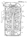
- Figure 1 is a vertical cross section of a hermetic scroll compressor incorporating the unique compressor diagnostic system in accordance with the present invention
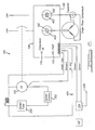
- Figure 2 is a schematic representation of the diagnostic system for a single phase motor for the compressor in accordance with the present invention
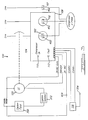
- Figure 3 is a schematic representation of a diagnostic system for a three phase motor for the compressor in accordance with another embodiment of the present invention.
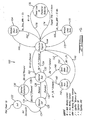
- Figure 4 is a flow diagram of the diagnostic system for the single phase motor for the compressor in accordance with the present invention.
- Figure 5 is a flow diagram of the diagnostic system for the three phase motor for the compressor in accordance with the present invention.
- Figure 6 is a flow diagram which is followed when diagnosing a compressor system
- Figure 7 is a schematic view of a typical refrigeration system utilizing the compressor and diagnostic system in accordance with the present invention.
- Figure 8 is a perspective view of a contactor integrated with the diagnostic system's circuitry in accordance with another embodiment of the present invention.
- Figure 9 is a schematic view illustrating the circuitry of the contactor illustrated in Figure 8 ;
- Figure 10 is a schematic view of a compressor plug which illustrates the diagnostic system's circuitry in accordance with another embodiment of the present invention.
- Figure 11 is a flow diagram of a diagnostic system for the compressor in accordance with another embodiment of the present invention.
- Figure 12 is a chart indicating the possible system faults based upon ON time before trips
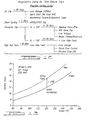
- Figure 13 is a graph showing electrical current versus the temperature of the condenser
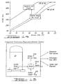
- Figure 14 is a graph showing percent run time versus outdoor ambient temperature.
- Figure 15 is a schematic illustration of a diagnostic system in accordance with the present invention.
- FIG. 1 a scroll compressor incorporating the unique compressor diagnostic system in accordance with the present invention and which is designated generally by the reference numeral 10. While compressor 10 is being illustrated as a scroll compressor in conjunction with a refrigeration or air conditioning system, it is within the scope of the present invention to utilize other types of compressors in the refrigeration or air conditioning system if desired as well as having any of the compressor designs being in conjunction with other types of systems.
- Scroll compressor 10 comprises a generally cylindrical hermetic shell 12 having welded at the upper end thereof a cap 14 and at the lower end thereof a base 16 having a plurality of mounting feet (not shown) integrally formed therewith.
- Cap 14 is provided with a refrigerant discharge fitting 18 which may have the usual discharge valve therein.
- a transversely extending partition 20 is affixed to shell 12 by being welded about is periphery at the same point that cap 14 is welded to shell 12.
- a compressor mounting frame 22 is press fit within shell 12 and it is supported by the end of base 16.
- Base 16 is slightly smaller in diameter than shell 12 such that base 16 is received within shell 12 and welded about its periphery as shown in Figure 1 .
- compressor 10 Major elements of compressor 10 that are affixed to frame 22 include a two-piece main bearing housing assembly 24, a lower bearing housing 26 and a motor stator 28.
- Crankshaft 30 has at the lower end thereof a relatively large diameter concentric bore 38 which communicates with a radially outwardly positioned smaller diameter bore 40 extending upwardly therefrom to the top of crankshaft 30.
- the lower portion of the interior of shell 12 defines an oil sump 44 which is filled with lubricating oil to a level slightly above the lower end of a rotor, and bore 38 acts as a pump to pump lubricating fluid up crankshaft 30 and into bore 40 and ultimately to all of the various portions of compressor 10 which require lubrication.
- Crankshaft 30 is rotatably driven by an electric motor which includes stator 28, windings 46 passing therethrough and a rotor 48 press fitted into crankshaft 30.
- An upper counterweight 50 is secured to crankshaft 30 and a lower counterweight 52 is secured to rotor 48.
- a temperature protector 54 of the usual type; is provided in close proximity to motor windings 46. Temperature protector 54 will de-energize the motor if thermal protector 54 exceeds its normal temperature range. Temperature protector 54 can be heated by motor windings 46, suction gas within a suction chamber 56 and/or discharge gas within a discharge chamber 58 which is released into suction chamber 56. Both suction chamber 56 and discharge chamber 58 are defined by shell 12, cap 14, base 16 and partition 22 as shown in Figure 1 .
- the upper surface of two-piece main bearing housing assembly 24 is provided with a flat thrust bearing surface on which is disposed an orbiting scroll member 60 having the usual spiral vane or wrap 62 extending upward from an end plate 64.
- an orbiting scroll member 60 Projecting downwardly from the lower surface of end plate 64 of orbiting scroll member 60 is a cylindrical hub 66 having a journal bearing therein and which is rotatably disposed a drive bushing 68 having an inner bore in which crank pin 32 is drivingly disposed.
- Crank pin 32 has a flat on one surface which drivingly engages a flat surface formed in a portion of the inner bore of drive bushing 68 to provide a radially compliant driving arrangement, such as shown in Assignee's U.S. Letters Patent 4,877,382 .
- Oldham coupling 70 is also provided positioned between orbiting scroll member 60 and two-piece bearing housing assembly 24. Oldham coupling 70 is keyed to orbiting scroll member 60 and to a non-orbiting scroll member 72 to prevent rotational movement of orbiting scroll member 60.
- Non-orbiting scroll member 72 is also provided with a wrap 74 extending downwardly from an end plate 76 which is positioned in meshing engagement with wrap 62 of orbiting scroll member 60.
- Non-orbiting scroll member 72 has a centrally disposed discharge passage 78 which communicates with an upwardly open recess 80 which is in turn in communication with discharge chamber 58.
- An annular recess 82 is also formed in non-orbiting scroll member 72 within which is disposed a floating seal assembly 84.
- Recesses 80 and 82 and floating seal assembly 84 cooperate to define axial pressure biasing chambers which receive pressurized fluid being compressed by wraps 62 and 74 so as to exert an axial biasing force on non-orbiting scroll member 72 to thereby urge the tips of respective wraps 62 and 74 into sealing engagement with the opposed end surfaces of end plates 76 and 64, respectively.
- Floating seal assembly is preferably of the type described in greater detail in Assignee's U.S. Letters Patent 5,156,639 .
- Non-orbiting scroll member 72 is designed to be mounted for limited axial movement with respect to two-piece main bearing housing assembly 24 in a suitable manner such as disclosed in the aforementioned U.S. Letters Patent 4,877,382 or Assignee's U.S. Letters Patent 5,102,316 .
- Compressor 10 is powered by electricity which is provided to the electric motor within shell 12 through a molded electric plug 90.
- Diagnostic system 100 comprises one or more current sensing devices 102 and the associated logic circuitry 104.
- Current sensing devices 102 are mounted in a housing 106 mounted externally to shell 12.
- Logic circuitry 104 can be mounted in housing 106 or it can be located in a convenient position with respect to compressor 10 as shown in phantom in Figure 2 .
- the sensing device and circuitry can be integrated into a special contactor, a special wiring harness or into a molded plug utilized for some compressor designs.
- Current sensing devices 102 sense the current in the power supply wires powering compressor 10.
- Figure 2 illustrates two current sensing devices 102 in conjunction with a single-phase motor. One of the current sensing devices 102 is associated with the main windings for the compressor motor and the other current sensing device 102 is associated with the auxiliary windings for the compressor motor.
- Figure 3 also illustrates two current sensing devices 102 in conjunction with a three phase motor. Each current sensing device 102 is associated.with one of the phases of the three phase power supply.
- Figure 3 illustrates two current sensing devices sensing current in two phases of the three phase power supply
- a third current sensor 102 to sense the current in the third phase of the three phase power supply as shown in phantom in Figure 3 if desired.
- These current signals represent an indication of the status of protector 54 (open or closed).
- current sensing devices 102 sense the status of protector 54 utilizing the current in the power supply wires, it is also possible to sense the status of protector 54 by sensing the presence or absence of voltage on the motor side of protector 54.
- the inventors of the present invention consider this to be a less desirable but effective approach in some cases because it requires an additional hermetic feed-through pin extending through shell 12.
- the demand signal for compressor 10 is acquired by sensing the presence of supply voltage or by having a system controller (not shown) supply a discrete signal representing the demand.
- the demand signal and the signal received by logic circuitry 104 are processed by logic circuitry 104 to derive the information about the trip frequency of protector 54 and the average ON time and OFF time of compressor 10.
- Logic circuitry 104 analyses the combination of current signals, the demand signal and the derived protector trip frequencies to determine if a fault condition exists.
- Logic circuitry also has the unique capability of identifying a specific cause based on some faults. This information is provided to the service people using a green LED light 110 and a yellow LED light 112. Green LED light 110 is utilized to indicate that there is (currently no fault condition and that the system is functioning normally.
- Yellow LED light 112 is utilized to indicate the presence of a fault. When yellow LED light 112 is turned ON, green LED light 110 is turned OFF. Thus, yellow LED light 112 is utilized to visually communicate that there is a fault as well as indicating the type of fault that is present. This communication is accomplished by tuming yellow LED light 112 ON and then OFF for a specific duration and sequence to indicate both that there is a fault and to identify what the fault is: For example, turning light 112 ON for one second and turning it OFF for nineteen seconds and repeating this sequence every twenty seconds will create the effect of a blinking light that blinks ON once every twenty seconds. This sequence corresponds to a type of fault that is coded as a type 1 fault.
- logic circuitry 104 In addition to visually communicating the specific fault code using light 112, logic circuitry 104 also outputs a coded sequence of electrical pulses to other intelligent controllers that may exist in the system. These coded pulses represent the type of fault that has been detected by diagnostic system 100. The types of faults which can be detected by logic circuitry 104 include, but are not limited to:
- diagnostic system 100 may only send the status of protector 54 to an intelligent device 116.
- the parameters of trip frequencies, ON times and OFF times with the diagnosis information may be generated at intelligent device 116.
- Intelligent device 116 can be a compressor controller associated with compressor 10, it can be a system controller monitoring a plurality of compressors 10, it can be a remotely located device or it can be any other device which is selected to monitor diagnostic system 100 of one or more compressors.
- Figure 4 represents a flow diagram for diagnostic system 100 in conjunction with a single phase compressor.
- the demand signal is provided to logic circuitry 104 from a device or a contactor 120 ( Figures 2 and 3 ) along with the current signal from sensing devices 102.
- an initializing process is performed at 122 and, if successful, the system, as shown by arrow 124, goes to a normal OFF condition as shown at 126.
- the system moves as shown by arrow 128 to a normal run condition shown at 130. Once the demand has been met, the system returns to the normal OFF condition 126 as shown by arrow 132.
- the system moves to the protector tripped condition 144 as shown by arrow 152 when both a main winding current and an auxiliary winding current are not sensed.
- the system moves as shown by arrow 154 to the protector tripped condition 144.
- While operating in the protector tripped condition 144 one of four paths can be followed. First, if main winding current or auxiliary winding current is sensed and the demand is satisfied, the system moves as shown by arrow 160 to the normal run condition 130. Second, with the protector tripped, and the moving window average of the ON time of the system has been less than twelve seconds, the system moves as shown by arrow 162 to a multiple short run condition 164. From the multiple short run condition, the system moves back to the protector tripped condition 144 as shown by arrow 166. Third, with the protector tripped, and the moving window average of the ON time of the system has been greater than fifteen minutes, the system moves as shown by arrow 168 to a multiple long run condition 170.
- the system moves back to the protector tripped condition 144 as shown by arrow 172.
- the protector tripped if the tripped time exceeds four hours, the system moves as shown by arrow 174 to a power loss or protector defective condition 176. If, while the system is in the power loss or protector defective condition 176 and main winding current or auxiliary winding current is sensed, the system moves back to the protector tripped condition 144 as shown by arrow 178.
- the blinking of light 112 is dictated by the fault condition sensed.
- a protector tripped condition is sensed at 154 because demand is present but current is missing, light 112 blinks once.
- compressor 10 is seized or there is a low supply voltage problem such as indicated by arrow 162 because the average ON time during the last five trips was less than twelve seconds, light 112 blinks twice.
- the protector is faulty or the contactor is faulty as indicated by arrow 174 because the OFF time is greater than four hours, light 112 blinks three times.
- auxiliary windings are open or there is a faulty run capacitor as indicated by arrow 140, light 112 blinks four times. If the main winding is open as indicated by arrow 148, light 112 blinks five times. If the contactor is welded as indicated by arrow 134 because current is sensed but there is no demand, light 112 blinks six times. Finally, if there are repeated protector trips due to other system problems as indicated by arrow 168 because the average ON time during the last five trips was less than fifteen minutes, light 112 blinks seven times.
- Figure 5 represents a flow diagram for diagnostic system 100 in conjunction with a three phase compressor.
- the demand signal is provided to logic circuitry 104 from contactor 120 ( Figures 2 and 3 ) along with the current signal from sensing devices 102.
- an initializing process is performed at 122 and, if successful, the system, as shown by arrow 124, goes to a normal OFF condition as shown at 126.
- the system moves as shown by arrow 128 to a normal run condition shown at 130. Once the demand has been met, the system returns to the normal OFF condition 126 as shown by arrow 132.
- the system senses demand and eleven milliseconds is less than the zero crossing time difference between the first and second phases of the three phase power supply or this time difference is less than fourteen milliseconds, the system moves as shown by arrow 240 to a phase sequence reversed condition 242. From here, the system moves to a protector tripped condition 144 as shown by arrow 246 when both a first phase current or a second phase current is not sensed.
- the system moves as shown by arrow 248 to a phase missing condition 250. From here, the system moves to the protector tripped condition 144 as shown by arrow 252 when both a first phase current and a second phase current are not sensed.
- the system moves as shown by arrow 254 to the protector tripped condition 144.
- While operating in the protector tripped condition 144 one of four paths can be followed. First, if first phase current or second phase current is sensed and the demand is satisfied, the system moves as shown by arrow 260 to the normal run condition 130. Second, with the protector tripped, and the moving window average of the ON time of the system has been less than twelve seconds, the system moves as shown by arrow 162 to a multiple short run condition 164. From the multiple short run condition, the system moves back to the protector tripped condition 144 as shown by arrow 166. Third, with the protector tripped, and the moving window average of the ON time of the system has been greater than fifteen minutes, the system moves as shown by arrow 168 to a multiple long run condition 170.
- the system moves back to the protector tripped condition 144 as shown by arrow 172.
- Fourth, with the protector tripped if the tripped time exceeds four hours, the system moves as shown by arrow 174 to a power loss or protector defective condition 176. If, while the system is in the power loss or protector defective condition 176 and first phase current or second phase current is sensed, the system moves back to the protector tripped condition 144 as shown by arrow 278.
- the blinking of light 112 is dictated by the fault condition sensed.
- a protector tripped condition is sensed at 254 because demand is present but current is missing, light 112 blinks once.
- compressor 10 is seized or there is a low supply voltage problem such as indicated by arrow 162 because the average ON time during the last five trips was less than twelve seconds, light 112 blinks twice.
- the protector is faulty or the contactor is faulty as indicated by arrow 174 because the OFF time is greater than four hours, light 112 blinks three times.
- logic circuitry 104 utilize a real time or the instantaneous conditions for compressor 10. For instance, in looking at arrows 162 or 168, rather than looking at the moving window average, logic circuitry 104 could look at the previous run time for compressor 10.
- Figure 6 represents a flow diagram which is followed when diagnosing a system problem.
- the technician determines if there is a problem by checking the LEDs at step 302. If green LED 110 is lit, the indication at 304 is that compressor 10 is functioning normally and the problem is with other components. If yellow LED light 112 is blinking, the technician counts the number of blinks at 306. Based upon the number of blinks of light 112 the determination of the failure type is made at 308. The fault is corrected and the system is recycled and started at 310. The system returns to step 300 which again will indicate any faults with compressor 10.
- diagnostic system 100 provides the technician who arrives at the scene with a clear indication of most likely where the problem with the system is present. The technician can then direct his attention to the most likely cause of the problem and possibly avoid the replacement of a good compressor.
- FIG. 7 illustrates a typical refrigeration system 320.
- Refrigeration system 320 includes compressor 10 in communication with a condensor 322 which is in communication with an expansion device 324 which is in communication with an evaporator 326 which is in communication with compressor 10.
- Refrigerant tubing 328 connects the various components as shown in Figure 7 .
- a contactor 120 which incorporates diagnostic system 100 in the form of current sensors 102, logic circuitry 104, green LED light 110 and yellow light 112.
- Contactor 120 is designed to receive information from various system controls such as a system thermostat 350 ( Figures 2 and 3 ), a group of system safeties 352 ( Figures 2 and 3 ) and/or other sensors incorporated into the system and based upon three inputs provide power to compressor 10.
- Contactor 120 includes a set of power-in connectors 354, a set of power-out connectors 356, a set of contactor coil connectors 358, light 110 and light 112.
- the internal schematic for contactor 120 is shown in Figure 9 .
- a power supply 360 receives power from connectors 354, converts the input power as needed and then supplies the required power to input circuitry 362, processing circuitry 364 and output circuitry 366, which collectively form logic circuitry 104.
- Input circuitry 362 receives the input from current sensors 102 and the demand signal in order to diagnose the health of compressor 10.
- the information received by input circuitry 362 is directed to processing circuitry 364 which analyses the information provided and then provides information to output circuitry 366 to operate compressor 10 and/or activate LED lights 110 and 112.
- processing circuitry 364 which analyses the information provided and then provides information to output circuitry 366 to operate compressor 10 and/or activate LED lights 110 and 112.
- the incorporation of logic circuitry 104 into contactor 120 simplifies the system due to the fact that both the line power and the demand signal are already provided to contactor 120.
- the function and operation of diagnostic system 100 incorporated into contactor 120 is the same as described above for housing 106.
- molded plug 90 is illustrated incorporating diagnostic system 100 in the form of current sensors 102, logic circuitry 104, light 110 and light 112.
- incorporation of diagnostic system 100 into molded plug 90 offers some distinct advantages.
- power is provided through connectors 354 and must also be provided to diagnostic system from the input power or it can be provided separately through connector 370.
- the demand signal must also be provided to plug 90 and this can be done through connectors 372.
- the function and operation of diagnostic system 100 incorporated into molded plug 90 is the same as described above for housing 106. Communication from plug 90 is accomplished through connection 374.
- Figures 4 and 5 illustrate flow diagrams for diagnostic system 100. While operating in the protector tripped condition 144, different paths are followed depending upon the moving window average of the ON time or the previous cycle ON time. These various paths help to determine what type of fault is present.
- Figure 11 illustrates the flow diagram for a diagnostic system 100. While Figure 11 illustrates a diagnostic system for a single phase motor, the diagnostic system illustrated in Figure 11 and described below can be utilized with a three phase motor, if desired.
- LR Trip locked rotor
- a "locked rotor" (LR Trip) condition typically results from a compressor mechanical lock-out or a hard start problem. This results in the shortest trip time usually within twenty seconds or less. This is illustrated in Figure 11 by arrow 162' which leads to a locked rotor condition 164: from the locked rotor condition 164; the system moves back to the protector tripped condition 144 as shown by arrow 166'.
- a "short cycling" condition is typically due to cut-in and cutout of either the high-side or the low-side safety pressure switches.
- Both the ON time and OFF time during short cycling are typically in the order of two minutes or less. This is illustrated in Figure 11 by arrow 162" which leads to a short cycling run condition 164". From the short cycling run condition 164", the system moves back to the protector tripped condition 144 as shown by arrow 166".
- a normal overload trip (protector trip) condition is the one expected to occur most often imposing a max-load condition on the compressor due to system faults such as a blocked or failed condenser fan.
- the ON time between trips can be anywhere from four to ninety minutes depending on the severity of the faults. This is illustrated in Figure 11 by arrow 168' which leads to a normal overload trip condition 170'.
- the system moves back to the protector tripped condition 144 as shown by arrow 172'.
- the normal overload trip can be broken down into two separate areas of the temperature if condenser 322 (Tc) is known.
- Tc condenser 322
- a "high run time" fault condition results in very long run times typically greater than ninety minutes.
- a normal fifty per-cent run-time thermostat cycling based on a rate of three cycles per hour would produce an ON time of ten minutes. Thus, running more than ninety minutes is typically a fault. This is illustrated in Figure 11 by arrow 174' which leads to a loss of charge fault 176'.
- Diagnostic system 100' can replace diagnostic system 100 shown in Figures 4 and 5 or diagnostic system 101' can run concurrently with these other two diagnostic systems.
- Additional information can be obtained using additional sensors.
- the diagnostic systems described above can extend into a major capability that can clearly distinguish between a compressor fault and a system fault on any set or conditions.
- the running current for compressor 10 is mainly a prescribed function of its discharge pressure and its suction pressure as represented by typical published performance tables or equations.
- the compressor current varies mainly with the discharge pressure and it is fairly insensitive to suction pressure.
- a sensor 330 as shown in Figure 7 .
- most faults inside compressor 10 can be detected.
- a change in voltage can affect its current.
- these voltage changes are usually intermittent and not permanent, while a fault is typically permanent and irreversible. This difference can be distinguished by detecting the current with current sensing devices 102 and by detecting the discharge pressure with sensor 330 for several repetitive cycles.
- discharge pressure sensor 330 is a fairly expensive component, especially for residential system implementation.
- a low-cost alternative is to use a temperature sensor CR thermistor 332 as shown in Figure 7 mounted at the mid-point of condenser 322 on one of the tube hairpin or return bends. This temperature sensing is fairly well known as it is used with demand-type defrost control for residential heat pumps.
- Figure 13 illustrates a typical relationship between compressor current and condensing temperature. A generic equation or table for this relationship can be pre-programmed into diagnostic systems 100 or 100'. Then by measuring two or three coordinate points during the initial twenty-four hours of operation after the first clean installation; the curve can then be derived and calibrated to the system for use as a no-fault reference.
- an outdoor ambient temperature sensor 334 as shown in Figures 2 and 3 may be added.
- the addition of sensor 334 is mainly for detecting compressor faults by leveraging the data from sensors 102 and 330 or 332 with the data from sensor 334. Since both temperature sensor 332 and temperature sensor 334 are typically used with demand-type defrost controls in residential heat pumps, this concept is fairly attractive because the technicians are already familiar with these sensors and the added cost is only incremental.
- condensing temperature and condenser delta T (condensing temperature minus ambient temperature) now provides more powerful diagnostic capability of system faults as illustrated below including heat pumps in the heating mode because the delta T becomes evaporation temperature minus ambient temperature.
- the delta T represents condenser delta T and in the heating mode, the delta T represents evaporator delta T.
- Additional diagnostic capabilities can be achieved by sensing the voltage in the power supply wires powering compressor 10. As shown in Figures 2 and 3 illustrate voltage sensors 402 incorporated for this purpose. Compressors with internal line breaks like temperature sensor 54 will "trip” if the supply voltage to compressor 10 falls below a specified value. This value is typically ten percent below the nominal voltage. Under this reduced voltage condition, the motor current will increase to a level that would generate enough heat to "trip" protector 54. Hence, if the voltage is known when protector 54 trips, this low voltage condition can be flagged as a specific fault. The service technician can then concentrate on finding the cause of the low voltage condition. The voltage can be sensed by several methods.
- control voltage may be directly sensed at the compressure terminals as shown with sensors 402 or at other points in the electrical circuit feeding compressor 10. It may also be indirectly sensed by monitoring the control voltage of the system using a sensor 404 as shown in Figures 2 and 3 .
- the control voltage is typically a low voltage circuit (24 VAC) and it is derived using a step down transformer (not shown). This control voltage would also change in direct proportion to the change in line voltage. Hence, monitoring the control voltage could provide an idea of the line voltage.
Claims (39)
- Système, comprenant :un compresseur (10) ;un moteur (28, 46, 48) fixé audit compresseur (10) pour entraîner ledit compresseur (10) ;un protecteur de moteur (54) associé audit moteur (28, 46, 48) et pouvant être actionné entre une première position lorsque ledit moteur se trouve à l'intérieur de paramètres de fonctionnement spécifiés et une deuxième position lorsque ledit moteur se trouve à l'extérieur desdits paramètres de fonctionnement ;un premier capteur (102) contrôlant une caractéristique de fonctionnement dudit compresseur (10) ;un système de diagnostic (100) comprenant des circuits logiques (104) pouvant fonctionner de façon à analyser une condition dudit protecteur de moteur (54) en fonction du temps sur la base d'une information reçue dudit premier capteur (102) et à identifier une cause de défaillance spécifique ; etun dispositif intelligent (116) en communication avec lesdits circuits logiques (104).
- Système selon la revendication 1, dans lequel lesdits circuits logiques (104) déterminent un temps de fonctionnement pour ledit compresseur (10) et un temps de repos pour ledit compresseur (10).
- Système selon la revendication 1, dans lequel ledit système de diagnostic (100) détermine une longueur de temps pendant laquelle ledit moteur (28, 46, 48) se trouve à l'extérieur desdits paramètres de fonctionnement spécifiés.
- Système selon l'une quelconque des revendications précédentes, comprenant de plus une prise électrique (90), lesdits circuits logiques (104) et ledit dispositif de détection (102) étant intégrés dans ladite prise électrique (90).
- Système selon l'une quelconque des revendications 1 à 3, comprenant de plus un contacteur (120), lesdits circuits logiques (104) et ledit dispositif de détection (102) étant intégrés dans ledit contacteur (120).
- Système selon l'une quelconque des revendications précédentes, dans lequel ledit dispositif intelligent génère une information de diagnostic à partir d'une information d'état de protecteur reçue à partir desdits circuits logiques (104).
- Système selon l'une quelconque des revendications précédentes, comprenant de plus :un deuxième capteur (330, 334, 402) en communication avec lesdits circuits logiques (104) et pouvant fonctionner de façon à contrôler une caractéristique de fonctionnement du système, lesdits circuits logiques (104) recevant ladite caractéristique de fonctionnement à partir dudit capteur.
- Système selon la revendication 7, dans lequel ledit deuxième capteur est un capteur de pression (330) pouvant fonctionner de façon à contrôler une pression de décharge dudit compresseur (10).
- Système selon la revendication 7, dans lequel ledit deuxième capteur est un capteur de température (334) pouvant fonctionner de façon à contrôler la température ambiante.
- Système selon la revendication 7, dans lequel ledit deuxième capteur est un capteur de tension (402) pouvant fonctionner de façon à contrôler une tension électrique délivrée audit moteur (26, 46, 48).
- Système selon la revendication 1, dans lequel ledit premier capteur est un capteur de courant (102) pouvant fonctionner de façon à contrôler un courant électrique délivré audit moteur (26, 46, 48).
- Système selon la revendication 11, dans lequel lesdits circuits logiques (104) déterminent ledit état dudit protecteur de moteur (54) en fonction d'une entrée venant dudit capteur de courant (102).
- Système selon la revendication 12, comprenant de plus un signal de demande de compresseur, ledit signal de demande, en association avec ledit état dudit protecteur de moteur, étant utilisé pour identifier ladite cause de défaillance spécifique.
- Système selon la revendication 1, dans lequel ledit dispositif intelligent (116) indique une cause de défaillance spécifique.
- Système selon l'une quelconque des revendications précédentes, dans lequel lesdits circuits logiques (104) déterminent la fréquence de déclenchement du protecteur de moteur (54).
- Système selon l'une quelconque des revendications 1 à 14, dans lequel les circuits logiques (104) déterminent le temps de MARCHE et le temps d'ARRET moyens du compresseur (10).
- Système selon la revendication 14, dans lequel lesdits circuits logiques (104) utilisent au moins une lumière (112) pour communiquer visuellement ladite cause de défaillance spécifique.
- Système selon la revendication 14, dans lequel lesdits circuits logiques (104) peuvent fonctionner de façon à délivrer en sortie audit dispositif intelligent (116) une séquence codée d'impulsions électriques afin d'identifier ladite cause de défaillance spécifique.
- Système selon l'une quelconque des revendications précédentes, comprenant de plus un capteur de signal de demande de compresseur (402) en communication avec lesdits circuits logiques (104).
- Système selon la revendication 19, dans lequel ledit capteur de signal de demande (402) contrôle une tension d'alimentation.
- Système selon la revendication 19 ou 20, dans lequel ledit capteur de signal de demande de compresseur (402) est en communication avec un dispositif de commande de système (116) délivrant un signal indiquant une demande.
- Système selon la revendication 19, 20 ou 21, dans lequel ledit premier capteur est un capteur de courant (102) associé auxdits circuits logiques (104).
- Système selon la revendication 22, dans lequel lesdits circuits logiques (104) reçoivent une sortie dudit capteur de courant (102) et une sortie dudit capteur de demande (402) de façon à permettre à une fréquence de déclenchement de protecteur de moteur d'être dérivée dudit courant et dudit signal de demande reçus.
- Système selon la revendication 22 ou 23, dans lequel ledit capteur de courant (102) comprend un capteur de courant (102) d'enroulement principal (46) et un capteur de courant d'enroulement auxiliaire (102), lesdits circuits logiques (104) analysant ladite condition en fonction d'une entrée reçue à partir dudit capteur de signal de demande (402), dudit capteur de courant d'enroulement principal (102) et dudit capteur de courant d'enroulement auxiliaire (102).
- Système selon la revendication 24, dans lequel lesdits circuits logiques (104) peuvent fonctionner dans une condition de fonctionnement normale, lesdits circuits logiques (104) déterminant que le protecteur (54) est dans une condition déclenchée en l'absence d'un signal venant des deux parmi ledit capteur de courant d'enroulement principal (102) et ledit capteur de courant d'enroulement auxiliaire (102).
- Système selon la revendication 24 ou 25, dans lequel lesdits circuits logiques (104) peuvent fonctionner dans une condition de déclenchement de protecteur, lesdits circuits logiques (104) déterminant que le protecteur (54) est dans une condition normale lors de la réception d'une sortie à partir d'au moins l'un parmi ledit capteur de courant d'enroulement principal (102) et ledit capteur de courant d'enroulement auxiliaire (102) et lorsqu'une sortie dudit capteur de demande est acceptable.
- Système selon la revendication 25 ou 26, dans lequel lesdits circuits logiques (104) dérivent une fréquence de déclenchement de protecteur de moteur à partir de ladite entrée reçue à partir dudit capteur de signal de demande (402) et d'au moins d'un desdits capteurs de courant d'enroulements principal et auxiliaire (102).
- Système selon l'une quelconque des revendications 24 à 27, dans lequel ledit dispositif intelligent (116) peut fonctionner de façon à indiquer une défaillance en fonction d'une entrée reçue par lesdits circuits logiques (104) à partir d'au moins l'un parmi ledit capteur de signal de demande (402), ledit capteur de courant d'enroulement principal (102) et ledit capteur de courant d'enroulement auxiliaire (102).
- Système selon l'une quelconque des revendications précédentes, dans lequel ledit dispositif intelligent reçoit une information identifiant un type de défaillance à partir desdits circuits logiques (104).
- Système selon la revendication 7, comprenant de plus un signal de demande de compresseur, ledit signal de demande, en association avec ledit deuxième capteur, étant utilisé afin d'identifier une cause de défaillance spécifique.
- Procédé de diagnostic de problèmes associés au fonctionnement d'un ensemble de compresseur, ledit procédé comprenant :la détection d'une caractéristique de fonctionnement d'un compresseur (10) par un capteur (102) ;la délivrance de ladite caractéristique de fonctionnement détectée à des circuits logiques (104) d'un système de diagnostic (100) ;l'analyse d'un état d'un protecteur de moteur (54) associé audit compresseur (10) en fonction du temps par lesdits circuits logiques (104) sur la base de ladite détection, ledit protecteur de moteur (54) pouvant être actionné entre une première position lorsque ledit moteur se trouve à l'intérieur de paramètres de fonctionnement spécifiés et une deuxième position lorsque ledit moteur se trouve à l'extérieur desdits paramètres de fonctionnement ; et dans lequel :soit lesdits circuits logiques identifient une cause de défaillance de compresseur en fonction de ladite étape d'analyse, soit un dispositif intelligent génère une information de diagnostic en fonction de ladite étape d'analyse.
- Procédé selon la revendication 31, comprenant de plus la détermination par lesdits circuits logiques ou ledit dispositif intelligent d'une fréquence de déclenchement du protecteur de moteur (54).
- Procédé selon la revendication 31 ou 32, comprenant de plus la détermination par lesdits circuits logiques ou ledit dispositif intelligent d'un temps de MARCHE et d'un temps d'ARRET moyens du compresseur (10).
- Procédé selon l'une quelconque des revendications 31 à 33, dans lequel ladite détection comprend la détection d'un signal de demande de compresseur et d'un courant et la dérivation d'une fréquence de déclenchement de protecteur de moteur à partir dudit courant et dudit signal de demande détectés.
- Procédé selon la revendication 34, dans lequel ladite identification d'une cause de défaillance de compresseur comprend l'indication d'une cause de défaillance spécifique en fonction dudit courant détecté, dudit signal de demande de compresseur et desdites fréquences de déclenchement de protecteur dérivées.
- Procédé selon l'une quelconque des revendications 31 à 35, dans lequel ladite cause de défaillance est identifiée par lesdits circuits logiques (104).
- Procédé selon l'une quelconque des revendications 31 à 35, comprenant de plus la communication dudit état de protecteur de moteur à un dispositif intelligent (116).
- Procédé selon la revendication 37, dans lequel un diagnostic de défaillance de compresseur est généré par ledit dispositif intelligent (116).
- Procédé selon l'une quelconque des revendications 31 à 36, comprenant de plus la communication d'une séquence codée d'impulsions électriques à un dispositif intelligent afin d'identifier une cause de défaillance spécifique.
Applications Claiming Priority (5)
| Application Number | Priority Date | Filing Date | Title |
|---|---|---|---|
| US09/818,271 US6615594B2 (en) | 2001-03-27 | 2001-03-27 | Compressor diagnostic system |
| US818271 | 2001-03-27 | ||
| US990566 | 2001-11-21 | ||
| US09/990,566 US6758050B2 (en) | 2001-03-27 | 2001-11-21 | Compressor diagnostic system |
| EP02252235A EP1245913B1 (fr) | 2001-03-27 | 2002-03-27 | Système diagnostique pour compresseur |
Related Parent Applications (2)
| Application Number | Title | Priority Date | Filing Date |
|---|---|---|---|
| EP02252235.3 Division | 2002-03-27 | ||
| EP02252235A Division EP1245913B1 (fr) | 2001-03-27 | 2002-03-27 | Système diagnostique pour compresseur |
Publications (3)
| Publication Number | Publication Date |
|---|---|
| EP1493981A2 EP1493981A2 (fr) | 2005-01-05 |
| EP1493981A3 EP1493981A3 (fr) | 2005-04-27 |
| EP1493981B1 true EP1493981B1 (fr) | 2010-07-28 |
Family
ID=25225111
Family Applications (5)
| Application Number | Title | Priority Date | Filing Date |
|---|---|---|---|
| EP02251531A Expired - Lifetime EP1245912B1 (fr) | 2001-03-27 | 2002-03-05 | Système de diagnostic pour compresseur |
| EP05027990.0A Withdrawn EP1659291A3 (fr) | 2001-03-27 | 2002-03-05 | Système diagnostique pour compresseur |
| EP10012140.9A Withdrawn EP2284462A3 (fr) | 2001-03-27 | 2002-03-05 | Système de diagnostic de compresseur |
| EP04023650A Expired - Lifetime EP1493981B1 (fr) | 2001-03-27 | 2002-03-27 | Système diagnostique pour compresseur |
| EP04023649.9A Expired - Lifetime EP1493980B1 (fr) | 2001-03-27 | 2002-03-27 | Système diagnostique pour compresseur |
Family Applications Before (3)
| Application Number | Title | Priority Date | Filing Date |
|---|---|---|---|
| EP02251531A Expired - Lifetime EP1245912B1 (fr) | 2001-03-27 | 2002-03-05 | Système de diagnostic pour compresseur |
| EP05027990.0A Withdrawn EP1659291A3 (fr) | 2001-03-27 | 2002-03-05 | Système diagnostique pour compresseur |
| EP10012140.9A Withdrawn EP2284462A3 (fr) | 2001-03-27 | 2002-03-05 | Système de diagnostic de compresseur |
Family Applications After (1)
| Application Number | Title | Priority Date | Filing Date |
|---|---|---|---|
| EP04023649.9A Expired - Lifetime EP1493980B1 (fr) | 2001-03-27 | 2002-03-27 | Système diagnostique pour compresseur |
Country Status (11)
| Country | Link |
|---|---|
| US (2) | US6615594B2 (fr) |
| EP (5) | EP1245912B1 (fr) |
| JP (1) | JP4113363B2 (fr) |
| KR (3) | KR100892632B1 (fr) |
| CN (4) | CN100510405C (fr) |
| AU (1) | AU783666B2 (fr) |
| BR (2) | BR0200990B1 (fr) |
| DE (2) | DE60211992T2 (fr) |
| ES (2) | ES2263741T3 (fr) |
| MX (1) | MXPA02003184A (fr) |
| TW (1) | TW518399B (fr) |
Families Citing this family (159)
| Publication number | Priority date | Publication date | Assignee | Title |
|---|---|---|---|---|
| EP1245913B1 (fr) * | 2001-03-27 | 2007-07-18 | Emerson Climate Technologies, Inc. | Système diagnostique pour compresseur |
| US6658373B2 (en) | 2001-05-11 | 2003-12-02 | Field Diagnostic Services, Inc. | Apparatus and method for detecting faults and providing diagnostics in vapor compression cycle equipment |
| US20060041335A9 (en) * | 2001-05-11 | 2006-02-23 | Rossi Todd M | Apparatus and method for servicing vapor compression cycle equipment |
| US7079364B2 (en) * | 2001-09-26 | 2006-07-18 | Scroll Technologies | Overload status indicator for a refrigeration unit |
| US6973793B2 (en) * | 2002-07-08 | 2005-12-13 | Field Diagnostic Services, Inc. | Estimating evaporator airflow in vapor compression cycle cooling equipment |
| US8463441B2 (en) | 2002-12-09 | 2013-06-11 | Hudson Technologies, Inc. | Method and apparatus for optimizing refrigeration systems |
| ITMI20022642A1 (it) * | 2002-12-16 | 2004-06-17 | Nuovo Pignone Spa | Metodo e sistema per monitorare un compressore alternativo. |
| US7100382B2 (en) * | 2003-07-25 | 2006-09-05 | Emerson Electric Co. | Unitary control for air conditioner and/or heat pump |
| US7222800B2 (en) * | 2003-08-18 | 2007-05-29 | Honeywell International Inc. | Controller customization management system |
| US6851621B1 (en) * | 2003-08-18 | 2005-02-08 | Honeywell International Inc. | PDA diagnosis of thermostats |
| KR100585799B1 (ko) * | 2003-12-19 | 2006-06-07 | 엘지전자 주식회사 | 스크롤압축기의 고온방지장치 |
| US7290989B2 (en) * | 2003-12-30 | 2007-11-06 | Emerson Climate Technologies, Inc. | Compressor protection and diagnostic system |
| US7412842B2 (en) * | 2004-04-27 | 2008-08-19 | Emerson Climate Technologies, Inc. | Compressor diagnostic and protection system |
| JP4485863B2 (ja) * | 2004-07-09 | 2010-06-23 | 株式会社神戸製鋼所 | 圧縮機 |
| US7275377B2 (en) | 2004-08-11 | 2007-10-02 | Lawrence Kates | Method and apparatus for monitoring refrigerant-cycle systems |
| WO2006064991A1 (fr) * | 2004-12-17 | 2006-06-22 | Korea Research Institute Of Standards And Science | Procede de diagnostic de precision pour la protection contre la defaillance et entretien predictif dune pompe a vide et systeme de diagnostic de precision correspondant |
| US7472557B2 (en) * | 2004-12-27 | 2009-01-06 | Carrier Corporation | Automatic refrigerant charging apparatus |
| US7712319B2 (en) * | 2004-12-27 | 2010-05-11 | Carrier Corporation | Refrigerant charge adequacy gauge |
| US20060137369A1 (en) * | 2004-12-27 | 2006-06-29 | Carrier Corporation | Single sensor three-step refrigerant charge indicator |
| US20060138771A1 (en) * | 2004-12-27 | 2006-06-29 | Carrier Corporation | Braze-free connector for joining a pair of flow lines |
| US20060138772A1 (en) * | 2004-12-27 | 2006-06-29 | Carrier Corporation | Braze-free connector |
| US7610765B2 (en) * | 2004-12-27 | 2009-11-03 | Carrier Corporation | Refrigerant charge status indication method and device |
| US7552596B2 (en) * | 2004-12-27 | 2009-06-30 | Carrier Corporation | Dual thermochromic liquid crystal temperature sensing for refrigerant charge indication |
| ATE487106T1 (de) * | 2005-02-02 | 2010-11-15 | Carrier Corp | Impulsbreitenmodulation oder variable drehzahlregelung für lüfter in kühlmittelsystemen |
| US7296426B2 (en) * | 2005-02-23 | 2007-11-20 | Emerson Electric Co. | Interactive control system for an HVAC system |
| US7419192B2 (en) * | 2005-07-13 | 2008-09-02 | Carrier Corporation | Braze-free connector utilizing a sealant coated ferrule |
| US8232860B2 (en) | 2005-10-21 | 2012-07-31 | Honeywell International Inc. | RFID reader for facility access control and authorization |
| KR101225380B1 (ko) * | 2005-12-23 | 2013-01-24 | 재단법인 포항산업과학연구원 | 압축기 및 인터쿨러 성능감시장치 및 이의 제어방법 |
| US7322806B2 (en) * | 2006-01-04 | 2008-01-29 | Scroll Technologies | Scroll compressor with externally installed thermostat |
| US7804262B2 (en) * | 2006-05-15 | 2010-09-28 | Carrier Corporation | Non-intrusive electronic control circuitry to detect an open protector in a hermetically sealed compressor |
| US7931447B2 (en) | 2006-06-29 | 2011-04-26 | Hayward Industries, Inc. | Drain safety and pump control device |
| US8590325B2 (en) | 2006-07-19 | 2013-11-26 | Emerson Climate Technologies, Inc. | Protection and diagnostic module for a refrigeration system |
| US20080216494A1 (en) | 2006-09-07 | 2008-09-11 | Pham Hung M | Compressor data module |
| US9568226B2 (en) * | 2006-12-20 | 2017-02-14 | Carrier Corporation | Refrigerant charge indication |
| US8290722B2 (en) * | 2006-12-20 | 2012-10-16 | Carrier Corporation | Method for determining refrigerant charge |
| CN101765835B (zh) | 2007-05-28 | 2013-05-08 | 霍尼韦尔国际公司 | 用于配置访问控制装置的系统和方法 |
| US8598982B2 (en) | 2007-05-28 | 2013-12-03 | Honeywell International Inc. | Systems and methods for commissioning access control devices |
| US20090037142A1 (en) | 2007-07-30 | 2009-02-05 | Lawrence Kates | Portable method and apparatus for monitoring refrigerant-cycle systems |
| US8393169B2 (en) | 2007-09-19 | 2013-03-12 | Emerson Climate Technologies, Inc. | Refrigeration monitoring system and method |
| US8950206B2 (en) | 2007-10-05 | 2015-02-10 | Emerson Climate Technologies, Inc. | Compressor assembly having electronics cooling system and method |
| US7895003B2 (en) | 2007-10-05 | 2011-02-22 | Emerson Climate Technologies, Inc. | Vibration protection in a variable speed compressor |
| US20090092502A1 (en) * | 2007-10-08 | 2009-04-09 | Emerson Climate Technologies, Inc. | Compressor having a power factor correction system and method |
| US8418483B2 (en) | 2007-10-08 | 2013-04-16 | Emerson Climate Technologies, Inc. | System and method for calculating parameters for a refrigeration system with a variable speed compressor |
| US8539786B2 (en) * | 2007-10-08 | 2013-09-24 | Emerson Climate Technologies, Inc. | System and method for monitoring overheat of a compressor |
| US8459053B2 (en) | 2007-10-08 | 2013-06-11 | Emerson Climate Technologies, Inc. | Variable speed compressor protection system and method |
| US9541907B2 (en) * | 2007-10-08 | 2017-01-10 | Emerson Climate Technologies, Inc. | System and method for calibrating parameters for a refrigeration system with a variable speed compressor |
| US8448459B2 (en) * | 2007-10-08 | 2013-05-28 | Emerson Climate Technologies, Inc. | System and method for evaluating parameters for a refrigeration system with a variable speed compressor |
| US20090092501A1 (en) * | 2007-10-08 | 2009-04-09 | Emerson Climate Technologies, Inc. | Compressor protection system and method |
| US9140728B2 (en) | 2007-11-02 | 2015-09-22 | Emerson Climate Technologies, Inc. | Compressor sensor module |
| US8160827B2 (en) | 2007-11-02 | 2012-04-17 | Emerson Climate Technologies, Inc. | Compressor sensor module |
| US7997877B2 (en) * | 2008-01-17 | 2011-08-16 | Bitzer Kuhlmaschinenbau Gmbh | Scroll compressor having standardized power strip |
| US8045302B2 (en) | 2008-02-20 | 2011-10-25 | Emerson Climate Technologies, Inc. | Compressor protection and grid fault detection device |
| KR101470631B1 (ko) * | 2008-03-12 | 2014-12-08 | 엘지전자 주식회사 | 공기 조화기의 제어방법 |
| WO2010039598A2 (fr) | 2008-09-30 | 2010-04-08 | Honeywell International Inc. | Systèmes et procédés permettant d'interagir avec des dispositifs de contrôle d'accès |
| US8855825B2 (en) | 2008-10-27 | 2014-10-07 | Lennox Industries Inc. | Device abstraction system and method for a distributed-architecture heating, ventilation and air conditioning system |
| US8437877B2 (en) | 2008-10-27 | 2013-05-07 | Lennox Industries Inc. | System recovery in a heating, ventilation and air conditioning network |
| US8802981B2 (en) | 2008-10-27 | 2014-08-12 | Lennox Industries Inc. | Flush wall mount thermostat and in-set mounting plate for a heating, ventilation and air conditioning system |
| US8463443B2 (en) | 2008-10-27 | 2013-06-11 | Lennox Industries, Inc. | Memory recovery scheme and data structure in a heating, ventilation and air conditioning network |
| US9152155B2 (en) | 2008-10-27 | 2015-10-06 | Lennox Industries Inc. | Device abstraction system and method for a distributed-architecture heating, ventilation and air conditioning system |
| US9632490B2 (en) | 2008-10-27 | 2017-04-25 | Lennox Industries Inc. | System and method for zoning a distributed architecture heating, ventilation and air conditioning network |
| US8615326B2 (en) | 2008-10-27 | 2013-12-24 | Lennox Industries Inc. | System and method of use for a user interface dashboard of a heating, ventilation and air conditioning network |
| US8694164B2 (en) | 2008-10-27 | 2014-04-08 | Lennox Industries, Inc. | Interactive user guidance interface for a heating, ventilation and air conditioning system |
| US8560125B2 (en) | 2008-10-27 | 2013-10-15 | Lennox Industries | Communication protocol system and method for a distributed-architecture heating, ventilation and air conditioning network |
| US8463442B2 (en) | 2008-10-27 | 2013-06-11 | Lennox Industries, Inc. | Alarm and diagnostics system and method for a distributed architecture heating, ventilation and air conditioning network |
| US8655490B2 (en) | 2008-10-27 | 2014-02-18 | Lennox Industries, Inc. | System and method of use for a user interface dashboard of a heating, ventilation and air conditioning network |
| US8548630B2 (en) | 2008-10-27 | 2013-10-01 | Lennox Industries, Inc. | Alarm and diagnostics system and method for a distributed-architecture heating, ventilation and air conditioning network |
| US9261888B2 (en) | 2008-10-27 | 2016-02-16 | Lennox Industries Inc. | System and method of use for a user interface dashboard of a heating, ventilation and air conditioning network |
| US9678486B2 (en) | 2008-10-27 | 2017-06-13 | Lennox Industries Inc. | Device abstraction system and method for a distributed-architecture heating, ventilation and air conditioning system |
| US8295981B2 (en) | 2008-10-27 | 2012-10-23 | Lennox Industries Inc. | Device commissioning in a heating, ventilation and air conditioning network |
| US8452456B2 (en) | 2008-10-27 | 2013-05-28 | Lennox Industries Inc. | System and method of use for a user interface dashboard of a heating, ventilation and air conditioning network |
| US8352081B2 (en) | 2008-10-27 | 2013-01-08 | Lennox Industries Inc. | Communication protocol system and method for a distributed-architecture heating, ventilation and air conditioning network |
| CN101728815B (zh) * | 2008-10-27 | 2014-04-30 | 泰州乐金电子冷机有限公司 | 压缩机 |
| US8600559B2 (en) | 2008-10-27 | 2013-12-03 | Lennox Industries Inc. | Method of controlling equipment in a heating, ventilation and air conditioning network |
| US8892797B2 (en) | 2008-10-27 | 2014-11-18 | Lennox Industries Inc. | Communication protocol system and method for a distributed-architecture heating, ventilation and air conditioning network |
| US8452906B2 (en) | 2008-10-27 | 2013-05-28 | Lennox Industries, Inc. | Communication protocol system and method for a distributed-architecture heating, ventilation and air conditioning network |
| US9651925B2 (en) | 2008-10-27 | 2017-05-16 | Lennox Industries Inc. | System and method for zoning a distributed-architecture heating, ventilation and air conditioning network |
| US8788100B2 (en) | 2008-10-27 | 2014-07-22 | Lennox Industries Inc. | System and method for zoning a distributed-architecture heating, ventilation and air conditioning network |
| US8994539B2 (en) | 2008-10-27 | 2015-03-31 | Lennox Industries, Inc. | Alarm and diagnostics system and method for a distributed-architecture heating, ventilation and air conditioning network |
| US8762666B2 (en) | 2008-10-27 | 2014-06-24 | Lennox Industries, Inc. | Backup and restoration of operation control data in a heating, ventilation and air conditioning network |
| US8798796B2 (en) | 2008-10-27 | 2014-08-05 | Lennox Industries Inc. | General control techniques in a heating, ventilation and air conditioning network |
| US8239066B2 (en) | 2008-10-27 | 2012-08-07 | Lennox Industries Inc. | System and method of use for a user interface dashboard of a heating, ventilation and air conditioning network |
| US8442693B2 (en) | 2008-10-27 | 2013-05-14 | Lennox Industries, Inc. | System and method of use for a user interface dashboard of a heating, ventilation and air conditioning network |
| US8255086B2 (en) | 2008-10-27 | 2012-08-28 | Lennox Industries Inc. | System recovery in a heating, ventilation and air conditioning network |
| US8874815B2 (en) | 2008-10-27 | 2014-10-28 | Lennox Industries, Inc. | Communication protocol system and method for a distributed architecture heating, ventilation and air conditioning network |
| US8564400B2 (en) | 2008-10-27 | 2013-10-22 | Lennox Industries, Inc. | Communication protocol system and method for a distributed-architecture heating, ventilation and air conditioning network |
| US8661165B2 (en) | 2008-10-27 | 2014-02-25 | Lennox Industries, Inc. | Device abstraction system and method for a distributed architecture heating, ventilation and air conditioning system |
| US8437878B2 (en) | 2008-10-27 | 2013-05-07 | Lennox Industries Inc. | Alarm and diagnostics system and method for a distributed architecture heating, ventilation and air conditioning network |
| US8725298B2 (en) | 2008-10-27 | 2014-05-13 | Lennox Industries, Inc. | Alarm and diagnostics system and method for a distributed architecture heating, ventilation and conditioning network |
| US9325517B2 (en) | 2008-10-27 | 2016-04-26 | Lennox Industries Inc. | Device abstraction system and method for a distributed-architecture heating, ventilation and air conditioning system |
| US8433446B2 (en) | 2008-10-27 | 2013-04-30 | Lennox Industries, Inc. | Alarm and diagnostics system and method for a distributed-architecture heating, ventilation and air conditioning network |
| US9268345B2 (en) | 2008-10-27 | 2016-02-23 | Lennox Industries Inc. | System and method of use for a user interface dashboard of a heating, ventilation and air conditioning network |
| US8352080B2 (en) | 2008-10-27 | 2013-01-08 | Lennox Industries Inc. | Communication protocol system and method for a distributed-architecture heating, ventilation and air conditioning network |
| US9377768B2 (en) | 2008-10-27 | 2016-06-28 | Lennox Industries Inc. | Memory recovery scheme and data structure in a heating, ventilation and air conditioning network |
| US8543243B2 (en) | 2008-10-27 | 2013-09-24 | Lennox Industries, Inc. | System and method of use for a user interface dashboard of a heating, ventilation and air conditioning network |
| US8774210B2 (en) | 2008-10-27 | 2014-07-08 | Lennox Industries, Inc. | Communication protocol system and method for a distributed-architecture heating, ventilation and air conditioning network |
| US8977794B2 (en) | 2008-10-27 | 2015-03-10 | Lennox Industries, Inc. | Communication protocol system and method for a distributed-architecture heating, ventilation and air conditioning network |
| US9432208B2 (en) | 2008-10-27 | 2016-08-30 | Lennox Industries Inc. | Device abstraction system and method for a distributed architecture heating, ventilation and air conditioning system |
| US8600558B2 (en) | 2008-10-27 | 2013-12-03 | Lennox Industries Inc. | System recovery in a heating, ventilation and air conditioning network |
| US8655491B2 (en) | 2008-10-27 | 2014-02-18 | Lennox Industries Inc. | Alarm and diagnostics system and method for a distributed architecture heating, ventilation and air conditioning network |
| US8744629B2 (en) | 2008-10-27 | 2014-06-03 | Lennox Industries Inc. | System and method of use for a user interface dashboard of a heating, ventilation and air conditioning network |
| JP2010175098A (ja) * | 2009-01-28 | 2010-08-12 | Mitsubishi Electric Corp | 空気調和機のデマンド制御システム |
| WO2010099575A1 (fr) | 2009-03-04 | 2010-09-10 | Honeywell International Inc. | Systèmes et procédés destinés à gérer des données vidéo |
| EP2408984B1 (fr) | 2009-03-19 | 2019-11-27 | Honeywell International Inc. | Systèmes et procédés de gestion de dispositifs de contrôle d'accès |
| US8620622B2 (en) * | 2009-04-02 | 2013-12-31 | Honeywell International Inc. | System and method for determining health indicators for impellers |
| US10024321B2 (en) | 2009-05-18 | 2018-07-17 | Emerson Climate Technologies, Inc. | Diagnostic system |
| WO2011016938A2 (fr) * | 2009-08-06 | 2011-02-10 | Emerson Electric Co. | Compresseur à spirale avec enroulement de moteur à configuration radiale |
| USD648642S1 (en) | 2009-10-21 | 2011-11-15 | Lennox Industries Inc. | Thin cover plate for an electronic system controller |
| USD648641S1 (en) | 2009-10-21 | 2011-11-15 | Lennox Industries Inc. | Thin cover plate for an electronic system controller |
| US9280365B2 (en) | 2009-12-17 | 2016-03-08 | Honeywell International Inc. | Systems and methods for managing configuration data at disconnected remote devices |
| US8707414B2 (en) | 2010-01-07 | 2014-04-22 | Honeywell International Inc. | Systems and methods for location aware access control management |
| US8260444B2 (en) | 2010-02-17 | 2012-09-04 | Lennox Industries Inc. | Auxiliary controller of a HVAC system |
| ES2805773T3 (es) | 2010-02-25 | 2021-02-15 | Hayward Ind Inc | Soporte universal para una interfaz de usuario de accionamiento de bomba de velocidad variable |
| US8787725B2 (en) | 2010-11-11 | 2014-07-22 | Honeywell International Inc. | Systems and methods for managing video data |
| RU2446386C1 (ru) * | 2010-11-26 | 2012-03-27 | Федеральное государственное унитарное предприятие "Научно-производственный центр газотурбостроения "Салют" (ФГУП "НПЦ газотурбостроения "Салют") | Способ параметрической диагностики компрессора газотурбинного двигателя |
| WO2012118830A2 (fr) | 2011-02-28 | 2012-09-07 | Arensmeier Jeffrey N | Solutions de contrôle et de diagnostic d'un système hvac destinées à des habitations |
| US9894261B2 (en) | 2011-06-24 | 2018-02-13 | Honeywell International Inc. | Systems and methods for presenting digital video management system information via a user-customizable hierarchical tree interface |
| US9344684B2 (en) | 2011-08-05 | 2016-05-17 | Honeywell International Inc. | Systems and methods configured to enable content sharing between client terminals of a digital video management system |
| WO2013020165A2 (fr) | 2011-08-05 | 2013-02-14 | HONEYWELL INTERNATIONAL INC. Attn: Patent Services | Systèmes et procédés de gestion de données vidéo |
| US10362273B2 (en) | 2011-08-05 | 2019-07-23 | Honeywell International Inc. | Systems and methods for managing video data |
| US9759465B2 (en) | 2011-12-27 | 2017-09-12 | Carrier Corporation | Air conditioner self-charging and charge monitoring system |
| US8964338B2 (en) | 2012-01-11 | 2015-02-24 | Emerson Climate Technologies, Inc. | System and method for compressor motor protection |
| US10209751B2 (en) | 2012-02-14 | 2019-02-19 | Emerson Electric Co. | Relay switch control and related methods |
| US9513043B2 (en) | 2012-06-25 | 2016-12-06 | Whirlpool Corporation | Fault detection and diagnosis for refrigerator from compressor sensor |
| US9480177B2 (en) | 2012-07-27 | 2016-10-25 | Emerson Climate Technologies, Inc. | Compressor protection module |
| US9310439B2 (en) | 2012-09-25 | 2016-04-12 | Emerson Climate Technologies, Inc. | Compressor having a control and diagnostic module |
| GB2508655A (en) | 2012-12-07 | 2014-06-11 | Elstat Electronics Ltd | CO2 refrigeration compressor control system |
| CN103009960B (zh) * | 2012-12-26 | 2015-02-04 | 潍柴动力股份有限公司 | 一种电动汽车用电动空气压缩系统的监测设备及方法 |
| US9803902B2 (en) | 2013-03-15 | 2017-10-31 | Emerson Climate Technologies, Inc. | System for refrigerant charge verification using two condenser coil temperatures |
| WO2014144446A1 (fr) | 2013-03-15 | 2014-09-18 | Emerson Electric Co. | Diagnostic et système de télésurveillance de chauffage, de ventilation et de climatisation |
| EP3620149B1 (fr) | 2013-03-15 | 2021-10-06 | Hayward Industries, Inc. | Système de commande modulaire pour piscine/spa |
| US9551504B2 (en) | 2013-03-15 | 2017-01-24 | Emerson Electric Co. | HVAC system remote monitoring and diagnosis |
| AU2014248049B2 (en) | 2013-04-05 | 2018-06-07 | Emerson Climate Technologies, Inc. | Heat-pump system with refrigerant charge diagnostics |
| US10520211B1 (en) | 2013-05-24 | 2019-12-31 | Joe Sclafani | Thermostat based control system and method for use with water-cooled air conditioning unit to effect automatic reset of refrigerant pressure switches |
| CN103437990B (zh) * | 2013-07-17 | 2019-03-22 | 上海硕翼机电设备有限公司 | 泵热冲击测试方法及系统 |
| US10523903B2 (en) | 2013-10-30 | 2019-12-31 | Honeywell International Inc. | Computer implemented systems frameworks and methods configured for enabling review of incident data |
| GB201320977D0 (en) * | 2013-11-28 | 2014-01-15 | Elstat Electronics Ltd | Heat exchanger fault diagnostic |
| CN103697564B (zh) * | 2013-12-02 | 2018-11-16 | 国网河南省电力公司南阳供电公司 | 机房空调保护保护停机自诊断自启动装置 |
| US9874370B2 (en) | 2014-01-31 | 2018-01-23 | Lennox Industries, Inc. | Systems and methods for balancing an HVAC system |
| US9568227B2 (en) | 2014-02-05 | 2017-02-14 | Lennox Industries Inc. | Systems and methods for refrigerant charge detection |
| JP6582823B2 (ja) * | 2015-09-30 | 2019-10-02 | 工機ホールディングス株式会社 | 空気圧縮機 |
| DE102016207129A1 (de) * | 2015-12-23 | 2017-06-29 | Brose Fahrzeugteile GmbH & Co. Kommanditgesellschaft, Würzburg | Verfahren zum Betrieb eines elektromotorischen Kältemittelverdichters |
| US11720085B2 (en) | 2016-01-22 | 2023-08-08 | Hayward Industries, Inc. | Systems and methods for providing network connectivity and remote monitoring, optimization, and control of pool/spa equipment |
| US20170209338A1 (en) | 2016-01-22 | 2017-07-27 | Hayward Industries, Inc. | Systems and Methods for Providing Network Connectivity and Remote Monitoring, Optimization, and Control of Pool/Spa Equipment |
| US20180017300A1 (en) * | 2016-07-15 | 2018-01-18 | Honeywell International Inc. | Refrigeration system operation |
| US10718337B2 (en) | 2016-09-22 | 2020-07-21 | Hayward Industries, Inc. | Self-priming dedicated water feature pump |
| CN106771727A (zh) * | 2016-12-02 | 2017-05-31 | 南方电网科学研究院有限责任公司 | 用电设备故障检测方法及装置 |
| CN107528293A (zh) * | 2017-07-28 | 2017-12-29 | 珠海格力电器股份有限公司 | 机组故障的处理方法和装置 |
| CN107425683B (zh) * | 2017-08-22 | 2020-06-05 | 安徽美芝精密制造有限公司 | 压缩机、空调器与压缩机绕组上电方式的控制方法 |
| CN107479538B (zh) * | 2017-09-14 | 2019-11-05 | 苏州新智机电工业有限公司 | 一种电动压缩机故障诊断装置 |
| CN108981078A (zh) * | 2018-08-13 | 2018-12-11 | 奥克斯空调股份有限公司 | 一种变频压缩机堵转检测方法、系统及空调器 |
| SG11202012030TA (en) * | 2018-09-17 | 2021-04-29 | Carrier Corp | Self validation of controller internal circuits |
| US11014431B2 (en) | 2019-01-18 | 2021-05-25 | Ford Global Technologies, Llc | Electrified vehicle thermal management system |
| US11206743B2 (en) | 2019-07-25 | 2021-12-21 | Emerson Climate Technolgies, Inc. | Electronics enclosure with heat-transfer element |
| CN110926839B (zh) * | 2019-11-15 | 2021-06-11 | 广东纽恩泰新能源科技发展有限公司 | 一种实验室多功能冷热水机组测试工装 |
| US11554633B2 (en) * | 2020-08-20 | 2023-01-17 | Thermo King Llc | Closed loop feedback control and diagnostics of a transport climate control system |
| CN112611037B (zh) * | 2020-12-10 | 2023-11-03 | 青岛海信日立空调系统有限公司 | 一种空调及空调用单相电机故障判断方法 |
| CN112600362B (zh) * | 2020-12-20 | 2022-02-18 | 江苏星宇电机有限公司 | 防爆电机的故障监测方法 |
| KR102594582B1 (ko) | 2022-09-28 | 2023-10-26 | 디엑스랩즈 주식회사 | 터보 압축기 디지털 트윈 진단 시스템 |
| KR102594592B1 (ko) | 2022-09-28 | 2023-10-26 | 디엑스랩즈 주식회사 | Ai기반 터보압축기 안전관리시스템 |
Family Cites Families (53)
| Publication number | Priority date | Publication date | Assignee | Title |
|---|---|---|---|---|
| US3232519A (en) | 1963-05-07 | 1966-02-01 | Vilter Manufacturing Corp | Compressor protection system |
| US3312081A (en) * | 1965-08-03 | 1967-04-04 | Carrier Corp | Control apparatus for refrigeration system |
| US4038061A (en) * | 1975-12-29 | 1977-07-26 | Heil-Quaker Corporation | Air conditioner control |
| US4307775A (en) * | 1979-11-19 | 1981-12-29 | The Trane Company | Current monitoring control for electrically powered devices |
| CA1151265A (fr) | 1979-12-26 | 1983-08-02 | Phil J. Karns | Moto-compresseur, et methode de depistage des defectuosites au niveau de ses circuits d'alimentation electrique |
| US4381549A (en) | 1980-10-14 | 1983-04-26 | Trane Cac, Inc. | Automatic fault diagnostic apparatus for a heat pump air conditioning system |
| US4387368A (en) * | 1980-12-03 | 1983-06-07 | Borg-Warner Corporation | Telemetry system for centrifugal water chilling systems |
| US4325223A (en) | 1981-03-16 | 1982-04-20 | Cantley Robert J | Energy management system for refrigeration systems |
| US4463571A (en) | 1981-11-06 | 1984-08-07 | Wiggs John W | Diagnostic monitor system for heat pump protection |
| US4441329A (en) * | 1982-07-06 | 1984-04-10 | Dawley Robert E | Temperature control system |
| US4470092A (en) | 1982-09-27 | 1984-09-04 | Allen-Bradley Company | Programmable motor protector |
| US4653280A (en) | 1985-09-18 | 1987-03-31 | Hansen John C | Diagnostic system for detecting faulty sensors in a refrigeration system |
| US4722019A (en) * | 1985-09-20 | 1988-01-26 | General Electric Company | Protection methods and systems for refrigeration systems suitable for a variety of different models |
| US4722018A (en) * | 1985-12-09 | 1988-01-26 | General Electric Company | Blocked condenser airflow protection for refrigeration systems |
| US4755957A (en) | 1986-03-27 | 1988-07-05 | K-White Tools, Incorporated | Automotive air-conditioning servicing system and method |
| US4939909A (en) * | 1986-04-09 | 1990-07-10 | Sanyo Electric Co., Ltd. | Control apparatus for air conditioner |
| US5102316A (en) | 1986-08-22 | 1992-04-07 | Copeland Corporation | Non-orbiting scroll mounting arrangements for a scroll machine |
| US4877382A (en) | 1986-08-22 | 1989-10-31 | Copeland Corporation | Scroll-type machine with axially compliant mounting |
| DE3807832A1 (de) * | 1987-03-16 | 1988-10-06 | Oplaender Wilo Werk Gmbh | Elektromotor, insbesondere fuer pumpen |
| FR2634332B1 (fr) * | 1988-07-13 | 1993-02-12 | Salmson Pompes | Moteur electrique equipe d'un moyen de jonction modulaire |
| CN2035864U (zh) * | 1988-08-15 | 1989-04-12 | 佛山市祖庙电子电器厂 | 智能化电冰箱保护器 |
| DE3844960C2 (de) * | 1988-08-19 | 1997-11-20 | Wilo Gmbh | Elektrisch angetriebenes Pumpenaggregat und seine Verwendung |
| GB9008788D0 (en) | 1990-04-19 | 1990-06-13 | Whitbread & Co Plc | Diagnostic equipment |
| US5009075A (en) | 1990-04-20 | 1991-04-23 | American Standard Inc. | Fault determination test method for systems including an electronic expansion valve and electronic controller |
| KR910020404A (ko) * | 1990-05-11 | 1991-12-20 | 강진구 | 자기 진단 기능을 가진 냉장고 |
| CN2077613U (zh) * | 1990-08-19 | 1991-05-22 | 田子谦 | 家用电冰箱压缩机保护用控制电路 |
| US5141407A (en) | 1990-10-01 | 1992-08-25 | Copeland Corporation | Scroll machine with overheating protection |
| US5222368A (en) * | 1991-07-11 | 1993-06-29 | Thermo King Corporation | Method of operating a transport refigeration unit |
| US5156639A (en) | 1991-11-18 | 1992-10-20 | Deere & Company | Railway maintenance vehicle |
| US5248244A (en) | 1992-12-21 | 1993-09-28 | Carrier Corporation | Scroll compressor with a thermally responsive bypass valve |
| US5290154A (en) | 1992-12-23 | 1994-03-01 | American Standard Inc. | Scroll compressor reverse phase and high discharge temperature protection |
| CN2152192Y (zh) * | 1992-12-30 | 1994-01-05 | 周云灼 | 电冰箱的故障诊断保护器 |
| US5381669A (en) | 1993-07-21 | 1995-01-17 | Copeland Corporation | Overcharge-undercharge diagnostic system for air conditioner controller |
| KR950006404A (ko) * | 1993-08-11 | 1995-03-21 | 김광호 | 냉장고의 압축기 구동제어장치 및 그 방법 |
| FR2709867B1 (fr) * | 1993-09-08 | 1995-12-08 | Michel Bensadoun | Procédé et dispositif de réenclenchement d'un disjoncteur. |
| US5440895A (en) | 1994-01-24 | 1995-08-15 | Copeland Corporation | Heat pump motor optimization and sensor fault detection |
| US5454229A (en) | 1994-05-18 | 1995-10-03 | Thermo King Corporation | Refrigeration unit control with shutdown evaluation and automatic restart |
| US5628201A (en) | 1995-04-03 | 1997-05-13 | Copeland Corporation | Heating and cooling system with variable capacity compressor |
| US5623834A (en) | 1995-05-03 | 1997-04-29 | Copeland Corporation | Diagnostics for a heating and cooling system |
| US5613841A (en) | 1995-06-07 | 1997-03-25 | Copeland Corporation | Capacity modulated scroll machine |
| US5707210A (en) | 1995-10-13 | 1998-01-13 | Copeland Corporation | Scroll machine with overheating protection |
| DE29723145U1 (de) * | 1997-04-10 | 1998-04-16 | Harting Kgaa | Schaltgerät |
| US5975854A (en) | 1997-05-09 | 1999-11-02 | Copeland Corporation | Compressor with protection module |
| US5995347A (en) | 1997-05-09 | 1999-11-30 | Texas Instruments Incorporated | Method and apparatus for multi-function electronic motor protection |
| KR100222955B1 (ko) * | 1997-08-28 | 1999-10-01 | 윤종용 | 모터제어방법 및 그 제어장치 |
| GB9721091D0 (en) * | 1997-10-03 | 1997-12-03 | Arctic Circle Limited | A terminal box for a refrigeration compressor |
| US6092378A (en) | 1997-12-22 | 2000-07-25 | Carrier Corporation | Vapor line pressure control |
| US6020702A (en) * | 1998-01-12 | 2000-02-01 | Tecumseh Products Company | Single phase compressor thermostat with start relay and motor protection |
| US6199018B1 (en) | 1998-03-04 | 2001-03-06 | Emerson Electric Co. | Distributed diagnostic system |
| JPH11281125A (ja) * | 1998-03-30 | 1999-10-15 | Sanyo Electric Co Ltd | 空気調和機 |
| KR100549060B1 (ko) * | 1998-04-15 | 2006-06-07 | 삼성전자주식회사 | 냉장고의 자가진단장치 및 그 방법 |
| US6082971A (en) | 1998-10-30 | 2000-07-04 | Ingersoll-Rand Company | Compressor control system and method |
| US6453687B2 (en) * | 2000-01-07 | 2002-09-24 | Robertshaw Controls Company | Refrigeration monitor unit |
-
2001
- 2001-03-27 US US09/818,271 patent/US6615594B2/en not_active Expired - Lifetime
- 2001-11-21 US US09/990,566 patent/US6758050B2/en not_active Expired - Lifetime
-
2002
- 2002-02-14 JP JP2002036106A patent/JP4113363B2/ja not_active Expired - Lifetime
- 2002-03-01 AU AU18844/02A patent/AU783666B2/en not_active Ceased
- 2002-03-05 EP EP02251531A patent/EP1245912B1/fr not_active Expired - Lifetime
- 2002-03-05 EP EP05027990.0A patent/EP1659291A3/fr not_active Withdrawn
- 2002-03-05 EP EP10012140.9A patent/EP2284462A3/fr not_active Withdrawn
- 2002-03-05 DE DE60211992T patent/DE60211992T2/de not_active Expired - Lifetime
- 2002-03-05 ES ES02251531T patent/ES2263741T3/es not_active Expired - Lifetime
- 2002-03-06 TW TW091104172A patent/TW518399B/zh not_active IP Right Cessation
- 2002-03-09 KR KR1020020012658A patent/KR100892632B1/ko active IP Right Grant
- 2002-03-26 CN CNB2006100770083A patent/CN100510405C/zh not_active Expired - Fee Related
- 2002-03-26 CN CNB02108047XA patent/CN100492798C/zh not_active Expired - Fee Related
- 2002-03-26 MX MXPA02003184A patent/MXPA02003184A/es active IP Right Grant
- 2002-03-27 EP EP04023650A patent/EP1493981B1/fr not_active Expired - Lifetime
- 2002-03-27 EP EP04023649.9A patent/EP1493980B1/fr not_active Expired - Lifetime
- 2002-03-27 BR BRPI0200990-0A patent/BR0200990B1/pt not_active IP Right Cessation
- 2002-03-27 ES ES04023650T patent/ES2346752T3/es not_active Expired - Lifetime
- 2002-03-27 BR BRPI0201825-0A patent/BRPI0201825B1/pt unknown
- 2002-03-27 CN CN2006100596443A patent/CN1821577B/zh not_active Expired - Fee Related
- 2002-03-27 DE DE60237172T patent/DE60237172D1/de not_active Expired - Lifetime
- 2002-03-27 CN CN2006100596458A patent/CN1821578B/zh not_active Expired - Lifetime
-
2008
- 2008-05-14 KR KR1020080044448A patent/KR100892631B1/ko active IP Right Grant
-
2009
- 2009-02-27 KR KR1020090016839A patent/KR100996630B1/ko active IP Right Grant
Also Published As
Similar Documents
| Publication | Publication Date | Title |
|---|---|---|
| EP1493981B1 (fr) | Système diagnostique pour compresseur | |
| EP1245913B1 (fr) | Système diagnostique pour compresseur | |
| AU2005202146B2 (en) | Compressor Diagnostic System | |
| AU2008201988B2 (en) | Compressor Diagnostic Method | |
| AU2008203276B2 (en) | Compressor Diagnostic System | |
| AU2005202147B2 (en) | Compressor Diagnostic System | |
| AU2005202149B2 (en) | A Method for Diagnosing a Compressor Assembly |
Legal Events
| Date | Code | Title | Description |
|---|---|---|---|
| PUAI | Public reference made under article 153(3) epc to a published international application that has entered the european phase |
Free format text: ORIGINAL CODE: 0009012 |
|
| AC | Divisional application: reference to earlier application |
Ref document number: 1245913 Country of ref document: EP Kind code of ref document: P |
|
| AK | Designated contracting states |
Kind code of ref document: A2 Designated state(s): DE ES FR GB IT |
|
| PUAL | Search report despatched |
Free format text: ORIGINAL CODE: 0009013 |
|
| AK | Designated contracting states |
Kind code of ref document: A3 Designated state(s): DE ES FR GB IT |
|
| RIC1 | Information provided on ipc code assigned before grant |
Ipc: 7F 25B 49/02 A Ipc: 7F 04C 29/10 B Ipc: 7F 25B 49/00 B |
|
| 17P | Request for examination filed |
Effective date: 20050715 |
|
| AKX | Designation fees paid |
Designated state(s): DE ES FR GB IT |
|
| RAP1 | Party data changed (applicant data changed or rights of an application transferred) |
Owner name: EMERSON CLIMATE TECHNOLOGIES, INC. |
|
| GRAP | Despatch of communication of intention to grant a patent |
Free format text: ORIGINAL CODE: EPIDOSNIGR1 |
|
| GRAS | Grant fee paid |
Free format text: ORIGINAL CODE: EPIDOSNIGR3 |
|
| GRAA | (expected) grant |
Free format text: ORIGINAL CODE: 0009210 |
|
| RIC1 | Information provided on ipc code assigned before grant |
Ipc: F25B 49/02 20060101AFI20100616BHEP Ipc: F25B 49/00 20060101ALI20100616BHEP |
|
| AC | Divisional application: reference to earlier application |
Ref document number: 1245913 Country of ref document: EP Kind code of ref document: P |
|
| AK | Designated contracting states |
Kind code of ref document: B1 Designated state(s): DE ES FR GB IT |
|
| REG | Reference to a national code |
Ref country code: GB Ref legal event code: FG4D |
|
| REF | Corresponds to: |
Ref document number: 60237172 Country of ref document: DE Date of ref document: 20100909 Kind code of ref document: P |
|
| REG | Reference to a national code |
Ref country code: ES Ref legal event code: FG2A Ref document number: 2346752 Country of ref document: ES Kind code of ref document: T3 |
|
| PLBE | No opposition filed within time limit |
Free format text: ORIGINAL CODE: 0009261 |
|
| STAA | Information on the status of an ep patent application or granted ep patent |
Free format text: STATUS: NO OPPOSITION FILED WITHIN TIME LIMIT |
|
| 26N | No opposition filed |
Effective date: 20110429 |
|
| REG | Reference to a national code |
Ref country code: DE Ref legal event code: R097 Ref document number: 60237172 Country of ref document: DE Effective date: 20110429 |
|
| REG | Reference to a national code |
Ref country code: FR Ref legal event code: PLFP Year of fee payment: 15 |
|
| PGFP | Annual fee paid to national office [announced via postgrant information from national office to epo] |
Ref country code: ES Payment date: 20160328 Year of fee payment: 15 |
|
| PGFP | Annual fee paid to national office [announced via postgrant information from national office to epo] |
Ref country code: GB Payment date: 20160329 Year of fee payment: 15 |
|
| REG | Reference to a national code |
Ref country code: FR Ref legal event code: PLFP Year of fee payment: 16 |
|
| GBPC | Gb: european patent ceased through non-payment of renewal fee |
Effective date: 20170327 |
|
| PG25 | Lapsed in a contracting state [announced via postgrant information from national office to epo] |
Ref country code: GB Free format text: LAPSE BECAUSE OF NON-PAYMENT OF DUE FEES Effective date: 20170327 |
|
| REG | Reference to a national code |
Ref country code: FR Ref legal event code: PLFP Year of fee payment: 17 |
|
| PGFP | Annual fee paid to national office [announced via postgrant information from national office to epo] |
Ref country code: IT Payment date: 20180322 Year of fee payment: 17 Ref country code: FR Payment date: 20180326 Year of fee payment: 17 |
|
| REG | Reference to a national code |
Ref country code: ES Ref legal event code: FD2A Effective date: 20180626 |
|
| PG25 | Lapsed in a contracting state [announced via postgrant information from national office to epo] |
Ref country code: ES Free format text: LAPSE BECAUSE OF NON-PAYMENT OF DUE FEES Effective date: 20170328 |
|
| PG25 | Lapsed in a contracting state [announced via postgrant information from national office to epo] |
Ref country code: FR Free format text: LAPSE BECAUSE OF NON-PAYMENT OF DUE FEES Effective date: 20190331 Ref country code: IT Free format text: LAPSE BECAUSE OF NON-PAYMENT OF DUE FEES Effective date: 20190327 |
|
| PGFP | Annual fee paid to national office [announced via postgrant information from national office to epo] |
Ref country code: DE Payment date: 20210217 Year of fee payment: 20 |
|
| REG | Reference to a national code |
Ref country code: DE Ref legal event code: R071 Ref document number: 60237172 Country of ref document: DE |