EP1493501B1 - Maschine zur Kontrolle von Behältern mit einfachem Zugang zu ihren optischen und elektronischen Bauelementen für Wartungszwecke - Google Patents
Maschine zur Kontrolle von Behältern mit einfachem Zugang zu ihren optischen und elektronischen Bauelementen für Wartungszwecke Download PDFInfo
- Publication number
- EP1493501B1 EP1493501B1 EP04253475A EP04253475A EP1493501B1 EP 1493501 B1 EP1493501 B1 EP 1493501B1 EP 04253475 A EP04253475 A EP 04253475A EP 04253475 A EP04253475 A EP 04253475A EP 1493501 B1 EP1493501 B1 EP 1493501B1
- Authority
- EP
- European Patent Office
- Prior art keywords
- machine
- open
- doors
- cabinet
- conveyor
- Prior art date
- Legal status (The legal status is an assumption and is not a legal conclusion. Google has not performed a legal analysis and makes no representation as to the accuracy of the status listed.)
- Expired - Lifetime
Links
- 238000007689 inspection Methods 0.000 title description 10
- 230000003287 optical effect Effects 0.000 title description 3
- 238000012423 maintenance Methods 0.000 title 1
- 239000011521 glass Substances 0.000 description 6
- 238000004140 cleaning Methods 0.000 description 2
- 230000000712 assembly Effects 0.000 description 1
- 238000000429 assembly Methods 0.000 description 1
- 230000007547 defect Effects 0.000 description 1
- 238000005516 engineering process Methods 0.000 description 1
- 238000005286 illumination Methods 0.000 description 1
- 230000000737 periodic effect Effects 0.000 description 1
Images



Classifications
-
- E—FIXED CONSTRUCTIONS
- E05—LOCKS; KEYS; WINDOW OR DOOR FITTINGS; SAFES
- E05D—HINGES OR SUSPENSION DEVICES FOR DOORS, WINDOWS OR WINGS
- E05D7/00—Hinges or pivots of special construction
- E05D7/12—Hinges or pivots of special construction to allow easy detachment of the hinge from the wing or the frame
-
- B—PERFORMING OPERATIONS; TRANSPORTING
- B07—SEPARATING SOLIDS FROM SOLIDS; SORTING
- B07C—POSTAL SORTING; SORTING INDIVIDUAL ARTICLES, OR BULK MATERIAL FIT TO BE SORTED PIECE-MEAL, e.g. BY PICKING
- B07C5/00—Sorting according to a characteristic or feature of the articles or material being sorted, e.g. by control effected by devices which detect or measure such characteristic or feature; Sorting by manually actuated devices, e.g. switches
- B07C5/34—Sorting according to other particular properties
- B07C5/3404—Sorting according to other particular properties according to properties of containers or receptacles, e.g. rigidity, leaks, fill-level
- B07C5/3408—Sorting according to other particular properties according to properties of containers or receptacles, e.g. rigidity, leaks, fill-level for bottles, jars or other glassware
-
- B—PERFORMING OPERATIONS; TRANSPORTING
- B07—SEPARATING SOLIDS FROM SOLIDS; SORTING
- B07C—POSTAL SORTING; SORTING INDIVIDUAL ARTICLES, OR BULK MATERIAL FIT TO BE SORTED PIECE-MEAL, e.g. BY PICKING
- B07C5/00—Sorting according to a characteristic or feature of the articles or material being sorted, e.g. by control effected by devices which detect or measure such characteristic or feature; Sorting by manually actuated devices, e.g. switches
- B07C5/34—Sorting according to other particular properties
- B07C5/342—Sorting according to other particular properties according to optical properties, e.g. colour
- B07C5/3422—Sorting according to other particular properties according to optical properties, e.g. colour using video scanning devices, e.g. TV-cameras
-
- G—PHYSICS
- G01—MEASURING; TESTING
- G01N—INVESTIGATING OR ANALYSING MATERIALS BY DETERMINING THEIR CHEMICAL OR PHYSICAL PROPERTIES
- G01N21/00—Investigating or analysing materials by the use of optical means, i.e. using sub-millimetre waves, infrared, visible or ultraviolet light
- G01N21/84—Systems specially adapted for particular applications
- G01N21/88—Investigating the presence of flaws or contamination
- G01N21/90—Investigating the presence of flaws or contamination in a container or its contents
- G01N21/9009—Non-optical constructional details affecting optical inspection, e.g. cleaning mechanisms for optical parts, vibration reduction
-
- E—FIXED CONSTRUCTIONS
- E05—LOCKS; KEYS; WINDOW OR DOOR FITTINGS; SAFES
- E05Y—INDEXING SCHEME ASSOCIATED WITH SUBCLASSES E05D AND E05F, RELATING TO CONSTRUCTION ELEMENTS, ELECTRIC CONTROL, POWER SUPPLY, POWER SIGNAL OR TRANSMISSION, USER INTERFACES, MOUNTING OR COUPLING, DETAILS, ACCESSORIES, AUXILIARY OPERATIONS NOT OTHERWISE PROVIDED FOR, APPLICATION THEREOF
- E05Y2900/00—Application of doors, windows, wings or fittings thereof
- E05Y2900/10—Application of doors, windows, wings or fittings thereof for buildings or parts thereof
- E05Y2900/13—Type of wing
- E05Y2900/132—Doors
-
- G—PHYSICS
- G01—MEASURING; TESTING
- G01N—INVESTIGATING OR ANALYSING MATERIALS BY DETERMINING THEIR CHEMICAL OR PHYSICAL PROPERTIES
- G01N21/00—Investigating or analysing materials by the use of optical means, i.e. using sub-millimetre waves, infrared, visible or ultraviolet light
- G01N21/84—Systems specially adapted for particular applications
- G01N2021/8411—Application to online plant, process monitoring
-
- G—PHYSICS
- G01—MEASURING; TESTING
- G01N—INVESTIGATING OR ANALYSING MATERIALS BY DETERMINING THEIR CHEMICAL OR PHYSICAL PROPERTIES
- G01N21/00—Investigating or analysing materials by the use of optical means, i.e. using sub-millimetre waves, infrared, visible or ultraviolet light
- G01N21/84—Systems specially adapted for particular applications
- G01N2021/845—Objects on a conveyor
-
- G—PHYSICS
- G01—MEASURING; TESTING
- G01N—INVESTIGATING OR ANALYSING MATERIALS BY DETERMINING THEIR CHEMICAL OR PHYSICAL PROPERTIES
- G01N21/00—Investigating or analysing materials by the use of optical means, i.e. using sub-millimetre waves, infrared, visible or ultraviolet light
- G01N21/84—Systems specially adapted for particular applications
- G01N21/88—Investigating the presence of flaws or contamination
- G01N21/8806—Specially adapted optical and illumination features
- G01N2021/8841—Illumination and detection on two sides of object
-
- G—PHYSICS
- G01—MEASURING; TESTING
- G01N—INVESTIGATING OR ANALYSING MATERIALS BY DETERMINING THEIR CHEMICAL OR PHYSICAL PROPERTIES
- G01N21/00—Investigating or analysing materials by the use of optical means, i.e. using sub-millimetre waves, infrared, visible or ultraviolet light
- G01N21/84—Systems specially adapted for particular applications
- G01N21/88—Investigating the presence of flaws or contamination
- G01N21/90—Investigating the presence of flaws or contamination in a container or its contents
-
- G—PHYSICS
- G01—MEASURING; TESTING
- G01N—INVESTIGATING OR ANALYSING MATERIALS BY DETERMINING THEIR CHEMICAL OR PHYSICAL PROPERTIES
- G01N2201/00—Features of devices classified in G01N21/00
- G01N2201/06—Illumination; Optics
- G01N2201/062—LED's
- G01N2201/0626—Use of several LED's for spatial resolution
Definitions
- the present invention relates to machines which inspect containers such as bottles for defects and more particularly to such machines wherein a bottle is conveyed through one or more inspection stations via a linear conveyor system.
- Machines for inspecting glass bottles and the like are performing more and more inspections using camera technology.
- mirrors redirect images to a camera and massive light sources assure proper illumination.
- Access to this equipment is a high priority in the design of the machine, since the environment within a factory making glass bottles is not clean, requiring periodic cleaning of the light sources, mirrors and camera lenses.
- the present invention relates to a machine for inspecting a container which is being conveyed along a linear path, generally of the type shown in Glass Monthly Journal of the European Glass Industry, DMG World Media, 20 June 2003 (2003-06-20), page 150, Redhill, Surrey, UK , the machine comprising a conveyor providing the linear path, first and second cabinet means in front of the conveyor and at or towards opposite ends of the linear path, an open area in front of the conveyor and defined, in the direction of the linear path, between adjacent sides of the first and second cabinet means, first and second doors, first hinge means hinging the first door at said side of the first cabinet means and second hinge means hinging the second door at said side of the second cabinet means for swinging movement of the doors between a closed position in which they cooperate to close off the front of, and obstruct entry into, the open area, and an open position to provide access to the open area.
- US-A-3,886,356 and US-B-6,226,081 both show a container inspection machine in which the conveyor travels between a single housing in front of the conveyor and a single housing behind the conveyor.
- the front housing contains the machine electrical and optical systems which can be accessed via a side door.
- the rear housing contains a light source from which light passes, through the conveyed containers being inspected, to the optical system in the front housing.
- Figure 1 shows a glass container, for example bottle inspection machine 10 which has a conveyor 12 for conveying bottles 14 through the machine. As the bottles proceed through the machine they will pass through any number of inspection stations.
- a plastic front closure 16 is pivotally mounted across the top so that it can be raised to provide access to the inspection stations of the machine as described later with reference to Figures 5 and 6 . This front closure 16 cooperates with two fixed side panels 18 to close the machine.
- a second or right hand cabinet C 1 containing a console 24 that can be used by an operator to operate the machine.
- the console When not in use the console can be pushed down against the front wall of the cabinet and will be covered by the window 26 in the front wall cover 28 which pivots to a vertical position (see US-A-6,371,580 ).
- This structure is secured to the frame via a vertical pivot (not shown) at the right side so that it can pivot outwardly providing frontal access to the electronics stored within.
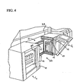
- FIG 2 shows that the pair of center panels 21,22 are doors which open inwardly into an open area or chamber 23 into which an operator can enter for working in close proximity with the conveyor path 25.
- each door has upper and lower hinges 40, each secured to an elongated key member 42 ( Figure 3 ) which -slides into an elongated horizontal keyway 41 which is part of the machine framework 46.
- each door can be completely removed from the machine by pulling the key 42 out of the keyway 41. With the doors removed the side opening 45 in the right hand cabinet C 1 and the side opening 47 in the left hand cabinet C 2 will be exposed thereby providing access from the side to the cabinets.
- a panel 50 ( Figure 2 ) covering the storage area beneath the conveyor path 25. This panel operates like the front left panel to provide access to the electronics stored behind this panel.
- the bottles pass through first, right hand, and second, left hand, inspection stations.
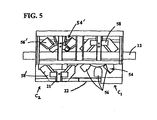
- the right hand station is defined by a right hand mirror assembly 54 which supports three mirrors 56 and is mounted in front of the conveyor path 25, a light source assembly 58 in the form of a large array of L.E.D.'s which is rigidly mounted behind the conveyor path on the machine frame 46, and a camera system (not shown) also mounted on the machine frame.
- the left hand station is defined by a mirror assembly 54' which supports three mirrors 56' and which is rigidly mounted behind the conveyor path 25 on the machine frame, a light source assembly 58' in the form of a large array of L.E.D.'s which is mounted in front of the conveyor path, and a camera system (not shown) also mounted on the machine frame.
- the right hand mirror assembly 54 is mounted on a horizontal arm 60 which is secured at its end proximate the conveyor path, to a vertical column 61 which is mounted on a pivot shaft 62 located at the right end of the machine.
- the right hand mirror assembly can therefore be pivotally displaced forwardly and rearwardly over the right hand cabinet containing the console 24, between a retracted service position shown in Figure 6 and the operating position shown in Figure 5 .
- the left end light source assembly 58' is mounted on a horizontal arm 70 which is secured at the interior end to a pivot shaft 72 located at the left end of the machine.
- the left hand light source assembly can therefore be pivotally displaced forwardly and rearwardly over the left hand cabinet having the front panel 20, between a retracted service position shown in Figure 6 and the operating position shown in Figure 5 where it (like the retracted right hand mirror assembly 54) will be clear of the open area or chamber 23, so that a serviceman can service the conveyor path and the equipment at the first and second inspection stations.
- an operator can step into the chamber 23 and conveniently address any issues involving bottles being conveyed along the conveyor, or service/clean all of the mirror and light source assemblies, camera lenses, etc.
Landscapes
- Engineering & Computer Science (AREA)
- Analytical Chemistry (AREA)
- General Health & Medical Sciences (AREA)
- Health & Medical Sciences (AREA)
- Life Sciences & Earth Sciences (AREA)
- Chemical & Material Sciences (AREA)
- Multimedia (AREA)
- Biochemistry (AREA)
- Physics & Mathematics (AREA)
- General Physics & Mathematics (AREA)
- Immunology (AREA)
- Pathology (AREA)
- Mechanical Engineering (AREA)
- Investigating Materials By The Use Of Optical Means Adapted For Particular Applications (AREA)
- Sorting Of Articles (AREA)
Claims (2)
- Maschine (10) zur Inspektion eines Behälters (14), der auf einem linearen Pfad durch die Maschine transportiert wird, mit:einem Fördermittel (12), das den linearen Pfad bereitstellt,ersten (C2) und zweiten (C1) Schrankmitteln vor dem Fördermittel an oder in gegenüberliegenden Richtungen des linearen Pfades,einem offenen Bereich (23) vor dem Fördermittel, der in Richtung des linearen Pfades zwischen benachbarten Seiten (47,45) der ersten und zweiten Schrankmittel definiert ist,ersten (21) und zweiten (22) Türen,ersten Scharniermitteln (40), die die erste Tür (21) an der Seite (47) des ersten Schrankmittels (C2) aufhängen, und zweiten Scharniermitteln (40), die die zweite Tür (22) an der Seite (45) des zweiten Schrankmittels (C1) aufhängt, um eine schwingende Bewegung der Türen zwischen einer geschlossen Position, in der sie kooperieren um die Frontseite zu verschließen und den Zugang in den offenen Bereich (23) zu versperren, und einer offenen Position auszuführen, um Zugang zu dem offenen Bereich zu ermöglichen,dadurch gekennzeichnet, dassdie benachbarten Seiten (47, 45) der ersten und zweiten Schrankmittel (C1, C2) offen sind,wobei die ersten und zweiten Scharniermittel (40) die ersten und zweiten Türen (21, 22) so aufhängen, dass sie von ihrer geschlossenen Position in eine offene Position gegen ihre zugehörigen offenen Seiten (47, 45) gedrückt werden können,wobei erste und zweite Befestigungsmittel (41, 42) vorgesehen sind, die an den entsprechenden ersten und zweiten Scharniermitteln gesichert und geeignet sind, die jeweiligen ersten und zweiten Türen (21, 22) entfernbar und austauschbar an ihren zugehörigen offenen Seiten (47, 45) zu befestigen, um den Türen zu gestatten, austauschbar von ihren Schrankmitteln entfernt zu werden, um den Zugang zu den offenen Seiten und dem Innenraum der ersten und zweiten Schrankmittel durch die offenen Seiten bereitzustellen.
- Maschine nach Anspruch 1, bei der jedes der Befestigungsmittel eine verlängerte horizontale Keilnut (41), die sich zur Frontseite der Maschine erstreckt und dem Maschinenrahmen (46) zugehörig ist, und ein verlängertes Keilelement (42) umfasst, das den zugehörigen Scharniermitteln (40) zugeordnet ist und verschiebbar in der Keilnut (41) befestigt ist.
Applications Claiming Priority (2)
| Application Number | Priority Date | Filing Date | Title |
|---|---|---|---|
| US10/610,060 US7073877B2 (en) | 2003-06-30 | 2003-06-30 | Container inspection machine |
| US610060 | 2006-12-13 |
Publications (2)
| Publication Number | Publication Date |
|---|---|
| EP1493501A1 EP1493501A1 (de) | 2005-01-05 |
| EP1493501B1 true EP1493501B1 (de) | 2009-08-05 |
Family
ID=33435381
Family Applications (1)
| Application Number | Title | Priority Date | Filing Date |
|---|---|---|---|
| EP04253475A Expired - Lifetime EP1493501B1 (de) | 2003-06-30 | 2004-06-10 | Maschine zur Kontrolle von Behältern mit einfachem Zugang zu ihren optischen und elektronischen Bauelementen für Wartungszwecke |
Country Status (4)
| Country | Link |
|---|---|
| US (1) | US7073877B2 (de) |
| EP (1) | EP1493501B1 (de) |
| JP (1) | JP2005024545A (de) |
| DE (1) | DE602004022360D1 (de) |
Families Citing this family (5)
| Publication number | Priority date | Publication date | Assignee | Title |
|---|---|---|---|---|
| JP4603937B2 (ja) * | 2005-06-06 | 2010-12-22 | 株式会社フジキカイ | 横型製袋充填機の供給コンベヤ |
| DE102010043635A1 (de) * | 2010-11-09 | 2012-05-10 | Krones Aktiengesellschaft | Vorrichtung zum Inspizieren von Behältern |
| DE102015106369B4 (de) * | 2015-04-24 | 2020-02-13 | Fette Engineering GmbH | Kapselfüllmaschine |
| CN105750220A (zh) * | 2016-04-27 | 2016-07-13 | 江苏楷益智能科技有限公司 | 一种瓶罐分拣装置 |
| CN115283294B (zh) * | 2022-08-19 | 2023-08-08 | 深圳市华卓实业有限公司 | 一种api检测的自动切割清洗设备及其加工工艺 |
Family Cites Families (18)
| Publication number | Priority date | Publication date | Assignee | Title |
|---|---|---|---|---|
| US2051946A (en) | 1934-06-11 | 1936-08-25 | George J Hewiett | Inspection device |
| US3434594A (en) | 1967-05-16 | 1969-03-25 | San Marino Electronic Corp | Empty bottle inspection machine |
| US3545134A (en) * | 1968-06-24 | 1970-12-08 | Amerock Corp | Cabinet frame and door for use with quickly attachable and detachable hinges |
| US3886356A (en) | 1973-09-10 | 1975-05-27 | Inex Inc | Optical inspection apparatus |
| US4417662A (en) * | 1981-05-04 | 1983-11-29 | Eli Lilly And Company | Vial inspection machine |
| US4655349A (en) * | 1984-12-27 | 1987-04-07 | Brockway, Inc. | System for automatically inspecting transparent containers for sidewall and dimensional defects |
| FR2642164B1 (fr) * | 1989-01-26 | 1991-04-12 | Saint Gobain Cinematique Contr | Controle d'objets a forte cadence |
| JPH0412696U (de) * | 1990-05-18 | 1992-01-31 | ||
| JPH04131485A (ja) * | 1990-09-21 | 1992-05-06 | Dantani Plywood Co Ltd | 扉装置 |
| EP0643295A3 (de) * | 1993-09-15 | 1995-05-03 | Emhart Glass Mach Invest | Gerät zur Behälterinspektion. |
| IT241558Y1 (it) * | 1996-05-30 | 2001-05-09 | Hager Lumetal | Armadio metallico per apparecchiature elettriche con montaggiomigliorato dei pannelli di chiusura frontali incernierati |
| NO316962B1 (no) * | 1996-07-12 | 2004-07-12 | Tomra Systems Asa | Anordning for handtering av beholdere |
| US5714998A (en) | 1997-01-13 | 1998-02-03 | Sony Corporation | Video inspection system for conveyors |
| US6226081B1 (en) | 1997-03-24 | 2001-05-01 | Optikos Corporation | Optical height of fill detection system and associated methods |
| GB2345940B (en) * | 1999-01-19 | 2002-08-14 | Vero Electronics Ltd | Hinge connection |
| JP2000320226A (ja) * | 1999-05-14 | 2000-11-21 | Atom Livin Tech Co Ltd | 両開き蝶番 |
| US6371580B1 (en) * | 2000-10-23 | 2002-04-16 | Emhart Glass S.A. | Console for glass forming machine |
| JP2002368444A (ja) * | 2001-06-11 | 2002-12-20 | Matsushita Electric Ind Co Ltd | 電子機器収容筐体の扉体蝶番装置 |
-
2003
- 2003-06-30 US US10/610,060 patent/US7073877B2/en not_active Expired - Fee Related
-
2004
- 2004-06-01 JP JP2004162735A patent/JP2005024545A/ja active Pending
- 2004-06-10 DE DE602004022360T patent/DE602004022360D1/de not_active Expired - Fee Related
- 2004-06-10 EP EP04253475A patent/EP1493501B1/de not_active Expired - Lifetime
Also Published As
| Publication number | Publication date |
|---|---|
| US7073877B2 (en) | 2006-07-11 |
| US20040262508A1 (en) | 2004-12-30 |
| EP1493501A1 (de) | 2005-01-05 |
| DE602004022360D1 (de) | 2009-09-17 |
| JP2005024545A (ja) | 2005-01-27 |
Similar Documents
| Publication | Publication Date | Title |
|---|---|---|
| US10451567B2 (en) | Radiographic product inspection system with reject bin | |
| EP1493502A1 (de) | Maschine zur Kontrolle von Behältern mit einfachem Zugang zu seinen optischen und elektronischen Bauelementen für Wartungszwecke | |
| KR20220092467A (ko) | 냉장고 | |
| US5740744A (en) | Through-wall type automatic customer service apparatus | |
| EP1432332A2 (de) | Oberkasten für einen spielautomaten mit einer tür | |
| CN101677696A (zh) | 用于展览物体的设备 | |
| EP1493501A1 (de) | Maschine zur Kontrolle von Behältern mit einfachem Zugang zu seinen optischen und elektronischen Bauelementen für Wartungszwecke | |
| US20120113248A1 (en) | Device for inspecting containers | |
| JP2011502791A (ja) | 品物を解体する装置と方法 | |
| EP0135338A2 (de) | Gleit- und Schwenkchassis-Anordnung für elektronische Ausrüstung | |
| US20040128915A1 (en) | Door for automated machine | |
| EP4146431B1 (de) | Laserbearbeitungskopf und laserbearbeitungssystem damit | |
| CN102261200B (zh) | 锁装置以及门窗 | |
| US3905444A (en) | Soundproofing enclosures | |
| JP2020102395A (ja) | 照明装置 | |
| CN1821650A (zh) | 用于一个工作设备的设备外壳 | |
| ATE247763T1 (de) | Betätigungsvorrichtung für tür- oder fensterkonstruktionen mit schwenkbaren flügelelementen | |
| CN217565335U (zh) | 一种图书存放箱及自助书柜 | |
| JP6831078B2 (ja) | 開閉装置およびその施工方法 | |
| CN217614805U (zh) | 一种用于mcb菌种分装的无菌隔离器 | |
| CN108513474A (zh) | 一种柜门平移旋转开启的控制柜 | |
| KR20060044589A (ko) | 양 여닫이식 롤링도어 | |
| GB2276651A (en) | Security screens | |
| KR102534342B1 (ko) | 교환이 용이한 광차단부재를 포함하는 광학검사장치 | |
| JP2017124677A (ja) | ホームドア装置 |
Legal Events
| Date | Code | Title | Description |
|---|---|---|---|
| PUAI | Public reference made under article 153(3) epc to a published international application that has entered the european phase |
Free format text: ORIGINAL CODE: 0009012 |
|
| AK | Designated contracting states |
Kind code of ref document: A1 Designated state(s): AT BE BG CH CY CZ DE DK EE ES FI FR GB GR HU IE IT LI LU MC NL PL PT RO SE SI SK TR |
|
| AX | Request for extension of the european patent |
Extension state: AL HR LT LV MK |
|
| 17P | Request for examination filed |
Effective date: 20050610 |
|
| AKX | Designation fees paid |
Designated state(s): DE FR GB IT |
|
| 17Q | First examination report despatched |
Effective date: 20060712 |
|
| GRAP | Despatch of communication of intention to grant a patent |
Free format text: ORIGINAL CODE: EPIDOSNIGR1 |
|
| RIC1 | Information provided on ipc code assigned before grant |
Ipc: G01N 21/90 20060101ALI20090122BHEP Ipc: E05D 7/12 20060101ALI20090122BHEP Ipc: B07C 5/342 20060101AFI20090122BHEP |
|
| GRAS | Grant fee paid |
Free format text: ORIGINAL CODE: EPIDOSNIGR3 |
|
| GRAA | (expected) grant |
Free format text: ORIGINAL CODE: 0009210 |
|
| AK | Designated contracting states |
Kind code of ref document: B1 Designated state(s): DE FR GB IT |
|
| REG | Reference to a national code |
Ref country code: GB Ref legal event code: FG4D |
|
| REF | Corresponds to: |
Ref document number: 602004022360 Country of ref document: DE Date of ref document: 20090917 Kind code of ref document: P |
|
| PLBE | No opposition filed within time limit |
Free format text: ORIGINAL CODE: 0009261 |
|
| STAA | Information on the status of an ep patent application or granted ep patent |
Free format text: STATUS: NO OPPOSITION FILED WITHIN TIME LIMIT |
|
| 26N | No opposition filed |
Effective date: 20100507 |
|
| GBPC | Gb: european patent ceased through non-payment of renewal fee |
Effective date: 20100610 |
|
| REG | Reference to a national code |
Ref country code: FR Ref legal event code: ST Effective date: 20110228 |
|
| PG25 | Lapsed in a contracting state [announced via postgrant information from national office to epo] |
Ref country code: IT Free format text: LAPSE BECAUSE OF NON-PAYMENT OF DUE FEES Effective date: 20100610 |
|
| PG25 | Lapsed in a contracting state [announced via postgrant information from national office to epo] |
Ref country code: DE Free format text: LAPSE BECAUSE OF NON-PAYMENT OF DUE FEES Effective date: 20110101 |
|
| PG25 | Lapsed in a contracting state [announced via postgrant information from national office to epo] |
Ref country code: FR Free format text: LAPSE BECAUSE OF NON-PAYMENT OF DUE FEES Effective date: 20100630 |
|
| PG25 | Lapsed in a contracting state [announced via postgrant information from national office to epo] |
Ref country code: GB Free format text: LAPSE BECAUSE OF NON-PAYMENT OF DUE FEES Effective date: 20100610 |