EP1492115B1 - Data recording device and method, data reproduction device and method, information recording medium, program-containing medium, and program - Google Patents
Data recording device and method, data reproduction device and method, information recording medium, program-containing medium, and program Download PDFInfo
- Publication number
- EP1492115B1 EP1492115B1 EP03715478A EP03715478A EP1492115B1 EP 1492115 B1 EP1492115 B1 EP 1492115B1 EP 03715478 A EP03715478 A EP 03715478A EP 03715478 A EP03715478 A EP 03715478A EP 1492115 B1 EP1492115 B1 EP 1492115B1
- Authority
- EP
- European Patent Office
- Prior art keywords
- information
- frame
- data
- frame array
- array
- Prior art date
- Legal status (The legal status is an assumption and is not a legal conclusion. Google has not performed a legal analysis and makes no representation as to the accuracy of the status listed.)
- Expired - Lifetime
Links
Images


Classifications
-
- H—ELECTRICITY
- H04—ELECTRIC COMMUNICATION TECHNIQUE
- H04N—PICTORIAL COMMUNICATION, e.g. TELEVISION
- H04N9/00—Details of colour television systems
- H04N9/79—Processing of colour television signals in connection with recording
- H04N9/80—Transformation of the television signal for recording, e.g. modulation, frequency changing; Inverse transformation for playback
- H04N9/804—Transformation of the television signal for recording, e.g. modulation, frequency changing; Inverse transformation for playback involving pulse code modulation of the colour picture signal components
- H04N9/8042—Transformation of the television signal for recording, e.g. modulation, frequency changing; Inverse transformation for playback involving pulse code modulation of the colour picture signal components involving data reduction
-
- G—PHYSICS
- G11—INFORMATION STORAGE
- G11B—INFORMATION STORAGE BASED ON RELATIVE MOVEMENT BETWEEN RECORD CARRIER AND TRANSDUCER
- G11B20/00—Signal processing not specific to the method of recording or reproducing; Circuits therefor
- G11B20/10—Digital recording or reproducing
-
- G—PHYSICS
- G11—INFORMATION STORAGE
- G11B—INFORMATION STORAGE BASED ON RELATIVE MOVEMENT BETWEEN RECORD CARRIER AND TRANSDUCER
- G11B20/00—Signal processing not specific to the method of recording or reproducing; Circuits therefor
- G11B20/10—Digital recording or reproducing
- G11B20/12—Formatting, e.g. arrangement of data block or words on the record carriers
- G11B20/1217—Formatting, e.g. arrangement of data block or words on the record carriers on discs
-
- G—PHYSICS
- G11—INFORMATION STORAGE
- G11B—INFORMATION STORAGE BASED ON RELATIVE MOVEMENT BETWEEN RECORD CARRIER AND TRANSDUCER
- G11B27/00—Editing; Indexing; Addressing; Timing or synchronising; Monitoring; Measuring tape travel
-
- G—PHYSICS
- G11—INFORMATION STORAGE
- G11B—INFORMATION STORAGE BASED ON RELATIVE MOVEMENT BETWEEN RECORD CARRIER AND TRANSDUCER
- G11B27/00—Editing; Indexing; Addressing; Timing or synchronising; Monitoring; Measuring tape travel
- G11B27/02—Editing, e.g. varying the order of information signals recorded on, or reproduced from, record carriers
- G11B27/031—Electronic editing of digitised analogue information signals, e.g. audio or video signals
- G11B27/034—Electronic editing of digitised analogue information signals, e.g. audio or video signals on discs
-
- G—PHYSICS
- G11—INFORMATION STORAGE
- G11B—INFORMATION STORAGE BASED ON RELATIVE MOVEMENT BETWEEN RECORD CARRIER AND TRANSDUCER
- G11B27/00—Editing; Indexing; Addressing; Timing or synchronising; Monitoring; Measuring tape travel
- G11B27/10—Indexing; Addressing; Timing or synchronising; Measuring tape travel
- G11B27/102—Programmed access in sequence to addressed parts of tracks of operating record carriers
- G11B27/105—Programmed access in sequence to addressed parts of tracks of operating record carriers of operating discs
-
- G—PHYSICS
- G11—INFORMATION STORAGE
- G11B—INFORMATION STORAGE BASED ON RELATIVE MOVEMENT BETWEEN RECORD CARRIER AND TRANSDUCER
- G11B27/00—Editing; Indexing; Addressing; Timing or synchronising; Monitoring; Measuring tape travel
- G11B27/10—Indexing; Addressing; Timing or synchronising; Measuring tape travel
- G11B27/19—Indexing; Addressing; Timing or synchronising; Measuring tape travel by using information detectable on the record carrier
- G11B27/28—Indexing; Addressing; Timing or synchronising; Measuring tape travel by using information detectable on the record carrier by using information signals recorded by the same method as the main recording
- G11B27/32—Indexing; Addressing; Timing or synchronising; Measuring tape travel by using information detectable on the record carrier by using information signals recorded by the same method as the main recording on separate auxiliary tracks of the same or an auxiliary record carrier
- G11B27/327—Table of contents
- G11B27/329—Table of contents on a disc [VTOC]
-
- H—ELECTRICITY
- H04—ELECTRIC COMMUNICATION TECHNIQUE
- H04N—PICTORIAL COMMUNICATION, e.g. TELEVISION
- H04N5/00—Details of television systems
- H04N5/76—Television signal recording
- H04N5/91—Television signal processing therefor
- H04N5/92—Transformation of the television signal for recording, e.g. modulation, frequency changing; Inverse transformation for playback
-
- G—PHYSICS
- G11—INFORMATION STORAGE
- G11B—INFORMATION STORAGE BASED ON RELATIVE MOVEMENT BETWEEN RECORD CARRIER AND TRANSDUCER
- G11B2220/00—Record carriers by type
- G11B2220/20—Disc-shaped record carriers
- G11B2220/25—Disc-shaped record carriers characterised in that the disc is based on a specific recording technology
- G11B2220/2537—Optical discs
- G11B2220/2562—DVDs [digital versatile discs]; Digital video discs; MMCDs; HDCDs
-
- H—ELECTRICITY
- H04—ELECTRIC COMMUNICATION TECHNIQUE
- H04N—PICTORIAL COMMUNICATION, e.g. TELEVISION
- H04N5/00—Details of television systems
- H04N5/76—Television signal recording
- H04N5/84—Television signal recording using optical recording
- H04N5/85—Television signal recording using optical recording on discs or drums
-
- H—ELECTRICITY
- H04—ELECTRIC COMMUNICATION TECHNIQUE
- H04N—PICTORIAL COMMUNICATION, e.g. TELEVISION
- H04N9/00—Details of colour television systems
- H04N9/79—Processing of colour television signals in connection with recording
- H04N9/7921—Processing of colour television signals in connection with recording for more than one processing mode
-
- H—ELECTRICITY
- H04—ELECTRIC COMMUNICATION TECHNIQUE
- H04N—PICTORIAL COMMUNICATION, e.g. TELEVISION
- H04N9/00—Details of colour television systems
- H04N9/79—Processing of colour television signals in connection with recording
- H04N9/80—Transformation of the television signal for recording, e.g. modulation, frequency changing; Inverse transformation for playback
- H04N9/82—Transformation of the television signal for recording, e.g. modulation, frequency changing; Inverse transformation for playback the individual colour picture signal components being recorded simultaneously only
- H04N9/8205—Transformation of the television signal for recording, e.g. modulation, frequency changing; Inverse transformation for playback the individual colour picture signal components being recorded simultaneously only involving the multiplexing of an additional signal and the colour video signal
Definitions
- the present invention relates to a data-recording apparatus, a data-recording method, a data reproducing apparatus, a data reproducing method, an information-recording medium, a program storage medium and a program. More particularly, the present invention relates to a data-recording apparatus, a data-recording method, a data reproducing apparatus, a data reproducing method, an information-recording medium, a program storage medium and a program that are each usable as means for determining a reproduction position with a high degree of reliability for data recorded on the information-recording medium even after the data is edited.
- a DV (Digital Video) method is one of high-performance encoding methods for compressing the amount of information conveyed by an AV (Audio Visual) signal.
- the DV encoding method is disclosed in a document with a title of 'Specification of Consumer-Use Digital VCRs using 6.3mm magnetic tape' disclosed in an HD DIGITAL VCR CONFERENCE.
- the DV method is adopted in applications such as a camcoder using a video cassette tape.
- a camcoder is a video tape recorder integrated with a camera to form a single apparatus.
- a DV signal can be input and output by way of an IEEE (Institute of Electrical and Electronic Engineers) 1394 digital interface, which is referred to hereafter simply as an IEEE 1394 I/F.
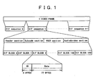
- IEEE 1394 I/F The format of a signal flowing through the IEEE 1394 I/F is shown in Fig. 1 .
- the IEEE 1394 I/F handles a DV signal in 80-byte block units each known as a DIF (Directory Interchange Format) block.
- DIF blocks form 1 DIF sequence.
- a DIF sequence comprises a header section, a subcode section, a VAUX section and an audio & video section.
- SD-DVCR which is a standard compression mode of a standard TV (television) signal
- one video frame comprises 10 DIF sequences in a 525-60 system such as the NTSC (National Television System Committee) or 12 DIF sequences in a 625-60 system such as the PAL (Phase Alternating Line).
- one video frame comprises 5 DIF sequences in a 525-60 system or 6 DIF sequences in a 625-50 system.
- a DIF block comprises a 3-byte ID (Identifier) located at the beginning of the block and 77-byte data following the ID.
- the ID includes a DIF block type, a sequence number representing a color sequence, a DIF sequence number and a DIF block number.
- the DIF block type indicates the type of a section including the block. If a DIF block type indicates a header section, the DIF block with an ID including the DIF block is located at the beginning of a DIF sequence.
- a DIF block included in a header section has 3 most significant bits of 000 in the first byte thereof.
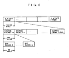
- a DV signal having such a format flows through an IEEE 1394 I/F as isochronous packets.
- the payload of an isochronous packet conveying a DV signal is referred to as a source packet.
- a source packet has a fixed length of 6 DIF blocks or 480 bytes.
- FIG. 2 A relation between a source packet and DIF blocks in the 525-60 system is shown in Fig. 2 .
- All frames of a DV stream are subjected to an intra-frame encoding process to generate frames each having a fixed bit rate (length) of 120,000 bytes.
- the number of source packets per video frame is also fixed. That is to say, the number of source packets per video frame in the SD-DVCR mode is 250 for the 525-60 system or 300 for the 625-50 system.
- optical discs as an information-recording medium implemented in the form of a disc that can be dismounted from a recording/reproducing apparatus.
- Such an optical disc usable for recording data is characterized in that the disc can be used as recording media having a large storage capacity of several gigabytes and allowing a high transfer bit rate of several tens of Mbps.
- the optical disc is very much expected to serve as storage media for recording an AV (Audio Visual) such as a video signal.
- the recording medium can be used for storing a large amount of data such as image and sound data of video materials. That is to say, the recording medium can be used for storing a large number of DV video materials. In consequence, there will be required an operation such as an editing work for producing a result, which allows the user to watch desired images selected from those numerous DV video materials recorded on the disc.
- a data-recording apparatus including: a control unit for assigning frame array identification information to each of frame arrays each comprising successive frames; and acquiring leading-data information for each of the frame arrays as information representing the length of data located at the beginning of the frame array as a part not belonging to the frame array, wherein the beginning of said leading-data information coincides with a sector boundary ; acquiring trailing-data information for each of the frame arrays as information representing the length of data located at the end of the frame array as a part not belonging to the frame array, wherein the end of said trailing-data information coincides with a sector boundary, acquiring first information for each of the frame arrays as information for identifying a frame located at the beginning of the frame array; and acquiring second information for each of the frame arrays as information representing the number of frames included in the frame array; and a recording unit for recording the leading-data information, the trailing-data information, the first information and the second information along with the frame array identification information into an information-recording medium by associating
- the data-recording apparatus is possible to implement as a special-purpose apparatus for carrying out recording operations only or as a block for performing a recording process of an apparatus for carrying out both recording and reproducing operations.
- the video data is video data with all the frames thereof having a uniform amount of data.
- the first information is an offset number representing a frame number assigned to a frame located at the beginning of the frame array and the second information is the number of frames included in the frame array.
- the first information is a reproduction start frame number representing a frame number assigned to a frame located at the beginning of the frame array and the second information is a reproduction end frame number representing a frame number assigned to a frame located at the end of the frame array.
- the first information is an offset reproduction start time representing a frame located at the beginning of the frame array and the second information is an offset reproduction end time representing a frame located at the end of the frame array.
- a data-recording method including the steps of: assigning frame array identification information to each of frame arrays each comprising successive frames; generating leading-data information for each of the frame arrays as information representing the length of data located at the beginning of the frame array as a part not belonging to the frame array, wherein the beginning of said leading-data information coincides with a sector boundary; generating trailing-data information for each of the frame arrays as information representing the length of data located at the end of the frame array as a part not belonging to the frame, array, wherein the end of said trailing-data information coincides with a sector boundary; detecting first information for each of the frame arrays as information for identifying a frame located at the beginning of the frame array; and computing second information for each of the frame arrays as information representing the number of frames included in the frame array; and recording the leading-data information, the trailing-data information, the first information and the second information along with the frame array identification information into an information-recording medium by associating the leading-data information, the trail
- a first program storage medium provided by the present invention as a program storage medium for storing a program, including the steps of: assigning frame array identification information to each of frame arrays each comprising successive frames; generating leading-data information for each of the frame arrays as information representing the length of data located at the beginning of the frame array as a part not belonging to the frame array, wherein the beginning of said leading-data information coincides with a sector boundary; generating trailing-data information for each of the frame arrays as information representing the length of data located at the end of the frame array as a part not belonging to the frame array, wherein the end of said trailing-data information coincides with a sector boundary; detecting first information for each of the frame arrays as information for identifying a frame located at the beginning of the frame array; and computing second information for each of the frame arrays as information representing the number of frames included in the frame array; and recording the leading-data information, the trailing-data information, the first information and the second information along with the frame array identification information into an information-recording medium by associ
- a first program is executed by a computer to carry out processing, including the steps of: assigning frame array identification information to each of frame arrays each comprising successive frames; generating leading-data information for each of the frame arrays as information representing the length of data located at the beginning of the frame array as a part not belonging to the frame array, wherein the beginning of said leading-data information coincides with a sector boundary; generating trailing-data information for each of the frame arrays as information representing the length of data located at the end of the frame array as a part not belonging to the frame array, wherein the end of said trailing-data information coincides with a sector boundary; detecting first information for each of the frame arrays as information for identifying a frame located at the beginning of the frame array; and computing second information for each of the frame arrays as information representing the number of frames included in the frame array; and recording the leading-data information, the trailing-data information, the first information and the second information along with the frame array identification information into an information-recording medium by associating the leading-data information, the
- a data reproducing apparatus including: a reproduction unit for reproducing the following pieces of information from an information-recording medium: frame array identification information for identifying each frame array comprising successive frames; leading-data information representing the length of data located at the beginning of the frame array as a part not belonging to the frame array, wherein the beginning of said leading-data information coincides with a sector boundary; trailing-data information representing the length of data located at the end of the frame array as a part not belonging to the frame array, wherein the end of said trailing-data information coincides with a sector boundary; first information for identifying a frame located at the beginning of the frame array; and second information representing the number of frames included in the frame array; and a control unit for controlling a reproduction position of a specified frame on the basis of the frame array identification information, the leading-data information, the trailing-data information, the first information and the second information.
- the data reproducing apparatus is possible to implement as a special-purpose apparatus for carrying out reproducing operations only or as a block for performing a reproduction process of an apparatus for carrying out both recording and reproducing operations.
- the first information is an offset number representing a frame number assigned to a frame located at the beginning of the frame array and the second information is the number of frames included in the frame array.
- the control unit computes the reproduction position of the specified frame by executing the steps of: computing a difference between a specified-frame identification number used for specifying the specified frame and the offset number of a specific frame array including the specified frame; multiplying the difference by the uniform amount of data in order to result in a product; and adding the product to a sum of the leading-data information for the specific frame array and the amount of data included in a previous frame array immediately preceding the specific frame array on a time base in order to result in the reproduction position.
- control unit computes the amount of data included in the previous frame array immediately preceding the specific frame array on a time base by executing the steps of: multiplying the uniform amount of data by the number of frames included in the previous frame array in order to result in a product; and adding the product to a sum of the leading-data information of the previous frame array and the trailing-data information of the previous frame array in order to result in the amount of data included in the previous frame array.
- the first information is a reproduction start frame number representing a frame number assigned to a frame located at the beginning of the frame array and the second information is a reproduction end frame number representing a frame number assigned to a frame located at the end of the frame array.
- the control unit computes the reproduction position of the specified frame by executing the steps of: computing a difference between a specified-frame identification number used for specifying the specified frame and the first information representing the reproduction start frame number of a specific frame array including the specified frame; multiplying the difference by the uniform amount of data in order to result in a product; and adding the product to a sum of the leading-data information for the specific frame array and the amount of data included in a previous frame array immediately preceding the specific frame array on a time base in order to result in the reproduction position.
- control unit computes the amount of data included in the previous frame array immediately preceding the specific frame array on a time base by executing the steps of: computing a difference between the reproduction end frame number of the previous frame array and the reproduction start frame number of the previous frame array in order to result in the number of frames included in the previous frame array; multiplying the uniform amount of data by the difference in order to result in a product; and adding the product to a sum of the leading-data information of the previous frame array and the trailing-data information of the previous frame array in order to result in the amount of data included in the previous frame array.
- the first information is an offset reproduction start time representing a frame located at the beginning of the frame array and the second information is an offset reproduction end time representing a frame located at the end of the frame array.
- the control unit computes the reproduction position of the specified frame by executing the steps of: computing a difference between a specified-frame identification number used for specifying the specified frame and the first information representing the offset reproduction start time of a specific frame array including the specified frame; multiplying the difference by the uniform amount of data in order to result in a product; and adding the product to a sum of the leading-data information for the specific frame array and the amount of data included in a previous frame array immediately preceding the specific frame array on a time base in order to result in the reproduction position.
- control unit computes the amount of data included in the previous frame array by executing the steps of:
- a data reproducing method including the steps of: reproducing frame array identification information for identifying each frame array comprising successive frames from an information-recording medium; reproducing leading-data information representing the length of data located at the beginning of the frame array as a part not belonging to the frame array from the information-recording medium, wherein the beginning of said leading-data information coincides with a sector boundary; reproducing trailing-data information representing the length of data located at the end of the frame array as a part not belonging to the frame array from the information-recording medium, wherein the end of said trailing-data information coincides with a sector boundary; reproducing first information for identifying a frame located at the beginning of the frame array from the information-recording medium; reproducing second information representing the number of frames included in the frame array from the information-recording medium; and controlling a reproduction position of a specified frame on the basis of the frame array identification information, the leading-data information, the trailing-data information, the first information and the second information.
- a second program storage medium provided by the present invention as a program storage medium for storing a program, including the steps of: reproducing frame array identification information for identifying each frame array comprising successive frames from an information-recording medium; reproducing leading-data information representing the length of data located at the beginning of the frame array as a part not belonging to the frame array from the information-recording medium, wherein the beginning of said leading-data information coincides with a sector boundary; reproducing trailing-data information representing the length of data located at the end of the frame array as a part not belonging to the frame array from the information-recording medium, wherein the end of said trailing-data information coincides with a sector boundary; reproducing first information for identifying a frame located at the beginning of the frame array from the information-recording medium; reproducing second information representing the number of frames included in the frame array from the information-recording medium; and controlling a reproduction position of a specified frame on the basis of the frame array identification information, the leading-data information, the trailing-data information, the first information
- a second program which is executed by a computer to carry out processing including the steps of: reproducing frame array identification information for identifying each frame array comprising successive frames from an information-recording medium; reproducing leading-data information representing the length of data located at the beginning of the frame array as a part not belonging to the frame array from the information-recording medium, wherein the beginning of said leading-data information coincides with a sector boundary; reproducing trailing-data information representing the length of data located at the end of the frame array as a part not belonging to the frame array from the information-recording medium, wherein the end of said trailing-data information coincides with a sector boundary; reproducing first information for identifying a frame located at the beginning of the frame array from the information-recording medium; reproducing second information representing the number of frames included in the frame array from the information-recording medium; and controlling a reproduction position of a specified frame on the basis of the frame array identification information, the leading-data information, the trailing-data information, the first information and the second
- An information-recording medium provided by the present invention that is used for storing: frame array identification information for identifying each frame array comprising successive frames; leading-data information representing the length of data located at the beginning of the frame array as a part not belonging to the frame array, wherein the beginning of said leading-data information coincides with a sector boundary; trailing-data information representing the length of data located at the end of the frame array as a part not belonging to the frame array, wherein the end of said trailing-dara information coincides with a sector boundary; first information for identifying a frame located at the beginning of the frame array; and second information representing the number of frames included in the frame array.
- processing is carried out to execute the steps of: assigning frame array identification information to each of frame arrays each comprising successive frames; generating leading-data information for each of the frame arrays as information representing the length of data located at the beginning of the frame array as a part not belonging to the frame array, wherein the beginning of said leading-data information coincides with a sector boundary; generating trailing-data information for each of the frame arrays as information representing the length of data located at the end of the frame array as a part not belonging to the frame array, wherein the end of said trailing-data information coincides with a sector boundary; detecting first information for each of the frame arrays as information for identifying a frame located at the beginning of the frame array; and computing second information for each of the frame arrays as information representing the number of frames included in the frame array; and recording the leading-data information, the trailing-data information, the first information and the second information along with
- the data reproducing apparatus the data reproducing method, the second program storage medium and the second program, which are provided by the present invention, processing is carried out to execute the steps of: reproducing frame array identification information for identifying each frame array comprising successive frames from an information-recording medium; reproducing leading-data information representing the length of data located at the beginning of the frame array as a part not belonging to the frame array from the information-recording medium, wherein the beginning of said leading-data information coincides with a sector boundary; reproducing trailing-data information representing the length of data located at the end of the frame array as a part not belonging to the frame array from the information-recording medium wherein the end of said trailing-data information coincides with a sector boundary; reproducing first information for identifying a frame located at the beginning of the frame array from the information-recording medium; reproducing second information representing the number of frames included in the frame array from the information-recording medium; and controlling a reproduction position of a specified frame on the basis of the frame array identification information, the leading-data information
- the information-recording medium provided by the present invention is used for storing: frame array identification information for identifying each frame array comprising successive frames; leading-data information representing the length of data located at the beginning of the frame array as a part not belonging to the frame array, wherein the beginning of said leading-data information coincides with a sector boundary; trailing-data information representing the length of data located at the end of the frame array as a part not belonging to the frame array, wherein the end of said trailing-data information coincides with a sector boundary; first information for identifying a frame located at the beginning of the frame array; and second information representing the number of frames included in the frame array.
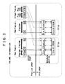
- Fig. 3 is a diagram showing a simplified structure of an application format on a recording medium (or a recording medium 10 shown in Fig. 27 to be described later).
- the format has two layers, namely, Clip and Playlist layers for managing an AV stream. Volume information is used for managing all Clip and Playlist objects on a disc.
- a pair of an AV stream file and affiliated information thereof is handled as a Clip object.
- a Clip AV stream file is the AV stream file and a Clip information file is a file containing the affiliated information of the AV stream file.
- a Clip AV stream file is used for storing data obtained as a result of laying out a DV stream in a structure prescribed in accordance with a DVR (Digital Video Recording) application format.
- DVR Digital Video Recording
- a data file used in a computer or the like is handled as an array of bytes.
- a content of a Clip AV stream is spread along the time base and Playlist specifies an access point in Clip mainly as a timestamp. If PlayList gives a timestamp of an access point in Clip, the Clip information file is useful for finding an address in a CLIP AV stream file as an address at which a decoding process is to be started.
- PlayList can be used to select reproduction sections, which the user wants to watch, from those included in Clip and allow the selected reproduction sections to be edited with ease.
- a PlayList object is a collection of reproduction sections selected from Clip.
- a reproduction section included in a certain Clip object is referred to as PlayItem.
- PlayItem is represented by a pair of an IN point and an OUT point, which exist on the time base.
- PlayList is a collection of PlayItem objects.
- PlayList types There are two PlayList types, namely, Real PlayList and Virtual PlayList.
- Real PlayList is PlayList including PlayItem objects sharing a Clip object referenced by PlayList. That is to say, Real PlayList occupies a disc area with a data storage capacity corresponding to the stream portions of Clip referenced by PlayList.
- Real PlayList referencing the entire reproducible range of the new Clip object is automatically generated. If a portion of the reproducible range of Real PlayList is erased, data of a Clip stream portion referenced by the erased portion of the reproducible range of Real PlayList is also deleted.
- Virtual PlayList is PlayList including PlayItem objects sharing no Clip object. Even if Virtual PlayList is modified or deleted, no changes are made to Clip objects referenced by Virtual PlayList.
- Real PlayList and Virtual PlayList are referred to simply as PlayList, a generic name given to both.
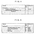
- Fig. 4 is a diagram showing the syntax of PlayList ( ) stored in a PlayList file.
- number_of_PlayItems is the number of PlayItem objects included in PlayList.
- Fig. 5 is a diagram showing the syntax of PlayItem ( ).
- Clip_Information_file_name is the name of a File Information file referenced by PlayItem.
- connection_condition is information indicating whether or not current PlayItem is connected seamlessly to preceding PlayItem.
- IN_time is the number of a frame read out at the start time of an operation to reproduce PlayItem.
- OUT_time is the number of a frame read out at the end time of an operation to reproduce PlayItem.
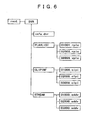
- the top directory is a root directory including a DVR directory.
- the DVR directory further includes PLAYLIST, CLIPINF and STREAM directories.
- Fig. 6 is a diagram showing a typical structure of directories on a DVR disc.
- the root directory includes only one directory, namely, the DVR directory.
- the DVR directory accommodates all files prescribed in the DVR application format and other directories.
- the other directories included in the DVR directory are described as follows:
- a file named xxxxx.rpls is used for storing information related to a Real PlayList object. That is to say, a file named xxxxx.rpls is provided for each Real PlayList. 'xxxxx' of the file name is 5 numerical digits each having a value in the range 0 to 9. 'rpls' is the extension of the file name.
- a file named yyyyy.vpls is used for storing information related to a Virtual PlayList object. That is to say, a file named yyyyy.vpls is provided for each Virtual PlayList.
- 'yyyyyy' of the file name is 5 numerical digits each having a value in the range 0 to 9.
- 'vpls' is the extension of the file name.
- the CLIPINF directory accommodates Clip information files each associated with an AV stream file accommodated in the STREAM directory.
- An AV stream file associated with a Clip information file named zzzzz.clpi is a CLIP AV stream file or a Bridge-Clip AV stream file.
- 'zzzzz' of the file name is 5 numerical digits each having a value in the range 0 to 9.
- 'clpi' is the extension of the file name.
- the STREAM directory accommodates AV stream files each named zzzzz.sddv.
- An AV stream file is a file handled by a DVR system. As described above, an AV stream file is a CLIP AV stream file or a Bridge-Clip AV stream file.
- 'zzzzz' of the file name is 5 numerical digits each having a value in the range 0 to 9.
- 'sddv' is the extension of the file name.
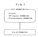
- Fig. 7 is a diagram showing a relation between a Clip information file and a Clip AV stream file.
- a Clip information file is a database file for managing data contained in a Clip AV stream file associated with the Clip information file and time base information on the AV stream stored in the Clip AV stream file.
- the Clip information file contains ClipInfo for managing the data contained in the Clip AV stream file, Program-sequence information and DVF-sequence information for managing the time base information on the AV stream.
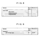
- Fig. 8 is a diagram showing the syntax of the Clip information file. As shown in the figure, this Clip information file contains ClipInfo ( ), SequenceInfo ( ) and ProgramInfo ( ).
- Fig. 9 is a diagram showing the syntax of ClipInfo ( ).
- DV_format_type is the type of DV_format of an AV stream file associated with this Clip. From DV_format_type, it is possible to know the number of data bytes included in 1 DV stream.
- DV_format_type may indicate an SD-DVCR 525-60 system with a byte count of 120,000 bytes, an SD-DVCR 625-50 system with a byte count of 144,000 bytes, an SDL-DVCR 525-60 system with a byte count of 60,000 bytes or an SDL-DVCR 625-50 system with a byte count of 72,000 bytes.
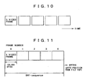
- An AV stream file is recorded with 1 video frame of a DV signal format taken as a unit as shown in Fig. 2 .
- the DV signal format is the format of a DV signal flowing through an IEEE 1394 I/F
- a DV stream is input in frame units. If the DV stream is to be newly recorded onto a recording medium, as shown in Fig. 11 , pieces of data of the input DV frames are squeezed sequentially in an AV stream file. Logically, the DV stream is recorded in the AV stream file as a continuous array of bytes. In the example shown in the figure, the DV stream is recorded in the AV stream file as an array of bytes composing frames with frame numbers 0, 1, 2, 3 and 4.
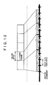
- Fig. 12 is an explanatory diagram referred to in describing the DVF sequence shown in Fig. 11 .
- the horizontal axis represents byte positions starting with the byte position at the beginning of the file.
- the vertical axis represents frame numbers.
- frame numbers are assigned to frames of the DV stream sequentially in the order the frames are recorded into the AV stream file as shown in Fig. 12 .
- An array of bytes composing DV frames with regularly increasing frame numbers assigned thereto in an AV stream file is referred to as a DVF-sequence.
- a DVF-sequence In the case of the example shown in Fig.
- the array of bytes composing 5 frames with regularly increasing frame numbers of 0 to 4 assigned thereto forms one DVF-sequence. That is to say, in the period T of one DVF-sequence, the frame numbers assigned to the frames composing the DVF-sequence are regularly increasing numbers. If the DV stream is newly recorded on a recording medium, Clip for the stream has only one DVF-sequence, including no point of discontinuity in the series of regularly increasing DV frame numbers.
- Fig. 13 shows the top of the DVF-sequence for the newly recorded AV stream file and the lower portion of Fig. 13 shows a typical layout of data recorded on the recording medium in the recording operation.
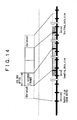
- Fig. 14 is a diagram showing a layout of data recorded on the disc after an operation to partially delete frames of the data from the beginning and the end of the DVF-sequence shown in Fig. 13 .
- the data-deleting operation the data is deleted from the beginning of the DVF-sequence in such a way that the top of the resulting DVF-sequence is aligned to a sector boundary. (It is to be noted that data is deleted in sector units.) Since the top of the resulting DVF-sequence is aligned to a sector boundary, data of an incomplete frame data referred to as Leading_data_size precedes the first complete DV frame.
- the data of the rear frame is deleted from the end of the DVF-sequence in such a way that the end of the resulting DVF-sequence is aligned to a sector boundary. Since the end of the resulting DVF-sequence is aligned to a sector boundary, data of an incomplete frame data referred to as Trailing_data_size succeeds the last complete DV frame.
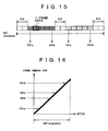
- Fig. 15 is a diagram showing a DVF-sequence obtained as a result of an operation to newly record a DV stream onto a recording medium.
- Fig. 16 is a diagram showing a pre-deletion (pre-editing) relation between the positions of bytes in the DVF-sequence shown in Fig.
- Fig. 16 is similar to Fig. 12 .
- the frame number (FN) of the DVF-sequence is proportional to the byte count.
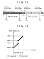
- 2 DVF-sequences are generated in Clip shown in Fig. 17 .
- DVF-sequence#0 is the first DVF-sequence
- DVF-sequence#1 is the second DVF-sequence.
- Fig. 18 is a diagram showing the DVF-sequences shown in Fig. 17 and the frame numbers. In this case, the boundary between the 2 DVF-sequences is a point of discontinuity in the series of regularly increasing DV frame numbers. As shown in Fig.
- DVF-sequence#0 includes pieces of data referred to as Leading_data_size#0 and Trailing_data_size#0
- DVF-sequence#1 includes pieces of data referred to as Leading_data_size#1 and Trailing_data_size#1.
- the following description explains a method of making a random access to an arbitrary frame in the AV stream file by using information on the DVF-sequence for the file.
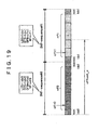
- Fig. 19 is a diagram showing an AV stream file having 2 DVF-sequences.
- the following description explains a method of making a random access to an xth frame in the second DVF-sequence, that is, DVF-sequence#1 shown in the figure.
- the number of bytes in an offset between the top of the file and the top of the xth frame is computed by using Eqs. 1 and 2 shown below.
- the offset is denoted by notation offset_x.
- DVF_sequence_size [0] denotes the number of bytes in the first DVF-sequence, that is, DVF-sequence#0, notation lds0 denotes Leading_data_size of DVF-sequence#0, notation tds0 denotes Trailing_data_size of DVF-sequence#0, notation nf0 denotes the number of DV frames in DVF-sequence#0, notation FS denotes the number of bytes in 1 DV frame, notation lds1 denotes Leading_data_size of DVF-sequence#1 and notation ofn1 is the
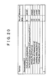
- Fig. 20 is a diagram showing the syntax of SequenceInfo ( ). Num_of_DVF_sequences is the number of DFV-sequences included in the AV stream file.
- Offset_FN_DVF [dvf_id] is the offset frame number assigned to the first DV frame in a DVF-sequence referenced by a DVF-sequence ID denoted by notation dvf_id as one of DVF-sequences included in the AV stream file.
- Leading_data_size [dvf_id] is the number of bytes in data preceding the first DV frame in a DVF-sequence referenced by dvf_id.
- Trailing_data_size [dvf_id] is the number of bytes in data succeeding the last DV frame in a DVF-sequence referenced by dvf_id.
- Number_of_frames [dvf_id] is the number of frames referenced in a DVF-sequence indicated by dvf_id.
- the frames included in a DVF-sequence is frames included in a reproduction section, which begins with the first DV frame and ends with the last DV frame.
- Offset_FN_DVF [dvf_id] in SequenceInfo ( ) are regularly increasing numbers satisfying conditions expressed by Eqs. (3) and (4) as follows: Offset_FN_DVF dvf_id ⁇ 0 For dvf_id satisfying 0 ⁇ dvf_id ⁇ num_of_DVF_sequences, Offset_FN_DVF dvf_id > Offset_FN_DVF dvf_id - 1 + Number_of_frames dvf_id - 1
- the explained relation between the DVF-sequence and PlayList is a relation obtained as a result of an operation to partially delete data of a Clip AV stream in typically an editing process as described above.
- Offset_FN_DVF [0] of the DVF-sequence prior to the editing work is 0.
- Offset_FN_DVF [0] is the offset frame number assigned to the first frame in the DVF-sequence.
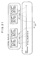
- PlayItem1, PlayItem2, PlayItem3 and PlayItem4 which are included in Virtual PlayList, reference this DVF-sequence.
- the AV stream data be deleted from the DVF-sequence. The deleted the AV stream data is not referenced by any of PlayItem1, PlayItem2, PlayItem3 and PlayItem4 as shown in Fig. 21 .
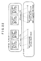
- the DVF-sequence is split into DVF-sequence#0 and DVF-sequence#1 as shown in Fig. 22 .
- Clip after the editing work has two DVF-sequences. Offset_FN_DVF [0] of the first DVF-sequence is set at 0 and Offset_FN_DVF [1] of the second DVF-sequence is set at a value X.
- the value X is greater than OUT_time2 but smaller than or equal to IN_time 3.
- the reproduction unit is capable of finding a DVF-sequence pointed to by IN_time and OUT_time, which are included in PlayItem, by comparing IN_time with Offset_FN_DVF of each DVF-sequence.
- the second DVF-sequence is known as a sequence pointed to by IN_time3 and OUT_time3, which are included in PlayItem3.
- a program-sequence in an AV stream file is an array of frames in which the contents of a program prescribed in this format are fixed.
- Fig. 23 is an explanatory diagram used for describing a program-sequence.
- a frame number assigned to a frame at the beginning of a new program-sequence in an AV stream file is stored in ProgramInfo ( ). This frame number is denoted by FN_program_sequence_start.
- all program-sequences other than the last program-sequence each begin with a frame pointed to by FN_program_sequence_start and end with a frame immediately preceding a frame indicated by next FN_program_sequence_start.
- the last program-sequence begins with a frame indicated by SPN_program_sequence_start and ends with the last frame of the AV stream file.
- the AV stream file comprises 2 program-sequences, namely, program-sequence #0 and program-sequence #1.
- a program-sequence may be spread over DVF-sequences, crossing boundaries between the DVF-sequences.
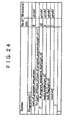
- Fig. 24 is a diagram showing the syntax of ProgramInfo ( ). num_of_program_sequences is the number of program-sequences included in the AV stream file.
- FN_program_sequence_start [pgm_id] is a frame number assigned to a DV frame at the beginning of a program-sequence in an AV stream file.
- audio_mode [pgm_id] is the audio mode of the DV signal.
- the mode can be a 48 kHz mode, a 44.1 kHz mode or a 32 kHz-2CH mode.
- lock_flag [pgm_id] is a flag indicating whether or not the video and audio signals are locked.
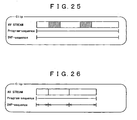
- Fig. 25 is a diagram showing data of one Clip AV stream.
- the Clip AV stream has one program-sequence and one DVF-sequence. The contents of the program-sequence do not change.
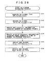
- Fig. 26 is a diagram showing data of the Clip AV stream. The data is a result of an operation to delete portions each indicated by a hatched block from the data of the Clip AV stream shown in Fig. 25 in an editing work.
- Clip shown in Fig. 26 has 3 DVF-sequences but the program-sequence remains as a single program-sequence as it is. In this case, the program-sequence is spread over the DVF-sequences, crossing boundaries between the DVF-sequences.
- Fig. 27 is a block diagram showing a typical configuration of a DV recording/reproducing apparatus 1.
- the DV recording/reproducing apparatus 1 comprises a recording unit 2 for recording data and a reproduction unit 3 for reproducing data.
- An AV signal received from a terminal 28 is encoded in a DV encoding unit 18 to obtain a DV stream.
- a DV stream is obtained from a terminal 29 by way of an IEEE 1394 I/F 19.
- a DV stream analyzing unit 20 analyzes the DV stream before temporarily storing the stream in a buffer 21.
- An ECC (Error-Correcting Code) encoding unit 22 adds ECC codes to the AV stream read out from the buffer 21 and then supplies the AV stream including the additional ECC codes to a modulation unit 23, which modulates the stream and then outputs a result of the modulation to a write unit 24.
- the write unit 24 then records an AV stream file onto a recording medium 10 in accordance with a control signal generated by a control unit 17.
- the DV recording/reproducing apparatus 1 stores not only an AV stream file onto the recording medium 10 as described above, but also application database information related to the file.
- the application database information is generated in the control unit 17 on the basis of input information received by the control unit 17 from the DV stream analyzing unit 20 and in accordance with an input command received from a terminal 27.
- the information received from the DV stream analyzing unit 20 includes the type (DV_format_type) of the DV signal, the number of input DV frames and program information.
- the number of frames at the end of the operation to record the DV stream onto the recording medium 10 is the number of frames (Number_of_frames) included in a DVF-sequence.
- Information on changes in program contents included in the AV stream is data stored in ProgramInfo.
- the information received from the DV stream analyzing unit 20 is stored in a database (Clip information) of the AV stream.
- a command received from the terminal 27 includes information specifying a reproduction section in the AV stream, a string of characters explaining the contents of the reproduction section, a bookmark to be set in a scene specified by the user and a timestamp corresponding to a resume point in the AV stream. These pieces of information included in the command entered by the user are stored in the database of PlayList.
- the control unit 17 On the basis of the input information described above, the control unit 17 generates a database (Clip information) of the AV stream, a database of PlayList and management information (info.dvr) for data being recorded onto the recording medium 10. These pieces of database information are subjected to the processes carried out by the ECC encoding unit 22 and the modulation unit 23 in the same way as the AV stream before being supplied to the write unit 24.
- the write unit 24 then stores database files onto the recording medium 10 in accordance with a control signal received from the control unit 17.
- the control unit 17 issues a request to a read unit 11 to read out application database information from the recording medium 10.
- the read unit 11 reads out the application database information from the recording medium 10.
- the read unit 11 supplies the application database information to a demodulation unit 12, which then demodulates the information.
- the demodulation unit 12 supplies demodulated information to an ECC (Error-Correcting Code) decoding unit 13, which then carries out an error correction process on the information.
- ECC Error-Correcting Code
- the control unit 17 outputs a list of PlayList objects based on the application database to a user interface by way of a terminal 27.
- the user interface lets the user select PlayList to be reproduced from the list of PlayList objects.
- the control unit 17 issues a request to the read unit 11 to read out an AV stream file required in reproduction of selected PlayList from the recording medium 10.
- the read unit 11 reads out the AV stream file from the recording medium 10.
- a reproduced DV stream file is supplied to a buffer 14.
- the control unit 17 then executes control so as to read out a stream comprising DV frames for a reproduction section (PlayItem) of the AV stream from the buffer 14.
- the data of the DV frames read out from the buffer 14 is then supplied to a DV decoding unit 15.
- the DV decoding unit 15 decodes the data of the DV frames and outputs a reproduced AV signal to a terminal 26.
- the data of the DV frames read out from the buffer 14 is also output to a terminal 25 as a DV stream by way of an IEEE 1394 I/F 16.
- the IN and OUT points of a reproduction section are extracted from a UI (User Interface) input received from the terminal 27 and are then supplied to the control unit 17.
- the control unit 17 then creates a database of PlayList to be used as a group of reproduction sections (PlayItem objects) of an AV stream.
- the control unit 17 changes the database of PlayList so that only necessary portions of the AV stream are referenced. Then, the control unit 17 issues a request to the write unit 24 to delete the unnecessary portion of the AV stream.
- the contents of the Clip information file are also updated to reflect the change in the Clip AV stream.
- UI User Interface
- the control unit 17 acquires the type (DV_format_type) of a DV signal from the DV stream analyzing unit 20.
- DV_format_type may indicate an SD-DVCR 525-60 system with a byte count of 120,000 bytes, an SD-DVCR 625-50 system with a byte count of 144,000 bytes, an SDL-DVCR 525-60 system with a byte count of 60,000 bytes or an SDL-DVCR 625-50 system with a byte count of 72,000 bytes.
- control unit 17 controls the write unit 24 to record the Clip AV stream file onto the recording medium 10.
- the control unit 17 creates DVF-sequence information.
- the total number of recorded frames is acquired from the DV stream analyzing unit 20.
- the control unit 17 sets the total number of recorded frames acquired from the DV stream analyzing unit 20 as Number_of_frames.
- the control unit 17 creates program-sequence information. To put it concretely, the control unit 17 acquires a frame number at the time of change in program contents is made. The frame number is stored in ProgramInfo. In the case of the example shown in Fig. 23 , there are 2 program-sequences, namely, program-sequence #0 and program-sequence #1. In the case of the example shown in Fig. 26 , on the other hand, there is only 1 program-sequence.
- the control unit 17 creates a Clip information file for the Clip AV stream file recorded onto the recording medium 10 at the step S12 and records the Clip information file onto the recording medium 10.
- the Clip information file is a database file for managing time-base information along the AV stream and data contained in the Clip AV stream file.
- the control unit 17 creates a Real PlayList file covering the entire reproduction range of Clip and records the file onto the recording medium 10.
- Real PlayList specifies an access point in Clip mainly as a timestamp.
- control unit 17 receives a command entered by the user to reproduce PlayList.
- the control unit 17 acquires IN_time of present PlayItem. If the command received at the step S31 is a command to reproduce PlayList for a DVF-sequence of Clip A like the one shown in Fig. 21 , for example, the control unit 17 acquires IN_time1 of present PlayItem1.
- control unit 17 acquires the address of a frame referenced by IN_time.
- the processing carried out at this step is explained in detail as follows.
- the control unit 17 compares IN_time with Offset_FN_DVF of each of N DVF-sequences. Offset_FN_DVF of each of N DVF-sequences is included in SequenceInfo of Clip referenced by IN_time. (In the case of the example shown in Fig. 21 , IN_time is IN_time1 and Clip is Clip A). Then, the control unit 17 finds a minimum k that has a value in the range 0 ⁇ k ⁇ N and satisfies Eq. (5) as follows. Offset_FN_DVF k ⁇ IN_time
- a frame referenced by IN_time is included in the kth DVF-sequence of Clip.
- the control unit 17 then computes the address of a predetermined frame in the AV stream file as the address of the frame referenced by IN_time.
- the address of the perdetermined frame referenced by IN_time is the number of bytes between the beginning of the AV stream file and the perdetermined frame.
- control unit 17 controls the read unit 11 to read out data of the AV stream from the address computed at the step S33 and supply the data to the DV decoding unit 15.
- control unit 17 drives the DV decoding unit 15 to decode and reproduce the AV stream.
- the control unit 17 determins as to whether or not the processing to reproduce a frame referenced by OUT_time (in the case of the example shown in Fig. 21 , OUT_time1) has been completed. If the outcome of the determination indicates that the processing to reproduce the frame referenced by OUT_time has not been completed, the flow of the process goes back to the step S35 to repeat the process from the step.
- step S36 If the outcome of the determination at the step S36 indicates that the processing to reproduce the frame referenced by OUT_time (in the case of the example shown in Fig. 21 , OUT_time1) has been completed, the flow of the process goes on to a step S37 at which the control unit 17 determines as to whether or not the processing to reproduce last PlayItem (in the case of the example shown in Fig. 21 , PlayItem4) has been completed. If the outcome of the judgment indicates that the processing to reproduce last PlayItem has not been completed, the flow of the process goes back to the step S32 to repeat the process from the step.
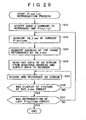
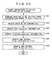
- the control unit 17 acquires sections to be deleted from a reproduction range of Real Playlist.
- the control unit 17 deletes the AV stream data of Clip referenced by the acquired reproduction sections to be deleted.
- the control unit 17 deletes the AV stream data of Clip referenced by the reproduction section DTA to be deleted.
- the control unit 17 updates the DVF-sequence information to reflect an AV stream file obtained as a result of the deletion of the data.
- the DVF-sequence is split into DVF-sequence#0 and DVF-sequence#1 as shown in Fig. 17 .
- the control unit 17 updates Offset_FN_DVF, Num_of_frames Leading_data_size and Trailing_data_size, which are included in DVF-sequence information shown in Fig. 19 .
- SECTOR_SIZE Trailing_data_size tds where symbol % is an operator for finding a division remainder.
- Notation SECTOR_SIZE denotes the number of bytes composing a sector. A typical value of SECTOR_SIZE is 2,048.
- the number of sectors containing the deleted data starting from the beginning of the DVF-sequence is expressed by the following expression: offset_x / SECTOR_SIZE.
- Trailing_data_size is computed as follows. First of all, offset_y, which denotes the number of bytes existing between the beginning of the DVF-sequence and a frame indicated by the frame number y, is computed by using Eqs. (24) to (27) as follows.
- Trailing_data_size 0
- the control unit 17 updates the Clip information file to reflect results of the processing carried out at the steps S53 and S54, recording the updated Clip information file.
- the control unit 17 updates the Real PlayList file to reflect changes in reproduction range, which have been made at the step S51, and stores the updated Real PlayList file.
- a DV stream is taken as an example of the AV stream. It is to be noted, however, that the example of the AV stream is not limited to a DV stream.
- the present invention can be applied to any other stream as long as the number of bytes composing each video frame of the other stream is fixed.
- data can be recorded, deleted and reproduced onto and from a disc in units other than sectors.
- a DVF-sequence is defined as an array of bytes composing DV frames having regularly increasing frame numbers assigned thereto.
- the definition can also be changed to an array of DV bytes composing frames with regularly increasing reproduction times.
- the reproduction time is expressed as a value obtained by multiplying the frame number by 3,003, which is a number for the 525-60 system.
- the value is obtained by multiplying the frame number by 3,003, which is a number for the 525-60 system.
- the axis representing the frame number in Figs. 12 , 16 and 18 is replaced by an axis representing the reproduction time.
- Offset_FN_DVF in the syntax of SequenceInfo FN_program_sequence_start of ProgramInfo as well as IN_time and OUT_time in the syntax of PlayItem may be expressed by a reproduction time in place of a frame number.
- the reproduction time is expressed as a value obtained by multiplying the frame number by 3,003, which is a number for the 525-60 system.
- offset_x DVF_sequence_size 0 + lds ⁇ 1 + time_x - time_ofn ⁇ 1 / FT ⁇ FS
- notation time_x denotes the reproduction start time of the xth frame
- notation time_ofn1 denotes an offset reproduction start time of a frame array including the xth frame
- notation FT denotes the reproduction time of one frame.
- FT has a value of 3,003.
- Offset_FN_DVF and Number_of_frames which are described in the syntax of SequenceInfo
- data included in portions indicated by Leading_data_size and Trailing_data_size is not limited to data of an incomplete frame. Instead, data included in such portions may be any kind of data. For example, data of a complete DV frame or database information may be included in the portions.
- the present invention is not limited to this scheme.
- the amount of data included in the leading portion may exceed the length of one sector as shown in Fig. 31 . This flexibility is also applicable to the amount of data included in a trailing portion.
- the amount of data included in the leading portion and the amount of data included in the trailing portion can be limited to the following value.
- the amount of data included in the leading portion is limited to a multiple of 64 bytes for the SD-DVCR 525-60 system or a multiple of 128 bytes for the SD-DVCR 625-50 system.
- the amount of data included in the trailing portion is limited to a multiple of 64 bytes for the SD-DVCR 525-60 system or a multiple of 128 bytes for the SD-DVCR 625-50 system.
- the number 64 is the greatest common divisor of a sector size of 2,048 bytes and a DV frame size of 120,000 bytes for the SD-DVCR 525-60 system.
- the number 128 is the greatest common divisor of a sector size of 2,048 bytes and a DV frame size of 144,000 bytes for the SD-DVCR 625-50 system.
- an inter-frame differential encoding process is not carried out. This is because all frames are each regarded as an intra frame, which is a frame to be subjected to an intra-frame encoding process. Thus, a DV stream can be cut or connected to another DV stream on a frame boundary without losing decoding continuities.
- information is managed by using Clip information files separated from each other and PlayList files also separated from each other.
- the Clip information files can be combined into a single file.
- the PlayList files can be combined into a single file.
- data can be managed in any format if the format is manageable to a moving-picture recording/reproducing apparatus.
- the recorded information includes an offset frame number (Offset_FN_DVF) or offset reproduction start time of the first DV frame of the DVF-sequence in the recorded DV stream.
- the recording medium also includes the number of DV frames (Number_of_frames) included in the DVF-sequence.
- a continuously recorded DV frame array does not include a point of discontinuity in the series of regularly increasing frame numbers or reproduction times, and only one DFV-sequence exists. This DVF-sequence starts with the first frame of the DV frame array.
- a process such as an editing work causes data of an unnecessary reproduction section to be deleted from the DV frame array and puts together all the remaining data in a new single data file.
- a plurality of DVF-sequences can exist in the new data file.
- an offset frame number or offset reproduction start time of each DVF-sequence to be reproduced as the first DV frame for the DVF-sequence is also recorded onto the recording medium.
- Leading_data_size, Trailing_data_size and Number_of_frames are also recorded onto the recording medium for each of the DVF-sequences.
- Leading_data_size for a DVF-sequence is the number of bytes in data preceding a DV frame to be reproduced as the first DV frame for the DVF-sequence.
- Trailing_data_size for a DVF-sequence is the number of bytes in data succeeding a DV frame to be reproduced as the last DV frame for the DVF-sequence.
- Number_of_frames for a DVF-sequence is the number of frames included in the DVF-sequence.
- a point of a change in program contents of a DV stream is detected, and information (program-sequence) of a DV frame array having continuous program contents is recorded on the recording medium.
- information (program-sequence) of a DV frame array having continuous program contents is recorded on the recording medium.
- a reproduction start time or a frame number assigned to a DV frame at which the program-sequence starts in a recorded DV stream is recorded onto the recording medium.
- the program-sequence may be spread over a plurality of DVF-sequences, crossing boundaries of the DVF-sequences.
- the reproduction start and end times of the AV data can be managed properly. Since a target reproduction start time in a file can be found with ease in a reproduction process based on a random access, it is possible to implement the reproduction process based on a random access as a reproduction process having a fast response to an input entered by the user.
- IEEE 1394 I/F is used in the embodiment described above as a digital interface, it is needless to say that another interface such as the USB can also be adopted as well.
- the series of processes described above can be carried out by using hardware or software. If the series of processes is to be carried out by using software, programs composing the software are installed in a computer embedded in special-purpose hardware or another computer such as a general-purpose personal computer from a program storage medium.
- the program storage medium from which the programs composing the software are to be installed is package media distributed to users separately from the computer to present the programs to the users.
- Examples of the package media containing the programs are a magnetic disc 41 including a floppy disc, an optical disc 42 including a CD-ROM (Compact Disc-Read Only Memory) and a DVD (Digital Versatile Disc), a magneto-optical disc 43 including an MD (Mini Disc,) and a semiconductor memory 44, which are shown in Fig. 27 .
- the programs can also be stored in advance in either of a ROM and a hard disc, which are components embedded in the computer. In this way, the programs are presented to the user in a state of being embedded in the computer in advance. It is to be noted that the embedded ROM and the embedded hard disc themselves are shown in none of the figures.
- steps prescribing a computer program of course represent processes to be carried out in an order the steps are described along the time base. It is to be noted, however, that the steps do not necessarily represent such sequential processes. Instead, the steps may represent processes including those to be carried out concurrently or individually.
- system used in the description means an entire apparatus combination comprising a plurality of apparatus.
- a reproduction position can be identified.
- the reproduction position can be identified fast and with a high degree of reliability.
Applications Claiming Priority (3)
| Application Number | Priority Date | Filing Date | Title |
|---|---|---|---|
| JP2002100349 | 2002-04-02 | ||
| JP2002100349 | 2002-04-02 | ||
| PCT/JP2003/003796 WO2003083868A1 (fr) | 2002-04-02 | 2003-03-27 | Dispositif et procede d'enregistrement de donnees, dispositif et procede de lecture de donnees, support d'enregistrement d'informations, support de programme et programme |
Publications (3)
| Publication Number | Publication Date |
|---|---|
| EP1492115A1 EP1492115A1 (en) | 2004-12-29 |
| EP1492115A4 EP1492115A4 (en) | 2009-06-10 |
| EP1492115B1 true EP1492115B1 (en) | 2012-06-06 |
Family
ID=28672032
Family Applications (1)
| Application Number | Title | Priority Date | Filing Date |
|---|---|---|---|
| EP03715478A Expired - Lifetime EP1492115B1 (en) | 2002-04-02 | 2003-03-27 | Data recording device and method, data reproduction device and method, information recording medium, program-containing medium, and program |
Country Status (10)
| Country | Link |
|---|---|
| US (1) | US7496824B2 (zh) |
| EP (1) | EP1492115B1 (zh) |
| JP (1) | JP4423972B2 (zh) |
| KR (1) | KR100930252B1 (zh) |
| CN (1) | CN100347783C (zh) |
| AU (1) | AU2003227249B2 (zh) |
| CA (1) | CA2449067C (zh) |
| ES (1) | ES2389035T3 (zh) |
| TW (1) | TWI248605B (zh) |
| WO (1) | WO2003083868A1 (zh) |
Families Citing this family (3)
| Publication number | Priority date | Publication date | Assignee | Title |
|---|---|---|---|---|
| PL2207182T3 (pl) * | 2004-04-28 | 2012-09-28 | Panasonic Corp | Urządzenie do generowania strumienia ruchomego obrazu, urządzenie do kodowania ruchomego obrazu, urządzenie do multipleksowania ruchomego obrazu oraz urządzenie do dekodowania ruchomego obrazu |
| JP4862138B2 (ja) * | 2007-02-28 | 2012-01-25 | 株式会社Jvcケンウッド | 記録再生システム、記録再生装置及び制御装置 |
| US8744186B1 (en) * | 2011-09-30 | 2014-06-03 | Tribune Broadcasting Company, Llc | Systems and methods for identifying a scene-change/non-scene-change transition between frames |
Family Cites Families (12)
| Publication number | Priority date | Publication date | Assignee | Title |
|---|---|---|---|---|
| US6181679B1 (en) * | 1993-03-19 | 2001-01-30 | International Business Machines Corporation | Management of packet transmission networks |
| JP3157366B2 (ja) | 1993-08-31 | 2001-04-16 | 三洋電機株式会社 | 立体動画記録装置、立体動画再生装置、及び立体動画送出装置 |
| JPH07212704A (ja) * | 1994-01-18 | 1995-08-11 | Matsushita Electric Ind Co Ltd | ノンリニアav編集装置 |
| JP3309656B2 (ja) | 1995-08-18 | 2002-07-29 | ソニー株式会社 | 画像処理装置及び画像処理方法 |
| JP3050311B2 (ja) | 1997-09-17 | 2000-06-12 | 松下電器産業株式会社 | 光ディスク、記録装置及び再生装置 |
| EP0903744B1 (en) * | 1997-09-17 | 2001-01-10 | Matsushita Electric Industrial Co., Ltd | Optical disc, video data editing apparatus, computer-readable recording medium storing an editing program, reproduction apparatus for the optical disc, and computer-readable recording medium storing a reproduction program |
| JPH11176083A (ja) | 1997-12-12 | 1999-07-02 | Hitachi Ltd | 画像音声記録再生装置 |
| JP2001273716A (ja) * | 2000-01-21 | 2001-10-05 | Sharp Corp | データ再生方法 |
| JP4719957B2 (ja) * | 2000-05-24 | 2011-07-06 | 株式会社日立製作所 | 記憶制御装置及び記憶システム並びに記憶システムのセキュリティ設定方法 |
| US6907044B1 (en) * | 2000-08-04 | 2005-06-14 | Intellon Corporation | Method and protocol to support contention-free intervals and QoS in a CSMA network |
| US6987770B1 (en) * | 2000-08-04 | 2006-01-17 | Intellon Corporation | Frame forwarding in an adaptive network |
| KR100743820B1 (ko) * | 2000-09-29 | 2007-07-30 | 마쯔시다덴기산교 가부시키가이샤 | 압축 오디오 데이터 편집 및 재생 방법 |
-
2003
- 2003-03-27 EP EP03715478A patent/EP1492115B1/en not_active Expired - Lifetime
- 2003-03-27 CN CNB038003643A patent/CN100347783C/zh not_active Expired - Lifetime
- 2003-03-27 WO PCT/JP2003/003796 patent/WO2003083868A1/ja active Application Filing
- 2003-03-27 US US10/479,449 patent/US7496824B2/en active Active
- 2003-03-27 JP JP2003581201A patent/JP4423972B2/ja not_active Expired - Lifetime
- 2003-03-27 ES ES03715478T patent/ES2389035T3/es not_active Expired - Lifetime
- 2003-03-27 CA CA2449067A patent/CA2449067C/en not_active Expired - Fee Related
- 2003-03-27 AU AU2003227249A patent/AU2003227249B2/en not_active Expired
- 2003-03-27 KR KR1020037014853A patent/KR100930252B1/ko not_active IP Right Cessation
- 2003-04-02 TW TW092107524A patent/TWI248605B/zh not_active IP Right Cessation
Also Published As
| Publication number | Publication date |
|---|---|
| US7496824B2 (en) | 2009-02-24 |
| CN100347783C (zh) | 2007-11-07 |
| AU2003227249A1 (en) | 2003-10-13 |
| ES2389035T3 (es) | 2012-10-22 |
| CN1515009A (zh) | 2004-07-21 |
| CA2449067A1 (en) | 2003-10-09 |
| US20040153948A1 (en) | 2004-08-05 |
| JPWO2003083868A1 (ja) | 2005-08-04 |
| TWI248605B (en) | 2006-02-01 |
| AU2003227249B2 (en) | 2009-05-28 |
| EP1492115A4 (en) | 2009-06-10 |
| EP1492115A1 (en) | 2004-12-29 |
| CA2449067C (en) | 2012-07-24 |
| WO2003083868A1 (fr) | 2003-10-09 |
| TW200405285A (en) | 2004-04-01 |
| JP4423972B2 (ja) | 2010-03-03 |
| KR100930252B1 (ko) | 2009-12-09 |
| KR20040094290A (ko) | 2004-11-09 |
Similar Documents
| Publication | Publication Date | Title |
|---|---|---|
| EP1103974B1 (en) | Recording/reproduction apparatus and method as well as recording medium | |
| US6181870B1 (en) | Optical disc having an area storing original and user chain information specifying at least part of a video object stored on the disc, and a computer program and recording apparatus for recording and editing the chain information | |
| KR100795255B1 (ko) | 정보 처리 장치 및 방법, 프로그램과 기록 매체 | |
| KR100942751B1 (ko) | 데이터 기록 장치 및 방법, 프로그램 저장 매체 | |
| KR100880086B1 (ko) | 정보 기록 장치 및 방법, 정보 재생 장치 및 방법, 정보 기록 매체, 및 프로그램 기록 매체 | |
| WO2001082609A1 (fr) | Appareil et procede d'enregistrement, appareil et procede de reproduction, support enregistre et programme | |
| WO2003001801A1 (en) | Data transmitting device and method | |
| US6487364B2 (en) | Optical disc, video data editing apparatus, computer-readable recording medium storing an editing program, reproduction apparatus for the optical disc, and computer-readable recording medium storing a reproduction program | |
| EP1492115B1 (en) | Data recording device and method, data reproduction device and method, information recording medium, program-containing medium, and program | |
| JP4462799B2 (ja) | 情報記録装置および方法、情報再生装置および方法、情報記録媒体、プログラム格納媒体、並びにプログラム | |
| JP4672681B2 (ja) | 情報記録装置および方法、情報再生装置および方法、並びに情報記録媒体 |
Legal Events
| Date | Code | Title | Description |
|---|---|---|---|
| PUAI | Public reference made under article 153(3) epc to a published international application that has entered the european phase |
Free format text: ORIGINAL CODE: 0009012 |
|
| 17P | Request for examination filed |
Effective date: 20031203 |
|
| AK | Designated contracting states |
Kind code of ref document: A1 Designated state(s): AT BE BG CH CY CZ DE DK EE ES FI FR GB GR HU IE IT LI LU MC NL PT RO SE SI SK TR |
|
| AX | Request for extension of the european patent |
Extension state: AL LT LV MK |
|
| A4 | Supplementary search report drawn up and despatched |
Effective date: 20090511 |
|
| RIC1 | Information provided on ipc code assigned before grant |
Ipc: G11B 20/10 20060101ALI20090505BHEP Ipc: G11B 20/12 20060101ALI20090505BHEP Ipc: G11B 27/10 20060101ALI20090505BHEP Ipc: G11B 27/32 20060101ALI20090505BHEP Ipc: G11B 27/034 20060101AFI20031016BHEP |
|
| 17Q | First examination report despatched |
Effective date: 20100415 |
|
| GRAP | Despatch of communication of intention to grant a patent |
Free format text: ORIGINAL CODE: EPIDOSNIGR1 |
|
| RBV | Designated contracting states (corrected) |
Designated state(s): DE ES FR GB IT NL |
|
| GRAS | Grant fee paid |
Free format text: ORIGINAL CODE: EPIDOSNIGR3 |
|
| GRAA | (expected) grant |
Free format text: ORIGINAL CODE: 0009210 |
|
| AK | Designated contracting states |
Kind code of ref document: B1 Designated state(s): DE ES FR GB IT NL |
|
| REG | Reference to a national code |
Ref country code: GB Ref legal event code: FG4D |
|
| REG | Reference to a national code |
Ref country code: DE Ref legal event code: R096 Ref document number: 60341142 Country of ref document: DE Effective date: 20120802 |
|
| REG | Reference to a national code |
Ref country code: NL Ref legal event code: T3 |
|
| REG | Reference to a national code |
Ref country code: ES Ref legal event code: FG2A Ref document number: 2389035 Country of ref document: ES Kind code of ref document: T3 Effective date: 20121022 |
|
| PLBE | No opposition filed within time limit |
Free format text: ORIGINAL CODE: 0009261 |
|
| STAA | Information on the status of an ep patent application or granted ep patent |
Free format text: STATUS: NO OPPOSITION FILED WITHIN TIME LIMIT |
|
| 26N | No opposition filed |
Effective date: 20130307 |
|
| REG | Reference to a national code |
Ref country code: DE Ref legal event code: R097 Ref document number: 60341142 Country of ref document: DE Effective date: 20130307 |
|
| REG | Reference to a national code |
Ref country code: FR Ref legal event code: PLFP Year of fee payment: 14 |
|
| REG | Reference to a national code |
Ref country code: FR Ref legal event code: PLFP Year of fee payment: 15 |
|
| REG | Reference to a national code |
Ref country code: FR Ref legal event code: PLFP Year of fee payment: 16 |
|
| PGFP | Annual fee paid to national office [announced via postgrant information from national office to epo] |
Ref country code: GB Payment date: 20220225 Year of fee payment: 20 Ref country code: DE Payment date: 20220217 Year of fee payment: 20 |
|
| PGFP | Annual fee paid to national office [announced via postgrant information from national office to epo] |
Ref country code: NL Payment date: 20220217 Year of fee payment: 20 Ref country code: IT Payment date: 20220217 Year of fee payment: 20 Ref country code: FR Payment date: 20220221 Year of fee payment: 20 |
|
| PGFP | Annual fee paid to national office [announced via postgrant information from national office to epo] |
Ref country code: ES Payment date: 20220401 Year of fee payment: 20 |
|
| REG | Reference to a national code |
Ref country code: DE Ref legal event code: R071 Ref document number: 60341142 Country of ref document: DE |
|
| REG | Reference to a national code |
Ref country code: NL Ref legal event code: MK Effective date: 20230326 |
|
| REG | Reference to a national code |
Ref country code: GB Ref legal event code: PE20 Expiry date: 20230326 |
|
| REG | Reference to a national code |
Ref country code: ES Ref legal event code: FD2A Effective date: 20230426 |
|
| PG25 | Lapsed in a contracting state [announced via postgrant information from national office to epo] |
Ref country code: GB Free format text: LAPSE BECAUSE OF EXPIRATION OF PROTECTION Effective date: 20230326 |
|
| P01 | Opt-out of the competence of the unified patent court (upc) registered |
Effective date: 20230527 |
|
| PG25 | Lapsed in a contracting state [announced via postgrant information from national office to epo] |
Ref country code: ES Free format text: LAPSE BECAUSE OF EXPIRATION OF PROTECTION Effective date: 20230328 |