EP1491826A1 - Air conditioner - Google Patents
Air conditioner Download PDFInfo
- Publication number
- EP1491826A1 EP1491826A1 EP03745406A EP03745406A EP1491826A1 EP 1491826 A1 EP1491826 A1 EP 1491826A1 EP 03745406 A EP03745406 A EP 03745406A EP 03745406 A EP03745406 A EP 03745406A EP 1491826 A1 EP1491826 A1 EP 1491826A1
- Authority
- EP
- European Patent Office
- Prior art keywords
- indoor
- room temperature
- temperature monitoring
- control unit
- unit
- Prior art date
- Legal status (The legal status is an assumption and is not a legal conclusion. Google has not performed a legal analysis and makes no representation as to the accuracy of the status listed.)
- Granted
Links
Images


Classifications
-
- F—MECHANICAL ENGINEERING; LIGHTING; HEATING; WEAPONS; BLASTING
- F25—REFRIGERATION OR COOLING; COMBINED HEATING AND REFRIGERATION SYSTEMS; HEAT PUMP SYSTEMS; MANUFACTURE OR STORAGE OF ICE; LIQUEFACTION SOLIDIFICATION OF GASES
- F25B—REFRIGERATION MACHINES, PLANTS OR SYSTEMS; COMBINED HEATING AND REFRIGERATION SYSTEMS; HEAT PUMP SYSTEMS
- F25B13/00—Compression machines, plants or systems, with reversible cycle
-
- F—MECHANICAL ENGINEERING; LIGHTING; HEATING; WEAPONS; BLASTING
- F24—HEATING; RANGES; VENTILATING
- F24F—AIR-CONDITIONING; AIR-HUMIDIFICATION; VENTILATION; USE OF AIR CURRENTS FOR SCREENING
- F24F11/00—Control or safety arrangements
- F24F11/30—Control or safety arrangements for purposes related to the operation of the system, e.g. for safety or monitoring
- F24F11/46—Improving electric energy efficiency or saving
-
- F—MECHANICAL ENGINEERING; LIGHTING; HEATING; WEAPONS; BLASTING
- F24—HEATING; RANGES; VENTILATING
- F24F—AIR-CONDITIONING; AIR-HUMIDIFICATION; VENTILATION; USE OF AIR CURRENTS FOR SCREENING
- F24F11/00—Control or safety arrangements
- F24F11/62—Control or safety arrangements characterised by the type of control or by internal processing, e.g. using fuzzy logic, adaptive control or estimation of values
-
- F—MECHANICAL ENGINEERING; LIGHTING; HEATING; WEAPONS; BLASTING
- F24—HEATING; RANGES; VENTILATING
- F24F—AIR-CONDITIONING; AIR-HUMIDIFICATION; VENTILATION; USE OF AIR CURRENTS FOR SCREENING
- F24F11/00—Control or safety arrangements
- F24F11/50—Control or safety arrangements characterised by user interfaces or communication
- F24F11/54—Control or safety arrangements characterised by user interfaces or communication using one central controller connected to several sub-controllers
-
- F—MECHANICAL ENGINEERING; LIGHTING; HEATING; WEAPONS; BLASTING
- F24—HEATING; RANGES; VENTILATING
- F24F—AIR-CONDITIONING; AIR-HUMIDIFICATION; VENTILATION; USE OF AIR CURRENTS FOR SCREENING
- F24F2110/00—Control inputs relating to air properties
- F24F2110/10—Temperature
-
- F—MECHANICAL ENGINEERING; LIGHTING; HEATING; WEAPONS; BLASTING
- F24—HEATING; RANGES; VENTILATING
- F24F—AIR-CONDITIONING; AIR-HUMIDIFICATION; VENTILATION; USE OF AIR CURRENTS FOR SCREENING
- F24F2140/00—Control inputs relating to system states
- F24F2140/20—Heat-exchange fluid temperature
-
- F—MECHANICAL ENGINEERING; LIGHTING; HEATING; WEAPONS; BLASTING
- F25—REFRIGERATION OR COOLING; COMBINED HEATING AND REFRIGERATION SYSTEMS; HEAT PUMP SYSTEMS; MANUFACTURE OR STORAGE OF ICE; LIQUEFACTION SOLIDIFICATION OF GASES
- F25B—REFRIGERATION MACHINES, PLANTS OR SYSTEMS; COMBINED HEATING AND REFRIGERATION SYSTEMS; HEAT PUMP SYSTEMS
- F25B2313/00—Compression machines, plants or systems with reversible cycle not otherwise provided for
- F25B2313/023—Compression machines, plants or systems with reversible cycle not otherwise provided for using multiple indoor units
- F25B2313/0232—Compression machines, plants or systems with reversible cycle not otherwise provided for using multiple indoor units with bypasses
-
- F—MECHANICAL ENGINEERING; LIGHTING; HEATING; WEAPONS; BLASTING
- F25—REFRIGERATION OR COOLING; COMBINED HEATING AND REFRIGERATION SYSTEMS; HEAT PUMP SYSTEMS; MANUFACTURE OR STORAGE OF ICE; LIQUEFACTION SOLIDIFICATION OF GASES
- F25B—REFRIGERATION MACHINES, PLANTS OR SYSTEMS; COMBINED HEATING AND REFRIGERATION SYSTEMS; HEAT PUMP SYSTEMS
- F25B2313/00—Compression machines, plants or systems with reversible cycle not otherwise provided for
- F25B2313/023—Compression machines, plants or systems with reversible cycle not otherwise provided for using multiple indoor units
- F25B2313/0233—Compression machines, plants or systems with reversible cycle not otherwise provided for using multiple indoor units in parallel arrangements
-
- F—MECHANICAL ENGINEERING; LIGHTING; HEATING; WEAPONS; BLASTING
- F25—REFRIGERATION OR COOLING; COMBINED HEATING AND REFRIGERATION SYSTEMS; HEAT PUMP SYSTEMS; MANUFACTURE OR STORAGE OF ICE; LIQUEFACTION SOLIDIFICATION OF GASES
- F25B—REFRIGERATION MACHINES, PLANTS OR SYSTEMS; COMBINED HEATING AND REFRIGERATION SYSTEMS; HEAT PUMP SYSTEMS
- F25B2313/00—Compression machines, plants or systems with reversible cycle not otherwise provided for
- F25B2313/029—Control issues
- F25B2313/0293—Control issues related to the indoor fan, e.g. controlling speed
-
- F—MECHANICAL ENGINEERING; LIGHTING; HEATING; WEAPONS; BLASTING
- F25—REFRIGERATION OR COOLING; COMBINED HEATING AND REFRIGERATION SYSTEMS; HEAT PUMP SYSTEMS; MANUFACTURE OR STORAGE OF ICE; LIQUEFACTION SOLIDIFICATION OF GASES
- F25B—REFRIGERATION MACHINES, PLANTS OR SYSTEMS; COMBINED HEATING AND REFRIGERATION SYSTEMS; HEAT PUMP SYSTEMS
- F25B2313/00—Compression machines, plants or systems with reversible cycle not otherwise provided for
- F25B2313/031—Sensor arrangements
- F25B2313/0314—Temperature sensors near the indoor heat exchanger
-
- F—MECHANICAL ENGINEERING; LIGHTING; HEATING; WEAPONS; BLASTING
- F25—REFRIGERATION OR COOLING; COMBINED HEATING AND REFRIGERATION SYSTEMS; HEAT PUMP SYSTEMS; MANUFACTURE OR STORAGE OF ICE; LIQUEFACTION SOLIDIFICATION OF GASES
- F25B—REFRIGERATION MACHINES, PLANTS OR SYSTEMS; COMBINED HEATING AND REFRIGERATION SYSTEMS; HEAT PUMP SYSTEMS
- F25B2700/00—Sensing or detecting of parameters; Sensors therefor
- F25B2700/21—Temperatures
- F25B2700/2104—Temperatures of an indoor room or compartment
-
- F—MECHANICAL ENGINEERING; LIGHTING; HEATING; WEAPONS; BLASTING
- F25—REFRIGERATION OR COOLING; COMBINED HEATING AND REFRIGERATION SYSTEMS; HEAT PUMP SYSTEMS; MANUFACTURE OR STORAGE OF ICE; LIQUEFACTION SOLIDIFICATION OF GASES
- F25B—REFRIGERATION MACHINES, PLANTS OR SYSTEMS; COMBINED HEATING AND REFRIGERATION SYSTEMS; HEAT PUMP SYSTEMS
- F25B2700/00—Sensing or detecting of parameters; Sensors therefor
- F25B2700/21—Temperatures
- F25B2700/2115—Temperatures of a compressor or the drive means therefor
- F25B2700/21152—Temperatures of a compressor or the drive means therefor at the discharge side of the compressor
Definitions
- the present invention relates to an air conditioner, and more particularly relates to a multi-room air conditioner wherein a plurality of indoor units is connected to a single outdoor unit.
- a so-called multi-room air conditioner wherein, in an air conditioner, a plurality of indoor units is connected to a single outdoor unit.
- a multi-room air conditioner can air condition a plurality of rooms.
- all indoor units are not necessarily operating continuously; some indoor units may be in operation, while the operation of other indoor units may be halted, or in a thermo-off state.
- the circulation of refrigerant is unnecessary in indoor units whose operation is halted or is in a thermo-off state.
- an air conditioner with a room temperature sensor, and a room temperature monitoring function that detects the indoor temperature.
- the room interior can thereby be controlled at a comfortable temperature by controlling each of the constituent apparatuses of the air conditioner.
- the room temperature sensor of the indoor unit in the thermo-off state it is known to detect the room temperature by taking the indoor air into the indoor unit.
- An indoor fan within the indoor unit in the thermo-off state is therefore driven during room temperature monitoring.
- the indoor temperature can thereby be detected more accurately.
- the air conditioner as recited in Claim 1 comprises a plurality of indoor units, an outdoor unit, and a room temperature monitoring control unit.
- Each indoor unit comprises a room temperature sensor; an indoor heat exchanger; an indoor fan; and an indoor control unit.
- the outdoor unit comprises an outdoor heat exchanger and constitutes a refrigerant circuit with the plurality of indoor units.
- the indoor control unit judges whether a start condition of room temperature monitoring is satisfied based on the room temperature sensor, and makes the indoor fan driven if performing room temperature monitoring when heating operation is in the thermo-off state.
- the room temperature monitoring control unit selects a prescribed indoor unit from the plurality of indoor units, and sends a room temperature monitoring enable-related signal to the indoor control unit of the selected indoor unit.
- the indoor control unit determines whether to perform room temperature monitoring based both on the signal and on the start condition of room temperature monitoring.
- the indoor control unit determines whether to perform room temperature monitoring based both on the signal received from the room temperature monitoring control unit, and the room temperature monitoring start condition. Consequently, the present air conditioner can limit the number of indoor units that simultaneously perform room temperature monitoring from the room temperature monitoring control unit. Accordingly, the number of simultaneously driven indoor fans can be limited. Thereby, the present air conditioner can accurately detect the indoor temperature, even in an indoor unit in the thermo-off state, while suppressing a precipitous drop in the blow-out temperature in the rooms in operation.
- the invention as recited in Claim 2 is the air conditioner as recited in Claim 1, wherein the signal is a room temperature monitoring enable signal that enables the performance of room temperature monitoring. Further, the indoor control unit performs room temperature monitoring if the room temperature monitoring enable signal is received and the start condition of room temperature monitoring is satisfied.
- room temperature monitoring is performed if the indoor control unit receives a room temperature monitoring enable signal and the room temperature monitoring start condition is satisfied. Consequently, even if a certain indoor control unit judges that the room temperature monitoring start condition is satisfied based on the conditions of the interior of that indoor unit, room temperature monitoring is not performed until the room temperature monitoring control unit enables room temperature monitoring. Accordingly, the number of indoor units that simultaneously perform room temperature monitoring can be limited from the room temperature monitoring control unit. Thereby, the present air conditioner can accurately detect the indoor temperature, even in an indoor unit in the thermo-off state, while suppressing a precipitous drop in the blow-out temperature in the rooms in operation.
- the invention as recited in Claim 3 is the air conditioner as recited in Claim 2, wherein the room temperature monitoring control unit sends the room temperature monitoring enable signal to each of the indoor control units staggered in time.
- the present air conditioner room temperature monitoring is not performed simultaneously for two or more indoor units because the room temperature monitoring enable signal is sent to each of the indoor control units staggered in time. Consequently, the present air conditioner can suppress a precipitous drop in the blow-out temperature in the rooms in operation.
- the invention as recited in Claim 4 is the air conditioner as recited in any one claim of Claim 1 through Claim 3, wherein the room temperature monitoring control unit sends the abovementioned signal to each of the indoor control units with equal timing.
- the room temperature monitoring control unit sends the signal to each of the indoor control units with equal timing. Consequently, an opportunity to perform room temperature monitoring is given equally to each of the indoor units. It is thereby possible to suppress biasing the number of times that room temperature monitoring is performed by each of the indoor units.
- the invention as recited in Claim 5 is the air conditioner as recited in any one claim of Claim 1 through Claim 4, wherein the room temperature monitoring control unit sends the abovementioned signal only to the indoor control units of the indoor units among the plurality of indoor control units wherein heating operation is in the thermo-off state.
- the room temperature monitoring control unit sends the signal only to the indoor control units of the indoor units wherein heating operation is in the thermo-off state. Consequently, the probability of an indoor unit losing an opportunity to perform monitoring is small compared with the case wherein a signal is sent to the indoor control units of all of the indoor units.
- the invention as recited in Claim 6 is the air conditioner as recited in any one claim of Claim 1 through Claim 4, wherein the room temperature monitoring control unit sends the signal to all of the indoor units.
- the room temperature monitoring control unit sends a signal to all of the indoor units. Consequently, the room temperature monitoring control unit does not need to judge whether the indoor unit is in the thermo-off state. The details of control are consequently simplified, lightening the burden placed on the room temperature monitoring control unit.
- FIG 1 depicts an air conditioner 1 that is used in one embodiment of the present invention.
- the air conditioner 1 is a so-called multi-room air conditioner, wherein a plurality of indoor units is connected to a single outdoor unit.
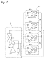
- FIG 2 depicts a schematic of the refrigerant circuit of the present air conditioner 1.
- the refrigerant circuit comprises a single outdoor unit 2, and four indoor units 3a, 3b, 3c, 3d connected in parallel to the outdoor unit 2.
- the indoor unit 3a comprises an indoor heat exchanger 30a, a motor-operated valve 31a, an indoor fan 32a, a room temperature thermistor 33a, and an indoor control unit 34a (refer to FIG. 3).
- the indoor heat exchanger 30a and the motor-operated valve 31a are connected in series, and constitute a refrigerant circuit with the outdoor unit 2.
- the motor-operated valve 31a is provided on the outlet side of the indoor heat exchanger 30a, and controls the amount of the refrigerant flowing to the indoor heat exchanger 30a.
- the indoor fan 32a is provided inside the indoor unit 3a and is made to be driven by the indoor control unit 34a.
- the indoor fan 32a takes into the interior of the indoor unit 3a the indoor air in which the indoor unit 3a is disposed, and sends indoors the air that has been heat exchanged by the indoor heat exchanger 30a.
- the room temperature thermistor 33a is provided inside the indoor unit 3a, detects the indoor temperature, and sends a detection signal to the indoor control unit 34a.
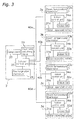
- the indoor control unit 34a comprises a microprocessor, ROM, RAM, various interfaces, and the like. As shown in FIG 3, the indoor control unit 34a is connected to the motor-operated valve 31 a, the indoor fan 32a, and the room temperature thermistor 33a; and inputs the detection signal of the room temperature thermistor 33a. In addition, the indoor control unit 34a transmits a control signal to the motor-operated valve 31a to adjust the opening thereof. Furthermore, if performing room temperature monitoring, discussed later, in the thermo-off state, then the indoor control unit 34a makes the indoor fan 32a driven.
- the outdoor unit 2 comprises a compressor 20, a four-way switching valve 21, an outdoor heat exchanger 22, an accumulator 23, a discharge pipe thermistor 24, an outdoor control unit 25, and the like (refer to FIG 3).
- the compressor 20, the four-way switching valve 21, the outdoor heat exchanger 22, and the accumulator 23 constitute a refrigerant circuit with the indoor units 3a-3d, and the four-way switching valve 21 switches the flow of the refrigerant depending on whether cooling or heating.
- the discharge pipe thermistor 24 is attached on the discharge side of the compressor 20, and detects the discharge pipe temperature on the discharge side of the compressor 20.
- the outdoor control unit 25 comprises a microprocessor, ROM, RAM, various interfaces, and the like. As shown in FIG 3, the outdoor control unit 25 is connected to the discharge pipe thermistor 24, and inputs the detection signal of the discharge pipe thermistor 24. In addition, the outdoor control unit 25 controls air conditioning operation by controlling the operation frequency of the compressor 20 in accordance with various conditions during operation. In addition, the outdoor control unit 25 determines the opening of the motor-operated valve of the indoor unit during operation based on the discharge pipe temperature, and determines the opening of the motor-operated valve of the indoor unit whose operation is halted to be a value proportionate to the opening of the motor-operated valve of the indoor unit during operation.
- a transmission line 40a is provided between the outdoor control unit 25 and the indoor control unit 34a, and various signals can be transmitted and received via this transmission line 40a, such as the control signal of the motor-operated valve 31 a and a signal related to enabling of room temperature monitoring, discussed later.
- indoor units 3b, 3c, 3d are constituted the same as the indoor unit 3a, and are also connected to the outdoor unit 2.
- identical constituent elements are displayed with substituted symbols.
- the motor-operated valve 31a of the indoor unit 3a is indicated as the motor-operated valve 31b of the indoor unit 3b.
- room temperature monitoring is performed wherein the room temperature in each of the indoor units 3a, 3b, 3c, 3d is periodically detected by room temperature thermistors 33a, 33b, 33c, 33d.
- the present air conditioner 1 performs room temperature monitoring in an indoor unit in the thermo-off state, and detects the room temperature of the room wherein that indoor unit is disposed. If any of the indoor control units 34a, 34b, 34c, 34d judge that the respective room temperature has fallen to a fixed value, then it performs control so that it transitions to the thermo-on state.
- the indoor control unit of that indoor unit makes the indoor fan driven, and detects the room temperature. If the indoor fan is thus made to be driven during room temperature monitoring, then room temperature monitoring is performed with respect to the air taken in from inside the room. Consequently, the impact of the heat of the indoor heat exchanger on the room temperature thermistor can be reduced. It is thereby possible to accurately detect the room temperature.
- room temperature monitoring is controlled so that room temperature monitoring by indoor units in the thermo-off state is not started simultaneously in a plurality of indoor units. The following explains the present control.
- the outdoor control unit 25 selects an indoor unit to perform room temperature monitoring, and transmits a room temperature monitoring enable signal to the indoor control unit of the selected indoor unit. At this time, the outdoor control unit 25 transmits the room temperature monitoring enable signal to each of the indoor control units 34a, 34b, 34c, 34d staggered in time.
- Each of the indoor control units 34a, 34b, 34c, 34d judges whether the room temperature monitoring start condition is satisfied. This room temperature monitoring start condition is judged independently in each of the indoor units 3a, 3b, 3c, 3d.
- the indoor control units 34a, 34b, 34c, 34d receive room temperature monitoring enable signals from the outdoor control unit 25, and perform room temperature monitoring if the room temperature monitoring start conditions are satisfied.
- the outdoor control unit 25 judges whether to start room temperature monitoring control on the outdoor unit 2 side.
- the outdoor control unit 25 starts room temperature monitoring control if the following two conditions are both satisfied.
- Tm2(A) indicates a room temperature monitoring enabled timer that measures the time in which room temperature monitoring of the indoor unit 3a is enabled.
- Tm2(B) the monitoring enabled timer of the indoor unit 3b is indicated by Tm2(B). The same notation is used for other timers below.
- Tm01(B) indicates an initially disabled timer of the indoor unit 3b.
- the initially disabled timer measures the time in which room temperature monitoring is initially disabled in each indoor unit from the time when the outdoor control unit 25 starts room temperature monitoring control. Furthermore, as discussed later, the initially disabled timer Tm01(A) of the indoor unit 3a is not depicted in FIG. 4 because it is set to zero.
- the outdoor control unit 25 sets the value of each timer as below..
- a room temperature monitoring disabled time T1 is set to a time when room temperature monitoring of each of the indoor units 3a, 3b, 3c, 3d is disabled, and a room temperature monitoring enabled time T2 is set to a time when room temperature monitoring of each of the indoor units 3a, 3b, 3c, 3d is enabled.
- the room temperature monitoring disabled time T1 and the room temperature monitoring enabled time T2 are equal for each of the indoor units 3a, 3b, 3c, 3d. Accordingly, the timer values of the monitoring enabled timers Tm2(A), Tm2(B), Tm2(C), Tm2(D) of each of the indoor units 3a, 3b, 3c, 3d are all equal to T2.
- the monitoring disabled timers Tm1(A), Tm1(B), Tm1(C), Tm1(D) of each of the indoor units 3a, 3b, 3c, 3d are all equal to T1.
- the monitoring disabled timers measure the time when room temperature monitoring of each of the indoor units 3a, 3b, 3c, 3d is disabled, and measure the monitoring disabled time starting from the second time that room temperature monitoring control is started.
- the value of the initially disabled timer for each of the indoor units 3a, 3b, 3c, 3d is set as below.
- the monitoring interval for each indoor unit means the time from the end of room temperature monitoring enabled of a certain indoor unit until the start of room temperature monitoring enabled of the next indoor unit.
- Tm01(A) ( ⁇ T + T2) ⁇ 0
- Tm01(B) ( ⁇ T + T2) ⁇ 1
- Tm01(C) ( ⁇ T + T2) ⁇ 2
- Tm01(D) ( ⁇ T + T2) ⁇ 3
- the outdoor control unit 25 sets and starts the initially disabled timer of each of the indoor units 3a, 3b, 3c, 3d.
- the outdoor control unit 25 sets and starts the monitoring enabled timer of each of the indoor units 3a, 3b, 3c, 3d. Subsequently, the process of setting and starting the monitoring disabled timers and the monitoring enabled timers is cyclically performed for each of the indoor units 3a, 3b, 3c, 3d while the start condition of the room temperature monitoring is satisfied.
- the monitoring interval ⁇ T 0. This means that, if the count of a monitoring enabled timer of a certain indoor unit is exceeded, then the monitoring enabled timer of another indoor unit is set and started immediately without any time delay.
- the initially disabled timer of each of the indoor units 3a, 3b, 3c, 3d is as follows.
- FIG. 5 shows the relationship among the timers.
- the count of the initially disabled timer Tm01(C) of the indoor unit 3c is exceeded. Further, the monitoring enabled timer Tm2(C) of the indoor unit 3c is simultaneously set and started. The following is the same for the indoor unit 3d.
- the outdoor control unit 25 sends a monitoring enable signal to all of the indoor units 3a, 3b, 3c, 3d, then the outdoor control unit 25 sends a monitoring enable signal to the target indoor units while the above monitoring enabled timers are measuring. Thereby, a monitoring enable signal can be sent to each of the indoor units 3a, 3b, 3c, 3d, staggered in time, under a simple control.
- thermo-off initially disabled timer of that indoor unit is set and started.
- the timer value of the thermo-off initially disabled timer is the room temperature monitoring disabled time T1.
- a monitoring enabled flag f(D) is judged as described below.
- the monitoring enabled flag f(D) 1 if the conditions (3) and (4) below are both satisfied.
- the monitoring enabled flag of each indoor unit is zero when monitoring control starts.
- a monitoring enable signal is sent to the indoor unit 3d if all of the following conditions (7) through (10) are satisfied.
- thermo-off initially disabled timers Tm3(A), Tm3(B), Tm3(C), Tm3(D), of each of the indoor units 3a, 3b, 3c, 3d are reset when room temperature monitoring control starts.
- the number of indoor units that simultaneously perform room temperature monitoring can be limited to just the indoor units in the thermo-off state. Consequently, the number of indoor units subject to limitations is fewer compared with the case wherein a room temperature monitoring enable signal is sent to all of the indoor units 3a, 3b, 3c, 3d. In other words, it is possible to lengthen the time in which the monitoring enable signal is sent per indoor unit. This consequently reduces the probability of an indoor unit losing an opportunity to perform monitoring in the present air conditioner 1.
- room temperature monitoring is performed if the indoor control units 34a, 34b, 34c, 34d receive a room temperature monitoring enable signal and the start condition of room temperature monitoring is satisfied. Consequently, even if a certain indoor control unit judges that the start condition for room temperature monitoring is satisfied based on the conditions inside that indoor unit, then room temperature monitoring is not performed until the outdoor control unit 25 enables room temperature monitoring. Further, the outdoor control unit 25 does not send a monitoring enable signal simultaneously to two or more indoor units, but rather sends a monitoring enable signal to each of the indoor control units 34a, 34b, 34c, 34d, staggered in time. Accordingly, room temperature monitoring is not performed simultaneously for two or more indoor units.
- the indoor fans of two or more indoor units are not made to be driven simultaneously, and the refrigerant is not precipitously affected.
- the indoor fans 32a, 32b, 32c, 32d are made to be driven during room temperature monitoring, and the indoor air is taken into the interior of the indoor units 3a, 3b, 3c, 3d; consequently, the indoor temperature can be accurately detected in the present air conditioner even if the indoor unit is in the thermo-off state.
- the timer values for the monitoring enabled timer and the monitoring disabled timer are the same for each of the indoor units 3a, 3b, 3c, 3d.
- the outdoor control unit 25 sends a monitoring enable signal to the indoor control units 34a, 34b, 34c, 34d with equal timing. Consequently, a room temperature monitoring enable signal is sent to each of the indoor units 3a, 3b, 3c, 3d with the same cycle, staggered in time. Consequently, an opportunity to perform room temperature monitoring is given equally to each of the indoor units 3a, 3b, 3c, 3d. It is thereby possible to suppress biasing the number of times that room temperature monitoring is performed by each of the indoor units 3a, 3b, 3c, 3d.
- the number of indoor units connected to the outdoor unit 2 is not limited to the number recited in the abovementioned embodiment, and may number two, three, five, or more units.
- the monitoring enabled timers for two or more indoor units do not simultaneously measure in the abovementioned embodiment, the monitoring enabled timers may simultaneously measure for two or more indoor units if the impact on the refrigerant is low.
- room temperature monitoring is performed if all of the following are met: the outdoor control unit 25 sends monitoring enable signals, the monitoring start conditions of the indoor units 3a, 3b, 3c, 3d are satisfied, and monitoring enable signals are received.
- the signal sent by the outdoor control unit 25 is not limited to the monitoring enable signal, and a monitoring disable signal may also be sent. In this case, room temperature monitoring is performed if both the monitoring start conditions of the indoor units 3a, 3b, 3c, 3d are satisfied and monitoring disable signals are not received.
- Using the air conditioner according to the present invention enables accurate detection of the indoor temperature, even in an indoor unit in the thermo-off state, while suppressing a precipitous drop in the blow-out temperature in the rooms in operation.
Abstract
Description
- The present invention relates to an air conditioner, and more particularly relates to a multi-room air conditioner wherein a plurality of indoor units is connected to a single outdoor unit.
- A so-called multi-room air conditioner is known wherein, in an air conditioner, a plurality of indoor units is connected to a single outdoor unit. By arranging indoor units in each room of a plurality of rooms, a multi-room air conditioner can air condition a plurality of rooms. In such a multi-room air conditioner, all indoor units are not necessarily operating continuously; some indoor units may be in operation, while the operation of other indoor units may be halted, or in a thermo-off state. In such a case, it is also conceivable that the circulation of refrigerant is unnecessary in indoor units whose operation is halted or is in a thermo-off state. However, to prevent the occurrence of problems due to the pooling of fluid, it is common to flow a minute amount of refrigerant in an indoor unit that is in a thermo-off state or whose heating operation is halted.
- Incidentally, it is also common to provide an air conditioner with a room temperature sensor, and a room temperature monitoring function that detects the indoor temperature. The room interior can thereby be controlled at a comfortable temperature by controlling each of the constituent apparatuses of the air conditioner. Furthermore, to prevent the room temperature sensor of the indoor unit in the thermo-off state from being affected during room temperature monitoring by the heat of an indoor heat exchanger, it is known to detect the room temperature by taking the indoor air into the indoor unit. An indoor fan within the indoor unit in the thermo-off state is therefore driven during room temperature monitoring. The indoor temperature can thereby be detected more accurately. Herein, it is common in the multi-room air conditioner discussed above for each indoor unit to independently judge the start of room temperature monitoring. For example, each indoor unit measures the time with its respective timer, and performs room temperature monitoring at fixed time intervals, e.g., once every five minutes.
- In such a multi-room air conditioner, it is possible for a situation to arise wherein indoor fans are simultaneously driven in a plurality of indoor units in the thermo-off state. In such a case, a problem arises for the following reasons wherein the blow-out temperature in the rooms in operation i.e., the rooms where the indoor units are in operation, falls precipitously. Namely, the refrigerant may condense if the indoor fan is driven because the refrigerant flows in the abovementioned multi-room air conditioner even in the thermo-off state. If this occurs simultaneously in a plurality of indoor units, then the pressure of the refrigerant drops precipitously in the rooms in operation. Consequently, a phenomenon tends to occur in which the blow-out temperature drops precipitously in the rooms in operation. In addition, in a refrigerant circuit wherein a fixed amount of refrigerant is circulating, the entire amount of radiated heat increases if the drive of the indoor fans in a plurality of indoor units is suddenly started. Consequently, the amount of heat radiated by the rooms in operation decreases, and the blow-out temperature falls.
- It is an object of the present invention to provide an air conditioner that can accurately detect the indoor temperature, even in an indoor unit in the thermo-off state, while suppressing a precipitous drop in the blow-out temperature in the rooms in operation.
- The air conditioner as recited in
Claim 1 comprises a plurality of indoor units, an outdoor unit, and a room temperature monitoring control unit. Each indoor unit comprises a room temperature sensor; an indoor heat exchanger; an indoor fan; and an indoor control unit. The outdoor unit comprises an outdoor heat exchanger and constitutes a refrigerant circuit with the plurality of indoor units. The indoor control unit judges whether a start condition of room temperature monitoring is satisfied based on the room temperature sensor, and makes the indoor fan driven if performing room temperature monitoring when heating operation is in the thermo-off state. The room temperature monitoring control unit selects a prescribed indoor unit from the plurality of indoor units, and sends a room temperature monitoring enable-related signal to the indoor control unit of the selected indoor unit. In addition, the indoor control unit determines whether to perform room temperature monitoring based both on the signal and on the start condition of room temperature monitoring. - In the present air conditioner, the indoor control unit determines whether to perform room temperature monitoring based both on the signal received from the room temperature monitoring control unit, and the room temperature monitoring start condition. Consequently, the present air conditioner can limit the number of indoor units that simultaneously perform room temperature monitoring from the room temperature monitoring control unit. Accordingly, the number of simultaneously driven indoor fans can be limited. Thereby, the present air conditioner can accurately detect the indoor temperature, even in an indoor unit in the thermo-off state, while suppressing a precipitous drop in the blow-out temperature in the rooms in operation.
- The invention as recited in
Claim 2 is the air conditioner as recited inClaim 1, wherein the signal is a room temperature monitoring enable signal that enables the performance of room temperature monitoring. Further, the indoor control unit performs room temperature monitoring if the room temperature monitoring enable signal is received and the start condition of room temperature monitoring is satisfied. - In the present air conditioner, room temperature monitoring is performed if the indoor control unit receives a room temperature monitoring enable signal and the room temperature monitoring start condition is satisfied. Consequently, even if a certain indoor control unit judges that the room temperature monitoring start condition is satisfied based on the conditions of the interior of that indoor unit, room temperature monitoring is not performed until the room temperature monitoring control unit enables room temperature monitoring. Accordingly, the number of indoor units that simultaneously perform room temperature monitoring can be limited from the room temperature monitoring control unit. Thereby, the present air conditioner can accurately detect the indoor temperature, even in an indoor unit in the thermo-off state, while suppressing a precipitous drop in the blow-out temperature in the rooms in operation.
- The invention as recited in Claim 3 is the air conditioner as recited in
Claim 2, wherein the room temperature monitoring control unit sends the room temperature monitoring enable signal to each of the indoor control units staggered in time. - In the present air conditioner, room temperature monitoring is not performed simultaneously for two or more indoor units because the room temperature monitoring enable signal is sent to each of the indoor control units staggered in time. Consequently, the present air conditioner can suppress a precipitous drop in the blow-out temperature in the rooms in operation.
- The invention as recited in Claim 4 is the air conditioner as recited in any one claim of
Claim 1 through Claim 3, wherein the room temperature monitoring control unit sends the abovementioned signal to each of the indoor control units with equal timing. - In the present air conditioner, the room temperature monitoring control unit sends the signal to each of the indoor control units with equal timing. Consequently, an opportunity to perform room temperature monitoring is given equally to each of the indoor units. It is thereby possible to suppress biasing the number of times that room temperature monitoring is performed by each of the indoor units.
- The invention as recited in Claim 5 is the air conditioner as recited in any one claim of
Claim 1 through Claim 4, wherein the room temperature monitoring control unit sends the abovementioned signal only to the indoor control units of the indoor units among the plurality of indoor control units wherein heating operation is in the thermo-off state. - In the present air conditioner, the room temperature monitoring control unit sends the signal only to the indoor control units of the indoor units wherein heating operation is in the thermo-off state. Consequently, the probability of an indoor unit losing an opportunity to perform monitoring is small compared with the case wherein a signal is sent to the indoor control units of all of the indoor units.
- The invention as recited in Claim 6 is the air conditioner as recited in any one claim of
Claim 1 through Claim 4, wherein the room temperature monitoring control unit sends the signal to all of the indoor units. - In the present air conditioner, the room temperature monitoring control unit sends a signal to all of the indoor units. Consequently, the room temperature monitoring control unit does not need to judge whether the indoor unit is in the thermo-off state. The details of control are consequently simplified, lightening the burden placed on the room temperature monitoring control unit.
-
- FIG. 1 is an external view of the air conditioner.
- FIG. 2 is a schematic of the refrigerant circuit of the air conditioner.
- FIG 3 is a control block diagram of the air conditioner.
- FIG 4 depicts the relationship among each of the timers.
- FIG 5 depicts a concrete example of each of the timers.
- FIG 6 depicts the timers for the case wherein one of the indoor units is in the thermo-off state.
- FIG 1 depicts an
air conditioner 1 that is used in one embodiment of the present invention. - The
air conditioner 1 is a so-called multi-room air conditioner, wherein a plurality of indoor units is connected to a single outdoor unit. - In the
present air conditioner 1, fourindoor units refrigerant pipes outdoor unit 2. These fourindoor units - FIG 2 depicts a schematic of the refrigerant circuit of the
present air conditioner 1. - The refrigerant circuit comprises a single
outdoor unit 2, and fourindoor units outdoor unit 2. - The
indoor unit 3a comprises anindoor heat exchanger 30a, a motor-operatedvalve 31a, anindoor fan 32a, aroom temperature thermistor 33a, and anindoor control unit 34a (refer to FIG. 3). - The
indoor heat exchanger 30a and the motor-operatedvalve 31a are connected in series, and constitute a refrigerant circuit with theoutdoor unit 2. The motor-operatedvalve 31a is provided on the outlet side of theindoor heat exchanger 30a, and controls the amount of the refrigerant flowing to theindoor heat exchanger 30a. - The
indoor fan 32a is provided inside theindoor unit 3a and is made to be driven by theindoor control unit 34a. Theindoor fan 32a takes into the interior of theindoor unit 3a the indoor air in which theindoor unit 3a is disposed, and sends indoors the air that has been heat exchanged by theindoor heat exchanger 30a. - The
room temperature thermistor 33a is provided inside theindoor unit 3a, detects the indoor temperature, and sends a detection signal to theindoor control unit 34a. - The
indoor control unit 34a comprises a microprocessor, ROM, RAM, various interfaces, and the like. As shown in FIG 3, theindoor control unit 34a is connected to the motor-operatedvalve 31 a, theindoor fan 32a, and theroom temperature thermistor 33a; and inputs the detection signal of theroom temperature thermistor 33a. In addition, theindoor control unit 34a transmits a control signal to the motor-operatedvalve 31a to adjust the opening thereof. Furthermore, if performing room temperature monitoring, discussed later, in the thermo-off state, then theindoor control unit 34a makes theindoor fan 32a driven. - The
outdoor unit 2 comprises acompressor 20, a four-way switching valve 21, anoutdoor heat exchanger 22, anaccumulator 23, adischarge pipe thermistor 24, anoutdoor control unit 25, and the like (refer to FIG 3). - The
compressor 20, the four-way switching valve 21, theoutdoor heat exchanger 22, and theaccumulator 23 constitute a refrigerant circuit with theindoor units 3a-3d, and the four-way switching valve 21 switches the flow of the refrigerant depending on whether cooling or heating. - The
discharge pipe thermistor 24 is attached on the discharge side of thecompressor 20, and detects the discharge pipe temperature on the discharge side of thecompressor 20. - The
outdoor control unit 25 comprises a microprocessor, ROM, RAM, various interfaces, and the like. As shown in FIG 3, theoutdoor control unit 25 is connected to thedischarge pipe thermistor 24, and inputs the detection signal of thedischarge pipe thermistor 24. In addition, theoutdoor control unit 25 controls air conditioning operation by controlling the operation frequency of thecompressor 20 in accordance with various conditions during operation. In addition, theoutdoor control unit 25 determines the opening of the motor-operated valve of the indoor unit during operation based on the discharge pipe temperature, and determines the opening of the motor-operated valve of the indoor unit whose operation is halted to be a value proportionate to the opening of the motor-operated valve of the indoor unit during operation. - A
transmission line 40a is provided between theoutdoor control unit 25 and theindoor control unit 34a, and various signals can be transmitted and received via thistransmission line 40a, such as the control signal of the motor-operatedvalve 31 a and a signal related to enabling of room temperature monitoring, discussed later. - Other
indoor units indoor unit 3a, and are also connected to theoutdoor unit 2. In FIG 2 and FIG 3, identical constituent elements are displayed with substituted symbols. For example, the motor-operatedvalve 31a of theindoor unit 3a is indicated as the motor-operatedvalve 31b of theindoor unit 3b. - In the
present air conditioner 1, room temperature monitoring is performed wherein the room temperature in each of theindoor units room temperature thermistors present air conditioner 1 performs room temperature monitoring in an indoor unit in the thermo-off state, and detects the room temperature of the room wherein that indoor unit is disposed. If any of theindoor control units - In the
present air conditioner 1, if room temperature monitoring is performed in an indoor unit in the thermo-off state during heating operation, then the indoor control unit of that indoor unit makes the indoor fan driven, and detects the room temperature. If the indoor fan is thus made to be driven during room temperature monitoring, then room temperature monitoring is performed with respect to the air taken in from inside the room. Consequently, the impact of the heat of the indoor heat exchanger on the room temperature thermistor can be reduced. It is thereby possible to accurately detect the room temperature. - However, if the drive of indoor fans by indoor units in the thermo-off state is started simultaneously in a plurality of indoor units, then the pressure of the refrigerant can precipitously fall due to condensation, causing a phenomenon wherein the blow-out temperature of the indoor units in the rooms in operation drops precipitously.
- To suppress such a phenomenon in the
present air conditioner 1, room temperature monitoring is controlled so that room temperature monitoring by indoor units in the thermo-off state is not started simultaneously in a plurality of indoor units. The following explains the present control. - First, room temperature monitoring control will be briefly explained.
- The
outdoor control unit 25 selects an indoor unit to perform room temperature monitoring, and transmits a room temperature monitoring enable signal to the indoor control unit of the selected indoor unit. At this time, theoutdoor control unit 25 transmits the room temperature monitoring enable signal to each of theindoor control units - Each of the
indoor control units indoor units indoor control units outdoor control unit 25, and perform room temperature monitoring if the room temperature monitoring start conditions are satisfied. - The following discusses the details of the room temperature monitoring control on the
outdoor control unit 25 side. - First, the
outdoor control unit 25 judges whether to start room temperature monitoring control on theoutdoor unit 2 side. - The
outdoor control unit 25 starts room temperature monitoring control if the following two conditions are both satisfied. - (1) The
air conditioner 1 is in heating operation. - (2) The
air conditioner 1 is not defrosting. - Next, as shown in FIG 4, various room temperature monitoring timers are set and started for each of the
indoor units indoor unit 3a is enabled. In addition, this is shown for the otherindoor units indoor unit 3b is indicated by Tm2(B). The same notation is used for other timers below. - Tm01(B) indicates an initially disabled timer of the
indoor unit 3b. The initially disabled timer measures the time in which room temperature monitoring is initially disabled in each indoor unit from the time when theoutdoor control unit 25 starts room temperature monitoring control. Furthermore, as discussed later, the initially disabled timer Tm01(A) of theindoor unit 3a is not depicted in FIG. 4 because it is set to zero. - The
outdoor control unit 25 sets the value of each timer as below.. - First, a room temperature monitoring disabled time T1 is set to a time when room temperature monitoring of each of the
indoor units indoor units indoor units indoor units indoor units indoor units - The value of the initially disabled timer for each of the
indoor units - First, if we let N be the number of indoor units that performs room temperature monitoring, then the monitoring interval ΔT for each of the
indoor units 
- Furthermore, the monitoring interval for each indoor unit means the time from the end of room temperature monitoring enabled of a certain indoor unit until the start of room temperature monitoring enabled of the next indoor unit.
- If room temperature monitoring is performed in the order of the
indoor unit 3a, theindoor unit 3b, theindoor unit 3c, and theindoor unit 3d, then the timer value of the initially disabled timer for each indoor unit is assigned by the following formulas.


- When room temperature monitoring control starts, the
outdoor control unit 25 sets and starts the initially disabled timer of each of theindoor units - Subsequently, if the initially disabled timer of each of the
indoor units outdoor control unit 25 sets and starts the monitoring enabled timer of each of theindoor units indoor units - The following describes a concrete example of the count for each of the timers.
- Let room temperature monitoring disabled time T1 = 270 s, room temperature monitoring enabled time T2 = 90 s, and N = 4.
- Under these conditions, the monitoring interval ΔT = 0. This means that, if the count of a monitoring enabled timer of a certain indoor unit is exceeded, then the monitoring enabled timer of another indoor unit is set and started immediately without any time delay.
- The initially disabled timer of each of the
indoor units - Tm01(A) = 0 s
- Tm01(B) = 90 s
- Tm01(C) = 180 s
- Tm01(D) = 270 s
- For each of the
indoor units - FIG. 5 shows the relationship among the timers.
- When room temperature monitoring control starts, the
outdoor control unit 25 sets and starts the initially disabled timers Tm01(A) = 0 s, Tm01(B) = 90 s, Tm01(C) = 180 s, Tm01(D) = 270 s of theindoor units - The monitoring enabled timer Tm2(A) = 90 s is set and started immediately for the
indoor unit 3a because the initially disabled timer Tm01(A) = 0 s for theindoor unit 3a. - The monitoring enabled timer Tm2(A) of the
indoor unit 3a and the initially disabled timer Tm01(B) of theindoor unit 3b both exceed their count simultaneously because the initially disabled timer of theindoor unit 3b is Tm01(B) = 90 s. Further, the monitoring enabled timer Tm2(B) of theindoor unit 3b is then set and started. In addition, simultaneous with the count of Tm2(A) being exceeded, the monitoring disabled timer Tm1(A) = 270 s (not shown) is set and started for theindoor unit 3a. - Simultaneous with the monitoring enabled timer Tm2(B) of the
indoor unit 3b exceeding its count, the count of the initially disabled timer Tm01(C) of theindoor unit 3c is exceeded. Further, the monitoring enabled timer Tm2(C) of theindoor unit 3c is simultaneously set and started. The following is the same for theindoor unit 3d. - When the count of the monitoring enabled timer Tm2(D) of the
indoor unit 3d is exceeded, the count of the monitoring disabled timer Tm1(A) (not shown) of theindoor unit 3a is exceeded, and the monitoring enabled timer Tm2(A) of theindoor unit 3a is once again set and started. Subsequently, the present control is repeated. - Regardless of whether the
indoor units outdoor control unit 25 sends a monitoring enable signal to all of theindoor units outdoor control unit 25 sends a monitoring enable signal to the target indoor units while the above monitoring enabled timers are measuring. Thereby, a monitoring enable signal can be sent to each of theindoor units - If a monitoring enable signal is sent only to indoor units in the thermo-off state in heating operation, then the following type of control is performed in addition to the abovementioned control.
- If the certain indoor unit previously in the thermo-on state transitions to the thermo-off state, then a thermo-off initially disabled timer of that indoor unit is set and started. The timer value of the thermo-off initially disabled timer is the room temperature monitoring disabled time T1. The following explains, as shown in FIG. 6, that the
indoor unit 3d is taken to be in the thermo-off state during the count of the monitoring enabled timer Tm2(A) of theindoor unit 3a. - In the present control process, a monitoring enabled flag f(D) is judged as described below. The monitoring enabled flag f(D) = 1 if the conditions (3) and (4) below are both satisfied.
- (3) The count of the thermo-off initially disabled timer Tm3(D) is exceeded.
- (4) The monitoring enabled timer Tm2(D) is not measuring.
In addition, the monitoring enabled flag f(D) = 0 if the conditions (5) and (6) below are both satisfied. - (5) The thermo-off initially disabled timer Tm3(D) is measuring.
- (6) The monitoring enabled timer Tm2(D) is not measuring.
- Furthermore, the monitoring enabled flag of each indoor unit is zero when monitoring control starts.
- Next, a monitoring enable signal is sent to the
indoor unit 3d if all of the following conditions (7) through (10) are satisfied. - (7) The thermo-off initially disabled timer Tm3(D) of the
indoor unit 3d is not measuring. - (8) The
indoor unit 3d is in the heating thermo-off state. - (9) The monitoring enabled timer Tm2(D) of the
indoor unit 3d is measuring. - (10) The monitoring enabled flag f(D) = 1 for the
indoor unit 3d. - Furthermore, the thermo-off initially disabled timers Tm3(A), Tm3(B), Tm3(C), Tm3(D), of each of the
indoor units - Based on the above control, the number of indoor units that simultaneously perform room temperature monitoring can be limited to just the indoor units in the thermo-off state. Consequently, the number of indoor units subject to limitations is fewer compared with the case wherein a room temperature monitoring enable signal is sent to all of the
indoor units present air conditioner 1. - In the
present air conditioner 1, room temperature monitoring is performed if theindoor control units outdoor control unit 25 enables room temperature monitoring. Further, theoutdoor control unit 25 does not send a monitoring enable signal simultaneously to two or more indoor units, but rather sends a monitoring enable signal to each of theindoor control units present air conditioner 1, a precipitous drop in the blow-out temperature in the rooms in operation can be suppressed. Further, theindoor fans indoor units - Furthermore, the timer values for the monitoring enabled timer and the monitoring disabled timer are the same for each of the
indoor units outdoor control unit 25 sends a monitoring enable signal to theindoor control units indoor units indoor units indoor units - The number of indoor units connected to the
outdoor unit 2 is not limited to the number recited in the abovementioned embodiment, and may number two, three, five, or more units. - In addition, although the monitoring enabled timers for two or more indoor units do not simultaneously measure in the abovementioned embodiment, the monitoring enabled timers may simultaneously measure for two or more indoor units if the impact on the refrigerant is low.
- In the abovementioned embodiment, room temperature monitoring is performed if all of the following are met: the
outdoor control unit 25 sends monitoring enable signals, the monitoring start conditions of theindoor units outdoor control unit 25 is not limited to the monitoring enable signal, and a monitoring disable signal may also be sent. In this case, room temperature monitoring is performed if both the monitoring start conditions of theindoor units - Using the air conditioner according to the present invention enables accurate detection of the indoor temperature, even in an indoor unit in the thermo-off state, while suppressing a precipitous drop in the blow-out temperature in the rooms in operation.
Claims (6)
- An air conditioner, comprising:a plurality of indoor units (3a, 3b, 3c, 3d), each comprising a room temperature sensor (33a, 33b, 33c, 33d); an indoor heat exchanger (30a, 30b, 30c, 30d); an indoor fan (32a, 32b, 32c, 32d); and an indoor control unit (34a, 34b, 34c, 34d) that judges whether a start condition of room temperature monitoring is satisfied based on said room temperature sensor (33a, 33b, 33c, 33d), and that makes said indoor fan (32a, 32b, 32c, 32d) driven if performing room temperature monitoring when heating operation is in the thermo-off state;an outdoor unit (2) comprising an outdoor heat exchanger (22) and constituting a refrigerant circuit with said plurality of indoor units (3a, 3b, 3c, 3d); anda room temperature monitoring control unit .(25) that selects a prescribed indoor unit from said plurality of indoor units (3a, 3b, 3c, 3d), and sends a room temperature monitoring enable-related signal to the indoor control unit of the selected said indoor unit,wherein,
said indoor control unit (34a, 34b, 34c, 34d) determines whether to perform room temperature monitoring based both on said signal and on the start condition of said room temperature monitoring. - The air conditioner as recited in Claim 1, wherein
said signal is a room temperature monitoring enable signal that enables the performance of room temperature monitoring; and
said indoor control unit (34a, 34b, 34c, 34d) performs room temperature monitoring if said room temperature monitoring enable signal is received and the start condition of said room temperature monitoring is satisfied. - The air conditioner as recited in Claim 2, wherein
said room temperature monitoring control unit (25) sends said room temperature monitoring enable signal to each of said indoor control units (34a, 34b, 34c, 34d) staggered in time. - The air conditioner as recited in any one claim of Claim 1 through Claim 3, wherein
said room temperature monitoring control unit (25) sends said signal to each of said indoor control units (34a, 34b, 34c, 34d) with equal timing. - The air conditioner as recited in any one claim of Claim 1 through Claim 4,
wherein said room temperature monitoring control unit sends said signal only to the indoor control units of the indoor units among said plurality of indoor control units (34a, 34b, 34c, 34d) wherein heating operation is in the thermo-off state. - The air conditioner as recited in any one claim of Claim 1 through Claim 4,
wherein said room temperature monitoring control unit sends said signal to all of said indoor units (34a, 34b, 34c, 34d).
Applications Claiming Priority (3)
| Application Number | Priority Date | Filing Date | Title |
|---|---|---|---|
| JP2002092313 | 2002-03-28 | ||
| JP2002092313A JP3778117B2 (en) | 2002-03-28 | 2002-03-28 | Air conditioner |
| PCT/JP2003/002609 WO2003083377A1 (en) | 2002-03-28 | 2003-03-05 | Air conditioner |
Publications (3)
| Publication Number | Publication Date |
|---|---|
| EP1491826A1 true EP1491826A1 (en) | 2004-12-29 |
| EP1491826A4 EP1491826A4 (en) | 2010-05-05 |
| EP1491826B1 EP1491826B1 (en) | 2016-08-03 |
Family
ID=28671703
Family Applications (1)
| Application Number | Title | Priority Date | Filing Date |
|---|---|---|---|
| EP03745406.3A Expired - Lifetime EP1491826B1 (en) | 2002-03-28 | 2003-03-05 | Air conditioner |
Country Status (6)
| Country | Link |
|---|---|
| EP (1) | EP1491826B1 (en) |
| JP (1) | JP3778117B2 (en) |
| CN (1) | CN1284951C (en) |
| AU (1) | AU2003211720B2 (en) |
| ES (1) | ES2598355T3 (en) |
| WO (1) | WO2003083377A1 (en) |
Cited By (3)
| Publication number | Priority date | Publication date | Assignee | Title |
|---|---|---|---|---|
| EP2071251A1 (en) * | 2006-09-19 | 2009-06-17 | Daikin Industries, Ltd. | Air-conditioning control intermediate device, air-conditioning control system, air-conditioning control method, and air-conditioning control program |
| EP2835595A4 (en) * | 2012-04-06 | 2015-12-30 | Mitsubishi Heavy Ind Ltd | Control device, method, and program, and multi-type air conditioning system comprising same |
| EP2665977A4 (en) * | 2011-01-21 | 2018-01-10 | LG Electronics Inc. | Central control system and method for setting control point thereof |
Families Citing this family (5)
| Publication number | Priority date | Publication date | Assignee | Title |
|---|---|---|---|---|
| JP5916488B2 (en) | 2012-04-06 | 2016-05-11 | 三菱重工業株式会社 | Control apparatus and method, program, and multi-type air conditioning system including the same |
| CN102829531A (en) * | 2012-09-25 | 2012-12-19 | 广东志高暖通设备股份有限公司 | Method for detecting ambient temperature of indoor unit of VRV |
| JP6494797B2 (en) * | 2015-12-17 | 2019-04-03 | 三菱電機株式会社 | Air conditioning system |
| CN112714847A (en) | 2018-09-20 | 2021-04-27 | 东芝开利株式会社 | Air conditioner and control method |
| JP2024013014A (en) * | 2022-07-19 | 2024-01-31 | 三菱重工サーマルシステムズ株式会社 | Air conditioner and control method |
Citations (3)
| Publication number | Priority date | Publication date | Assignee | Title |
|---|---|---|---|---|
| JPH01114655A (en) * | 1987-10-28 | 1989-05-08 | Matsushita Seiko Co Ltd | Electric power demand controller |
| JPH03144246A (en) * | 1989-10-30 | 1991-06-19 | Daikin Ind Ltd | Operation control device for air conditioner |
| JPH07174396A (en) * | 1993-05-25 | 1995-07-14 | Mitsubishi Electric Corp | Multi-type air conditioner |
Family Cites Families (2)
| Publication number | Priority date | Publication date | Assignee | Title |
|---|---|---|---|---|
| JPH11173628A (en) * | 1997-12-15 | 1999-07-02 | Mitsubishi Heavy Ind Ltd | Air conditioner |
| JP2002013784A (en) * | 2000-06-29 | 2002-01-18 | Sanyo Electric Co Ltd | Air-conditioning system |
-
2002
- 2002-03-28 JP JP2002092313A patent/JP3778117B2/en not_active Expired - Fee Related
-
2003
- 2003-03-05 CN CNB038069555A patent/CN1284951C/en not_active Expired - Lifetime
- 2003-03-05 AU AU2003211720A patent/AU2003211720B2/en not_active Ceased
- 2003-03-05 WO PCT/JP2003/002609 patent/WO2003083377A1/en active IP Right Grant
- 2003-03-05 EP EP03745406.3A patent/EP1491826B1/en not_active Expired - Lifetime
- 2003-03-05 ES ES03745406.3T patent/ES2598355T3/en not_active Expired - Lifetime
Patent Citations (3)
| Publication number | Priority date | Publication date | Assignee | Title |
|---|---|---|---|---|
| JPH01114655A (en) * | 1987-10-28 | 1989-05-08 | Matsushita Seiko Co Ltd | Electric power demand controller |
| JPH03144246A (en) * | 1989-10-30 | 1991-06-19 | Daikin Ind Ltd | Operation control device for air conditioner |
| JPH07174396A (en) * | 1993-05-25 | 1995-07-14 | Mitsubishi Electric Corp | Multi-type air conditioner |
Non-Patent Citations (1)
| Title |
|---|
| See also references of WO03083377A1 * |
Cited By (4)
| Publication number | Priority date | Publication date | Assignee | Title |
|---|---|---|---|---|
| EP2071251A1 (en) * | 2006-09-19 | 2009-06-17 | Daikin Industries, Ltd. | Air-conditioning control intermediate device, air-conditioning control system, air-conditioning control method, and air-conditioning control program |
| EP2071251A4 (en) * | 2006-09-19 | 2012-01-04 | Daikin Ind Ltd | Air-conditioning control intermediate device, air-conditioning control system, air-conditioning control method, and air-conditioning control program |
| EP2665977A4 (en) * | 2011-01-21 | 2018-01-10 | LG Electronics Inc. | Central control system and method for setting control point thereof |
| EP2835595A4 (en) * | 2012-04-06 | 2015-12-30 | Mitsubishi Heavy Ind Ltd | Control device, method, and program, and multi-type air conditioning system comprising same |
Also Published As
| Publication number | Publication date |
|---|---|
| JP2003287258A (en) | 2003-10-10 |
| JP3778117B2 (en) | 2006-05-24 |
| CN1643305A (en) | 2005-07-20 |
| WO2003083377A1 (en) | 2003-10-09 |
| AU2003211720B2 (en) | 2006-02-23 |
| EP1491826A4 (en) | 2010-05-05 |
| CN1284951C (en) | 2006-11-15 |
| AU2003211720A1 (en) | 2003-10-13 |
| EP1491826B1 (en) | 2016-08-03 |
| ES2598355T3 (en) | 2017-01-27 |
Similar Documents
| Publication | Publication Date | Title |
|---|---|---|
| JP6297217B2 (en) | Fluid supply device for temperature adjustment | |
| EP2981772B1 (en) | Heat-pump system with refrigerant charge diagnostics | |
| US8104299B2 (en) | Air conditioner | |
| US10024589B2 (en) | Air conditioner having defrosting operation | |
| US4850200A (en) | Refrigerating circuit device for air conditioning apparatus and control method thereof | |
| KR100715999B1 (en) | Multi Airconditioner and its operating Method | |
| EP2204622A1 (en) | Compressor operation control device and air conditioner using the same | |
| CA2530895C (en) | Air-conditioning system with multiple indoor and outdoor units and control system therefore | |
| JP5622859B2 (en) | Heat source equipment | |
| EP1491826B1 (en) | Air conditioner | |
| JP2013200085A (en) | Air conditioner | |
| JP6719651B2 (en) | Refrigeration cycle system and communication traffic adjustment method | |
| KR19990072624A (en) | Air conditioner having a number of indoor heat exchanger | |
| JP3377632B2 (en) | Air conditioner | |
| CN111750490B (en) | Air conditioner and control method | |
| EP3553404B1 (en) | Air conditioning system | |
| KR101995584B1 (en) | Air-conditioning system and controlling method thereof | |
| JP2550649B2 (en) | Refrigeration equipment | |
| KR100187286B1 (en) | Data transmit-receiving device of multi- airconditioner and its method | |
| JP2011214781A (en) | Multi-room type air conditioner | |
| US20230013674A1 (en) | Variable capacity defrost | |
| JPH0486445A (en) | Air conditioner | |
| WO2018207304A1 (en) | Air conditioner | |
| JP2024064351A (en) | Air conditioners | |
| JPH0733921B2 (en) | Air conditioner |
Legal Events
| Date | Code | Title | Description |
|---|---|---|---|
| PUAI | Public reference made under article 153(3) epc to a published international application that has entered the european phase |
Free format text: ORIGINAL CODE: 0009012 |
|
| 17P | Request for examination filed |
Effective date: 20041008 |
|
| AK | Designated contracting states |
Kind code of ref document: A1 Designated state(s): AT BE BG CH CY CZ DE DK EE ES FI FR GB GR HU IE IT LI LU MC NL PT RO SE SI SK TR |
|
| A4 | Supplementary search report drawn up and despatched |
Effective date: 20100401 |
|
| RIC1 | Information provided on ipc code assigned before grant |
Ipc: F25B 13/00 20060101ALI20100326BHEP Ipc: F24F 11/02 20060101AFI20031016BHEP |
|
| 17Q | First examination report despatched |
Effective date: 20100727 |
|
| GRAP | Despatch of communication of intention to grant a patent |
Free format text: ORIGINAL CODE: EPIDOSNIGR1 |
|
| RIC1 | Information provided on ipc code assigned before grant |
Ipc: F25B 13/00 20060101ALI20160114BHEP Ipc: F24F 11/02 20060101AFI20160114BHEP |
|
| INTG | Intention to grant announced |
Effective date: 20160218 |
|
| GRAS | Grant fee paid |
Free format text: ORIGINAL CODE: EPIDOSNIGR3 |
|
| GRAA | (expected) grant |
Free format text: ORIGINAL CODE: 0009210 |
|
| AK | Designated contracting states |
Kind code of ref document: B1 Designated state(s): AT BE BG CH CY CZ DE DK EE ES FI FR GB GR HU IE IT LI LU MC NL PT RO SE SI SK TR |
|
| REG | Reference to a national code |
Ref country code: GB Ref legal event code: FG4D |
|
| RIN1 | Information on inventor provided before grant (corrected) |
Inventor name: NAGAMINE, MITSUAKI Inventor name: KATAOKA, HIDEHIKO |
|
| REG | Reference to a national code |
Ref country code: CH Ref legal event code: EP Ref country code: AT Ref legal event code: REF Ref document number: 817594 Country of ref document: AT Kind code of ref document: T Effective date: 20160815 |
|
| REG | Reference to a national code |
Ref country code: IE Ref legal event code: FG4D |
|
| REG | Reference to a national code |
Ref country code: DE Ref legal event code: R096 Ref document number: 60349211 Country of ref document: DE |
|
| REG | Reference to a national code |
Ref country code: NL Ref legal event code: MP Effective date: 20160803 |
|
| REG | Reference to a national code |
Ref country code: AT Ref legal event code: MK05 Ref document number: 817594 Country of ref document: AT Kind code of ref document: T Effective date: 20160803 |
|
| REG | Reference to a national code |
Ref country code: ES Ref legal event code: FG2A Ref document number: 2598355 Country of ref document: ES Kind code of ref document: T3 Effective date: 20170127 |
|
| PG25 | Lapsed in a contracting state [announced via postgrant information from national office to epo] |
Ref country code: NL Free format text: LAPSE BECAUSE OF FAILURE TO SUBMIT A TRANSLATION OF THE DESCRIPTION OR TO PAY THE FEE WITHIN THE PRESCRIBED TIME-LIMIT Effective date: 20160803 Ref country code: FI Free format text: LAPSE BECAUSE OF FAILURE TO SUBMIT A TRANSLATION OF THE DESCRIPTION OR TO PAY THE FEE WITHIN THE PRESCRIBED TIME-LIMIT Effective date: 20160803 |
|
| PG25 | Lapsed in a contracting state [announced via postgrant information from national office to epo] |
Ref country code: SE Free format text: LAPSE BECAUSE OF FAILURE TO SUBMIT A TRANSLATION OF THE DESCRIPTION OR TO PAY THE FEE WITHIN THE PRESCRIBED TIME-LIMIT Effective date: 20160803 Ref country code: GR Free format text: LAPSE BECAUSE OF FAILURE TO SUBMIT A TRANSLATION OF THE DESCRIPTION OR TO PAY THE FEE WITHIN THE PRESCRIBED TIME-LIMIT Effective date: 20161104 Ref country code: AT Free format text: LAPSE BECAUSE OF FAILURE TO SUBMIT A TRANSLATION OF THE DESCRIPTION OR TO PAY THE FEE WITHIN THE PRESCRIBED TIME-LIMIT Effective date: 20160803 Ref country code: PT Free format text: LAPSE BECAUSE OF FAILURE TO SUBMIT A TRANSLATION OF THE DESCRIPTION OR TO PAY THE FEE WITHIN THE PRESCRIBED TIME-LIMIT Effective date: 20161205 |
|
| REG | Reference to a national code |
Ref country code: FR Ref legal event code: PLFP Year of fee payment: 15 |
|
| PG25 | Lapsed in a contracting state [announced via postgrant information from national office to epo] |
Ref country code: RO Free format text: LAPSE BECAUSE OF FAILURE TO SUBMIT A TRANSLATION OF THE DESCRIPTION OR TO PAY THE FEE WITHIN THE PRESCRIBED TIME-LIMIT Effective date: 20160803 Ref country code: EE Free format text: LAPSE BECAUSE OF FAILURE TO SUBMIT A TRANSLATION OF THE DESCRIPTION OR TO PAY THE FEE WITHIN THE PRESCRIBED TIME-LIMIT Effective date: 20160803 |
|
| REG | Reference to a national code |
Ref country code: DE Ref legal event code: R097 Ref document number: 60349211 Country of ref document: DE |
|
| PG25 | Lapsed in a contracting state [announced via postgrant information from national office to epo] |
Ref country code: CZ Free format text: LAPSE BECAUSE OF FAILURE TO SUBMIT A TRANSLATION OF THE DESCRIPTION OR TO PAY THE FEE WITHIN THE PRESCRIBED TIME-LIMIT Effective date: 20160803 Ref country code: BG Free format text: LAPSE BECAUSE OF FAILURE TO SUBMIT A TRANSLATION OF THE DESCRIPTION OR TO PAY THE FEE WITHIN THE PRESCRIBED TIME-LIMIT Effective date: 20161103 Ref country code: SK Free format text: LAPSE BECAUSE OF FAILURE TO SUBMIT A TRANSLATION OF THE DESCRIPTION OR TO PAY THE FEE WITHIN THE PRESCRIBED TIME-LIMIT Effective date: 20160803 Ref country code: DK Free format text: LAPSE BECAUSE OF FAILURE TO SUBMIT A TRANSLATION OF THE DESCRIPTION OR TO PAY THE FEE WITHIN THE PRESCRIBED TIME-LIMIT Effective date: 20160803 Ref country code: BE Free format text: LAPSE BECAUSE OF FAILURE TO SUBMIT A TRANSLATION OF THE DESCRIPTION OR TO PAY THE FEE WITHIN THE PRESCRIBED TIME-LIMIT Effective date: 20160803 |
|
| PLBE | No opposition filed within time limit |
Free format text: ORIGINAL CODE: 0009261 |
|
| STAA | Information on the status of an ep patent application or granted ep patent |
Free format text: STATUS: NO OPPOSITION FILED WITHIN TIME LIMIT |
|
| 26N | No opposition filed |
Effective date: 20170504 |
|
| PG25 | Lapsed in a contracting state [announced via postgrant information from national office to epo] |
Ref country code: SI Free format text: LAPSE BECAUSE OF FAILURE TO SUBMIT A TRANSLATION OF THE DESCRIPTION OR TO PAY THE FEE WITHIN THE PRESCRIBED TIME-LIMIT Effective date: 20160803 |
|
| REG | Reference to a national code |
Ref country code: CH Ref legal event code: PL |
|
| REG | Reference to a national code |
Ref country code: DE Ref legal event code: R079 Ref document number: 60349211 Country of ref document: DE Free format text: PREVIOUS MAIN CLASS: F24F0011020000 Ipc: F24F0011890000 |
|
| PG25 | Lapsed in a contracting state [announced via postgrant information from national office to epo] |
Ref country code: MC Free format text: LAPSE BECAUSE OF FAILURE TO SUBMIT A TRANSLATION OF THE DESCRIPTION OR TO PAY THE FEE WITHIN THE PRESCRIBED TIME-LIMIT Effective date: 20160803 |
|
| REG | Reference to a national code |
Ref country code: IE Ref legal event code: MM4A |
|
| PG25 | Lapsed in a contracting state [announced via postgrant information from national office to epo] |
Ref country code: LU Free format text: LAPSE BECAUSE OF NON-PAYMENT OF DUE FEES Effective date: 20170305 |
|
| REG | Reference to a national code |
Ref country code: FR Ref legal event code: PLFP Year of fee payment: 16 |
|
| PG25 | Lapsed in a contracting state [announced via postgrant information from national office to epo] |
Ref country code: IE Free format text: LAPSE BECAUSE OF NON-PAYMENT OF DUE FEES Effective date: 20170305 Ref country code: LI Free format text: LAPSE BECAUSE OF NON-PAYMENT OF DUE FEES Effective date: 20170331 Ref country code: CH Free format text: LAPSE BECAUSE OF NON-PAYMENT OF DUE FEES Effective date: 20170331 |
|
| PG25 | Lapsed in a contracting state [announced via postgrant information from national office to epo] |
Ref country code: HU Free format text: LAPSE BECAUSE OF FAILURE TO SUBMIT A TRANSLATION OF THE DESCRIPTION OR TO PAY THE FEE WITHIN THE PRESCRIBED TIME-LIMIT; INVALID AB INITIO Effective date: 20030305 |
|
| PG25 | Lapsed in a contracting state [announced via postgrant information from national office to epo] |
Ref country code: CY Free format text: LAPSE BECAUSE OF NON-PAYMENT OF DUE FEES Effective date: 20160803 |
|
| PG25 | Lapsed in a contracting state [announced via postgrant information from national office to epo] |
Ref country code: TR Free format text: LAPSE BECAUSE OF FAILURE TO SUBMIT A TRANSLATION OF THE DESCRIPTION OR TO PAY THE FEE WITHIN THE PRESCRIBED TIME-LIMIT Effective date: 20160803 |
|
| PGFP | Annual fee paid to national office [announced via postgrant information from national office to epo] |
Ref country code: ES Payment date: 20210407 Year of fee payment: 19 |
|
| PGFP | Annual fee paid to national office [announced via postgrant information from national office to epo] |
Ref country code: GB Payment date: 20220127 Year of fee payment: 20 Ref country code: DE Payment date: 20220203 Year of fee payment: 20 |
|
| PGFP | Annual fee paid to national office [announced via postgrant information from national office to epo] |
Ref country code: IT Payment date: 20220210 Year of fee payment: 20 Ref country code: FR Payment date: 20220210 Year of fee payment: 20 |
|
| REG | Reference to a national code |
Ref country code: DE Ref legal event code: R071 Ref document number: 60349211 Country of ref document: DE |
|
| REG | Reference to a national code |
Ref country code: GB Ref legal event code: PE20 Expiry date: 20230304 |
|
| REG | Reference to a national code |
Ref country code: ES Ref legal event code: FD2A Effective date: 20230427 |
|
| PG25 | Lapsed in a contracting state [announced via postgrant information from national office to epo] |
Ref country code: GB Free format text: LAPSE BECAUSE OF EXPIRATION OF PROTECTION Effective date: 20230304 |
|
| PG25 | Lapsed in a contracting state [announced via postgrant information from national office to epo] |
Ref country code: ES Free format text: LAPSE BECAUSE OF NON-PAYMENT OF DUE FEES Effective date: 20220306 |