EP1491401A2 - Method and structure for positioning headlamp on vehicle body - Google Patents
Method and structure for positioning headlamp on vehicle body Download PDFInfo
- Publication number
- EP1491401A2 EP1491401A2 EP20040013682 EP04013682A EP1491401A2 EP 1491401 A2 EP1491401 A2 EP 1491401A2 EP 20040013682 EP20040013682 EP 20040013682 EP 04013682 A EP04013682 A EP 04013682A EP 1491401 A2 EP1491401 A2 EP 1491401A2
- Authority
- EP
- European Patent Office
- Prior art keywords
- headlamp
- vehicle body
- positioning
- bracket
- fender
- Prior art date
- Legal status (The legal status is an assumption and is not a legal conclusion. Google has not performed a legal analysis and makes no representation as to the accuracy of the status listed.)
- Granted
Links
Images


Classifications
-
- B—PERFORMING OPERATIONS; TRANSPORTING
- B62—LAND VEHICLES FOR TRAVELLING OTHERWISE THAN ON RAILS
- B62D—MOTOR VEHICLES; TRAILERS
- B62D65/00—Designing, manufacturing, e.g. assembling, facilitating disassembly, or structurally modifying motor vehicles or trailers, not otherwise provided for
- B62D65/02—Joining sub-units or components to, or positioning sub-units or components with respect to, body shell or other sub-units or components
- B62D65/16—Joining sub-units or components to, or positioning sub-units or components with respect to, body shell or other sub-units or components the sub-units or components being exterior fittings, e.g. bumpers, lights, wipers, exhausts
-
- B—PERFORMING OPERATIONS; TRANSPORTING
- B60—VEHICLES IN GENERAL
- B60Q—ARRANGEMENT OF SIGNALLING OR LIGHTING DEVICES, THE MOUNTING OR SUPPORTING THEREOF OR CIRCUITS THEREFOR, FOR VEHICLES IN GENERAL
- B60Q1/00—Arrangement of optical signalling or lighting devices, the mounting or supporting thereof or circuits therefor
- B60Q1/02—Arrangement of optical signalling or lighting devices, the mounting or supporting thereof or circuits therefor the devices being primarily intended to illuminate the way ahead or to illuminate other areas of way or environments
- B60Q1/04—Arrangement of optical signalling or lighting devices, the mounting or supporting thereof or circuits therefor the devices being primarily intended to illuminate the way ahead or to illuminate other areas of way or environments the devices being headlights
- B60Q1/0408—Arrangement of optical signalling or lighting devices, the mounting or supporting thereof or circuits therefor the devices being primarily intended to illuminate the way ahead or to illuminate other areas of way or environments the devices being headlights built into the vehicle body, e.g. details concerning the mounting of the headlamps on the vehicle body
- B60Q1/0433—Arrangement of optical signalling or lighting devices, the mounting or supporting thereof or circuits therefor the devices being primarily intended to illuminate the way ahead or to illuminate other areas of way or environments the devices being headlights built into the vehicle body, e.g. details concerning the mounting of the headlamps on the vehicle body the housing being fastened onto the vehicle body using screws
-
- B—PERFORMING OPERATIONS; TRANSPORTING
- B60—VEHICLES IN GENERAL
- B60Q—ARRANGEMENT OF SIGNALLING OR LIGHTING DEVICES, THE MOUNTING OR SUPPORTING THEREOF OR CIRCUITS THEREFOR, FOR VEHICLES IN GENERAL
- B60Q1/00—Arrangement of optical signalling or lighting devices, the mounting or supporting thereof or circuits therefor
- B60Q1/02—Arrangement of optical signalling or lighting devices, the mounting or supporting thereof or circuits therefor the devices being primarily intended to illuminate the way ahead or to illuminate other areas of way or environments
- B60Q1/04—Arrangement of optical signalling or lighting devices, the mounting or supporting thereof or circuits therefor the devices being primarily intended to illuminate the way ahead or to illuminate other areas of way or environments the devices being headlights
- B60Q1/0408—Arrangement of optical signalling or lighting devices, the mounting or supporting thereof or circuits therefor the devices being primarily intended to illuminate the way ahead or to illuminate other areas of way or environments the devices being headlights built into the vehicle body, e.g. details concerning the mounting of the headlamps on the vehicle body
- B60Q1/0475—Arrangement of optical signalling or lighting devices, the mounting or supporting thereof or circuits therefor the devices being primarily intended to illuminate the way ahead or to illuminate other areas of way or environments the devices being headlights built into the vehicle body, e.g. details concerning the mounting of the headlamps on the vehicle body with provisions for pre-mounting, for temporary holding the headlamp before or during final mounting
Definitions
- the present invention relates to method and structure for positioning a headlamp on a front section of a vehicle body when assembling the vehicle body with the headlamp.
- a front end module which includes a radiator core support and other parts such as a bumper fascia is put together with a front section of the vehicle body. Automotive headlamps are attached to the radiator core support in the front end module.
- Japanese Patent Application Publication Laid-Open No. 2002-264745 discloses a structure, in which a bumper fascia provided with headlamp attachments, is put together with a front section of the vehicle body.
- the headlamps are fixed to the radiator core support, and the radiator core support is positioned on front fenders which are fixed to hood ridges in the front section of the vehicle body. Accordingly, it is difficult to adjust the alignment of the radiator core support, hood ridges, headlamps and front fenders. Misalignment thereof results in uneven gaps or steps formed on a surface, affecting the appearance of the front section of the vehicle body.
- An object of the present invention is to provide method and structure for properly positioning a headlamp on a front section of a vehicle body.
- An aspect of the present invention is a method for positioning a headlamp on a vehicle body, comprising: setting the headlamp temporarily in a first position on a first member of the vehicle body; and putting the first member and a second member of the vehicle body together, bringing the first member along with the headlamp closer to the second member, allowing the headlamp to move relative to the first member from the first position.
- a front end module 3 is put together with a front section of a vehicle main body 1.
- An assisting device or a robot with a mounting jig (not shown) for gripping the front end module 3 may be used for bringing the front end module 3 closer to the vehicle main body 1.
- the front end module 3 includes a radiator core support 5 which has lamp attachments 7 on upper portions of outer ends in a vehicle transverse direction thereof. Headlamps 9 are attached onto the lamp attachments 7 in a state of being held temporarily.
- FIG. 2 is a perspective view showing a left side of the front section of the vehicle main body 1 when the front end module 3 of FIG. 1 is brought close to the front section of the vehicle main body 1.
- a right side of the front section is symmetrical to the left side thereof. Description will be made only on this left side, and explanation of the right side will be omitted.
- a round bar-shaped pin 17 for temporally holding the headlamp 9 is formed to extend downward from a lower portion of the headlamp 9.
- a substantially horizontal planar portion 19 is formed on the radiator core support 5.
- a hole 21 is provided on the planer portion 19, a hole 21 is provided. The pin 17 is inserted into the hole 21 and temporarily held by the hole 21.
- These pin 17 and hole 21 constitute a temporarily holding device for the headlamp 9.
- the pin 17 is formed to have a groove portion 17b having a width larger than a plate thickness of the planar portion 19 on an outer circumferential surface thereof at a position apart from a tip portion (lower end) 17a by a predetermined distance. Moreover, the pin 17 is formed to have on the outer circumferential surface above the groove portion 17b, a disc flange 17c extending from the outer circumferential surface.
- the hole 21 is constituted of a rectangular opening 21a and a holder portion 21c provided on a rear side of the opening 21a. The holder portion 21c communicates with the opening 21a through a communicating portion 21b, and extends rearward therefrom.
- the holder portion 21c is an inner edge of the planar portion 19 formed in a semicircular shape, and an inner diameter thereof is set larger than an outer diameter of the groove portion 17b of the pin 17, and smaller than an outer diameter of a portion 17d above the groove portion 17b. Accordingly, if the groove portion 17b of the pin 17 is inserted into and engaged with the holder portion 21c, the headlamp 9 is temporarily held by the front end module 3.
- the communicating portion 21b is formed to have an opening width W1 somewhat smaller than the outer diameter of the groove portion 17b. This makes it difficult for the groove portion 17b in the holder portion 21c to move into the opening 21a through the communicating portion 21b. Thus, the headlamp 9 is not released easily from the temporal holding thereof.
- opening edges 21d of the communicating portion 21b are elastically deformed to some extent to allow the groove portion 17b to get through the communicating portion 21b.
- the temporarily held headlamp 9 is thus located in the rear of a normal attachment position thereof on the front end module 3, and is movable frontward relative to the front end module 3 while being kept in this state.
- the flange 17c of the pin 17 is formed larger than the opening 21a.
- the flange 17c is caught on the planar portion 19, preventing the headlamp 9 from falling beyond a limited extent.
- a front bracket 23 is formed on a front part of a transversely inner side of the headlamp 9.
- the radiator core support 5 is provided with a front headlamp bracket 25, which is located in front of the front bracket 23 of the temporarily held headlamp 9 at a predetermined interval.
- a front fixing bolt 26 is inserted into the front headlamp bracket 25 from the front, and a rear end of the front fixing bolt 26 is temporarily fastened to the front bracket 23.
- a rear bracket 27 On a rear part of the transversely inner side of the headlamp 9, a rear bracket 27 is provided which extends rearward. On this rear bracket 27, a bolt insertion hole 27a and a clip insertion hole 27b are made, into which a rear fixing bolt 28 and a clip 29 are respectively inserted.
- a rear headlamp bracket 31 formed with a bolt insertion hole 31a and a clip engagement hole 31b.
- a nut (not shown) is fixed for fastening the rear fixing bolt 28 thereto.
- FIG. 4A is an enlarged perspective view showing the fixing block 33.
- the fixing block 33 includes a block-shaped fender bracket 35, and a plate-shaped fender guide member 37 horizontally extending from an upper part of the fender bracket 35.
- a screw hole 35b is provided on a transversely outer side face 35a of the fender bracket 35.
- a lower bracket 39 is provided, on which a bolt insertion hole 39a is provided.
- a bolt 41 is inserted into the bolt insertion hole 39a, and is fastened to the screw hole 35b of the fixing block 33.
- the fender guide member 37 extends from the upper portion of the fender bracket 35 transversely outward and has a part extending rearward.
- a guide groove 37a is formed on the fender guide member 37 to extend frontward from a rear end thereof.
- the guide groove 37a is formed on a rear end thereof with a tapered notch 37b progressively widening rearward.
- An entrance 37d of the guide groove 37a opens with a width W2.
- the guide groove 37a receives and guides the lower bracket 39 of the front fender 13, which has a thickness t1. As shown in FIG. 4B, an inner sidewall 37c of the guide groove 37a and the side face 35a of the fender bracket 35 are set substantially flush with each other.
- the fender guide member 37 guides the front edge of the lower bracket 39 of the front fender 13 into the guide groove 37a, providing inner edges of the guide groove 37a as slidable on both transversely outer and inner sides of the vertically extending lower bracket 39.
- the headlamp 9 has a rear side face extending upward and rearward from a lower part thereof where the fixing block 33 is provided.
- a positioning pin 45 is provided to protrude rearward.
- the positioning pin 45 is tapered to have at a tip thereof a width W3 in the horizontal direction.
- a pin receiver 47 is provided, which is formed to protrude transversely inward from the front edge and to have an inclined face to be matched to the aforementioned rear side face of the headlamp 9.
- the positioning pin 45 is inserted into a positioning hole 47a with a horizontal width W4, provided on the pin receiver 47.
- the headlamp 9 is thus positioned on the vehicle main body 1.
- the headlamp 9 is temporarily held on the radiator core support 5.
- This temporal holding is achieved by inserting the temporarily holding pin 17 into the opening 21a of the hole 21, pushing the pin 17 rearward to have the groove portion 17b of the pin 17 fitted into the holder portion 21c, as shown in FIG. 3, and inserting the front fixing bolt 26 into the front headlamp bracket 25, and fastening the rear end of the front fixing bolt 26 temporarily to the front bracket 23 of the headlamp 9.
- the front end module 3, with the headlamp 9 temporarily held on the radiator core support 5, is moved from the position shown in FIG. 2, and brought closer to the front section of the vehicle main body 1.
- the front edge of the lower bracket 39 of the front fender 13 starts entering the guide groove 37b of the fender guide member 37 as shown in FIG. 6.
- the fender guide member 37 catches the front edge of the lower bracket 39 and guides the lower bracket 39 into the guide groove 37b with the inner edges thereof sliding on transversely inner and outer sides of the lower bracket 39.
- the notch 37b is formed at the entrance of the guide groove 37a, and accordingly, the lower bracket 39 can be easily guided to enter the guide groove 37a.
- the lower bracket 39 of the front fender 13 is guided into the guide groove 37a before the positioning pin 45 starts engagement with the positioning hole 47a, and the positioning pin 45 is tapered at its leading end. Accordingly, the positioning pin 45 can easily engage with the positioning hole 47a.
- the rear bracket 27 of the headlamp 9 is placed on the rear headlamp bracket 31 of the front fender 13.
- the bolt insertion holes 27a and 31a are aligned to be match with each other, and the clip insertion hole 27b and the clip engagement hole 31b are aligned to be match with each other.
- the headlamp 9 moves together with the vehicle main body 1, and accordingly the radiator core support 5 moves rearward relative to the headlamp 9.
- the temporarily holding pin 17 is detached from the holder portion 21c, and moves into the opening 21a.
- the temporal holding of the headlamp 9 is undone.
- the flange 17c of the pin 17 is brought into contact with a peripheral edge of the opening 21a, and prevents the headlamp 9 from falling beyond the limited extent.
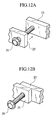
- the front headlamp bracket 25 provided on the radiator core support 5 moves further rearward relative to the headlamp 9. Motions in this case are shown in FIGS. 12A and 12B. Specifically, the front headlamp bracket 25 moves rearward from the position shown in FIG. 12A, then comes into contact with the front bracket 23 of the headlamp 9, as shown in FIG. 12B, with the front fixing bolt 26 protruding frontward from the front headlamp bracket 25.
- the front bracket 23 is fastened to the front headlamp bracket 25 of the radiator core support 5.
- the clip 29 is inserted into the clip insertion hole 27b, and the rear fixing bolt 28 is inserted into the bolt insertion hole 27a and tightened.
- the rear bracket 27 of the headlamp 9 is fastened to the rear headlamp bracket 31 of the front fender 13.
- the bolt 41 is inserted from transversely outer side into the bolt insertion hole 39a of the lower bracket 39 of the front fender 13, and screwed into the screw hole 35b of the fender bracket 35.
- the fixing block 33 of the headlamp 9 is fixed to the lower bracket 39, whereby the headlamp 9 is positioned on the front fender 13.
- the headlamp 9 is temporarily held on the radiator core support 5 in a position at the rear of the normal attachment position thereof relative to the front end module 3. Then, the front end module 3 is brought closer to the front section of the vehicle main body 1 from the front of the vehicle main body 1, to be put together with the front section. The head lamp 9 comes into contact with the front section of the vehicle main body 1 and is positioned on the front section, at a time when the front end module 3 is moved rearward. Thereafter, the headlamp 9 moves frontward relative to the radiator core support 5.
- the headlamp 9 Since the headlamp 9 is positioned on the front fender 13, affection of misalignments of the radiator core support 5, hood ridge 11, headlamp 9 and front fender 13 are eliminated.
- the headlamp 9 and the front fender 13 are aligned, and gaps and steps formed on a surface thereof can be even and smooth, improving the appearance of the front section of the vehicle body.
- the headlamp 9 can be securely positioned on the front fender 13 since the headlamp 9 is set movable relative to the front end module 3 in the state of being temporarily held.
- the headlamp 9 is incorporated in the front end module 3 while being temporarily held on the radiator core support 5. Accordingly, work of installing the headlamp 9 is eliminated, thus reducing the number of steps in the manufacturing process.
- allowable relative positional shift between the engaging positioning pin 45 and positioning hole 47a may be set smaller than that of the headlamp 9 and the front fender 13.
- a difference between the tip width W3 of the positioning pin 45 and the opening width W4 of the positioning hole 47a may be set smaller than a difference between the entrance width W2 of the guide groove 37a of the fender guide member 37 and the thickness tl of the lower bracket 39 of the front fender 13.
Abstract
Description
- The present invention relates to method and structure for positioning a headlamp on a front section of a vehicle body when assembling the vehicle body with the headlamp.
- In a process of assembling a vehicle body, a front end module which includes a radiator core support and other parts such as a bumper fascia is put together with a front section of the vehicle body. Automotive headlamps are attached to the radiator core support in the front end module.
- Japanese Patent Application Publication Laid-Open No. 2002-264745 discloses a structure, in which a bumper fascia provided with headlamp attachments, is put together with a front section of the vehicle body.
- In the aforementioned structure, the headlamps are fixed to the radiator core support, and the radiator core support is positioned on front fenders which are fixed to hood ridges in the front section of the vehicle body. Accordingly, it is difficult to adjust the alignment of the radiator core support, hood ridges, headlamps and front fenders. Misalignment thereof results in uneven gaps or steps formed on a surface, affecting the appearance of the front section of the vehicle body.
- The present invention was made in the light of this problem. An object of the present invention is to provide method and structure for properly positioning a headlamp on a front section of a vehicle body.
- An aspect of the present invention is a method for positioning a headlamp on a vehicle body, comprising: setting the headlamp temporarily in a first position on a first member of the vehicle body; and putting the first member and a second member of the vehicle body together, bringing the first member along with the headlamp closer to the second member, allowing the headlamp to move relative to the first member from the first position.
- The invention will now be described with reference to the accompanying drawings wherein:
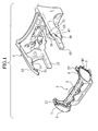
- FIG. 1 is an exploded perspective view showing a structure for positioning a headlamp on a vehicle body according to an embodiment of the present invention, in which a front end module and a front section of a vehicle body are shown apart from each other.
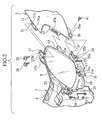
- FIG. 2 is a perspective view showing a left side of the front section of the vehicle body when the front end module is brought closer to the front section of the vehicle body, in which a temporarily holding device for the headlamp is shown.
- FIG. 3 is an enlarged perspective view of pin and hole of the temporarily holding device of FIG. 2.
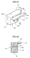
- FIG. 4A is an enlarged perspective view of a fixing block of FIG. 2.
- FIG. 4B is a cross-sectional view of the fixing block taken along line IVB-IVB of FIG. 4A.
- FIG. 5 is a perspective view showing a state where the front end module of FIG. 2 is brought closer to the front section of the vehicle body.
- FIG. 6 is an enlarged perspective view of the fixing block in FIG. 5 and a front lower end of a front fender.
- FIG. 7 is a perspective view showing a state where the front end module of FIG. 5 is brought further closer to the front section of the vehicle body.
- FIG. 8 is an enlarged perspective view of a positioning pin in FIG. 7.
- FIG. 9 is a perspective view showing a state where the front end module of FIG. 7 is brought still further closer to the front section of the vehicle body.
- FIG. 10 is a cross-sectional view of the positioning pin taken along line X-X of FIG. 9.
- FIG. 11 is an enlarged perspective view of the temporarily holding device in FIG. 9.
- FIG. 12A is an enlarged perspective view showing a relative position of a front bracket of the headlamp and a front headlamp bracket provided on the radiator core support in FIG. 5.
- FIG. 12B is an explanatory perspective view showing a relative position of the front bracket of the headlamp and the front headlamp bracket.
- An embodiment of the present invention will be explained below with reference to the drawings, wherein like members are designated by like reference characters.
- As shown in FIG. 1, a
front end module 3 is put together with a front section of a vehiclemain body 1. An assisting device or a robot with a mounting jig (not shown) for gripping thefront end module 3 may be used for bringing thefront end module 3 closer to the vehiclemain body 1. - The
front end module 3 includes aradiator core support 5 which haslamp attachments 7 on upper portions of outer ends in a vehicle transverse direction thereof.Headlamps 9 are attached onto thelamp attachments 7 in a state of being held temporarily. On both transversely outer sides of the front section of the vehiclemain body 1, there arefront fenders 13 fixed tohood ridges 11. On lower part of the front section of the vehiclemain body 1, on both transversely outer sides thereof, there arefront side members 15 extending frontward. - FIG. 2 is a perspective view showing a left side of the front section of the vehicle
main body 1 when thefront end module 3 of FIG. 1 is brought close to the front section of the vehiclemain body 1. A right side of the front section is symmetrical to the left side thereof. Description will be made only on this left side, and explanation of the right side will be omitted. - A round bar-
shaped pin 17 for temporally holding theheadlamp 9 is formed to extend downward from a lower portion of theheadlamp 9. Below theheadlamp 9, a substantially horizontalplanar portion 19 is formed on theradiator core support 5. On theplaner portion 19, ahole 21 is provided. Thepin 17 is inserted into thehole 21 and temporarily held by thehole 21. Thesepin 17 andhole 21 constitute a temporarily holding device for theheadlamp 9. - As shown in FIG. 3, the
pin 17 is formed to have agroove portion 17b having a width larger than a plate thickness of theplanar portion 19 on an outer circumferential surface thereof at a position apart from a tip portion (lower end) 17a by a predetermined distance. Moreover, thepin 17 is formed to have on the outer circumferential surface above thegroove portion 17b, adisc flange 17c extending from the outer circumferential surface. Thehole 21 is constituted of arectangular opening 21a and aholder portion 21c provided on a rear side of the opening 21a. Theholder portion 21c communicates with the opening 21a through a communicatingportion 21b, and extends rearward therefrom. - The
holder portion 21c is an inner edge of theplanar portion 19 formed in a semicircular shape, and an inner diameter thereof is set larger than an outer diameter of thegroove portion 17b of thepin 17, and smaller than an outer diameter of aportion 17d above thegroove portion 17b. Accordingly, if thegroove portion 17b of thepin 17 is inserted into and engaged with theholder portion 21c, theheadlamp 9 is temporarily held by thefront end module 3. - The communicating
portion 21b is formed to have an opening width W1 somewhat smaller than the outer diameter of thegroove portion 17b. This makes it difficult for thegroove portion 17b in theholder portion 21c to move into the opening 21a through the communicatingportion 21b. Thus, theheadlamp 9 is not released easily from the temporal holding thereof. When thegroove portion 17b is inserted into theholder portion 21c,opening edges 21d of the communicatingportion 21b are elastically deformed to some extent to allow thegroove portion 17b to get through the communicatingportion 21b. - The temporarily held
headlamp 9 is thus located in the rear of a normal attachment position thereof on thefront end module 3, and is movable frontward relative to thefront end module 3 while being kept in this state. - Moreover, the
flange 17c of thepin 17 is formed larger than the opening 21a. Thus, in case the temporal holding of theheadlamp 9 is undone, theflange 17c is caught on theplanar portion 19, preventing theheadlamp 9 from falling beyond a limited extent. - A
front bracket 23 is formed on a front part of a transversely inner side of theheadlamp 9. Theradiator core support 5 is provided with afront headlamp bracket 25, which is located in front of thefront bracket 23 of the temporarily heldheadlamp 9 at a predetermined interval. Afront fixing bolt 26 is inserted into thefront headlamp bracket 25 from the front, and a rear end of thefront fixing bolt 26 is temporarily fastened to thefront bracket 23. - On a rear part of the transversely inner side of the
headlamp 9, arear bracket 27 is provided which extends rearward. On thisrear bracket 27, abolt insertion hole 27a and aclip insertion hole 27b are made, into which arear fixing bolt 28 and aclip 29 are respectively inserted. - On an upper inner edge of the
front fender 13, arear headlamp bracket 31 formed with abolt insertion hole 31a and aclip engagement hole 31b. On a lower side of therear headlamp bracket 31, at a location corresponding to thebolt insertion hole 31a, a nut (not shown) is fixed for fastening therear fixing bolt 28 thereto. - Furthermore, a fixing
block 33 is provided on an outer lower portion of theheadlamp 9. FIG. 4A is an enlarged perspective view showing the fixingblock 33. The fixingblock 33 includes a block-shapedfender bracket 35, and a plate-shapedfender guide member 37 horizontally extending from an upper part of thefender bracket 35. - On a transversely
outer side face 35a of thefender bracket 35, ascrew hole 35b is provided. On a front lower end of thefront fender 13, alower bracket 39 is provided, on which abolt insertion hole 39a is provided. Abolt 41 is inserted into thebolt insertion hole 39a, and is fastened to thescrew hole 35b of the fixingblock 33. - The
fender guide member 37 extends from the upper portion of thefender bracket 35 transversely outward and has a part extending rearward. Aguide groove 37a is formed on thefender guide member 37 to extend frontward from a rear end thereof. Theguide groove 37a is formed on a rear end thereof with atapered notch 37b progressively widening rearward. Anentrance 37d of theguide groove 37a opens with a width W2. - The
guide groove 37a receives and guides thelower bracket 39 of thefront fender 13, which has a thickness t1. As shown in FIG. 4B, aninner sidewall 37c of theguide groove 37a and theside face 35a of thefender bracket 35 are set substantially flush with each other. - Specifically, the
fender guide member 37 guides the front edge of thelower bracket 39 of thefront fender 13 into theguide groove 37a, providing inner edges of theguide groove 37a as slidable on both transversely outer and inner sides of the vertically extendinglower bracket 39. - Moreover, the
headlamp 9 has a rear side face extending upward and rearward from a lower part thereof where the fixingblock 33 is provided. On the rear side face, apositioning pin 45 is provided to protrude rearward. Thepositioning pin 45 is tapered to have at a tip thereof a width W3 in the horizontal direction. - Meanwhile, substantially in the middle of a front edge in the vertical direction of the
front fender 13, at a location corresponding to thepositioning pin 45, apin receiver 47 is provided, which is formed to protrude transversely inward from the front edge and to have an inclined face to be matched to the aforementioned rear side face of theheadlamp 9. Thepositioning pin 45 is inserted into apositioning hole 47a with a horizontal width W4, provided on thepin receiver 47. Theheadlamp 9 is thus positioned on the vehiclemain body 1. - Next, an operation will be described. First, the
headlamp 9 is temporarily held on theradiator core support 5. This temporal holding is achieved by inserting the temporarily holdingpin 17 into theopening 21a of thehole 21, pushing thepin 17 rearward to have thegroove portion 17b of thepin 17 fitted into theholder portion 21c, as shown in FIG. 3, and inserting thefront fixing bolt 26 into thefront headlamp bracket 25, and fastening the rear end of thefront fixing bolt 26 temporarily to thefront bracket 23 of theheadlamp 9. - The
front end module 3, with theheadlamp 9 temporarily held on theradiator core support 5, is moved from the position shown in FIG. 2, and brought closer to the front section of the vehiclemain body 1. - When the
front end module 3 and the vehiclemain body 1 are brought into a state shown in FIG. 5 by the above mentioned operation, first, the front edge of thelower bracket 39 of thefront fender 13 starts entering theguide groove 37b of thefender guide member 37 as shown in FIG. 6. Specifically, thefender guide member 37 catches the front edge of thelower bracket 39 and guides thelower bracket 39 into theguide groove 37b with the inner edges thereof sliding on transversely inner and outer sides of thelower bracket 39. Here, thenotch 37b is formed at the entrance of theguide groove 37a, and accordingly, thelower bracket 39 can be easily guided to enter theguide groove 37a. - When the
front end module 3 is brought further closer to the vehiclemain body 1 from the position shown in FIG. 5, thelower bracket 39 of thefront fender 13 moves into a deep front part of theguide groove 37a as shown in FIG. 7, and then thepositioning pin 45 starts engagement with thepositioning hole 47a as shown in FIG. 8. - The
lower bracket 39 of thefront fender 13 is guided into theguide groove 37a before thepositioning pin 45 starts engagement with thepositioning hole 47a, and thepositioning pin 45 is tapered at its leading end. Accordingly, thepositioning pin 45 can easily engage with thepositioning hole 47a. - When the
front end module 3 is brought still closer to the vehiclemain body 1 from the position shown in FIG. 7, acontact face 49 provided around a base end portion of thepositioning pin 45 comes into contact with front side of thepin receiver 47 as shown in FIG. 10. Theheadlamp 9 is thus naturally positioned on the vehiclemain body 1 in the vehicle longitudinal, transverse and vertical directions. - At this moment, the
rear bracket 27 of theheadlamp 9 is placed on therear headlamp bracket 31 of thefront fender 13. Thebolt insertion holes clip insertion hole 27b and theclip engagement hole 31b are aligned to be match with each other. - When the
front end module 3 is further moved towards the vehiclemain body 1 from the position shown in FIG. 10, theheadlamp 9 moves together with the vehiclemain body 1, and accordingly theradiator core support 5 moves rearward relative to theheadlamp 9. By this relative movement, as shown in FIG. 9 and FIG. 11, the temporarily holdingpin 17 is detached from theholder portion 21c, and moves into theopening 21a. Thus, the temporal holding of theheadlamp 9 is undone. - In this case, the
flange 17c of thepin 17 is brought into contact with a peripheral edge of theopening 21a, and prevents theheadlamp 9 from falling beyond the limited extent. - With the
headlamp 9 released from the temporal holding, thefront headlamp bracket 25 provided on theradiator core support 5 moves further rearward relative to theheadlamp 9. Motions in this case are shown in FIGS. 12A and 12B. Specifically, thefront headlamp bracket 25 moves rearward from the position shown in FIG. 12A, then comes into contact with thefront bracket 23 of theheadlamp 9, as shown in FIG. 12B, with thefront fixing bolt 26 protruding frontward from thefront headlamp bracket 25. - In this state, by tightening the
front fixing bolt 26, thefront bracket 23 is fastened to thefront headlamp bracket 25 of theradiator core support 5. As shown in FIG. 9, theclip 29 is inserted into theclip insertion hole 27b, and therear fixing bolt 28 is inserted into thebolt insertion hole 27a and tightened. Thus, therear bracket 27 of theheadlamp 9 is fastened to therear headlamp bracket 31 of thefront fender 13. - Furthermore, the
bolt 41 is inserted from transversely outer side into thebolt insertion hole 39a of thelower bracket 39 of thefront fender 13, and screwed into thescrew hole 35b of thefender bracket 35. The fixingblock 33 of theheadlamp 9 is fixed to thelower bracket 39, whereby theheadlamp 9 is positioned on thefront fender 13. - According to the embodiment, the
headlamp 9 is temporarily held on theradiator core support 5 in a position at the rear of the normal attachment position thereof relative to thefront end module 3. Then, thefront end module 3 is brought closer to the front section of the vehiclemain body 1 from the front of the vehiclemain body 1, to be put together with the front section. Thehead lamp 9 comes into contact with the front section of the vehiclemain body 1 and is positioned on the front section, at a time when thefront end module 3 is moved rearward. Thereafter, theheadlamp 9 moves frontward relative to theradiator core support 5. - Since the
headlamp 9 is positioned on thefront fender 13, affection of misalignments of theradiator core support 5,hood ridge 11,headlamp 9 andfront fender 13 are eliminated. Theheadlamp 9 and thefront fender 13 are aligned, and gaps and steps formed on a surface thereof can be even and smooth, improving the appearance of the front section of the vehicle body. - Moreover, at the aforementioned positioning work, even if the
front end module 3 is somewhat deformed by weight of its own, theheadlamp 9 can be securely positioned on thefront fender 13 since theheadlamp 9 is set movable relative to thefront end module 3 in the state of being temporarily held. - Furthermore, the
headlamp 9 is incorporated in thefront end module 3 while being temporarily held on theradiator core support 5. Accordingly, work of installing theheadlamp 9 is eliminated, thus reducing the number of steps in the manufacturing process. - Moreover, when the
front end module 3 is put together with the vehiclemain body 1, the upper portions of transversely outer ends thereof are fixed to thehood ridges 11, as shown in FIG. 1, and the lower portions thereof are fixed to the front ends of thefront side members 15. - When the
front end module 3 is brought close to the vehiclemain body 1, theguide groove 37a of thefender guide member 37 and thelower bracket 39 of the front fender first start engagement with each other, before thepositioning pin 45 andpositioning hole 47a starts engagement therebetween. Therefore, allowable relative positional shift between theengaging positioning pin 45 andpositioning hole 47a may be set smaller than that of theheadlamp 9 and thefront fender 13. For example, a difference between the tip width W3 of thepositioning pin 45 and the opening width W4 of thepositioning hole 47a may be set smaller than a difference between the entrance width W2 of theguide groove 37a of thefender guide member 37 and the thickness tl of thelower bracket 39 of thefront fender 13. - The preferred embodiment described herein is illustrative and not restrictive, and the invention may be practiced or embodied in other ways without departing from the spirit or essential character thereof. The scope of the invention being indicated by the claims, and all variations which come within the meaning of claims are intended to be embraced herein.
- The present disclosure relates to subject matter contained in Japanese Patent Application No. 2003-179551, filed on June 24, 2003, the disclosure of which is expressly incorporated herein by reference in its entirety.
Claims (8)
- A method for positioning a headlamp (9) on a vehicle body, comprising:setting the headlamp (9) temporarily in a first position on a first member (3) of the vehicle body; andputting the first member (3) and a second member (1) of the vehicle body together, bringing the first member (3) along with the headlamp (9) closer to the second member (1), allowing the headlamp (9) to move relative to the first member (3) from the first position.
- The method according to claim 1, further comprising:bringing the headlamp (9) into contact with the second member (1) of the vehicle body to release the headlamp (9) from a state of being temporarily set.
- The method according to claim 1, further comprising:providing a guiding member (37) on the headlamp (9) which guides a part of the second member (1) of the vehicle body as the first member (3) is brought closer to the second member (1).
- The method according to claim 3, further comprising:providing a first positioning member (45) on the headlamp (9), and a second positioning member (47) on the second member (1) of the vehicle body, which engages with the first positioning member (45) as the first and second members (1, 3) of the vehicle body are put together,wherein the guiding member (37) on the headlamp (9) starts guiding the part of the second member (1) before engagement of the first and second positioning members (45, 47).
- A structure for positioning a headlamp (9) on a vehicle body, comprising:first and second members (1, 3) of the vehicle body, the first member (3) being brought closer to the second member (1) to be put together with the second member (1); anda holding device (17, 21) provided on the first member (3), which holds the headlamp (9) in a first position on the first member (3) as the first member (3) is brought closer to the second member (1), and allows the headlamp (9) to move relative to the first member (3) from the first position as the first member (3) is put together with the second member (1).
- The structure according to claim 5, wherein
the headlamp (9) is configured to come into contact with the second member (1) of the vehicle body to be released from the holding device (17, 21). - The structure according to claim 5, further comprising:a guiding member (37) provided on the headlamp (9) for guiding a part of the second member (1) of the vehicle body, as the first member (3) is brought closer to the second member (1).
- The structure according to claim 6, further comprising:a first positioning member (45) on the headlamp (9); anda second positioning member (47) on the second member (1) of the vehicle body, which engages with the first positioning member (45) as the first member (3) is put together with the second member (1),wherein the guiding member (37) on the headlamp (9) starts guiding the part of the second member (1) before engagement of the first and second positioning members (45, 47).
Applications Claiming Priority (2)
| Application Number | Priority Date | Filing Date | Title |
|---|---|---|---|
| JP2003179551A JP3843968B2 (en) | 2003-06-24 | 2003-06-24 | Headlamp body positioning method and body positioning structure |
| JP2003179551 | 2003-06-24 |
Publications (3)
| Publication Number | Publication Date |
|---|---|
| EP1491401A2 true EP1491401A2 (en) | 2004-12-29 |
| EP1491401A3 EP1491401A3 (en) | 2005-11-30 |
| EP1491401B1 EP1491401B1 (en) | 2008-09-10 |
Family
ID=33411057
Family Applications (1)
| Application Number | Title | Priority Date | Filing Date |
|---|---|---|---|
| EP04013682A Expired - Fee Related EP1491401B1 (en) | 2003-06-24 | 2004-06-09 | Method and structure for positioning headlamp on vehicle body |
Country Status (6)
| Country | Link |
|---|---|
| US (1) | US7338191B2 (en) |
| EP (1) | EP1491401B1 (en) |
| JP (1) | JP3843968B2 (en) |
| KR (1) | KR100570719B1 (en) |
| CN (1) | CN1313311C (en) |
| DE (1) | DE602004016420D1 (en) |
Cited By (16)
| Publication number | Priority date | Publication date | Assignee | Title |
|---|---|---|---|---|
| DE102006008240A1 (en) * | 2006-02-22 | 2007-08-23 | Volkswagen Ag | Mounting device for head light on vehicle, has mounting part connected with upper longitudinal carrier and another mounting part connected with front end assembly carrier of vehicle |
| JP2007297041A (en) * | 2006-05-05 | 2007-11-15 | Nissan Motor Manufacturing (Uk) Ltd | Improvement method of rigidity of body panel for vehicle |
| EP1939076A1 (en) * | 2006-12-29 | 2008-07-02 | Automotive Lighting Italia Spa | Method of manufacture of headlights for the precision assembly of the same on vehicles |
| FR2921333A1 (en) * | 2007-09-25 | 2009-03-27 | Peugeot Citroen Automobiles Sa | MOTOR VEHICLE WITH REDUCED GAMES AND AFFLEMENTS |
| FR2932437A1 (en) * | 2008-06-17 | 2009-12-18 | Peugeot Citroen Automobiles Sa | Optical block i.e. right tail light, indexing device for motor vehicle, has selector forks guiding positioning of casing in reception opening of optical block by insertion of two indexation tabs between branches of forks, respectively |
| WO2010001037A2 (en) * | 2008-07-01 | 2010-01-07 | Renault S.A.S. | Arrangement for motor vehicle front part |
| FR2934557A1 (en) * | 2008-08-04 | 2010-02-05 | Peugeot Citroen Automobiles Sa | SYSTEM FOR INDEXING A LIGHTING ORGAN ON A MOTOR VEHICLE. |
| GB2437719B (en) * | 2006-05-05 | 2010-12-29 | Nissan Motor Mfg | Body panel insert |
| FR2971466A1 (en) * | 2011-02-14 | 2012-08-17 | Peugeot Citroen Automobiles Sa | Device for assembling and disassembling e.g. front left headlight on car body, has indexing units indexing headlight on zones and surrounding parts of wing, and permitting headlight to be assembled/disassembled along longitudinal direction |
| FR3038289A1 (en) * | 2015-07-03 | 2017-01-06 | Peugeot Citroen Automobiles Sa | FRONT PROJECTOR FOR A MOTOR VEHICLE WITH A CASING COMPRISING A LOWER ANCHOR ELEMENT |
| FR3051412A1 (en) * | 2016-05-23 | 2017-11-24 | Peugeot Citroen Automobiles Sa | LIGHTING AND / OR SIGNALING DEVICE FOR A MOTOR VEHICLE FOR IMPLANTING IN A BODY COMPONENT |
| GB2554396A (en) * | 2016-09-26 | 2018-04-04 | Jaguar Land Rover Ltd | Lamp assembly, method of installing a lamp assembly, method of manufacturing sets of lamp assemblies, and a vehicle comprising a lamp assembly |
| GB2559980A (en) * | 2017-02-23 | 2018-08-29 | Jaguar Land Rover Ltd | Motor vehicle lamp fender alignement assembly |
| GB2560929A (en) * | 2017-03-28 | 2018-10-03 | Jaguar Land Rover Ltd | A bracket for mounting a lamp housing to a motor vehicle |
| FR3065703A1 (en) * | 2017-04-28 | 2018-11-02 | Peugeot Citroen Automobiles Sa | ARRANGEMENT FOR A MOTOR VEHICLE COMPRISING A BODY MEMBER AND A LIGHTING AND / OR SIGNALING DEVICE IMPLANTED IN SAID BODY ELEMENT. |
| EP3623267A1 (en) * | 2018-09-12 | 2020-03-18 | Motherson Innovations Company Limited | Device for adjusting a first component and a second component of a pedestrian and/or goods transport means relative to each other, and passenger and/or goods transport means with such a device |
Families Citing this family (27)
| Publication number | Priority date | Publication date | Assignee | Title |
|---|---|---|---|---|
| JP4432516B2 (en) * | 2004-02-06 | 2010-03-17 | 日産自動車株式会社 | Body front structure |
| FR2873649B1 (en) * | 2004-08-02 | 2006-11-24 | Faurecia Bloc Avant | FRONT BLOCK ASSEMBLY OF MOTOR VEHICLE |
| JP4186227B2 (en) * | 2004-12-28 | 2008-11-26 | 株式会社ホンダアクセス | Vehicle component mounting hole positioning jig |
| KR100728724B1 (en) * | 2005-07-05 | 2007-06-14 | 현대모비스 주식회사 | Head lamp |
| FR2888197B1 (en) * | 2005-07-08 | 2007-10-12 | Faurecia Bloc Avant | FRONT BLOCK ASSEMBLY OF A CORRESPONDING MOTOR VEHICLE. |
| JP4797512B2 (en) * | 2005-08-25 | 2011-10-19 | スズキ株式会社 | Vehicle front structure |
| FR2914618B1 (en) * | 2007-04-03 | 2009-09-18 | Renault Sas | METHOD FOR MOUNTING A CROSS-SECTIONAL ELEMENT AND A TECHNICAL FRONT PANEL |
| US7987937B2 (en) | 2007-06-12 | 2011-08-02 | Chrysler Group Llc | Systems and methods for assembling a front end module to a vehicle |
| KR100936979B1 (en) * | 2007-11-30 | 2010-01-15 | 현대자동차주식회사 | Front end module of a vehicle |
| JP4445545B2 (en) | 2007-12-21 | 2010-04-07 | カルソニックカンセイ株式会社 | Headlamp mounting structure |
| US7644966B2 (en) * | 2008-02-29 | 2010-01-12 | Nissan Technical Center North America, Inc. | Vehicle bumper fascia retainer |
| FR2943609B1 (en) * | 2009-03-25 | 2011-06-10 | Renault Sas | ARRANGEMENT FOR A FRONT PART OF A MOTOR VEHICLE |
| US20110032719A1 (en) * | 2009-08-05 | 2011-02-10 | Toyota Motor Engineering & Manufacturing North America, Inc. | Control device for controlling the position of a bumper fascia |
| DE102010011238A1 (en) * | 2010-03-12 | 2011-09-15 | GM Global Technology Operations LLC , (n. d. Ges. d. Staates Delaware) | Assembly unit for a motor vehicle and method for providing reference positions for the mounting unit |
| RU2566828C2 (en) * | 2011-03-07 | 2015-10-27 | Фаурециа Экстериорс Гмбх | Multifunctional mounting for vehicle |
| CN102358229A (en) * | 2011-07-29 | 2012-02-22 | 奇瑞汽车股份有限公司 | Automotive headlamp bracket |
| CN102490137B (en) * | 2011-12-13 | 2014-07-30 | 奇瑞汽车股份有限公司 | Centering and positioning fixture for automobile assembly |
| FR2985472B1 (en) * | 2012-01-09 | 2015-02-27 | Peugeot Citroen Automobiles Sa | FRONT PROJECTOR FOR MOTOR VEHICLE |
| CN103802721B (en) * | 2012-11-06 | 2017-11-21 | 标致雪铁龙(中国)汽车贸易有限公司 | A kind of erecting device and its installation method for automobile front lamp component |
| US8720975B1 (en) * | 2012-12-19 | 2014-05-13 | Ford Global Technologies, Llc | Integrated hood bump-stop and headlamp attachment for pedestrian protection |
| DE102013220574A1 (en) * | 2013-10-11 | 2015-04-16 | Bayerische Motoren Werke Aktiengesellschaft | Method for mounting a front end module and a headlight on a body of a passenger car and holding arrangement of a headlight on a front end module |
| GB2525227B (en) * | 2014-04-16 | 2016-09-14 | Jaguar Land Rover Ltd | Bumper assembly method and apparatus |
| US10450018B2 (en) | 2017-01-04 | 2019-10-22 | Ford Global Technologies, Llc | Loose layered build components and vehicle front end assembly strategy |
| US10704756B2 (en) | 2017-01-04 | 2020-07-07 | Ford Global Technologies, Llc | Loose layered build components and vehicle front end assembly strategy |
| US10272819B2 (en) | 2017-01-04 | 2019-04-30 | Ford Global Technologies, Llc | Loose layered build components and vehicle front end assembly strategy |
| US10093272B1 (en) * | 2017-06-12 | 2018-10-09 | Toyota Motor Engineering & Manufacturing North America, Inc. | Front end assemblies having reinforcement brackets |
| US10843640B2 (en) * | 2018-12-14 | 2020-11-24 | Ford Global Technologies, Llc | Vehicle with locator device configured to maintain outer body panel alignment, and corresponding method |
Citations (4)
| Publication number | Priority date | Publication date | Assignee | Title |
|---|---|---|---|---|
| US4636921A (en) * | 1984-05-09 | 1987-01-13 | Audi Ag | Device for mounting a light unit on an automobile body |
| DE19946995A1 (en) * | 1998-09-30 | 2000-04-13 | Ecia Equip Composants Ind Auto | Front panel of a motor vehicle incorporating head lamps within the assembly |
| EP1024075A1 (en) * | 1999-01-26 | 2000-08-02 | MAGNETI MARELLI CLIMATIZZAZIONE S.p.A. | Preassembled frontal assembly for vehicles |
| EP1270387A1 (en) * | 2001-06-20 | 2003-01-02 | Nissan Motor Company, Limited | Method for assemblying vehicle body |
Family Cites Families (15)
| Publication number | Priority date | Publication date | Assignee | Title |
|---|---|---|---|---|
| JPS6075136U (en) | 1983-10-31 | 1985-05-27 | 日産自動車株式会社 | Vehicle lamp mounting structure |
| JPH048029Y2 (en) | 1987-02-04 | 1992-03-02 | ||
| US5358304A (en) * | 1989-12-21 | 1994-10-25 | Mazda Motor Corporation | Front body structure of a vehicle and assembling method |
| DE4437083C2 (en) * | 1993-10-25 | 1996-10-17 | Fuji Heavy Ind Ltd | Module support structure |
| JP2000072034A (en) | 1998-08-26 | 2000-03-07 | Aisin Seiki Co Ltd | Vehicular front end module structure and assembly method therefor |
| FR2787410B1 (en) * | 1998-12-21 | 2001-03-09 | Ecia Equip Composants Ind Auto | FRONT PANEL AND ARRANGEMENT OF THE FRONT PANEL IN A MOTOR VEHICLE |
| JP3697976B2 (en) * | 1999-03-16 | 2005-09-21 | 日産自動車株式会社 | Front end module mounting structure |
| JP2001010534A (en) | 1999-06-24 | 2001-01-16 | Nissan Motor Co Ltd | Automotive front end module structure |
| JP2002264745A (en) | 2001-03-08 | 2002-09-18 | Calsonic Kansei Corp | Car body front structure of automobile |
| JP3891007B2 (en) | 2001-04-23 | 2007-03-07 | 日産自動車株式会社 | Front body structure of automobile and assembly method of front body |
| JP2002326585A (en) | 2001-05-02 | 2002-11-12 | Daihatsu Motor Co Ltd | Body front structure of car |
| JP2002370574A (en) | 2001-06-18 | 2002-12-24 | Mitsubishi Motors Corp | Vehicular front structure |
| JP2003095011A (en) | 2001-09-20 | 2003-04-03 | Calsonic Kansei Corp | Manufacturing method and fitting method of front end module of vehicle |
| WO2003074347A1 (en) * | 2002-03-01 | 2003-09-12 | Nissan Motor Co., Ltd. | Automobile car body front construction and method of assembling car body front |
| JP3915559B2 (en) * | 2002-03-14 | 2007-05-16 | 日産自動車株式会社 | Car headlamp mounting structure |
-
2003
- 2003-06-24 JP JP2003179551A patent/JP3843968B2/en not_active Expired - Fee Related
-
2004
- 2004-06-09 EP EP04013682A patent/EP1491401B1/en not_active Expired - Fee Related
- 2004-06-09 DE DE602004016420T patent/DE602004016420D1/en active Active
- 2004-06-18 US US10/870,151 patent/US7338191B2/en not_active Expired - Fee Related
- 2004-06-22 KR KR1020040046541A patent/KR100570719B1/en not_active IP Right Cessation
- 2004-06-24 CN CNB2004100628426A patent/CN1313311C/en not_active Expired - Fee Related
Patent Citations (4)
| Publication number | Priority date | Publication date | Assignee | Title |
|---|---|---|---|---|
| US4636921A (en) * | 1984-05-09 | 1987-01-13 | Audi Ag | Device for mounting a light unit on an automobile body |
| DE19946995A1 (en) * | 1998-09-30 | 2000-04-13 | Ecia Equip Composants Ind Auto | Front panel of a motor vehicle incorporating head lamps within the assembly |
| EP1024075A1 (en) * | 1999-01-26 | 2000-08-02 | MAGNETI MARELLI CLIMATIZZAZIONE S.p.A. | Preassembled frontal assembly for vehicles |
| EP1270387A1 (en) * | 2001-06-20 | 2003-01-02 | Nissan Motor Company, Limited | Method for assemblying vehicle body |
Cited By (25)
| Publication number | Priority date | Publication date | Assignee | Title |
|---|---|---|---|---|
| DE102006008240A1 (en) * | 2006-02-22 | 2007-08-23 | Volkswagen Ag | Mounting device for head light on vehicle, has mounting part connected with upper longitudinal carrier and another mounting part connected with front end assembly carrier of vehicle |
| GB2437719B (en) * | 2006-05-05 | 2010-12-29 | Nissan Motor Mfg | Body panel insert |
| JP2007297041A (en) * | 2006-05-05 | 2007-11-15 | Nissan Motor Manufacturing (Uk) Ltd | Improvement method of rigidity of body panel for vehicle |
| EP1852334A3 (en) * | 2006-05-05 | 2008-07-02 | Nissan Motor Manufacturing (Uk) Ltd | Improving the Rigidity of Vehicle Body Panels |
| EP1939076A1 (en) * | 2006-12-29 | 2008-07-02 | Automotive Lighting Italia Spa | Method of manufacture of headlights for the precision assembly of the same on vehicles |
| FR2921333A1 (en) * | 2007-09-25 | 2009-03-27 | Peugeot Citroen Automobiles Sa | MOTOR VEHICLE WITH REDUCED GAMES AND AFFLEMENTS |
| EP2042413A1 (en) * | 2007-09-25 | 2009-04-01 | Peugeot Citroen Automobiles SA | Automobile with reduced clearance and flushing. |
| FR2932437A1 (en) * | 2008-06-17 | 2009-12-18 | Peugeot Citroen Automobiles Sa | Optical block i.e. right tail light, indexing device for motor vehicle, has selector forks guiding positioning of casing in reception opening of optical block by insertion of two indexation tabs between branches of forks, respectively |
| FR2933371A1 (en) * | 2008-07-01 | 2010-01-08 | Renault Sas | ARRANGEMENT FOR A FRONT PART OF A MOTOR VEHICLE |
| WO2010001037A3 (en) * | 2008-07-01 | 2010-03-04 | Renault S.A.S. | Arrangement for motor vehicle front part |
| WO2010001037A2 (en) * | 2008-07-01 | 2010-01-07 | Renault S.A.S. | Arrangement for motor vehicle front part |
| FR2934557A1 (en) * | 2008-08-04 | 2010-02-05 | Peugeot Citroen Automobiles Sa | SYSTEM FOR INDEXING A LIGHTING ORGAN ON A MOTOR VEHICLE. |
| EP2154024A1 (en) * | 2008-08-04 | 2010-02-17 | Peugeot Citroën Automobiles Sa | Indexing system of an automotive lighting element |
| FR2971466A1 (en) * | 2011-02-14 | 2012-08-17 | Peugeot Citroen Automobiles Sa | Device for assembling and disassembling e.g. front left headlight on car body, has indexing units indexing headlight on zones and surrounding parts of wing, and permitting headlight to be assembled/disassembled along longitudinal direction |
| FR3038289A1 (en) * | 2015-07-03 | 2017-01-06 | Peugeot Citroen Automobiles Sa | FRONT PROJECTOR FOR A MOTOR VEHICLE WITH A CASING COMPRISING A LOWER ANCHOR ELEMENT |
| WO2017006011A1 (en) * | 2015-07-03 | 2017-01-12 | Peugeot Citroen Automobiles Sa | Motor vehicle front headlamp equipped with a casing comprising a lower anchoring element |
| FR3051412A1 (en) * | 2016-05-23 | 2017-11-24 | Peugeot Citroen Automobiles Sa | LIGHTING AND / OR SIGNALING DEVICE FOR A MOTOR VEHICLE FOR IMPLANTING IN A BODY COMPONENT |
| GB2554396A (en) * | 2016-09-26 | 2018-04-04 | Jaguar Land Rover Ltd | Lamp assembly, method of installing a lamp assembly, method of manufacturing sets of lamp assemblies, and a vehicle comprising a lamp assembly |
| GB2554396B (en) * | 2016-09-26 | 2019-05-22 | Jaguar Land Rover Ltd | Lamp assembly, method of installing a lamp assembly, method of manufacturing sets of lamp assemblies, and a vehicle comprising a lamp assembly |
| GB2559980A (en) * | 2017-02-23 | 2018-08-29 | Jaguar Land Rover Ltd | Motor vehicle lamp fender alignement assembly |
| GB2559980B (en) * | 2017-02-23 | 2019-10-30 | Jaguar Land Rover Ltd | Motor vehicle lamp fender alignement assembly |
| GB2560929A (en) * | 2017-03-28 | 2018-10-03 | Jaguar Land Rover Ltd | A bracket for mounting a lamp housing to a motor vehicle |
| FR3065703A1 (en) * | 2017-04-28 | 2018-11-02 | Peugeot Citroen Automobiles Sa | ARRANGEMENT FOR A MOTOR VEHICLE COMPRISING A BODY MEMBER AND A LIGHTING AND / OR SIGNALING DEVICE IMPLANTED IN SAID BODY ELEMENT. |
| EP3623267A1 (en) * | 2018-09-12 | 2020-03-18 | Motherson Innovations Company Limited | Device for adjusting a first component and a second component of a pedestrian and/or goods transport means relative to each other, and passenger and/or goods transport means with such a device |
| CN110894843A (en) * | 2018-09-12 | 2020-03-20 | 玛泽森创新有限公司 | Device for adjusting a first component and a second component relative to each other |
Also Published As
| Publication number | Publication date |
|---|---|
| US20040264203A1 (en) | 2004-12-30 |
| CN1313311C (en) | 2007-05-02 |
| DE602004016420D1 (en) | 2008-10-23 |
| JP3843968B2 (en) | 2006-11-08 |
| EP1491401B1 (en) | 2008-09-10 |
| KR100570719B1 (en) | 2006-04-12 |
| EP1491401A3 (en) | 2005-11-30 |
| US7338191B2 (en) | 2008-03-04 |
| CN1572637A (en) | 2005-02-02 |
| JP2005014665A (en) | 2005-01-20 |
| KR20050001349A (en) | 2005-01-06 |
Similar Documents
| Publication | Publication Date | Title |
|---|---|---|
| EP1491401B1 (en) | Method and structure for positioning headlamp on vehicle body | |
| US6592164B2 (en) | Automotive exterior member mounting construction and automobile | |
| JP5018012B2 (en) | Bumper mounting structure | |
| EP0826560B1 (en) | Bumper face and attaching method of bumper face | |
| EP1580099B1 (en) | Front end module assembly structure | |
| EP1561638B1 (en) | Vehicle front body structure | |
| US20020008399A1 (en) | Automotive dash module installation structure and method of installing same | |
| US8231091B2 (en) | Clip and mounting structure for mounting an automotive bumper accessory component | |
| JP5724115B2 (en) | Vehicle outfitting parts and mounting structure thereof | |
| JP5947321B2 (en) | Bumper mounting structure | |
| JP2509930Y2 (en) | Resin bumper harness fixed structure | |
| JPH0530500Y2 (en) | ||
| KR20080024689A (en) | Mounting structure of bumper cover for automobile | |
| JP5088120B2 (en) | Electrical junction box | |
| JP5613959B2 (en) | Vehicle rear bumper mounting structure | |
| KR0175123B1 (en) | A detachable structure of a car audio | |
| JPS6368477A (en) | Front seat attaching structure for vehicle | |
| JPH04249633A (en) | Simple installation bracket for stay damper | |
| KR200154224Y1 (en) | Head lamp housing | |
| JPH0336440Y2 (en) | ||
| JP3262763B2 (en) | Lamp mounting structure and mounting method for vehicle bumper | |
| CN112172660A (en) | Lamp body mounting structure | |
| JP5334790B2 (en) | Vehicle lamp device | |
| JP2023007798A (en) | Striker mounting jig and striker mounting method | |
| JP5120236B2 (en) | Assembly structure of center lower panel in vehicle instrument panel |
Legal Events
| Date | Code | Title | Description |
|---|---|---|---|
| PUAI | Public reference made under article 153(3) epc to a published international application that has entered the european phase |
Free format text: ORIGINAL CODE: 0009012 |
|
| 17P | Request for examination filed |
Effective date: 20040609 |
|
| AK | Designated contracting states |
Kind code of ref document: A2 Designated state(s): AT BE BG CH CY CZ DE DK EE ES FI FR GB GR HU IE IT LI LU MC NL PL PT RO SE SI SK TR |
|
| AX | Request for extension of the european patent |
Extension state: AL HR LT LV MK |
|
| TPAC | Observations by third parties |
Free format text: ORIGINAL CODE: EPIDOSNTIPA |
|
| PUAL | Search report despatched |
Free format text: ORIGINAL CODE: 0009013 |
|
| AK | Designated contracting states |
Kind code of ref document: A3 Designated state(s): AT BE BG CH CY CZ DE DK EE ES FI FR GB GR HU IE IT LI LU MC NL PL PT RO SE SI SK TR |
|
| AX | Request for extension of the european patent |
Extension state: AL HR LT LV MK |
|
| AKX | Designation fees paid |
Designated state(s): DE FR GB |
|
| GRAP | Despatch of communication of intention to grant a patent |
Free format text: ORIGINAL CODE: EPIDOSNIGR1 |
|
| RIN1 | Information on inventor provided before grant (corrected) |
Inventor name: TAKII, HIROKI Inventor name: KONNO, ISAO |
|
| GRAS | Grant fee paid |
Free format text: ORIGINAL CODE: EPIDOSNIGR3 |
|
| GRAA | (expected) grant |
Free format text: ORIGINAL CODE: 0009210 |
|
| AK | Designated contracting states |
Kind code of ref document: B1 Designated state(s): DE FR GB |
|
| REG | Reference to a national code |
Ref country code: GB Ref legal event code: FG4D |
|
| REF | Corresponds to: |
Ref document number: 602004016420 Country of ref document: DE Date of ref document: 20081023 Kind code of ref document: P |
|
| PLBE | No opposition filed within time limit |
Free format text: ORIGINAL CODE: 0009261 |
|
| STAA | Information on the status of an ep patent application or granted ep patent |
Free format text: STATUS: NO OPPOSITION FILED WITHIN TIME LIMIT |
|
| 26N | No opposition filed |
Effective date: 20090611 |
|
| PGFP | Annual fee paid to national office [announced via postgrant information from national office to epo] |
Ref country code: FR Payment date: 20110621 Year of fee payment: 8 |
|
| PGFP | Annual fee paid to national office [announced via postgrant information from national office to epo] |
Ref country code: GB Payment date: 20110608 Year of fee payment: 8 |
|
| PGFP | Annual fee paid to national office [announced via postgrant information from national office to epo] |
Ref country code: DE Payment date: 20110601 Year of fee payment: 8 |
|
| GBPC | Gb: european patent ceased through non-payment of renewal fee |
Effective date: 20120609 |
|
| REG | Reference to a national code |
Ref country code: FR Ref legal event code: ST Effective date: 20130228 |
|
| REG | Reference to a national code |
Ref country code: DE Ref legal event code: R119 Ref document number: 602004016420 Country of ref document: DE Effective date: 20130101 |
|
| PG25 | Lapsed in a contracting state [announced via postgrant information from national office to epo] |
Ref country code: GB Free format text: LAPSE BECAUSE OF NON-PAYMENT OF DUE FEES Effective date: 20120609 Ref country code: FR Free format text: LAPSE BECAUSE OF NON-PAYMENT OF DUE FEES Effective date: 20120702 Ref country code: DE Free format text: LAPSE BECAUSE OF NON-PAYMENT OF DUE FEES Effective date: 20130101 |