EP1490587B1 - Engine system - Google Patents
Engine system Download PDFInfo
- Publication number
- EP1490587B1 EP1490587B1 EP03710179A EP03710179A EP1490587B1 EP 1490587 B1 EP1490587 B1 EP 1490587B1 EP 03710179 A EP03710179 A EP 03710179A EP 03710179 A EP03710179 A EP 03710179A EP 1490587 B1 EP1490587 B1 EP 1490587B1
- Authority
- EP
- European Patent Office
- Prior art keywords
- volumetric
- devices
- fluid
- engine system
- discharge
- Prior art date
- Legal status (The legal status is an assumption and is not a legal conclusion. Google has not performed a legal analysis and makes no representation as to the accuracy of the status listed.)
- Expired - Lifetime
Links
- 239000012530 fluid Substances 0.000 claims abstract description 77
- 238000006073 displacement reaction Methods 0.000 claims description 25
- 239000000446 fuel Substances 0.000 claims description 12
- 238000001816 cooling Methods 0.000 claims description 10
- 230000005540 biological transmission Effects 0.000 claims description 7
- 230000007246 mechanism Effects 0.000 claims description 6
- 238000004891 communication Methods 0.000 claims description 5
- 238000010438 heat treatment Methods 0.000 claims description 5
- 230000004044 response Effects 0.000 claims description 3
- 230000004913 activation Effects 0.000 claims description 2
- 230000009849 deactivation Effects 0.000 claims description 2
- 230000000754 repressing effect Effects 0.000 claims 1
- 239000003570 air Substances 0.000 description 23
- 239000007789 gas Substances 0.000 description 20
- 239000000872 buffer Substances 0.000 description 16
- 239000000567 combustion gas Substances 0.000 description 12
- 238000002485 combustion reaction Methods 0.000 description 9
- 230000008901 benefit Effects 0.000 description 8
- 238000010586 diagram Methods 0.000 description 8
- 238000000034 method Methods 0.000 description 4
- 230000002093 peripheral effect Effects 0.000 description 4
- 230000008569 process Effects 0.000 description 4
- 230000009467 reduction Effects 0.000 description 4
- 230000008878 coupling Effects 0.000 description 3
- 238000010168 coupling process Methods 0.000 description 3
- 238000005859 coupling reaction Methods 0.000 description 3
- 125000004122 cyclic group Chemical group 0.000 description 3
- 230000006870 function Effects 0.000 description 3
- 239000000203 mixture Substances 0.000 description 3
- 239000012080 ambient air Substances 0.000 description 2
- QVGXLLKOCUKJST-UHFFFAOYSA-N atomic oxygen Chemical compound [O] QVGXLLKOCUKJST-UHFFFAOYSA-N 0.000 description 2
- 230000006835 compression Effects 0.000 description 2
- 238000007906 compression Methods 0.000 description 2
- 239000001301 oxygen Substances 0.000 description 2
- 229910052760 oxygen Inorganic materials 0.000 description 2
- 230000003068 static effect Effects 0.000 description 2
- 230000003213 activating effect Effects 0.000 description 1
- 230000006978 adaptation Effects 0.000 description 1
- 230000003416 augmentation Effects 0.000 description 1
- 230000008859 change Effects 0.000 description 1
- 230000007812 deficiency Effects 0.000 description 1
- 230000003467 diminishing effect Effects 0.000 description 1
- 238000007599 discharging Methods 0.000 description 1
- 230000003071 parasitic effect Effects 0.000 description 1
- 238000007789 sealing Methods 0.000 description 1
- 238000011144 upstream manufacturing Methods 0.000 description 1
Images


Classifications
-
- F—MECHANICAL ENGINEERING; LIGHTING; HEATING; WEAPONS; BLASTING
- F01—MACHINES OR ENGINES IN GENERAL; ENGINE PLANTS IN GENERAL; STEAM ENGINES
- F01C—ROTARY-PISTON OR OSCILLATING-PISTON MACHINES OR ENGINES
- F01C1/00—Rotary-piston machines or engines
- F01C1/08—Rotary-piston machines or engines of intermeshing engagement type, i.e. with engagement of co- operating members similar to that of toothed gearing
- F01C1/12—Rotary-piston machines or engines of intermeshing engagement type, i.e. with engagement of co- operating members similar to that of toothed gearing of other than internal-axis type
- F01C1/14—Rotary-piston machines or engines of intermeshing engagement type, i.e. with engagement of co- operating members similar to that of toothed gearing of other than internal-axis type with toothed rotary pistons
- F01C1/20—Rotary-piston machines or engines of intermeshing engagement type, i.e. with engagement of co- operating members similar to that of toothed gearing of other than internal-axis type with toothed rotary pistons with dissimilar tooth forms
-
- F—MECHANICAL ENGINEERING; LIGHTING; HEATING; WEAPONS; BLASTING
- F01—MACHINES OR ENGINES IN GENERAL; ENGINE PLANTS IN GENERAL; STEAM ENGINES
- F01C—ROTARY-PISTON OR OSCILLATING-PISTON MACHINES OR ENGINES
- F01C1/00—Rotary-piston machines or engines
- F01C1/22—Rotary-piston machines or engines of internal-axis type with equidirectional movement of co-operating members at the points of engagement, or with one of the co-operating members being stationary, the inner member having more teeth or tooth- equivalents than the outer member
-
- F—MECHANICAL ENGINEERING; LIGHTING; HEATING; WEAPONS; BLASTING
- F01—MACHINES OR ENGINES IN GENERAL; ENGINE PLANTS IN GENERAL; STEAM ENGINES
- F01C—ROTARY-PISTON OR OSCILLATING-PISTON MACHINES OR ENGINES
- F01C11/00—Combinations of two or more machines or engines, each being of rotary-piston or oscillating-piston type
- F01C11/002—Combinations of two or more machines or engines, each being of rotary-piston or oscillating-piston type of similar working principle
- F01C11/004—Combinations of two or more machines or engines, each being of rotary-piston or oscillating-piston type of similar working principle and of complementary function, e.g. internal combustion engine with supercharger
-
- F—MECHANICAL ENGINEERING; LIGHTING; HEATING; WEAPONS; BLASTING
- F01—MACHINES OR ENGINES IN GENERAL; ENGINE PLANTS IN GENERAL; STEAM ENGINES
- F01C—ROTARY-PISTON OR OSCILLATING-PISTON MACHINES OR ENGINES
- F01C11/00—Combinations of two or more machines or engines, each being of rotary-piston or oscillating-piston type
- F01C11/006—Combinations of two or more machines or engines, each being of rotary-piston or oscillating-piston type of dissimilar working principle
- F01C11/008—Combinations of two or more machines or engines, each being of rotary-piston or oscillating-piston type of dissimilar working principle and of complementary function, e.g. internal combustion engine with supercharger
-
- F—MECHANICAL ENGINEERING; LIGHTING; HEATING; WEAPONS; BLASTING
- F02—COMBUSTION ENGINES; HOT-GAS OR COMBUSTION-PRODUCT ENGINE PLANTS
- F02B—INTERNAL-COMBUSTION PISTON ENGINES; COMBUSTION ENGINES IN GENERAL
- F02B41/00—Engines characterised by special means for improving conversion of heat or pressure energy into mechanical power
- F02B41/02—Engines with prolonged expansion
- F02B41/10—Engines with prolonged expansion in exhaust turbines
-
- F—MECHANICAL ENGINEERING; LIGHTING; HEATING; WEAPONS; BLASTING
- F02—COMBUSTION ENGINES; HOT-GAS OR COMBUSTION-PRODUCT ENGINE PLANTS
- F02B—INTERNAL-COMBUSTION PISTON ENGINES; COMBUSTION ENGINES IN GENERAL
- F02B53/00—Internal-combustion aspects of rotary-piston or oscillating-piston engines
-
- F—MECHANICAL ENGINEERING; LIGHTING; HEATING; WEAPONS; BLASTING
- F02—COMBUSTION ENGINES; HOT-GAS OR COMBUSTION-PRODUCT ENGINE PLANTS
- F02B—INTERNAL-COMBUSTION PISTON ENGINES; COMBUSTION ENGINES IN GENERAL
- F02B53/00—Internal-combustion aspects of rotary-piston or oscillating-piston engines
- F02B53/14—Adaptations of engines for driving, or engine combinations with, other devices
-
- F—MECHANICAL ENGINEERING; LIGHTING; HEATING; WEAPONS; BLASTING
- F02—COMBUSTION ENGINES; HOT-GAS OR COMBUSTION-PRODUCT ENGINE PLANTS
- F02C—GAS-TURBINE PLANTS; AIR INTAKES FOR JET-PROPULSION PLANTS; CONTROLLING FUEL SUPPLY IN AIR-BREATHING JET-PROPULSION PLANTS
- F02C3/00—Gas-turbine plants characterised by the use of combustion products as the working fluid
- F02C3/04—Gas-turbine plants characterised by the use of combustion products as the working fluid having a turbine driving a compressor
- F02C3/055—Gas-turbine plants characterised by the use of combustion products as the working fluid having a turbine driving a compressor the compressor being of the positive-displacement type
-
- F—MECHANICAL ENGINEERING; LIGHTING; HEATING; WEAPONS; BLASTING
- F02—COMBUSTION ENGINES; HOT-GAS OR COMBUSTION-PRODUCT ENGINE PLANTS
- F02G—HOT GAS OR COMBUSTION-PRODUCT POSITIVE-DISPLACEMENT ENGINE PLANTS; USE OF WASTE HEAT OF COMBUSTION ENGINES; NOT OTHERWISE PROVIDED FOR
- F02G1/00—Hot gas positive-displacement engine plants
- F02G1/02—Hot gas positive-displacement engine plants of open-cycle type
-
- F—MECHANICAL ENGINEERING; LIGHTING; HEATING; WEAPONS; BLASTING
- F02—COMBUSTION ENGINES; HOT-GAS OR COMBUSTION-PRODUCT ENGINE PLANTS
- F02K—JET-PROPULSION PLANTS
- F02K5/00—Plants including an engine, other than a gas turbine, driving a compressor or a ducted fan
-
- F—MECHANICAL ENGINEERING; LIGHTING; HEATING; WEAPONS; BLASTING
- F03—MACHINES OR ENGINES FOR LIQUIDS; WIND, SPRING, OR WEIGHT MOTORS; PRODUCING MECHANICAL POWER OR A REACTIVE PROPULSIVE THRUST, NOT OTHERWISE PROVIDED FOR
- F03C—POSITIVE-DISPLACEMENT ENGINES DRIVEN BY LIQUIDS
- F03C2/00—Rotary-piston engines
- F03C2/08—Rotary-piston engines of intermeshing-engagement type, i.e. with engagement of co- operating members similar to that of toothed gearing
-
- F—MECHANICAL ENGINEERING; LIGHTING; HEATING; WEAPONS; BLASTING
- F02—COMBUSTION ENGINES; HOT-GAS OR COMBUSTION-PRODUCT ENGINE PLANTS
- F02B—INTERNAL-COMBUSTION PISTON ENGINES; COMBUSTION ENGINES IN GENERAL
- F02B53/00—Internal-combustion aspects of rotary-piston or oscillating-piston engines
- F02B2053/005—Wankel engines
-
- F—MECHANICAL ENGINEERING; LIGHTING; HEATING; WEAPONS; BLASTING
- F02—COMBUSTION ENGINES; HOT-GAS OR COMBUSTION-PRODUCT ENGINE PLANTS
- F02G—HOT GAS OR COMBUSTION-PRODUCT POSITIVE-DISPLACEMENT ENGINE PLANTS; USE OF WASTE HEAT OF COMBUSTION ENGINES; NOT OTHERWISE PROVIDED FOR
- F02G2250/00—Special cycles or special engines
- F02G2250/03—Brayton cycles
-
- Y—GENERAL TAGGING OF NEW TECHNOLOGICAL DEVELOPMENTS; GENERAL TAGGING OF CROSS-SECTIONAL TECHNOLOGIES SPANNING OVER SEVERAL SECTIONS OF THE IPC; TECHNICAL SUBJECTS COVERED BY FORMER USPC CROSS-REFERENCE ART COLLECTIONS [XRACs] AND DIGESTS
- Y02—TECHNOLOGIES OR APPLICATIONS FOR MITIGATION OR ADAPTATION AGAINST CLIMATE CHANGE
- Y02T—CLIMATE CHANGE MITIGATION TECHNOLOGIES RELATED TO TRANSPORTATION
- Y02T10/00—Road transport of goods or passengers
- Y02T10/10—Internal combustion engine [ICE] based vehicles
- Y02T10/12—Improving ICE efficiencies
Definitions
- the present invention relates to the field of thermal engine systems, particularly gas turbines. More particularly the invention relates to a gas turbine in which a controlled volume of fluid undergoes a continuous- flow positive displacement cycle.
- a volumetric internal combustion engine possesses an advantage over a conventional gas turbine engine in that it operates by means of static pressure within a closed volume which enables effective and efficient operation with low dependence on engine velocity and therefore relatively high efficiency and output through a wide range of engine velocity. Also its parts can generally work at temperatures much less than the maximum cyclic temperature. As a result, said maximum cyclic temperature may be high, thereby allowing for a high cyclic efficiency.
- Other advantages associated with the volumetric internal combustion engine include its relatively low cost, high mechanical efficiency and wide variation in speed and load. These advantages are of particular importance in the field of land transportation.
- Gas turbine engine 10 comprises compressor 2, combustor 5 and turbine 7, which is coupled to the compressor by shaft 8. Atmospheric air 3 enters compressor 2, in which its pressure and temperature is increased. The compressed air is then forced into combustor 5, in which it mixes and burns with a fuel. Hot pressurized combustion gases 9 expand within turbine 7 and achieve a higher velocity, causing shaft 8 to rotate, thereby driving compressor 2 and any load connected to the shaft, due to the kinetic energy of the combustion gas stream. Combustion gases 9 are then discharged to the atmosphere. The net work of the cycle is the difference between the work obtainable in the expansion process and the work of compression.
- a gas turbine engine Relative to a volumetric engine, a gas turbine engine has a greater power to weight ratio, and therefore its size is smaller than its volumetric engine counterpart at a given power output.
- a gas turbine engine is capable of rapid start-up and loading, and is likely to have a long life.
- an open-type gas turbine engine offers the advantage of simple sealing systems. No effective cooling is possible.
- a gas turbine engine has good efficiency at full load when the operation temperature and kinetic energy of the combustion gases, compressor pressure ratio, and rotational velocity of the shaft are high. However, the efficiency is reduced when the load is lowered, such as by lowering the operation temperature or the rotational velocity of the shaft, Consequently, prior art gas turbine engines have been usually found to be suitable for those applications requiring substantially constant rotational velocity and output, such as transcontinental aircraft, or power plants, but heretofore have been found not to be suitable for uses such as land transportation or light aircraft which require wide variations in speed and load.
- Fig. 8 of DE 4241403 discloses a rotary engine that comprises a compression bank, a collecting chamber which receives compressed working fluid, a combustion chamber for the compressed working fluid, and an expansion bank.
- Each of these banks is provided with a set of two rotors and with a corresponding flap valve for controlling flow rate and direction. Since flap valves are employed, the working fluid is not necessarily transferred in each stage of the positive displacement cycle, depending on the operating conditions of the flow, and therefore the flow of working fluid is not continuous.
- Another deficiency of this engine is that a collection chamber is employed, resulting in lowered engine efficiency due to the increased parasitic volume of the engine.
- two rotors are employed in each bank, adding cost and complexity to the engine.
- the present invention provides an improved combustion engine system comprising at least a first and a second volumetric device, through which work is performed during continuous flow of a compressible fluid from said first to said second volumetric device.
- the engine comprises an additional work producing device, particularly a turbine, driven by the fluid discharged from said second volumetric device.
- a "fluid displacement cycle” is defined as a process by which a fluid is displaced in a succession of stages, which may be repeated as many times as desired, theoretically for an unlimited number of times. If the displacement of the fluid in each stage is determined by the displacement or displacements of a mechanical element or a number of such elements from a first to a second position, the cycle is called a "positive displacement cycle".
- a “volumetric device” is a device that delivers the same volume of fluid that it receives. Generally, such a device uses a positive displacement cycle to transfer the same amount of fluid at each cycle. It should be understood that this need not be and generally is not the sole function of a volumetric device, but rather one of its functions. Typically, the same volume of fluid is received and delivered by the device in each stage. Said volume of fluid will be called hereinafter "controlled volume”.
- a “turbine” is defined herein as a device for outputting work or for turbocharging fluid by transferring kinetic energy of a driving fluid into mechanical energy upon passage thereof across turbine blades.
- the driving fluid is the exhaust of the second of two volumetric devices.
- the present invention provides an engine system which comprises:
- said first volumetric device transfers fluid to said second volumetric device, it may be called “transfer volumetric device”. Since said second volumetric device receives heated controlled volumes of fluid from the heat source or sources, it may be called “expansion volumetric device”.
- a torque is exerted on said common shaft means or said main shaft of said engine system, due to a static pressure between said transfer and said expansion volumetric device chambers, independent on the torque exerted by the gas turbine or other additional work producing device, if any.
- Energy denotes herein the net work done by the compressible fluid within the engine system while flowing to the discharge of said second volumetric device.
- the positive displacement cycle is effected by means of apparatus selected from the group of rotors provided with lobes, Wankel mechanism, reciprocating piston systems, or any other common or specially designed volumetric system.
- the engine system further comprises at least one stage of intercoolers.
- the engine system comprises two independent shafts to one of which is coupled a load, and preferably a one-way clutch for engaging and disengaging the two independent shafts, depending on a magnitude of the load.
- the engine system of the present invention is suitable for operation at a variable load and speed. Therefore the engine systems may be incorporated into a motor vehicle propulsion system.
- the motor vehicle propulsion system comprises a secondary heater for heating exhaust from the second volumetric device and further comprises a third volumetric device rotating about an independent shaft, wherein the discharge from the secondary heater is the working fluid of said third volumetric device, said third volumetric device being adapted to be a speed and torque converter in response to a variable load coupled to said independent shaft, the engine system further comprising a rotational direction controller of said independent shaft by a valve means which directs said discharge from the secondary heater alternatively between the inlet and outlet ports of said third volumetric device.
- a bypass valve that serves as engage and disengage device between the motor assembly and torque converter assembly is installed so that torque converter can be repressed while the motor is operating.
- the motor vehicle propulsion system may further comprise a first stage intercooler for cooling the discharge flowing from a first compressor to a second compressor and a second stage intercooler for cooling the discharge flowing from the second compressor to the turbocompressors of the turbochargers. It may further comprise a third stage intercooler for cooling the discharge flowing from the turbocompressor of the turbocharger to the first volumetric device, and a heat exchanger for heating the fluid flowing from the first volumetric device to the heat source by means of the discharge from the turbine of the turbocharger.
- the motor vehicle propulsion system preferably further comprises a transmission comprising:
- the plurality of selector valves are automatically actuated upon input of an operator or speed and torque controller.
- the engine system is a turbofan engine system which further comprises a turbocompressor for compressing atmospheric air and delivering said compressed air to a transfer volumetric device and a turbine driven by discharge from an expansion volumetric device for driving said turbocompressor, wherein the main shaft drives a fan which generates a crossfan streamline and a main thrust for an aircraft, exhaust from said turbine being discharged to the atmosphere and providing auxiliary thrust which is in addition to said main thrust.
- a turbocompressor for compressing atmospheric air and delivering said compressed air to a transfer volumetric device and a turbine driven by discharge from an expansion volumetric device for driving said turbocompressor
- the main shaft drives a fan which generates a crossfan streamline and a main thrust for an aircraft, exhaust from said turbine being discharged to the atmosphere and providing auxiliary thrust which is in addition to said main thrust.
- the engine system is a turbojet engine system, wherein the expansion volumetric device provides auxiliary thrust which is in addition to the main thrust for an aircraft provided by a jet stream generated by a main burner, an air stream from said at least one compressor feeding the inlet volumetric chamber and the main burner.
- the expansion volumetric device provides auxiliary thrust which is in addition to the main thrust for an aircraft provided by a jet stream generated by a main burner, an air stream from said at least one compressor feeding the inlet volumetric chamber and the main burner.
- turbo compressor(s) in order to improve efficiency and output.
- the present invention provides a novel gas turbine engine system in which the working fluid imparts a torque upstream to the turbine blades, so that a wide variation in load and shaft speed may be realized without a significant reduction in cyclical efficiency.
- Prior art gas turbine engines achieve a relatively high cyclical efficiency at full load when the kinetic energy of combustion gases flowing from a combustor to a turbine is at a maximum; however, their efficiency is significantly lowered following a reduction in kinetic energy of the combustion gases and a concomitant reduction in shaft speed.
- Use of prior art gas turbine engines is therefore precluded for those applications which require a wide variation in speed and load, such as land transportation or light aircraft.
- the engine system of the present invention incorporates a positive displacement cycle by which a transfer volumetric device and an expansion volumetric device in fluid communication with one another by means of conduits and a combustor.
- a torque, exerted on the main engine shaft, is generated due to difference in size (and volume) between the two volumes and rotors under the same pressure.
- the energy of the working fluid is therefore utilized for various applications, as will be described hereinafter, which increases the cyclical efficiency of the engine system as well as its flexibility in terms of performing work during changes of speed and load.
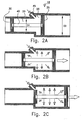
- Figs. 2A to 2C are a schematic illustration of a principle that is applied in the invention.
- Fig. 2A shows a volumetric system generally indicated as 18, which comprises two interconnected chambers 20 and 25 of unequal volume and of unequal diameters D1 and D2.
- Pistons 30 and 35 are displaceable within chambers 20 and 25, respectively, and are connected by rod 40 parallel to the longitudinal axis of system 18.
- the volume between the two pistons comprises two portions, each belonging to one of the two chambers. As the pistons move along the longitudinal axis of the system both portions vary. If a fluid is admitted to the system via inlet 45, a pressure is produced in each of said two chamber portions.
- piston 35 has a larger surface than piston 30, said pressure generates a resultant force (directed to the right as seen in the figures) on the assembly of the two pistons and rod 40, said assembly is displaced in said direction, and work can be obtained from said displacement. As more fluid is admitted through inlet 45, said assembly is additionally displaced, and more work may be obtained from volumetric system 18.
- Figs. 2B and 2C show successive stages of said process.
- FIG. 3 demonstrates the very basic concept of the present invention: a volumetric device consist of at least two volumetric units; transfer unit 60 and expansion unit 70 rotating about a common shaft 58. Said transfer unit 60 is charged through intake conduits 94 and 94A and then connected to said expansion unit via conduits 80 and 80A and combustors 75 and 75A. At the end of each expansion sector, the burnt mixture is discharged from expansion unit 70 through exhaust conduits 95 and 95A.
- Most of the forthcoming embodiments of the present invention are based on the above described device ( FIG 3 ) or alike with different, corresponding peripheral systems.
- an engine system 90 may be without a turbine, and the pressure of the fluid between transfer unit 60 and expansion unit 70 can be utilized for driving a load connected to shaft 58.
- Compressor 55 forces compressed working fluid into the system, whereby it is transferred to combustors 85 and 85A, heated in accordance with the present invention, and then discharged through exhaust ports 95 and 95A.
- Figs. 5 and 5A schematically illustrate a gas turbine engine system based on a volumetric (rotary lobe herein) positive displacement cycle in accordance with the present invention.
- the system is indicated generally as 50. It comprises a compressor 55, a (first) transfer volumetric device 60, a (second) volumetric device 70, which is an expansion volumetric device, and a turbine 80, all of which devices rotate about a common shaft 58.
- Fig. 5A the system is shown in schematic side view, while in Fig. 5 the said devices are shown in schematic cross-section as laterally displaced from one another while in fact they are aligned along a common longitudinal axis.
- Working fluid 59 after being compressed by compressor 55, flows through conduits 62 and 62A and is admitted to transfer volumetric device 60 via ports 64 and 64A, respectively.
- transfer volumetric device 60 is provided with three lobes 66. It will be appreciated that any number of lobes may be employed.
- an inlet chamber is defined between casing 63, lobe 66B and buffer 68A .
- maximum volume of the chamber is defined between casing 63 and lobes 66B and 66C.
- On continuation of clockwise rotation lobe 66B is passing buffer 68 and said chamber become an outlet chamber while it's volume is diminishing between lobe 66C and buffer 68 urging the fluid into combustor 85 through conduit 87. The same process is taking place at the other half of the same device.
- Each rotary valve demarcates a controlled volume of fluid through which work is obtainable in the engine system, and additionally urges said controlled volume to combustors 85 and 85A.
- rotary buffer 68A is engaged by lobe 66C.
- lobe 66A engages rotary buffer 68A.
- compressed working fluid is discharged in bursts to combustors 85 and 85A via conduits 87 and 87A respectively, and another charge of working fluid is concurrently admitted to the transfer unit 60.
- the combustors 85 and 85A comprise injectors 89 and 89A respectively. Fuel is injected into the compressed working fluid by means of injectors 89 and 89A, so that the resulting combustible mixture is ignited and burned in a steady state, thereby raising the pressure and temperature of the working fluid.
- the combustion gases constitute a heated working fluid. They are discharged to expansion volumetric device 70 via conduits 91 and 91A.
- Expansion volumetric device 70 is structured like transfer volumetric device 60 except for its scale. It comprises a rotor with three lobes; 75A, 75B and 75C and rotary buffers; 77 and 77A. In the condition shown in Fig 5 , an expansion chamber is defined between buffer 77A and lobe 75A and an outlet chamber is defined between lobe 75A and buffer 77 in one sector of 180° of the expansion unit. A second expansion chamber is defined between buffer 77 and lobe 75C and an outlet chamber is defined between lobe 75C and buffer 77A in the other sector of 180° of the expansion unit.
- the third lobe 75B is crossing the rotary buffer 77 through a matching dent in order to perform the same operation as lobe 75A and lobe 75C in a sequence.
- the volumetric device (transfer and expansion) is performing six complete cycles during each revolution of 360°.
- the volumetric device is performing twelve complete cycles during each revolution of 360°.
- a Wankel system volumetric device is performing six complete cycles of the rotors during each revolution of 360°, but the main shaft (which is directly connected to the compressor fan) is rotating three times faster.
- This pressure is conducted to turbine 80 via conduits 93 and 93A in order to use its kinetic energy in the turbine.
- FIG. 5B an engine configuration comprising two independent shafts is illustrated.
- Compressor 55 and volumetric devices 60 and 70 rotate about shaft 46, while turbine 80 rotates about shaft 47.
- turbine 80 rotates at a speed independent of the speed of expansion volumetric device 70, according to an external load connected to coupling 49.
- Shaft 47 may drive for example a transmission system (not shown).
- the exhaust from expansion unit 70 may be reheated by secondary combustors 96 and 96A before introduction to turbine 80 in order to increase the engine output.
- the burned combustion gases still contain a sufficient amount of oxygen to warrant the use of secondary combustors.
- one-way clutch 48 as illustrated in Fig. 5C may be used to further increase the flexibility of the engine configuration.
- turbine 80 When turbine 80 is under a heavy load at coupling 49 and the speed of shaft 47 is lowered to substantially that of shaft 46, one-way clutch 48 is engaged and the power performed by shaft 47 is added the power take of shaft 46.
- the speed of shaft 47 Upon reduction of the load connected to coupling 49, the speed of shaft 47 can increase to a value much higher than shaft 46 and one-way clutch 48 is disengaged from shaft 46, to allow the two shafts to rotate at different speeds.
- Fig. 5D schematically illustrates an engine system which differs from that illustrated in Fig. 5 only in that it comprises four, instead of two, buffered sectors in each volumetric device.
- Fig. 5D is therefore self-explanatory. It will be understood that different numbers of buffered sectors could be provided in such engine systems, and four sectors are known in Fig. 5D only by way of example.
- FIG. 6A and 6B Another preferred embodiment of the present invention comprising a turbocharged engine system generally indicated by 150 is illustrated in Figs. 6A and 6B .
- Intake air 159 is compressed in two stages, by compressor 155 coaxial with volumetric transfer unit 160 and expansion volumetric unit 170 and by turbocompressors 110 and 110A fed with compressed air from compressor 155 through conduits 162 and 162A, respectively.
- Turbocharged air flows through conduits 132 and 132A and is admitted to transfer unit 160 at entry ports 164 and 164A, respectively, with such an increased pressure that more fuel may be burned in combustors 185 and 185A, respectively, and that engine system 150 may generate more power at shaft 158.
- the exhaust from expansion unit 170 flows through conduits 193 and 193A and provides the motive force, by means of the kinetic energy of the combustion gases discharged from expansion unit 170 to rotate turbines 120 and 120A.
- Turbines 120 and 120A in turn drive turbocompressors 110 and 110A, respectively, and provide more power at the corresponding output shaft 125 and 125A, respectively.
- a system generally designated by 230 is illustrated in Fig. 7 , in which the positive displacement cycle is based on a Wankel mechanism, in which a triangular rotor rotates on an eccentric shaft inside an epitrochoidal housing. Intake air is compressed in two stages, namely by compressor 155, which is coaxial with volumetric transfer unit 210 and with expansion volumetric unit 240, which has a larger inner volume than that of the first volumetric transfer unit 210, and by turbocompressors 110 and 110A whose inlet is compressed air flowing from compressor 155 through conduits 162 and 162A, respectively.
- transfer unit 210 can deliver turbocharged air to the combustors and expansion unit 240 allows for the expansion of combustion gases so that a desired amount of work is obtainable at common shaft 158, in accordance with the present invention.
- FIG 8 Another volumetric system generally designated by 280 in accordance with the present invention is illustrated in FIG 8 , in which the positive displacement cycle is based on a reciprocating piston system.
- Fig 8 like with any other sort of adoptable volumetric mechanism of the present invention, a wide variety of embodiments with different peripheral systems in accordance. The following description of Fig 8 is just one of numbered feasibilities.
- Intake air is compressed in two stages, namely by compressor 155 coaxial with volumetric transfer unit 260 and expansion volumetric unit 290 and by turbocompressors 110 and 110A whose inlet is compressed air flowing from compressor 155 through conduits 162 and 162A, respectively.
- Each controlled volume of turbocharged working fluid is sequentially fed to the first transfer volumetric unit and is sequentially urged from the transfer unit 260 to the expansion volumetric unit 290 by a predetermined timing of valve sets.
- Fig 9 is an explanatory system which describes the adaptation feasibility of common systems of prior art by the present invented system in order to achieve higher performance and efficiency.
- An engine is generally indicated by 350, according to another preferred embodiment of the present invention illustrated in Fig 9 , showing the high adaptability of the present invention for common peripheral systems in order to improve efficiency and output that can be further increased by the employment of intercoolers, in order to cool the temperature of compressed working fluid and thereby to provide fluid at higher density to the volumetric devices.
- Axial compressor 310 forces ambient air 315 to first stage intercoolers 320 and 320A, after which the compressed and cooled air is additionally compressed at radial compressor 330 and second stage intercoolers 340 and 340A, respectively.
- a higher fluid density therefore results between expansion volumetric unit 370 and transfer volumetric unit 360.
- Heat exchangers 390 and 390A are using exhaust gases temperature to preheat the working fluid at entrance to the combustors in order to achieve higher efficiency and output.
- an engine of the present invention may be adapted for use with land motor vehicle of all sorts, which requires a wide variation output in load and rotational speed, with an immediate response to a change in one of the operational parameters of the system. Due to the unique configuration, an engine in accordance with the present invention is advantageously suitable for the burning of any existing engine fuel.
- engine 400 which is suitable for operation with motor vehicles is illustrated in Figs. 10A and 10B .
- Engine 400 comprises three stages of intercoolers: first stage intercoolers 420 and 420A for cooling compressed ambient air from axial compressor 410, second stage intercoolers 440 and 440A for cooling compressed air from radial compressor 430 which compresses the discharge from the first stage intercoolers, and third stage intercoolers 455 and 455A for cooling compressed air from turbocompressors 450 and 450A, respectively, which receive air from a corresponding second stage intercooler.
- the discharge from the third stage intercoolers is introduced to transfer unit 460.
- the discharge from transfer unit 460 is heated by heat exchangers 462 and 462A, which utilize the exhaust from turbocompressors 450 and 450A, respectively, as indicated by conduits 452 and 452A, respectively, before introduction into primary combustors 485 and 485A, respectively, so as to increase the available energy level of the working fluid.
- the fluid heated by the primary combustors flows to expansion unit 470 and performs work at main shaft 480.
- engine 400 is further increased by providing a third volumetric device 490, which rotates about an independent shaft 491 and transmits an additional amount of power.
- the exhaust from expansion unit 470 is heated by secondary combustors 475 and 475A, so as to function as a pressure generator for volumetric device 490 by utilizing the oxygen content of the unburned exhaust.
- the heated exhaust from expansion unit 470 is introduced to selector valves 495 and 495A.
- selector valve 495 for example, is actuatable to direct the flow of the expansion unit outlet into inlet port 496 resulting in clockwise rotation of shaft 491 or into outlet port 497 resulting in counterclockwise rotation of shaft 491.
- the exhaust from volumetric device 490 is then discharged by lines 498 and 498A, respectively, to the turbines of turbochargers 458 and 458A, respectively, which drive a corresponding turbocompressor. If so desired, the exhaust from volumetric device 490 may be directed to a heat exchanger, or to any other suitable application. Any of the hereinabove peripheral units as secondary combustors, intercoolers and heat exchanger can be in use or avoided according to any specific design.
- Volumetric device 490 develops power by means of any of the positive displacement cycles described hereinabove. Since independent shaft 491 is coupled to a load, volumetric device serves as a torque converter, wherein the torque applied by shaft 491 is variable, depending on the load and on the pressure between expansion unit 470 and volumetric device 490.
- the volume of device 490 is advantageously relatively small if shaft 491 is desired to be rotated at a relatively high velocity and low torque. Alternatively, the volume of device 490 is chosen to be larger if shaft 491 is desired to be rotated at a relatively low velocity and high torque.
- a locking mechanism is situated between main shaft 480 and secondary shaft 191 in order to enable unification of the two shafts into one for certain utilizations.
- Bypass valves 465 and 465A are functioning as engagement/ disengagement device, enabling to keep the engine running and idling while third volumetric unit (torque converter) is disengaged.
- Engine 400 is adapted to provide a flexible and gradual transmission by employing a plurality of volumetric devices, as illustrated in Fig. 10C , disposed at the outlet of secondary combustors 475 and 475A, with a number of selector valves in use to select through which combination of devices working fluid heated by secondary combustors will flow.
- Working fluid heated by secondary combustors flows in parallel conduits into a corresponding volumetric device, and a separate selector valve in communication with each conduit controls the flow through the corresponding conduit.
- Each of these volumetric devices are coaxial and the net power output from independent shaft 491 is the sum of the power output from each individual volumetric device.
- the engine produces a maximum amount of torque when the discharge from the secondary combustors is directed to all the volumetric devices in parallel. If an operator desires to smoothly lower the torque and increase the speed of shaft 491, one selector valve is actuated to prevent the flow to the corresponding individual volumetric device, the same amount of fluid is then flowing through one less device, causing augmentation of velocity on the account of torque diminution.
- any number of volumetric devices may be by passed in order to achieve a desired speed or torque.
- the direction of independent shaft 491 is changed by actuating the selector valve of each volumetric device in unison.
- the selector valves are automatically actuated upon input of an operator.
- Fig. 10D schematically illustrates an engine, comprising, in addition to volumetric devices 701 and 702, such as have been illustrated in preceding embodiments, three additional volumetric devices 708, 709 and 710 that serve as torque converters.
- Numeral 700 indicates the shaft to which volumetric devices 701 and 702 are keyed.
- 703 is a compressor
- 704 is a combustor
- 705 is a turbocharger.
- Said additional volumetric devices 708, 709 and 710 can be activated or disactivated by opening or closing valves 711, 712 and 713 respectively.
- volumetric devices 708, 709 and 710 are mounted on shaft 715, they may be mounted through one-way bearings 716, 717 and 718 respectively, so that if they are deactivated, they do not rotate with shaft 715.
- the said additional volumetric devices vary the torque and the speed of rotation of the engine in two ways: one, by activating appropriate combination of volumetric transmission devices in general accordance with load and speed and secondly by the variation of the pressure buildup in the said volumetric activated units based on the compressible nature of the fluid (usually air) in order to cope with load and speed variations within a chosen combination of transmission volumetric units.
- FIG. 11 Another preferred embodiment of the present invention is illustrated in Fig. 11 , for use as a turbofan engine generally designated as 550.
- Atmospheric air 510 is admitted to turbocompressors 520 and 520A under normal pressure produced by the fan 530, and is compressed furthermore before delivery to transfer unit 560.
- Transfer unit 560 discharges the compressed air to combustors 585 and 585A, from which combustion gases flow to expansion volumetric device 570.
- Fan 530 generates a crossfan streamline 515 which flows through duct 590 and results in thrust.
- the exhaust from device 570 is delivered to turbines 522 and 522A of the turbochargers, in order to drive a corresponding turbocompressor.
- the exhaust from turbines 522 and 522A is discharged to the atmosphere and provides additional thrust.
- Fig. 12 illustrates another preferred embodiment in which a turbojet engine system indicated generally by 650 comprises axial compressor 610, radial compressor 620, transfer volumetric device 660, engine combustors 685 and 685A, expansion volumetric device 670 and main combustor 690.
- the majority of the aircraft thrust is provided by main combustor 690.
- Compressed air from compressors 610 and 620 introduced to main combustor 690 via apertures 675 is mixed with fuel injected by injector 640, and the combustible mixture is burned to produce a powerful jet stream.
- Compressors 610 and 620 are driven by shaft 658, as a result of the torque imparted thereto by device 670.
- the remainder of the compressed air not admitted to main combustor690 is cooling the main combustor and its envelope and together with the exhaust from expansion unit 670 provide auxiliary thrust which streams to the rearward side of the engine, through outlet nozzle 695.
- an aircraft engine corresponding to the embodiment of Fig. 11 or Fig. 12 drives the compressors by means of energy, due to the pressure between the volumetric device, and therefore can operate at high efficiency despite a wide variation in speed and load. Consequently such aircraft engines are suitable for applications that heretofore have been unfeasible.
Landscapes
- Engineering & Computer Science (AREA)
- Mechanical Engineering (AREA)
- General Engineering & Computer Science (AREA)
- Chemical & Material Sciences (AREA)
- Combustion & Propulsion (AREA)
- Supercharger (AREA)
- Engine Equipment That Uses Special Cycles (AREA)
- Separation By Low-Temperature Treatments (AREA)
- Characterised By The Charging Evacuation (AREA)
- Valve Device For Special Equipments (AREA)
- Control Of Throttle Valves Provided In The Intake System Or In The Exhaust System (AREA)
- Control Of Motors That Do Not Use Commutators (AREA)
Abstract
Description
- The present invention relates to the field of thermal engine systems, particularly gas turbines. More particularly the invention relates to a gas turbine in which a controlled volume of fluid undergoes a continuous- flow positive displacement cycle.
- The vast majority of world-wide prime mover capacity is in the form of internal combustion engines. These include engines in automobiles, trucks, tractors, ships, airplanes, and stationary plants. Thermodynamically, engines are classified according to their basic cycle. With respect to reciprocating and other types of volumetric internal combustion engines.
- A volumetric internal combustion engine possesses an advantage over a conventional gas turbine engine in that it operates by means of static pressure within a closed volume which enables effective and efficient operation with low dependence on engine velocity and therefore relatively high efficiency and output through a wide range of engine velocity. Also its parts can generally work at temperatures much less than the maximum cyclic temperature. As a result, said maximum cyclic temperature may be high, thereby allowing for a high cyclic efficiency. Other advantages associated with the volumetric internal combustion engine include its relatively low cost, high mechanical efficiency and wide variation in speed and load. These advantages are of particular importance in the field of land transportation.
- A typical single-shaft open-type gas turbine engine designated by
numeral 10 is illustrated inFig. 1 .Gas turbine engine 10 comprisescompressor 2,combustor 5 andturbine 7, which is coupled to the compressor byshaft 8.Atmospheric air 3 enterscompressor 2, in which its pressure and temperature is increased. The compressed air is then forced intocombustor 5, in which it mixes and burns with a fuel. Hot pressurizedcombustion gases 9 expand withinturbine 7 and achieve a higher velocity, causingshaft 8 to rotate, thereby drivingcompressor 2 and any load connected to the shaft, due to the kinetic energy of the combustion gas stream.Combustion gases 9 are then discharged to the atmosphere. The net work of the cycle is the difference between the work obtainable in the expansion process and the work of compression. - Relative to a volumetric engine, a gas turbine engine has a greater power to weight ratio, and therefore its size is smaller than its volumetric engine counterpart at a given power output. A gas turbine engine is capable of rapid start-up and loading, and is likely to have a long life. Also, an open-type gas turbine engine offers the advantage of simple sealing systems. No effective cooling is possible.
- A gas turbine engine has good efficiency at full load when the operation temperature and kinetic energy of the combustion gases, compressor pressure ratio, and rotational velocity of the shaft are high. However, the efficiency is reduced when the load is lowered, such as by lowering the operation temperature or the rotational velocity of the shaft, Consequently, prior art gas turbine engines have been usually found to be suitable for those applications requiring substantially constant rotational velocity and output, such as transcontinental aircraft, or power plants, but heretofore have been found not to be suitable for uses such as land transportation or light aircraft which require wide variations in speed and load.
-
Fig. 8 ofDE 4241403 discloses a rotary engine that comprises a compression bank, a collecting chamber which receives compressed working fluid, a combustion chamber for the compressed working fluid, and an expansion bank. Each of these banks is provided with a set of two rotors and with a corresponding flap valve for controlling flow rate and direction. Since flap valves are employed, the working fluid is not necessarily transferred in each stage of the positive displacement cycle, depending on the operating conditions of the flow, and therefore the flow of working fluid is not continuous. Another deficiency of this engine is that a collection chamber is employed, resulting in lowered engine efficiency due to the increased parasitic volume of the engine. Also, two rotors are employed in each bank, adding cost and complexity to the engine. - It is an object of the present invention to provide a combustion engine system, particularly a gas turbine engine that allows for a wide variation in speed and load.
- It is an additional object of the present invention to provide a gas turbine engine that is suitable for use in land transportation.
- It is an additional advantage of the present invention to provide a combustion engine system that can efficiently burn a broad range of fuels.
- It is another object of the present invention to provide a combustion engine system that is cost effective.
- It is a further object of the present invention to provide a gas turbine engine that overcomes the disadvantages of the prior art devices while retaining their inherent advantages.
- It is a still further object of the present invention to combine the advantages of volumetric systems with those of flow systems.
- Other objects and advantages of the invention will become apparent as the description proceeds.
- The present invention provides an improved combustion engine system comprising at least a first and a second volumetric device, through which work is performed during continuous flow of a compressible fluid from said first to said second volumetric device.
- According to a preferred embodiment, the engine comprises an additional work producing device, particularly a turbine, driven by the fluid discharged from said second volumetric device.
- As referred to herein, a "fluid displacement cycle" is defined as a process by which a fluid is displaced in a succession of stages, which may be repeated as many times as desired, theoretically for an unlimited number of times. If the displacement of the fluid in each stage is determined by the displacement or displacements of a mechanical element or a number of such elements from a first to a second position, the cycle is called a "positive displacement cycle".
- As referred to herein, a "volumetric device" is a device that delivers the same volume of fluid that it receives. Generally, such a device uses a positive displacement cycle to transfer the same amount of fluid at each cycle. It should be understood that this need not be and generally is not the sole function of a volumetric device, but rather one of its functions. Typically, the same volume of fluid is received and delivered by the device in each stage. Said volume of fluid will be called hereinafter "controlled volume".
- The transfer of a fluid from a first volumetric device to a second volumetric device, wherein fluid is transferred during each stage of the positive displacement cycle of the volumetric devices, is considered herein to be and is called "continuous flow".
- A "turbine" is defined herein as a device for outputting work or for turbocharging fluid by transferring kinetic energy of a driving fluid into mechanical energy upon passage thereof across turbine blades. In embodiments of this invention comprising turbines, the driving fluid is the exhaust of the second of two volumetric devices.
- In one preferred embodiment, the present invention provides an engine system which comprises:
- a) a first volumetric device;
- b) means for feeding a compressible fluid to said first volumetric transfer unit;
- c) a heat source or sources;
- d) means for driving said first volumetric transfer unit for sequentially transferring controlled volumes of said fluid to said heat source by positive displacement cycles;
- e) a second volumetric device, larger then the first one, for receiving heated controlled volumes of said fluid from said heat source;
- f) means for driving said second volumetric device for sequentially discharging said heated controlled volumes of said fluid by positive displacement cycles; and
- g) means for synchronizing said means for driving said first and second volumetric device.
- In preferred embodiments:
- I) the means for synchronizing said means for driving said first and second volumetric device comprise a common shaft supporting said first and second volumetric devices for rotation.
- II) the means for feeding a compressible fluid to a first volumetric transfer unit include means for increasing the pressure of said fluid, preferably a compressor;
- III) the engine system further comprises a turbine and the discharge of said second volumetric device is the inlet of said turbine;
- IV) the heat sources are combustors fed with a fuel, which receive controlled volumes of fluid and cause said fuel to burn, thereby heating said fluid, wherein said fuel may but need not be any fossil-based engine fuel;
- V) the compressor, if any, the first and second volumetric device, and the turbine, if any, are keyed to the same main shaft;
- VI) the compressible fluid is usually air;
- VII) the engine system further comprises an additional work producing device, which is preferably but not necessarily a turbine, which device is driven by the fluid discharged from said second volumetric device and produces work from the kinetic energy of said discharged fluid.
- Since said first volumetric device transfers fluid to said second volumetric device, it may be called "transfer volumetric device". Since said second volumetric device receives heated controlled volumes of fluid from the heat source or sources, it may be called "expansion volumetric device". A torque is exerted on said common shaft means or said main shaft of said engine system, due to a static pressure between said transfer and said expansion volumetric device chambers, independent on the torque exerted by the gas turbine or other additional work producing device, if any.
- "Energy" denotes herein the net work done by the compressible fluid within the engine system while flowing to the discharge of said second volumetric device.
- The positive displacement cycle is effected by means of apparatus selected from the group of rotors provided with lobes, Wankel mechanism, reciprocating piston systems, or any other common or specially designed volumetric system.
- In a particular embodiment of the invention, the engine system further comprises at least one stage of intercoolers.
- In another embodiment, the engine system comprises two independent shafts to one of which is coupled a load, and preferably a one-way clutch for engaging and disengaging the two independent shafts, depending on a magnitude of the load.
- The engine system of the present invention is suitable for operation at a variable load and speed. Therefore the engine systems may be incorporated into a motor vehicle propulsion system. In one embodiment, the motor vehicle propulsion system comprises a secondary heater for heating exhaust from the second volumetric device and further comprises a third volumetric device rotating about an independent shaft, wherein the discharge from the secondary heater is the working fluid of said third volumetric device, said third volumetric device being adapted to be a speed and torque converter in response to a variable load coupled to said independent shaft, the engine system further comprising a rotational direction controller of said independent shaft by a valve means which directs said discharge from the secondary heater alternatively between the inlet and outlet ports of said third volumetric device. If necessary, a bypass valve that serves as engage and disengage device between the motor assembly and torque converter assembly is installed so that torque converter can be repressed while the motor is operating.
- The motor vehicle propulsion system may further comprise a first stage intercooler for cooling the discharge flowing from a first compressor to a second compressor and a second stage intercooler for cooling the discharge flowing from the second compressor to the turbocompressors of the turbochargers. It may further comprise a third stage intercooler for cooling the discharge flowing from the turbocompressor of the turbocharger to the first volumetric device, and a heat exchanger for heating the fluid flowing from the first volumetric device to the heat source by means of the discharge from the turbine of the turbocharger.
- The motor vehicle propulsion system preferably further comprises a transmission comprising:
- a) a plurality of coaxial volumetric devices rotatable about the independent shaft;
- b) a plurality of conduits through which the discharge from the secondary heater flows in parallel to each of said plurality of volumetric devices, respectively;
- c) a plurality of selector valves provided with each of said plurality of volumetric devices, respectively, for changing the directional direction of the independent shaft by directing the flow through a corresponding conduit alternatively between the inlet port and outlet port of the corresponding volumetric device upon actuation of each of said selector valves in unison; and
- d) a plurality of bypass valves in communication with each of said conduits, respectively, for selecting through which combination of said plurality of volumetric devices discharge from the secondary heater will flow,
- Preferably the plurality of selector valves are automatically actuated upon input of an operator or speed and torque controller.
- In another preferred embodiment, the engine system is a turbofan engine system which further comprises a turbocompressor for compressing atmospheric air and delivering said compressed air to a transfer volumetric device and a turbine driven by discharge from an expansion volumetric device for driving said turbocompressor, wherein the main shaft drives a fan which generates a crossfan streamline and a main thrust for an aircraft, exhaust from said turbine being discharged to the atmosphere and providing auxiliary thrust which is in addition to said main thrust. Alike embodiment can be realized without a turbocompressor by using the fan thrust also for the feeding of the volumetric device.
- In another preferred embodiment of the present invention, the engine system is a turbojet engine system, wherein the expansion volumetric device provides auxiliary thrust which is in addition to the main thrust for an aircraft provided by a jet stream generated by a main burner, an air stream from said at least one compressor feeding the inlet volumetric chamber and the main burner. Alike embodiment can use turbo compressor(s) in order to improve efficiency and output.
- In the drawings:
-
Fig. 1 is a schematic drawing of a prior art gas turbine system; -
Fig. 2 is a schematic drawing of a volumetric system comprised of two unequally sized chambers; -
Fig. 3 is a flow diagram of an engine system which does not drive a compressor or a turbine; -
Fig. 4 is a flow diagram of an engine system which does not drive a turbine; -
Fig. 5 is a flow diagram of an engine system according to the present invention;Fig. 5A is a schematic drawing of the system ofFig. 5 ;Fig. 5B is a schematic drawing of a similar engine system with the addition of secondary burners and a secondary shaft;Fig. 5C illustrates the addition of a one-way clutch; andFig. 5D demonstrates the capacity of constructing a volumetric system like that ofFig. 5 and other embodiments of the invented system, with multiple buffered sectors (four inFig. 5D ) in accordance with any specific design; -
Figs. 6A and 6B are schematic and flow diagrams, respectively, of an engine system which incorporates a turbocharger, showing the operation of a rotary lobe positive displacement cycle; -
Fig. 7 is a flow diagram of an engine system which incorporates a turbocharger, showing the operation of a Wankel-based positive displacement system; -
Fig. 8 is a flow diagram of an engine system which incorporates a turbocharger, showing the operation of a reciprocating piston positive displacement system; -
Fig. 9 is a flow diagram of an engine system which incorporates intercoolers and heat exchangers; -
Figs. 10A and10B are flow and schematic diagrams, respectively, of an engine system suitable for motor vehicles, whileFig. 10C illustrates the operation of a selector valve and declutching (bypass) valve; -
Fig. 10D is a schematic drawing of a motor vehicle transmission system (torque converter) comprising a plurality of coaxial volumetric devices rotatable about an independent shaft and their control system; -
Fig. 11 is a schematic drawing of an engine system suitable for a turbofan, and -
Fig. 12 is a schematic drawing of an engine system suitable for a turbojet. - In one embodiment thereof, the present invention provides a novel gas turbine engine system in which the working fluid imparts a torque upstream to the turbine blades, so that a wide variation in load and shaft speed may be realized without a significant reduction in cyclical efficiency. Prior art gas turbine engines achieve a relatively high cyclical efficiency at full load when the kinetic energy of combustion gases flowing from a combustor to a turbine is at a maximum; however, their efficiency is significantly lowered following a reduction in kinetic energy of the combustion gases and a concomitant reduction in shaft speed. Use of prior art gas turbine engines is therefore precluded for those applications which require a wide variation in speed and load, such as land transportation or light aircraft. In contrast, the engine system of the present invention incorporates a positive displacement cycle by which a transfer volumetric device and an expansion volumetric device in fluid communication with one another by means of conduits and a combustor. A torque, exerted on the main engine shaft, is generated due to difference in size (and volume) between the two volumes and rotors under the same pressure. The energy of the working fluid is therefore utilized for various applications, as will be described hereinafter, which increases the cyclical efficiency of the engine system as well as its flexibility in terms of performing work during changes of speed and load.
-
Figs. 2A to 2C are a schematic illustration of a principle that is applied in the invention.Fig. 2A shows a volumetric system generally indicated as 18, which comprises twointerconnected chambers Pistons chambers rod 40 parallel to the longitudinal axis ofsystem 18. The volume between the two pistons comprises two portions, each belonging to one of the two chambers. As the pistons move along the longitudinal axis of the system both portions vary. If a fluid is admitted to the system viainlet 45, a pressure is produced in each of said two chamber portions. Sincepiston 35 has a larger surface thanpiston 30, said pressure generates a resultant force (directed to the right as seen in the figures) on the assembly of the two pistons androd 40, said assembly is displaced in said direction, and work can be obtained from said displacement. As more fluid is admitted throughinlet 45, said assembly is additionally displaced, and more work may be obtained fromvolumetric system 18.Figs. 2B and 2C show successive stages of said process. - All of the following embodiments are described as comprising two independent flow paths of working fluid. It will be understood that any number of flow paths may be employed with similar results, and two flow paths have been chosen to simplify the description.
-
FIG. 3 demonstrates the very basic concept of the present invention: a volumetric device consist of at least two volumetric units;transfer unit 60 andexpansion unit 70 rotating about acommon shaft 58. Saidtransfer unit 60 is charged throughintake conduits conduits combustors expansion unit 70 throughexhaust conduits FIG 3 ) or alike with different, corresponding peripheral systems. - As shown in
Fig. 4 , anengine system 90 may be without a turbine, and the pressure of the fluid betweentransfer unit 60 andexpansion unit 70 can be utilized for driving a load connected toshaft 58.Compressor 55 forces compressed working fluid into the system, whereby it is transferred to combustors 85 and 85A, heated in accordance with the present invention, and then discharged throughexhaust ports -
Figs. 5 and5A schematically illustrate a gas turbine engine system based on a volumetric (rotary lobe herein) positive displacement cycle in accordance with the present invention. The system is indicated generally as 50. It comprises acompressor 55, a (first) transfervolumetric device 60, a (second)volumetric device 70, which is an expansion volumetric device, and aturbine 80, all of which devices rotate about acommon shaft 58. InFig. 5A the system is shown in schematic side view, while inFig. 5 the said devices are shown in schematic cross-section as laterally displaced from one another while in fact they are aligned along a common longitudinal axis. Workingfluid 59, after being compressed bycompressor 55, flows throughconduits volumetric device 60 viaports - In this embodiment transfer
volumetric device 60 is provided with three lobes 66. It will be appreciated that any number of lobes may be employed. In the position of said device shown inFig. 5 , an inlet chamber is defined between casing 63,lobe 66B andbuffer 68A . Duringrotation lobe 66C is passingbuffer 68A and then maximum volume of the chamber is defined between casing 63 andlobes clockwise rotation lobe 66B is passingbuffer 68 and said chamber become an outlet chamber while it's volume is diminishing betweenlobe 66C and buffer 68 urging the fluid intocombustor 85 throughconduit 87. The same process is taking place at the other half of the same device. The different in lobe area (and as a result, in volume) between the expansion volumetric device and the transfer volumetric device, when under pressure generates moment aboutshaft 58 causing it to rotate (clockwise). As said shaft rotates, said inlet chambers are increased and said outlet chambers are reduced. The content of said outlet chambers is fed to combustors 85 and 85A. Said content has the volume that is referred herein as the "controlled volume". Concurrently and gradually through a rotation ofshaft 58 by 180° (generally, a number of degrees equal to 360 divided by the number of buffers), in accordance with the description hereinabove, it is understood that every lobe that is passing through a buffer is forming a new inlet chamber behind it and defining an outlet chamber ahead of it. - Whenever an inlet chamber is connected by a feed conduit to the compressor and an outlet chamber is concurrently connected by a discharge conduit to a combustor, communication between the feed conduit and the discharge conduit must be prevented. This is obtained by providing
rotary buffers conduits conduits volumetric transfer unit 60, demarcates a controlled volume of fluid through which work is obtainable in the engine system, and additionally urges said controlled volume to combustors 85 and 85A. In the condition shown inFig. 5 ,rotary buffer 68A is engaged bylobe 66C. Asdevice 60 continues to rotate in a clockwise direction,lobe 66A engagesrotary buffer 68A. During this stage, compressed working fluid is discharged in bursts to combustors 85 and 85A viaconduits transfer unit 60. - The
combustors injectors injectors volumetric device 70 viaconduits 91 and 91A. - Expansion
volumetric device 70 is structured like transfervolumetric device 60 except for its scale. It comprises a rotor with three lobes; 75A, 75B and 75C and rotary buffers; 77 and 77A. In the condition shown inFig 5 , an expansion chamber is defined betweenbuffer 77A andlobe 75A and an outlet chamber is defined betweenlobe 75A andbuffer 77 in one sector of 180° of the expansion unit. A second expansion chamber is defined betweenbuffer 77 andlobe 75C and an outlet chamber is defined betweenlobe 75C andbuffer 77A in the other sector of 180° of the expansion unit. Thethird lobe 75B is crossing therotary buffer 77 through a matching dent in order to perform the same operation aslobe 75A andlobe 75C in a sequence. In the structure shown inFigs. 3 ,4 ,6B and5 the volumetric device (transfer and expansion) is performing six complete cycles during each revolution of 360°. In the structure shown inFig. 5D the volumetric device is performing twelve complete cycles during each revolution of 360°. InFig. 7 , a Wankel system volumetric device is performing six complete cycles of the rotors during each revolution of 360°, but the main shaft (which is directly connected to the compressor fan) is rotating three times faster. - Since the pressure during the expansion cycle build up continually, the remaining pressure at the end of each expansion sector is relatively high.
- This pressure is conducted to
turbine 80 viaconduits - In
Fig. 5B an engine configuration comprising two independent shafts is illustrated.Compressor 55 andvolumetric devices shaft 46, whileturbine 80 rotates aboutshaft 47. As aresult turbine 80 rotates at a speed independent of the speed of expansionvolumetric device 70, according to an external load connected tocoupling 49.Shaft 47 may drive for example a transmission system (not shown). Optionally, the exhaust fromexpansion unit 70 may be reheated bysecondary combustors turbine 80 in order to increase the engine output. After expansion within expansionvolumetric device 70, the burned combustion gases still contain a sufficient amount of oxygen to warrant the use of secondary combustors. - If so desired, one-way clutch 48 as illustrated in
Fig. 5C may be used to further increase the flexibility of the engine configuration. Whenturbine 80 is under a heavy load atcoupling 49 and the speed ofshaft 47 is lowered to substantially that ofshaft 46, one-way clutch 48 is engaged and the power performed byshaft 47 is added the power take ofshaft 46. Upon reduction of the load connected tocoupling 49, the speed ofshaft 47 can increase to a value much higher thanshaft 46 and one-way clutch 48 is disengaged fromshaft 46, to allow the two shafts to rotate at different speeds. -
Fig. 5D schematically illustrates an engine system which differs from that illustrated inFig. 5 only in that it comprises four, instead of two, buffered sectors in each volumetric device.Fig. 5D is therefore self-explanatory. It will be understood that different numbers of buffered sectors could be provided in such engine systems, and four sectors are known inFig. 5D only by way of example. - Another preferred embodiment of the present invention comprising a turbocharged engine system generally indicated by 150 is illustrated in
Figs. 6A and 6B .Intake air 159 is compressed in two stages, bycompressor 155 coaxial withvolumetric transfer unit 160 and expansionvolumetric unit 170 and byturbocompressors compressor 155 throughconduits conduits unit 160 atentry ports combustors engine system 150 may generate more power atshaft 158. The exhaust fromexpansion unit 170 flows throughconduits expansion unit 170 to rotateturbines Turbines - The present invention may be performed by means of other positive displacement devices. A system generally designated by 230 is illustrated in
Fig. 7 , in which the positive displacement cycle is based on a Wankel mechanism, in which a triangular rotor rotates on an eccentric shaft inside an epitrochoidal housing. Intake air is compressed in two stages, namely bycompressor 155, which is coaxial withvolumetric transfer unit 210 and with expansionvolumetric unit 240, which has a larger inner volume than that of the firstvolumetric transfer unit 210, and byturbocompressors compressor 155 throughconduits unit 210 can deliver turbocharged air to the combustors andexpansion unit 240 allows for the expansion of combustion gases so that a desired amount of work is obtainable atcommon shaft 158, in accordance with the present invention. - Another volumetric system generally designated by 280 in accordance with the present invention is illustrated in
FIG 8 , in which the positive displacement cycle is based on a reciprocating piston system. InFig 8 , like with any other sort of adoptable volumetric mechanism of the present invention, a wide variety of embodiments with different peripheral systems in accordance. The following description ofFig 8 is just one of numbered feasibilities. - Intake air is compressed in two stages, namely by
compressor 155 coaxial withvolumetric transfer unit 260 and expansionvolumetric unit 290 and byturbocompressors compressor 155 throughconduits transfer unit 260 to the expansionvolumetric unit 290 by a predetermined timing of valve sets.Fig 9 is an explanatory system which describes the adaptation feasibility of common systems of prior art by the present invented system in order to achieve higher performance and efficiency. An engine is generally indicated by 350, according to another preferred embodiment of the present invention illustrated inFig 9 , showing the high adaptability of the present invention for common peripheral systems in order to improve efficiency and output that can be further increased by the employment of intercoolers, in order to cool the temperature of compressed working fluid and thereby to provide fluid at higher density to the volumetric devices.Axial compressor 310 forcesambient air 315 tofirst stage intercoolers radial compressor 330 andsecond stage intercoolers volumetric unit 370 and transfervolumetric unit 360.Heat exchangers - With implementation of the various applications described hereinabove, an engine of the present invention may be adapted for use with land motor vehicle of all sorts, which requires a wide variation output in load and rotational speed, with an immediate response to a change in one of the operational parameters of the system. Due to the unique configuration, an engine in accordance with the present invention is advantageously suitable for the burning of any existing engine fuel.
- In one preferred embodiment of the invention,
engine 400 which is suitable for operation with motor vehicles is illustrated inFigs. 10A and10B .Engine 400 comprises three stages of intercoolers:first stage intercoolers axial compressor 410,second stage intercoolers third stage intercoolers turbocompressors unit 460. The discharge fromtransfer unit 460 is heated byheat exchangers turbocompressors conduits primary combustors expansion unit 470 and performs work atmain shaft 480. - The flexibility and efficiency of
engine 400 is further increased by providing a thirdvolumetric device 490, which rotates about anindependent shaft 491 and transmits an additional amount of power. The exhaust fromexpansion unit 470 is heated bysecondary combustors volumetric device 490 by utilizing the oxygen content of the unburned exhaust. The heated exhaust fromexpansion unit 470 is introduced toselector valves Fig. 10C ,selector valve 495, for example, is actuatable to direct the flow of the expansion unit outlet intoinlet port 496 resulting in clockwise rotation ofshaft 491 or intooutlet port 497 resulting in counterclockwise rotation ofshaft 491. The exhaust fromvolumetric device 490 is then discharged bylines turbochargers volumetric device 490 may be directed to a heat exchanger, or to any other suitable application. Any of the hereinabove peripheral units as secondary combustors, intercoolers and heat exchanger can be in use or avoided according to any specific design. -
Volumetric device 490 develops power by means of any of the positive displacement cycles described hereinabove. Sinceindependent shaft 491 is coupled to a load, volumetric device serves as a torque converter, wherein the torque applied byshaft 491 is variable, depending on the load and on the pressure betweenexpansion unit 470 andvolumetric device 490. The volume ofdevice 490 is advantageously relatively small ifshaft 491 is desired to be rotated at a relatively high velocity and low torque. Alternatively, the volume ofdevice 490 is chosen to be larger ifshaft 491 is desired to be rotated at a relatively low velocity and high torque. A locking mechanism is situated betweenmain shaft 480 and secondary shaft 191 in order to enable unification of the two shafts into one for certain utilizations. Bypassvalves -
Engine 400 is adapted to provide a flexible and gradual transmission by employing a plurality of volumetric devices, as illustrated inFig. 10C , disposed at the outlet ofsecondary combustors independent shaft 491 is the sum of the power output from each individual volumetric device. Accordingly, the engine produces a maximum amount of torque when the discharge from the secondary combustors is directed to all the volumetric devices in parallel. If an operator desires to smoothly lower the torque and increase the speed ofshaft 491, one selector valve is actuated to prevent the flow to the corresponding individual volumetric device, the same amount of fluid is then flowing through one less device, causing augmentation of velocity on the account of torque diminution. - Similarly any number of volumetric devices may be by passed in order to achieve a desired speed or torque. The direction of
independent shaft 491 is changed by actuating the selector valve of each volumetric device in unison. Preferably the selector valves are automatically actuated upon input of an operator. -
Fig. 10D schematically illustrates an engine, comprising, in addition tovolumetric devices volumetric devices Numeral 700 indicates the shaft to whichvolumetric devices volumetric devices valves volumetric devices shaft 715, they may be mounted through one-way bearings shaft 715. The said additional volumetric devices vary the torque and the speed of rotation of the engine in two ways: one, by activating appropriate combination of volumetric transmission devices in general accordance with load and speed and secondly by the variation of the pressure buildup in the said volumetric activated units based on the compressible nature of the fluid (usually air) in order to cope with load and speed variations within a chosen combination of transmission volumetric units. - Another preferred embodiment of the present invention is illustrated in
Fig. 11 , for use as a turbofan engine generally designated as 550.Atmospheric air 510 is admitted toturbocompressors fan 530, and is compressed furthermore before delivery to transfer unit 560. Transfer unit 560 discharges the compressed air to combustors 585 and 585A, from which combustion gases flow to expansionvolumetric device 570. As the combustion gases expand, a motive force is produced due to the pressure between expansionvolumetric device 570 and transfer volumetric device 560, causing shaft 558 to rotate and to drivefan 530.Fan 530 generates acrossfan streamline 515 which flows throughduct 590 and results in thrust. The exhaust fromdevice 570 is delivered toturbines turbines -
Fig. 12 illustrates another preferred embodiment in which a turbojet engine system indicated generally by 650 comprisesaxial compressor 610,radial compressor 620, transfervolumetric device 660,engine combustors volumetric device 670 andmain combustor 690. The majority of the aircraft thrust is provided bymain combustor 690. Compressed air fromcompressors main combustor 690 via apertures 675 is mixed with fuel injected byinjector 640, and the combustible mixture is burned to produce a powerful jet stream.Compressors device 670. The remainder of the compressed air not admitted to main combustor690 is cooling the main combustor and its envelope and together with the exhaust fromexpansion unit 670 provide auxiliary thrust which streams to the rearward side of the engine, throughoutlet nozzle 695. - It will be appreciated that an aircraft engine corresponding to the embodiment of
Fig. 11 orFig. 12 drives the compressors by means of energy, due to the pressure between the volumetric device, and therefore can operate at high efficiency despite a wide variation in speed and load. Consequently such aircraft engines are suitable for applications that heretofore have been unfeasible. - To mass produce engines according to the present invention in a cost effective manner, one may produce the engines of the present invention in a modular fashion.
Claims (14)
- Engine system, comprising:a) a first volumetric device (60);b) one or more second volumetric devices (70) larger in volume than said first volumetric device;c) means for feeding a compressible fluid to said first volumetric device;d) a heat source (75) disposed between said first volumetric device and each of said second volumetric devices;e) means for driving said first volumetric device;f) means for driving each of said second volumetric devices such that each of said second volumetric devices receives heated controlled volumes of said fluid from said heat source by positive displacement cycles; andg) means for synchronizing (58) said means for driving said first and second volumetric devices,
characterized in that said engine system further comprisesh) one or more separate flow paths (94, 80, 95; 94A, 80A, 95A) for said fluid, each flow path beginning with a separate intake conduit (94, 94A) leading to said first volumetric device and ending with a separate discharge conduit (95,95A) coming from the outlet of a second volumetric device, each separate flow path being provided with a corresponding heat source (75, 75A) disposed between said first volumetric device and a second volumetric device,wherein said first volumetric device sequentially transfers controlled volumes of said fluid to the corresponding heat source by positive displacement cycles,
wherein each of said corresponding second volumetric devices sequentially receives heated controlled volumes of said fluid from the corresponding heat source via the corresponding separate flow path and sequentially discharges said heated controlled volumes of said fluid,
wherein work is performed during continuous flow of said compressible fluid from said first volumetric device to each of said second volumetric devices. - Engine system according to claim 1, further comprising an additional work producing device selected from the group of a turbine (120, 458) driven by the fluid discharged from the second volumetric device (170) or from a third volumetric device (490), a compressor (155) for feeding a compressible fluid to the first volumetric device (160), a turbine (80) keyed to a main shaft (58), at least one turbocompressor (110, 110A), a secondary combustor (96), at least one stage of intercoolers (320, 340), a second compressor (430) and a first stage intercooler (420, 420A) for cooling the discharge flowing from a first compressor (410) to a second compressor, a turbocompressor (450, 450A) and a second stage intercooler (440, 440A) for cooling the discharge flowing from said second compressor (430) to said turbocompressor, and a combination thereof.
- Engine system according to claim 1, wherein the means for synchronizing the means for driving the first (60) and second volumetric devices (70) comprise a common shaft (58) to which the first and second volumetric devices are keyed or independent shafts (480, 491) supporting said first (470) and second volumetric devices (490) for rotation.
- Engine system according to claim 1, wherein each heat source (75, 75A) is a combustor fed with a fuel, which receives controlled volumes of fluid and causes said fuel to burn, thereby heating and expanding said fluid.
- Engine system according to claim 2, wherein the compressor (155) is keyed to the main shaft (158).
- Engine system according to claim 1, wherein the positive displacement cycle is effected by means of apparatus selected from the group consisting of rotors (60) provided with lobes (66), Wankel mechanism (210), reciprocating piston systems (260), or any common or specially designed volumetric mechanism.
- Engine system according to claim 1, comprising two independent shafts (46, 47) to one of which are keyed the volumetric devices (60, 70), a load being coupled to the other shaft, and optionally further comprising a clutch (48) for engaging and disengaging two independent shafts, depending on a magnitude of the load.
- Propulsion system comprising an engine system (400) according to claim 1 and further comprising a third volumetric device (490) rotating about an independent shaft (491), wherein the discharge from a second volumetric device (470) is the working fluid of said third volumetric device, said third volumetric device being adapted to be a torque converter in response to a variable load coupled to said independent shaft, said propulsion system further comprising a rotational direction controller (495) of said independent shaft by a valve means which directs said discharge from a second volumetric device alternatively to an inlet port (496) and an outlet port (497) of said third volumetric device.
- Propulsion system according to claim 8, further comprising a transmission comprising:a) a plurality of coaxial third volumetric devices (708, 709, 710) rotatable about the independent shaft (715);b) a plurality of conduits through which the discharge from a second volumetric device flows in parallel to each of said plurality of third volumetric devices, respectively;c) a plurality of selector valves (711, 712, 713) in communication with each of said conduits, respectively, for selecting through which combination of said plurality of volumetric devices discharge from a second volumetric device will flow,wherein said propulsion system produces a maximum amount of torque when the discharge from a second volumetric device is directed to all of said plurality of volumetric devices in parallel, a lowered level of torque upon deactivation of at least one of said volumetric devices, and an increased level of torque upon activation of at least an additional one of said volumetric devices,
wherein said propulsion system develops a speed inversely proportional to the produced level of torque. - Propulsion system according to claim 8, further comprising a bypass valve (465) to serve as an engagement and disengagement device between an engine assembly and a torque converter assembly (490), for repressing the torque converter while the engine is in operation.
- Propulsion system according to any of claims 8 to 10, further comprising a secondary combustor (475) for heating the discharge from a second volumetric device (470), wherein the discharge from said secondary combustor is the working fluid of said third volumetric device (490).
- Propulsion system according to claim 11, wherein the discharge from the secondary combustor (475) flows in parallel to each of the plurality of volumetric devices (708, 709, 710), respectively, the plurality of selector valves selects through which combination of the plurality of volumetric devices discharge from the secondary combustor will flow, and a maximum amount of torque is produced when the discharge from the secondary combustor is directed to all of the plurality of volumetric devices in parallel, wherein said propulsion system develops a speed inversely proportional to the produced level of torque.
- Turbofan engine system (550) comprising an engine system according to claim 2, wherein the compressor is a turbocompressor (520, 520A) driven by discharge from an expansion volumetric device (570), and a fan (530) driven by said engine system, said fan generating a crossfan streamline (515) and a main thrust for an aircraft, exhaust from said turbocompressor being discharged to the atmosphere and providing auxiliary thrust in addition to said main thrust.
- Turbojet engine system (650), comprising an engine system according to claim 1 or 2 and further comprising a main combustor (690) for generating a gas stream and providing a main thrust for an aircraft and at least one compressor (610, 620) for introducing air into said main combustor, exhaust from said engine system being discharged to the atmosphere and providing auxiliary thrust in addition to said main thrust, wherein air compressed by said at least one compressor which is not introduced into said main combustor cools said main combustor and provides additional auxiliary thrust.
Applications Claiming Priority (3)
| Application Number | Priority Date | Filing Date | Title |
|---|---|---|---|
| US36384202P | 2002-03-14 | 2002-03-14 | |
| US363842P | 2002-03-14 | ||
| PCT/IL2003/000192 WO2003076779A1 (en) | 2002-03-14 | 2003-03-10 | Gas turbine engine system |
Publications (2)
| Publication Number | Publication Date |
|---|---|
| EP1490587A1 EP1490587A1 (en) | 2004-12-29 |
| EP1490587B1 true EP1490587B1 (en) | 2008-10-15 |
Family
ID=27805290
Family Applications (1)
| Application Number | Title | Priority Date | Filing Date |
|---|---|---|---|
| EP03710179A Expired - Lifetime EP1490587B1 (en) | 2002-03-14 | 2003-03-10 | Engine system |
Country Status (9)
| Country | Link |
|---|---|
| US (1) | US8109074B2 (en) |
| EP (1) | EP1490587B1 (en) |
| JP (1) | JP4541707B2 (en) |
| AT (1) | ATE411455T1 (en) |
| AU (1) | AU2003214599C1 (en) |
| CA (1) | CA2479235C (en) |
| DE (1) | DE60324119D1 (en) |
| IL (1) | IL164057A0 (en) |
| WO (1) | WO2003076779A1 (en) |
Families Citing this family (27)
| Publication number | Priority date | Publication date | Assignee | Title |
|---|---|---|---|---|
| EP1490587B1 (en) | 2002-03-14 | 2008-10-15 | Newton Propulsion Technologies Ltd. | Engine system |
| WO2004074655A1 (en) * | 2003-02-24 | 2004-09-02 | Pratt & Whitney Canada Corp. | Low volumetric compression ratio integrated turbo-compound rotary engine |
| IL157666A0 (en) * | 2003-08-31 | 2009-02-11 | Newton Propulsion Technologies Ltd | Novel gas turbine engine system |
| RO120985B1 (en) * | 2004-10-04 | 2006-10-30 | Petrica Lucian Georgescu | Rotary heat engine |
| JP4617822B2 (en) * | 2004-10-21 | 2011-01-26 | ダイキン工業株式会社 | Rotary expander |
| DE202005004902U1 (en) * | 2005-03-29 | 2005-05-25 | Mädge, Claus-Peter, Dipl.-Ing. | Internal combustion engine, in particular for vehicles such as motor vehicles |
| US8555611B2 (en) * | 2007-12-27 | 2013-10-15 | Arthur Vanmoor | Combustion engine with feedback gear/rotary pump input |
| US8235150B2 (en) * | 2008-06-24 | 2012-08-07 | Rez Mustafa | Pneumatic hybrid turbo transmission |
| WO2009158184A1 (en) * | 2008-06-24 | 2009-12-30 | Mustafa Rez | Pneumatic hybrid turbo-transmission |
| US8336304B2 (en) * | 2008-06-24 | 2012-12-25 | Rez Mustafa | Hydraulic hybrid turbo-transmission |
| DE102010004128A1 (en) * | 2009-12-02 | 2011-06-09 | Lang, Dieter, Dipl.-Ing. (FH) | Universal rotary compressor |
| US9467021B2 (en) * | 2010-02-16 | 2016-10-11 | Sine Waves, Inc. | Engine and induction generator |
| US20110241351A1 (en) * | 2010-04-06 | 2011-10-06 | Dale Euga | Power generating system employing a radial air cooled aircraft engine |
| WO2012057838A2 (en) * | 2010-10-27 | 2012-05-03 | Jesus Vazquez | Rotary valve continuous flow expansible chamber dynamic and positive displacement rotary devices |
| CN102200051B (en) * | 2011-04-05 | 2013-09-18 | 罗显平 | Connection method and device of compressed-air vehicle engine |
| JP5218929B1 (en) * | 2012-09-11 | 2013-06-26 | 武史 畑中 | Rotary combustion engine, hybrid rotary combustion engine, and machine equipped with these |
| US10428734B2 (en) | 2015-02-20 | 2019-10-01 | Pratt & Whitney Canada Corp. | Compound engine assembly with inlet lip anti-icing |
| US10533500B2 (en) | 2015-02-20 | 2020-01-14 | Pratt & Whitney Canada Corp. | Compound engine assembly with mount cage |
| US20160245162A1 (en) | 2015-02-20 | 2016-08-25 | Pratt & Whitney Canada Corp. | Compound engine assembly with offset turbine shaft, engine shaft and inlet duct |
| US9869240B2 (en) | 2015-02-20 | 2018-01-16 | Pratt & Whitney Canada Corp. | Compound engine assembly with cantilevered compressor and turbine |
| US10408123B2 (en) | 2015-02-20 | 2019-09-10 | Pratt & Whitney Canada Corp. | Engine assembly with modular compressor and turbine |
| US10371060B2 (en) | 2015-02-20 | 2019-08-06 | Pratt & Whitney Canada Corp. | Compound engine assembly with confined fire zone |
| DE102018100263A1 (en) * | 2018-01-08 | 2019-07-11 | Michael Würtz | Energy conversion system and energy conversion process |
| WO2020113168A2 (en) | 2018-11-30 | 2020-06-04 | Stenz David L | Internal combustion engine configured for use with solid, slow burning, liquid, or gaseous fuels and methods of operating or implementing same |
| DE102020134882A1 (en) * | 2020-12-23 | 2022-06-23 | Westenergie Ag | Piston housing, rotary piston machine, gas pressure control system and method of operating the gas pressure control system |
| US11866181B2 (en) | 2021-09-15 | 2024-01-09 | Pratt & Whitney Canada Corp. | Aircraft power plant |
| KR102545051B1 (en) * | 2021-11-01 | 2023-06-16 | 김관현 | Positive displacement turbine engine and positive displacement turbine engine system comprising the same |
Family Cites Families (53)
| Publication number | Priority date | Publication date | Assignee | Title |
|---|---|---|---|---|
| US2531761A (en) * | 1944-12-02 | 1950-11-28 | Aerojet Engineering Corp | Thermal jet and rocket motor propulsion system |
| GB647089A (en) | 1947-05-22 | 1950-12-06 | Ljungstroms Angturbin Ab | Improvements in elastic fluid power plants |
| US3088276A (en) * | 1959-08-31 | 1963-05-07 | Hudson Perry David | Combustion products pressure generator |
| US3214907A (en) * | 1961-04-19 | 1965-11-02 | Martin Erich | Multi-stage engine and method for operating the engine by combustion |
| DE1601671A1 (en) * | 1962-12-03 | 1971-01-14 | Teves Gmbh Alfred | Drive for a hydrostatic transmission |
| US3640252A (en) * | 1970-04-13 | 1972-02-08 | Raymond G Spinnett | Rotary internal combustion engine |
| US3863610A (en) * | 1972-08-18 | 1975-02-04 | Raymond G Spinnett | Rotary converters having specialized interleaving elements |
| US3843284A (en) * | 1972-08-18 | 1974-10-22 | R Spinnett | Rotary converters having specialized interleaving elements |
| US3918857A (en) * | 1972-11-10 | 1975-11-11 | William Maurice Bar Fitzgerald | Hydraulic motors with intermeshing sun and planet gears |
| US3862622A (en) * | 1973-01-10 | 1975-01-28 | Raymond G Spinnett | Torque conversion systems |
| US3869863A (en) * | 1973-03-22 | 1975-03-11 | Mark A Juge | Rotary steam vapor and external combustion engine |
| CA1006442A (en) | 1974-01-16 | 1977-03-08 | Tillmann Steckner | Three phase rotary engine |
| JPS55161944A (en) * | 1979-06-04 | 1980-12-16 | Jinei Kawamura | Regulation of compressed and expanded gas in engine and wedge controlling rotary disc device |
| US4620514A (en) * | 1980-06-18 | 1986-11-04 | Tseng Ching Ho | Internal combustion rotary power plant system |
| JPS57165631A (en) * | 1981-04-03 | 1982-10-12 | Akira Kaiya | Rotary engine |
| WO1983001276A1 (en) * | 1981-10-02 | 1983-04-14 | John M Clarke | Compound power plant with efficient heat cycle |
| JPS5924943U (en) * | 1982-08-10 | 1984-02-16 | 日産自動車株式会社 | Gas turbine engine control device |
| GB2126382B (en) * | 1982-08-10 | 1986-01-08 | Nissan Motor | Gas turbine engine control system |
| US4502283A (en) * | 1982-09-24 | 1985-03-05 | General Motors Corporation | Turbocharged engine driven positive displacement blower having a bypass passage |
| JPS6234937A (en) | 1985-08-09 | 1987-02-14 | Denki Kagaku Kogyo Kk | Production of thermoplastic resin composition |
| KR870002354A (en) * | 1985-08-26 | 1987-03-31 | 양기와 | Shaft power generator |
| DE3543908C1 (en) * | 1985-12-12 | 1987-01-29 | Mtu Muenchen Gmbh | Device for controlling the fuel supply to the afterburner of a bypass gas turbine jet engine |
| DE3607698C1 (en) * | 1986-03-08 | 1987-06-19 | Mtu Friedrichshafen Gmbh | Piston engine with two-stage supercharging |
| JPS6332129A (en) * | 1986-07-25 | 1988-02-10 | 三井造船株式会社 | Heat co-supply power generator using gas turbine |
| JPS63255530A (en) * | 1987-04-14 | 1988-10-21 | Nec Corp | Internal combustion engine |
| JPS63268938A (en) * | 1987-04-27 | 1988-11-07 | Nec Corp | Gas turbine engine |
| US5056314A (en) * | 1989-10-30 | 1991-10-15 | Paul Marius A | Internal combustion engine with compound air compression |
| US5362219A (en) * | 1989-10-30 | 1994-11-08 | Paul Marius A | Internal combustion engine with compound air compression |
| US5212942A (en) * | 1990-11-09 | 1993-05-25 | Tiernay Turbines, Inc. | Cogeneration system with recuperated gas turbine engine |
| DE4113680A1 (en) * | 1991-03-12 | 1992-09-17 | Asea Brown Boveri | GAS TURBOGROUP |
| US5165238A (en) * | 1991-05-21 | 1992-11-24 | Paul Marius A | Continuous external heat engine |
| US5168846A (en) * | 1991-06-14 | 1992-12-08 | Paul Marius A | Rotary engine with variable displacement |
| US5704210A (en) * | 1991-12-18 | 1998-01-06 | Wang; Lin-Shu | Intercooled supercharged gas generator engine |
| DE4241403A1 (en) * | 1991-12-18 | 1993-07-15 | Intercool Developement Ltd | Gas-generator engine assembly - keeps gas outlet temp. from expansion unit to min. by controlling gas inlet temp. and pressure |
| CA2093683C (en) * | 1992-05-14 | 2002-10-15 | William Miller Farrell | Intercooled gas turbine engine |
| US5471834A (en) * | 1994-02-14 | 1995-12-05 | Kapich; Davorin | Engine driven propulsion fan with turbochargers in series |
| JPH08189420A (en) * | 1995-01-11 | 1996-07-23 | Ii H:Kk | Jet engine |
| GB2301632B (en) * | 1995-03-18 | 1998-06-24 | Rolls Royce Plc | Aircraft compound cycle propulsion engine |
| FR2748776B1 (en) * | 1996-04-15 | 1998-07-31 | Negre Guy | METHOD OF CYCLIC INTERNAL COMBUSTION ENGINE WITH INDEPENDENT COMBUSTION CHAMBER WITH CONSTANT VOLUME |
| DE69622841T2 (en) | 1996-04-26 | 2003-04-10 | Albert Bakker | Screw rotor compressor-expander unit |
| US6000214A (en) * | 1996-07-08 | 1999-12-14 | Scragg; Robert L. | Detonation cycle gas turbine engine system having intermittent fuel and air delivery |
| FR2777943B1 (en) | 1998-04-22 | 2000-08-11 | Andre Louis Kovacs | DIFFERENTIATED CAPSULISM THERMAL ENGINE AND CONTINUOUS HEAT SUPPLY |
| GB9808780D0 (en) | 1998-04-25 | 1998-06-24 | Weslake Hill Ian | Improvements relating to rotary piston machines |
| AU5242599A (en) * | 1998-07-31 | 2000-02-21 | The Texas A & M University System | Quasi-isothermal brayton cycle engine |
| JP2000352321A (en) * | 1999-06-09 | 2000-12-19 | Mitsubishi Heavy Ind Ltd | Combustor of pattern factor control type |
| US6298688B1 (en) * | 1999-10-12 | 2001-10-09 | Air Products And Chemicals, Inc. | Process for nitrogen liquefaction |
| JP2001221001A (en) * | 1999-11-30 | 2001-08-17 | Hiroyasu Tanigawa | Energy conservation cycle internal combustion engine |
| JP2001193476A (en) * | 2000-01-14 | 2001-07-17 | Ishikawajima Harima Heavy Ind Co Ltd | Device and method for starting multi-shaft gas turbine |
| US6526937B1 (en) * | 2000-05-22 | 2003-03-04 | Alexander Bolonkin | Economical eccentric internal combustion engine |
| DE10028733A1 (en) * | 2000-06-09 | 2001-12-13 | Daimler Chrysler Ag | Exhaust turbine for turbocharger ha guide blades with flow intake edges and/or outflow edges at angle relative to jacket line, and cover rings to connected blade ends |
| BR0307457A (en) | 2002-02-05 | 2005-05-10 | Texas A & M Univ Sys | Power generator for a quasi-isothermal brayton cycle motor |
| EP1490587B1 (en) | 2002-03-14 | 2008-10-15 | Newton Propulsion Technologies Ltd. | Engine system |
| IL157666A0 (en) * | 2003-08-31 | 2009-02-11 | Newton Propulsion Technologies Ltd | Novel gas turbine engine system |
-
2003
- 2003-03-10 EP EP03710179A patent/EP1490587B1/en not_active Expired - Lifetime
- 2003-03-10 US US10/507,544 patent/US8109074B2/en not_active Expired - Fee Related
- 2003-03-10 IL IL16405703A patent/IL164057A0/en unknown
- 2003-03-10 DE DE60324119T patent/DE60324119D1/en not_active Expired - Lifetime
- 2003-03-10 JP JP2003574968A patent/JP4541707B2/en not_active Expired - Fee Related
- 2003-03-10 AT AT03710179T patent/ATE411455T1/en active
- 2003-03-10 AU AU2003214599A patent/AU2003214599C1/en not_active Ceased
- 2003-03-10 WO PCT/IL2003/000192 patent/WO2003076779A1/en active Application Filing
- 2003-03-10 CA CA2479235A patent/CA2479235C/en not_active Expired - Fee Related
Also Published As
| Publication number | Publication date |
|---|---|
| AU2003214599A1 (en) | 2003-09-22 |
| ATE411455T1 (en) | 2008-10-15 |
| US8109074B2 (en) | 2012-02-07 |
| EP1490587A1 (en) | 2004-12-29 |
| IL164057A0 (en) | 2005-12-18 |
| AU2003214599C1 (en) | 2009-05-14 |
| CA2479235A1 (en) | 2003-09-18 |
| WO2003076779A1 (en) | 2003-09-18 |
| US20060101800A1 (en) | 2006-05-18 |
| JP2005520085A (en) | 2005-07-07 |
| JP4541707B2 (en) | 2010-09-08 |
| AU2003214599B2 (en) | 2008-09-18 |
| CA2479235C (en) | 2013-06-25 |
| DE60324119D1 (en) | 2008-11-27 |
Similar Documents
| Publication | Publication Date | Title |
|---|---|---|
| EP1490587B1 (en) | Engine system | |
| US4336686A (en) | Constant volume, continuous external combustion rotary engine with piston compressor and expander | |
| US4742683A (en) | Turbocompound engine | |
| US4815282A (en) | Turbocharged compund cycle ducted fan engine system | |
| US20050198957A1 (en) | Turbocompound forced induction system for small engines | |
| EP1992788B1 (en) | Aircraft combination engines plural airflow conveyances system | |
| US7621116B2 (en) | Gas turbine engine system | |
| US4873825A (en) | Positive displacement engine compounded with a gas turbine engine | |
| US20170363043A1 (en) | Gas turbine engine | |
| EP1992811B1 (en) | Aircraft combination engines exhaust thrust recovery | |
| US4566411A (en) | Split cycle engine | |
| EP0811752A1 (en) | Centrifugal gas turbine | |
| EP0087302A1 (en) | Gas turbine engine operating method and apparatus therefor | |
| US20200271047A1 (en) | Rotating internal combustion engine | |
| AU2013325122B2 (en) | Thrust propulsion system | |
| GB2349427A (en) | Multi-stage turbocharger having coaxial shafts | |
| Rodgers et al. | Advances in small turbopropulsion engine technology | |
| WO1982001743A1 (en) | Gas turbine two-phase internal combustion engine and method | |
| JPH01142217A (en) | Turbo duplex type engine |
Legal Events
| Date | Code | Title | Description |
|---|---|---|---|
| PUAI | Public reference made under article 153(3) epc to a published international application that has entered the european phase |
Free format text: ORIGINAL CODE: 0009012 |
|
| 17P | Request for examination filed |
Effective date: 20041014 |
|
| AK | Designated contracting states |
Kind code of ref document: A1 Designated state(s): AT BE BG CH CY CZ DE DK EE ES FI FR GB GR HU IE IT LI LU MC NL PT RO SE SI SK TR |
|
| AX | Request for extension of the european patent |
Extension state: AL LT LV MK |
|
| 17Q | First examination report despatched |
Effective date: 20060804 |
|
| GRAP | Despatch of communication of intention to grant a patent |
Free format text: ORIGINAL CODE: EPIDOSNIGR1 |
|
| RTI1 | Title (correction) |
Free format text: ENGINE SYSTEM |
|
| GRAS | Grant fee paid |
Free format text: ORIGINAL CODE: EPIDOSNIGR3 |
|
| GRAA | (expected) grant |
Free format text: ORIGINAL CODE: 0009210 |
|
| AK | Designated contracting states |
Kind code of ref document: B1 Designated state(s): AT BE BG CH CY CZ DE DK EE ES FI FR GB GR HU IE IT LI LU MC NL PT RO SE SI SK TR |
|
| REG | Reference to a national code |
Ref country code: GB Ref legal event code: FG4D Ref country code: CH Ref legal event code: EP |
|
| REG | Reference to a national code |
Ref country code: IE Ref legal event code: FG4D |
|
| REF | Corresponds to: |
Ref document number: 60324119 Country of ref document: DE Date of ref document: 20081127 Kind code of ref document: P |
|
| REG | Reference to a national code |
Ref country code: SE Ref legal event code: TRGR |
|
| NLV1 | Nl: lapsed or annulled due to failure to fulfill the requirements of art. 29p and 29m of the patents act | ||
| PG25 | Lapsed in a contracting state [announced via postgrant information from national office to epo] |
Ref country code: BG Free format text: LAPSE BECAUSE OF FAILURE TO SUBMIT A TRANSLATION OF THE DESCRIPTION OR TO PAY THE FEE WITHIN THE PRESCRIBED TIME-LIMIT Effective date: 20090115 Ref country code: ES Free format text: LAPSE BECAUSE OF FAILURE TO SUBMIT A TRANSLATION OF THE DESCRIPTION OR TO PAY THE FEE WITHIN THE PRESCRIBED TIME-LIMIT Effective date: 20090126 |
|
| PG25 | Lapsed in a contracting state [announced via postgrant information from national office to epo] |
Ref country code: SI Free format text: LAPSE BECAUSE OF FAILURE TO SUBMIT A TRANSLATION OF THE DESCRIPTION OR TO PAY THE FEE WITHIN THE PRESCRIBED TIME-LIMIT Effective date: 20081015 Ref country code: NL Free format text: LAPSE BECAUSE OF FAILURE TO SUBMIT A TRANSLATION OF THE DESCRIPTION OR TO PAY THE FEE WITHIN THE PRESCRIBED TIME-LIMIT Effective date: 20081015 Ref country code: PT Free format text: LAPSE BECAUSE OF FAILURE TO SUBMIT A TRANSLATION OF THE DESCRIPTION OR TO PAY THE FEE WITHIN THE PRESCRIBED TIME-LIMIT Effective date: 20090316 Ref country code: FI Free format text: LAPSE BECAUSE OF FAILURE TO SUBMIT A TRANSLATION OF THE DESCRIPTION OR TO PAY THE FEE WITHIN THE PRESCRIBED TIME-LIMIT Effective date: 20081015 |
|
| PG25 | Lapsed in a contracting state [announced via postgrant information from national office to epo] |
Ref country code: EE Free format text: LAPSE BECAUSE OF FAILURE TO SUBMIT A TRANSLATION OF THE DESCRIPTION OR TO PAY THE FEE WITHIN THE PRESCRIBED TIME-LIMIT Effective date: 20081015 Ref country code: RO Free format text: LAPSE BECAUSE OF FAILURE TO SUBMIT A TRANSLATION OF THE DESCRIPTION OR TO PAY THE FEE WITHIN THE PRESCRIBED TIME-LIMIT Effective date: 20081015 Ref country code: BE Free format text: LAPSE BECAUSE OF FAILURE TO SUBMIT A TRANSLATION OF THE DESCRIPTION OR TO PAY THE FEE WITHIN THE PRESCRIBED TIME-LIMIT Effective date: 20081015 Ref country code: DK Free format text: LAPSE BECAUSE OF FAILURE TO SUBMIT A TRANSLATION OF THE DESCRIPTION OR TO PAY THE FEE WITHIN THE PRESCRIBED TIME-LIMIT Effective date: 20081015 |
|
| PLBE | No opposition filed within time limit |
Free format text: ORIGINAL CODE: 0009261 |
|
| STAA | Information on the status of an ep patent application or granted ep patent |
Free format text: STATUS: NO OPPOSITION FILED WITHIN TIME LIMIT |
|
| PG25 | Lapsed in a contracting state [announced via postgrant information from national office to epo] |
Ref country code: CZ Free format text: LAPSE BECAUSE OF FAILURE TO SUBMIT A TRANSLATION OF THE DESCRIPTION OR TO PAY THE FEE WITHIN THE PRESCRIBED TIME-LIMIT Effective date: 20081015 |
|
| 26N | No opposition filed |
Effective date: 20090716 |
|
| PG25 | Lapsed in a contracting state [announced via postgrant information from national office to epo] |
Ref country code: SK Free format text: LAPSE BECAUSE OF FAILURE TO SUBMIT A TRANSLATION OF THE DESCRIPTION OR TO PAY THE FEE WITHIN THE PRESCRIBED TIME-LIMIT Effective date: 20081015 |
|
| PG25 | Lapsed in a contracting state [announced via postgrant information from national office to epo] |
Ref country code: MC Free format text: LAPSE BECAUSE OF NON-PAYMENT OF DUE FEES Effective date: 20090331 |
|
| REG | Reference to a national code |
Ref country code: CH Ref legal event code: PL |
|
| REG | Reference to a national code |
Ref country code: IE Ref legal event code: MM4A |
|
| PG25 | Lapsed in a contracting state [announced via postgrant information from national office to epo] |
Ref country code: IE Free format text: LAPSE BECAUSE OF NON-PAYMENT OF DUE FEES Effective date: 20090310 Ref country code: CH Free format text: LAPSE BECAUSE OF NON-PAYMENT OF DUE FEES Effective date: 20090331 Ref country code: LI Free format text: LAPSE BECAUSE OF NON-PAYMENT OF DUE FEES Effective date: 20090331 |
|
| PG25 | Lapsed in a contracting state [announced via postgrant information from national office to epo] |
Ref country code: GR Free format text: LAPSE BECAUSE OF FAILURE TO SUBMIT A TRANSLATION OF THE DESCRIPTION OR TO PAY THE FEE WITHIN THE PRESCRIBED TIME-LIMIT Effective date: 20090116 |
|
| PG25 | Lapsed in a contracting state [announced via postgrant information from national office to epo] |
Ref country code: LU Free format text: LAPSE BECAUSE OF NON-PAYMENT OF DUE FEES Effective date: 20090310 |
|
| PG25 | Lapsed in a contracting state [announced via postgrant information from national office to epo] |
Ref country code: HU Free format text: LAPSE BECAUSE OF FAILURE TO SUBMIT A TRANSLATION OF THE DESCRIPTION OR TO PAY THE FEE WITHIN THE PRESCRIBED TIME-LIMIT Effective date: 20090416 |
|
| PG25 | Lapsed in a contracting state [announced via postgrant information from national office to epo] |
Ref country code: CY Free format text: LAPSE BECAUSE OF FAILURE TO SUBMIT A TRANSLATION OF THE DESCRIPTION OR TO PAY THE FEE WITHIN THE PRESCRIBED TIME-LIMIT Effective date: 20081015 |
|
| PGFP | Annual fee paid to national office [announced via postgrant information from national office to epo] |
Ref country code: TR Payment date: 20120307 Year of fee payment: 10 |
|
| PGFP | Annual fee paid to national office [announced via postgrant information from national office to epo] |
Ref country code: IT Payment date: 20120323 Year of fee payment: 10 |
|
| PGFP | Annual fee paid to national office [announced via postgrant information from national office to epo] |
Ref country code: DE Payment date: 20130314 Year of fee payment: 11 Ref country code: GB Payment date: 20130313 Year of fee payment: 11 Ref country code: SE Payment date: 20130326 Year of fee payment: 11 |
|
| PGFP | Annual fee paid to national office [announced via postgrant information from national office to epo] |
Ref country code: AT Payment date: 20130326 Year of fee payment: 11 |
|
| PGFP | Annual fee paid to national office [announced via postgrant information from national office to epo] |
Ref country code: FR Payment date: 20130429 Year of fee payment: 11 |
|
| REG | Reference to a national code |
Ref country code: DE Ref legal event code: R119 Ref document number: 60324119 Country of ref document: DE |
|
| REG | Reference to a national code |
Ref country code: SE Ref legal event code: EUG |
|
| REG | Reference to a national code |
Ref country code: AT Ref legal event code: MM01 Ref document number: 411455 Country of ref document: AT Kind code of ref document: T Effective date: 20140310 |
|
| GBPC | Gb: european patent ceased through non-payment of renewal fee |
Effective date: 20140310 |
|
| PG25 | Lapsed in a contracting state [announced via postgrant information from national office to epo] |
Ref country code: SE Free format text: LAPSE BECAUSE OF NON-PAYMENT OF DUE FEES Effective date: 20140311 |
|
| REG | Reference to a national code |
Ref country code: FR Ref legal event code: ST Effective date: 20141128 |
|
| REG | Reference to a national code |
Ref country code: DE Ref legal event code: R119 Ref document number: 60324119 Country of ref document: DE Effective date: 20141001 |
|
| PG25 | Lapsed in a contracting state [announced via postgrant information from national office to epo] |
Ref country code: GB Free format text: LAPSE BECAUSE OF NON-PAYMENT OF DUE FEES Effective date: 20140310 Ref country code: DE Free format text: LAPSE BECAUSE OF NON-PAYMENT OF DUE FEES Effective date: 20141001 Ref country code: FR Free format text: LAPSE BECAUSE OF NON-PAYMENT OF DUE FEES Effective date: 20140331 |
|
| PG25 | Lapsed in a contracting state [announced via postgrant information from national office to epo] |
Ref country code: AT Free format text: LAPSE BECAUSE OF NON-PAYMENT OF DUE FEES Effective date: 20140310 |
|
| PG25 | Lapsed in a contracting state [announced via postgrant information from national office to epo] |
Ref country code: IT Free format text: LAPSE BECAUSE OF NON-PAYMENT OF DUE FEES Effective date: 20140310 |
|
| PG25 | Lapsed in a contracting state [announced via postgrant information from national office to epo] |
Ref country code: TR Free format text: LAPSE BECAUSE OF NON-PAYMENT OF DUE FEES Effective date: 20140310 |