EP1489685B1 - Stützvorrichtung für eine Wendelantenne und Wendelantenne mit einer solchen Stützvorrichtung - Google Patents
Stützvorrichtung für eine Wendelantenne und Wendelantenne mit einer solchen Stützvorrichtung Download PDFInfo
- Publication number
- EP1489685B1 EP1489685B1 EP04291524A EP04291524A EP1489685B1 EP 1489685 B1 EP1489685 B1 EP 1489685B1 EP 04291524 A EP04291524 A EP 04291524A EP 04291524 A EP04291524 A EP 04291524A EP 1489685 B1 EP1489685 B1 EP 1489685B1
- Authority
- EP
- European Patent Office
- Prior art keywords
- helix
- sheet
- support
- section
- flexible sheet
- Prior art date
- Legal status (The legal status is an assumption and is not a legal conclusion. Google has not performed a legal analysis and makes no representation as to the accuracy of the status listed.)
- Expired - Lifetime
Links
Images


Classifications
-
- H—ELECTRICITY
- H01—ELECTRIC ELEMENTS
- H01Q—ANTENNAS, i.e. RADIO AERIALS
- H01Q11/00—Electrically-long antennas having dimensions more than twice the shortest operating wavelength and consisting of conductive active radiating elements
- H01Q11/02—Non-resonant antennas, e.g. travelling-wave antenna
- H01Q11/08—Helical antennas
-
- H—ELECTRICITY
- H01—ELECTRIC ELEMENTS
- H01Q—ANTENNAS, i.e. RADIO AERIALS
- H01Q1/00—Details of, or arrangements associated with, antennas
- H01Q1/36—Structural form of radiating elements, e.g. cone, spiral, umbrella; Particular materials used therewith
- H01Q1/362—Structural form of radiating elements, e.g. cone, spiral, umbrella; Particular materials used therewith for broadside radiating helical antennas
-
- H—ELECTRICITY
- H01—ELECTRIC ELEMENTS
- H01Q—ANTENNAS, i.e. RADIO AERIALS
- H01Q11/00—Electrically-long antennas having dimensions more than twice the shortest operating wavelength and consisting of conductive active radiating elements
- H01Q11/02—Non-resonant antennas, e.g. travelling-wave antenna
- H01Q11/08—Helical antennas
- H01Q11/083—Tapered helical aerials, e.g. conical spiral aerials
Definitions
- the present invention relates to the field of antennas and is more particularly concerned with a helical antenna and the manufacturing thereof.
- antennas mounted on a structure to allow communication with equipment located at a distance away. More specifically in the aerospace industry, global coverage antennas, shaped beam antennas and omni-directional antennas are conventionally mounted on spacecraft structure to allow specific communications to and from the ground through a ground station on Earth. These types of antenna typically include at least one helix component wound around an elongated Radio-Frequency (RF) transparent support.
- RF Radio-Frequency
- US Patent No. 5,406,693 is manufactured for communication satellite applications in which the at least one flexible wire is wound around a rigid cross-shaped supporting element. Such a support could not be assembled with a rigid-type helix component and is quite expensive to manufacture in a relatively large scale.
- US Patent No. 5,909,196 discloses a dual quadrafilar helix antenna system with two concentric cylindrical shape formed sheets, each sheet having electrical antenna pattern conductors connected thereto.
- US 2003/0020670 teaches a helical antenna including a flexible sheet formed into a cylinder that has solder fixing patterns to secure the sheet in the rolled-in configuration.
- European patent application No. EP 0 529 776 discloses a laminate transparent to radio frequency emissions, useful as a thermal control and electrostatic discharge surface via a deposited thin conductive layer.
- the helix support of a typical spacecraft antenna needs to be as much as possible RF transparent but should also permit any static electrical charge built-ups to bleed off therefrom without damaging the antenna or even without affecting the RF signal of the antenna.
- some materials and manufacturing processes are susceptible to generate Passive Inter-Modulation (PIM) products as well as multipaction which could be highly damageable to the antenna in space applications.
- PIM Passive Inter-Modulation
- An further advantage of the present invention is that a helical antenna is made out of helix and support components locally relatively weak or flexible as individual parts, but when assembled together in the fashion described hereinbelow, results in a strong and stiff assembly.
- a helix support for supporting a helix component of a helical antenna, the antenna defining a mounting base thereof, said helix support comprising: at least one flexible sheet being at least partially Radio-Frequency transparent and curled in a revolution surface configuration and forming a revolution surface-shaped support section for at least partially supporting a portion of the helix component therearound, said support section defining a section axis, said flexible sheet defining generally opposed first and second sheet surfaces thereof; said flexible sheet including: a grounding means for electrically grounding said first sheet surface to said helix component when at least partially supporting said portion of said helix component thereon; a locking means for locking said flexible sheet in said revolution surface-shaped support section; wherein said flexible sheet defines generally opposed first and second interlocking edges interlocked to one another in said revolution surface-shaped support section; characterized in that said locking means include a locking tab extending outwardly from said first interlocking edge and a tab receiving slot extending through said
- the flexible sheet includes an antistatic coating deposited on said first sheet surface oriented outwardly of said revolution surface-shaped support section.
- a helical antenna including the helix component and the helix support of the above first aspect, wherein the helix component defines a helix axis, said helix component being made out of rigid-type electrically conductive material formed into a helix shape, said helix component being substantially flexible in an axial direction and in a bending direction generally transverse to the helix axis and substantially rigid in a radial compression direction; said helix support at least partially and attachably supports a portion of the helix component therearound with said section axis being substantially in a co-linear relationship relative to the helix axis; said support section being substantially rigid in said axial and bending directions and substantially flexible in said radial compression direction; and said helix component and said support section structurally cooperate with one another so that said antenna is substantially rigid in said axial, bending and radial compression directions.
- the antenna further includes an antistatic coating deposited on said first sheet surface oriented outwardly of said revolution surface-shaped support section and on said helix component to allow electrostatic charge built-up to bleed off therefrom, said antistatic coating being at least partially Radio-Frequency transparent.
- the first and second sheet surfaces include an antistatic coating deposited thereon, said grounding means further electrically grounding said first and second sheet surfaces to one another of said revolution surface-shaped support section.
- the grounding means includes a ground tab, said first and second sheet surfaces being at least partially in an overlap relationship relative to one another at a position adjacent said first and second interlocking edges respectively of said revolution surface-shaped support section, said ground tab extending outwardly from said first interlocking edge so as to have said antistatic coating on said first sheet surface of said first ground tab electrically connecting to said antistatic coating on said second sheet surface of said revolution surface-shaped support section.
- the flexible sheet defines generally opposed first and second end portions thereof, said first and second end portions being in an overlap relationship relative to one another of said revolution surface-shaped support section, said first sheet surface of said first end portion being in contact engagement with said second sheet surface of said second end portion of said revolution surface-shaped support section so as to form said grounding means between said first and second sheet surfaces.
- the helix component is substantially circumferentially and helically located around said support section, said helix component defining a predetermined tangent point therealong, said helix component extending substantially tangentially away from said support section at said predetermined tangent point, said support section having a through opening located adjacent said predetermined tangent point.
- the at least one flexible sheet includes: a first flexible sheet being at least partially Radio-Frequency transparent and curled in a first revolution surface configuration to form a first revolution surface-shaped support section for at least partially supporting a first portion of the helix component therearound, said first section defining a first section axis; and a second flexible sheet being at least partially Radio-Frequency transparent and curled in a second revolution surface configuration to form a second revolution surface-shaped support section for at least partially supporting a second portion of the helix component therearound, said second section defining a second section axis; said second section mechanically connecting to said first section in a end-to-end relationship relative to one another with said second section axis extending substantially along said first section axis.
- the first and second revolution surface configurations are substantially cylindrical and conical configurations to form cylindrical-shaped and conical-shaped support sections, respectively.
- the first and second sheet surfaces include an antistatic coating deposited thereon, said helix support further including a grounding means for electrically grounding said first and second sheet surfaces to one another.
- the first and second sheet surfaces are at least partially in a overlap relationship relative to one another at a position adjacent said first and second interlocking edges respectively, said first flexible sheet including a first ground tab, said first ground tab extending outwardly from said first interlocking edge so as to have said first sheet surface of said first ground tab electrically connecting to said second sheet surface, thereby forming said grounding means.
- the second flexible sheet defines generally opposed third and fourth sheet surfaces thereof, said third and fourth sheet surfaces including an antistatic coating thereon.
- the second flexible sheet defines generally opposed third and fourth interlocking edges interlocked to one another, said third and fourth sheet surfaces being at least partially in a overlap relationship relative to one another at a position adjacent said third and fourth interlocking edges respectively, said second flexible sheet including a second ground tab, said second ground tab extending outwardly from said third interlocking edge so as to have said third sheet surface of said second ground tab electrically connecting to said fourth sheet surface.
- the second flexible sheet defines a first interconnecting edge extending between said third and fourth interlocking edges, said second flexible sheet including a third ground tab, said third ground tab extending outwardly from said first interconnecting edge so as to have said third sheet surface of said third ground tab electrically connecting to said second sheet surface when said second section is connected to said first section.
- the helix support further includes a connecting means for mechanically connecting said first and second sections to one another.
- the connecting means includes a connecting tab and a tab receiving slot at least partially receiving said connecting tab therein so as to connect said first and second sections in a end-to-end relationship relative to one another with said second section axis extending substantially along said first section axis.
- the first flexible sheet defines a second interconnecting edge extending between said first and second interlocking edges, said second interconnecting edge being interlocked to said first interconnecting edge; said connecting tab extending outwardly from one of said first and second interconnecting edges, said tab receiving slot extending through corresponding said first and second flexible sheets of the other one of said first and second interconnecting edges and substantially parallel to and adjacent the other one of said first and second interconnecting edges.
- the second flexible sheet defines generally opposed third and fourth sheet surfaces thereof, said first and third sheet surfaces facing generally radially outwardly from said first and second sections respectively and being covered with an antistatic coating thereon to allow electrostatic charge built-up to bleed off therefrom.
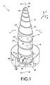
- a helix antenna 10 in accordance with the present invention.
- the antenna 10 typically includes an electrical conductor or component 12 having a substantially helix shape and defining a helix axis 13, a helix support 14 and a mounting base 16 generally supporting the support 14 and the helix 12, and typically having a conventional cup shape 18.
- an electrical conductor or component 12 having a substantially helix shape and defining a helix axis 13, a helix support 14 and a mounting base 16 generally supporting the support 14 and the helix 12, and typically having a conventional cup shape 18.
- the present embodiment 10 is illustrated with one helical conductor 12, a plurality of conductors 12 could be used and mounted on the same support 14 without departing from the scope of the present invention.
- the helix support 14 is mounted on the mounting base 16 of the antenna 10.
- the helix support 14 includes a first or lower flexible sheet 20 or blank that is curlable, from a first substantially rectangular planar or flat development configuration (see Fig. 4 ) into a second substantially cylindrical configuration, to form a cylindrical-shaped support first section 20' for at least partially supporting a first or lower portion of the helix component 12 there around.
- the first section 20' defines a first section axis 22.
- a second or upper flexible sheet 24 or blank is curlable, from a first substantially truncated triangular planar or flat development configuration (see Fig.
- the second section 24' defines a second section axis 26 and is connectable to the first section 20' with the second section axis 26 extending substantially along the first section axis 22, in a substantially co-linear relationship there between.
- the first and second sections 20', 24' support the helix 12 with their axes 13, 22, 26 substantially co-linear with each other.
- the first and second sheets 20, 24 are typically made out of a flexible and partially Radio-Frequency (RF) transparent thermoplastic material, such as, but not limited to, commonly known polyester or polyethylene terephthalate (PET) (including MylarTM), polyimide (including KaptonTM), fluorinated ethylene propylene (FEP) (including polytetrafluoroethylene (PTFE) TeflonTM) and the like materials.
- RF Radio-Frequency
- the first flexible sheet 20 defines generally opposed first or external and second or internal sheet surfaces 28, 30 thereof, respectively.
- the first flexible sheet 20 generally includes a typically thin layer (in the range of approximately two thousand angstroms (2000 A), 0.2 ⁇ m or less, depending on the coating itself) of an antistatic or semi-conductive coating 32 such as, but not limited to, commonly known indium-tin oxide (ITO), germanium, and the like material typically deposited at least on the first sheet surface 28 of the sheet material typically under vacuum condition, although other application processes could be selected such as antistatic paint, spray, dipping and the like.
- ITO indium-tin oxide
- a typical antistatic coating 32 provides a surface resistivity typically varying between about ten to the power six to about ten to the power nine ohms per square (10 6 to 10 9 ⁇ / ⁇ ), considering the RF signal frequency transmitted by the antenna 10.
- both first and second sheet surfaces 28, 30 are coated with the antistatic coating 32.
- the second flexible sheet 24 defines generally opposed third or external and fourth or internal sheet surfaces 34, 36 thereof, respectively.
- the second flexible sheet 24 also generally includes an antistatic coating 32 the third and fourth sheet surfaces including an antistatic coating deposited on the third and fourth sheet surfaces 34, 36 of the corresponding sheet material.
- the first flexible sheet 20 further defines generally opposed first and second interlocking edges 38, 40 that are interlockable to one another in the cylindrical configuration.
- a grounding means typically provides for an electrical grounding between the first and second sheet surfaces 28, 30.
- the first and second sheet surfaces 28, 30 are at least partially in an overlap relationship relative to one another at a position adjacent the first and second interlocking edges 38, 40 respectively, for electrically grounding the two sheet surfaces 28, 30 to one another when the first flexible sheet 20 is in its cylindrical configuration.
- the first flexible sheet 20 includes, at least one, first ground tabs 42 extending substantially outwardly from the first interlocking edge 38 such that the portion of the external sheet surface 28 on the ground tabs 42 is in overlap contact engagement with the internal sheet surface 30 when the first flexible sheet 20 is in its cylindrical configuration, as illustrated in Figs. 2 , 5 and 6 .
- the second flexible sheet 24 further defines generally opposed third and fourth interlocking edges 44, 46 that are interlockable to one another in the conical configuration.
- the third and fourth sheet surfaces 34, 36 are at least partially in an overlap relationship relative to one another at a position adjacent the third and fourth interlocking edges 44, 46 respectively, for electrically grounding the two sheet surfaces 34, 36 to one another when the second flexible sheet 24 is in its conical configuration.
- the second flexible sheet 24 includes, at least one, second ground tabs 48 extending substantially outwardly from the third interlocking edge 44 such that the portion of the external sheet surface 34 on the ground tabs 48 is in overlap contact engagement with the internal sheet surface 36 when the second flexible sheet 24 is in its conical configuration, as illustrated in, Fig. 2 .
- each ground tab 42, 48 includes an opening 50, typically circular, extending there through to allow a typical piece of adhesive tape 52 or the like overlapping the ground tab 42, 48 to have increased available contact surface area with the corresponding underlying sheet surface 28, 30, 34, 36 underneath, as shown in Figs. 3 to 6 .
- the second flexible sheet 24 defines a first or lower interconnecting edge 54 that extends between the third and fourth interlocking edges 44, 46.
- the second flexible sheet 24 includes, at least one, third ground tabs 56 extending outwardly from the first interconnecting edge 54 so as to have the third sheet surface 34 of the third ground tabs 56 electrically connecting to the second sheet surface 30 at a position adjacent a second or upper interconnecting edge 58, being interlockable to the first interconnecting edge 54, that extends between the first and second interlocking edges 38, 40 when the second section 24' is connected to the first section 20'.
- the first flexible sheet 20 defines a third or lower interconnecting edge 60 extending between the first and second interlocking edges 38, 40 and being generally opposite to the second interconnecting edge 58.
- the first section 20' of the helix support 14 is connectable to the mounting base 16 of the antenna 10 with the third interconnecting edge 60 engaging a substantially circular groove 61 thereof, as shown in Fig. 9 .
- the external sheet surface 28 of the support 14 is electrically grounded to the generally electrically conductive mounting base 16 using a grounding means such as at least one substantially elongated ground strap 62 made out of a material similar than the helix support 14 and coated on at least one side or surface thereof with an antistatic coating 32.
- the ground strap 62 has its two longitudinal ends of a coated side in contact by abutting engagement with the helix support 14 and the adjacent mounting base 16 respectively under the pressure of pieces of an adhesive tape 64 or the like.
- a locking means is used to lock the first and second flexible sheets 20, 24 in their respective cylindrical and conical configurations, as well as to provide some physical reference guides of the required shape and/or size of their configurations.
- the locking means allows for interlocking the first and second interlocking edges 38, 40 to one another and at least partially securing the first flexible sheet 20 in its cylindrical configuration.
- the locking means includes, at least one, locking tabs 66 that extend outwardly from one of the first and second interlocking edges 38, 40 and tab receiving slots 68 that extend through the first flexible sheet 20 between the first and second sheet surfaces 28, 30 and substantially parallel to and adjacent the other one of the first and second interlocking edges 38, 40 for at least partially receiving a tip portion 70 (in Fig. 6 and in dotted lines in Figs. 2 and 5 ) of a corresponding locking tab 66.
- the locking means also allows for interlocking the third and fourth interlocking edges 44, 46 to one another and at least partially securing the second flexible sheet 24 in its conical configuration.
- the locking means includes, at least one, locking tabs 72 that extend outwardly from one of the third and fourth interlocking edges 44, 46 and tab receiving slots 74 that extend through the second flexible sheet 24 between the third and fourth sheet surfaces 34, 36 and substantially parallel to and adjacent the other one of the third and fourth interlocking edges 44, 46 for at least partially receiving a tip portion 76 (shown in dotted lines in Fig. 2 ) of a corresponding locking tab 72.
- a connecting means is used to connect the first and second flexible sheets 20, 24 to one another in their respective cylindrical and conical configurations in a end-to-end relationship relative to one another with the second section axis 26 extending substantially along the first section axis 22, as well as to provide some physical reference guides their connection.
- the connecting means includes, at least one, connecting tabs 78 that extend outwardly from one of the first and second interconnecting edges 54, 58 for connection with the other one of the first and second interconnecting edges 54, 58 by resilient abutting engagement there against, using the resiliency or flexibility of the material itself, as shown in Fig. 7 .
- the connecting means includes tab receiving slots 80 that extend through the corresponding of the first and flexible sheets 20, 24 of the other one of the first and second interconnecting edges 54, 58 and substantially parallel to and adjacent the other one of the first and second interconnecting edges 54, 58 for at least partially receiving a tip portion 82 (shown in dotted lines in Fig. 2 ) of a corresponding connecting tab 78.
- the first section 20' is positioned intermediate the second section 24' and the mounting base 16. Accordingly, the second flexible sheet 24 defines a free upper edge 84 that extends between the third and fourth interlocking edges 44, 46 and is generally opposite to the first interconnecting edge 54.
- a small circular hole 86 is typically located on the second flexible sheet 24 adjacent the free upper edge 84 to essentially locate the position of the upper tip end 88 of the helical conductor 12.
- the first flexible sheet 20 typically includes a window 90 or through opening located generally adjacent a tangent point 91 of the lower end 92 of the helical conductor 12 therewith to avoid possible multipaction effects in space applications, with the tangent point 91 facing the window 90.
- the helical conductor 12 being obviously an electrical conductor itself, is typically grounded via the RF signal connection at its lower end 92 adjacent the antenna base 16.
- a bead of adhesive 94 preferably non-conductive, or any other suitable glue, bonding or fastening agent, either continuous or in multiple segments, is typically located at the intersection there between in addition to the existing compressive contact, as schematically illustrated in Fig. 8 .
- Similar beads of adhesive 94 are typically located at the different locking tabs 66, 72 and connecting tabs 78 to secure them in place and along the circular groove 61 to secure the helix support 14 therein, as schematically represented in Figs. 5 and 9 , respectively.
- the adhesive 94 is non-conductive, especially when Passive Inter-Modulation (PIM) products are of a concern. Otherwise, a conductive adhesive 94 could be considered which would also improve the electrical grounding between the different surfaces.
- PIM Passive Inter-Modulation
- the compressive contact also typically ensures an electrical grounding between the first and third external sheet surfaces 28, 34 and the helix conductor 12 whenever required.
- the innovative helical antenna 10 is generally made out of the helix conductor or component 12 and the support component 14, when taken independently in the assembled configuration, are relatively weak or flexible in a respective direction and relatively rigid or stiff in the other. However, when taken together as a whole and structurally interacting or cooperating with each other, they provide an antenna that is relatively rigid in all directions.
- the helix conductor 12 is generally a rigid-type electrically conductive material that is typically obtained from machining, forming (plastically shaped), casting or the like manufacturing process.
- the helix component 12 taken alone, is generally relatively flexible or weak in the axial direction A and in a bending direction B generally transverse to the axial direction A (as a conventional coil spring) when one longitudinal end is secured to a mounting base 16 while it is generally relatively stiff or rigid in the radial direction C (against compressive loads).
- the helix support 14, or first and second flexible sheets 20, 24 in their formed configuration 20', 24', taken alone, is generally relatively rigid in both the axial and bending directions A, B (especially when secured to the circular groove 61) while it is generally relatively flexible in the radial direction C.
- they When assembled together to form the antenna 10, they essentially structurally cooperate with each other such that the respective directional stiffness provide an antenna 10 that is generally relatively rigid in all the axial, bending and radial directions A, B, C.
- the different locking tabs 66, 72 and connecting tabs 78 with their corresponding slots 68, 74, 80 are typically located in-between adjacent windings or spirals of the helix 12 to ensure that the surface underneath the helix 12 is as uniform as possible with no sheet overlap, in order to minimize RF signal losses and multipaction risks.
- the path or pattern of the helix 12 on the first and second flexible sheets 20, 24 is schematically represented in dotted lines in Figs. 4 and 3 respectively.
- the different slots 68, 74, 80 and other openings 50, 86, 88, as well as the different internal and external corners of the first and second flexible sheets 20, 24 are all rounded to avoid conventionally local tears and/or cracks (not shown) that could eventually damage the antenna 10.
- the antenna 110 typically includes an electrical conductor or component 112 made out of a tubular metallic material plastically preshaped to the proper helix dimensions, a helix support 114 and a mounting base 16.
- the helix component 112 is generally supported by the helix support 114, preferably locally using the adhesive 94, at least partially along the helix 112.
- the second embodiment 110 mainly differs from the first one 10 by its first flexible sheet 120 that includes different locking means and grounding means, more suitable for larger size antennae.
- the first flexible sheet by itself, does not form part of the invention.
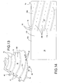
- the flexible sheet 120 defines generally opposed first 202 and second 204 end portions thereof, as shown in Fig. 14 .
- the first and second end portions 202, 204 are adapted to be in an overlap relationship relative to one another when the flexible sheet 120 is in its revolution surface configuration to form the support first section 120', as illustrated in Fig. 12 .
- the first sheet surface 28 of the first end portion 202 is in contact engagement with the second sheet surface 30 of the second end portion 204 of the first section 120' to form the grounding means between the two sheet surfaces 28, 30 coated with an antistatic or semi-conductive coating 32.
- the second end portion 204 typically has a plurality of through holes 206 extending from the first sheet surface 28 to the second sheet surface 30.
- the locking means typically includes an adhesive 94 that substantially fills the plurality of through holes 206 to secure the first and second end portions 202, 204 to one another to maintain the first sheet 120 in its revolution surface configuration.
- the adhesive 94 will have a tendency to partially fill in any gap between the two end portions 202, 204 by capillarity phenomena, to improve the adhesion there between.
- the adhesive 94 could be used to improve the electrical grounding if a conductive adhesive 94 is considered.
- the through holes 206 are substantially uniformly distributed relative to each other to cover the second end portion 204 to uniformly secure the first section 120' in its revolution surface configuration.
- the through holes 206 form spirals located typically half-way in-between spirals of the conductor 112, to avoid any possible mechanical interference therewith, as seen in Fig. 10 .
- a different quantity of connecting tabs 78 are used to connect the second flexible sheet 124 forming the second section 124' of the antenna support 114 to the first section 120'. Also, it is to be noted that the second embodiment 110 does not include any multipaction window 90 at the lower end of the first sheet 120.
- locking tabs 66, 72 are shown as being generally located on a same interlocking edge 40, 46, it would be obvious to one skilled in the art that they could be alternately or differently located on both interlocking edges 38, 40 or 44, 46 of one of the first and second flexible sheets 20, 24, 124 without departing from the scope of the present invention, as evidenced by the lowermost locking tab 66 and corresponding slot 68 of the first flexible sheet 20.
- grounding means including conductive beads of material, could be used to ground the different coated surfaces to one another and perform the same function as the different ground tabs 42, 48, 56 without departing from the scope of the present invention.
- all grounding paths between different antenna components are made redundant for increased reliability of the antenna 10, 110.
- a single piece support or multi-piece support 14, 114 could be considered depending on the physical characteristics of the helical antenna 10, 110 and more specifically of the helical conductor 12, 112 without departing from the scope of the present invention.
- the flexible support 14, 114 could have the shape of any revolution surface, including but not limited to cylindrical, trunco- conical and hemispherical surfaces, when in the formed configuration without departing from the scope of the present invention.
Landscapes
- Details Of Aerials (AREA)
- Support Of Aerials (AREA)
Claims (24)
- Wendelstützvorrichtung (14) zur Unterstützung einer Wendelkomponente (12) einer Wendelantenne (10), wobei die Antenne (10) eine Montagebasis (16) derselben festlegt und die Wendelstützvorrichtung. (14) Folgendos umfasst:- mindestens eine flexible Platte (20), die mindestens teilweise Hochfrequenz-durchlässig und in einer Umlautflächen-Konfiguration gerollt ist und einen Umläufflächen-förmigen Stützabschnitt (20') zur zumindest teilweisen Unterstützung eines Teils der um diesen herum angeordneten wendel komponente (12) bildet, wobei der Stützabschnitt (20') eine Abschnittsachse (22) festlegt und die flexible Platte (20) allgemein einander gegenüber angeordnete erste (26) und zweite (30) Plattenflächen derselben festlegt, wobei die flexible Platte (20) Folgendes umfasst:- ein Erdungsmittel zur elektrischen Erdung der ersten (28) und zweiten (30) Oberfläche der ersten Plattenoberfläche (28)- ein Fixiermittel zum Fixieren der flexiblen Platte (20) im Umlaufflächen-förmigen Stützabschnitt (20');wobei die flexible Platte (20) im allgemeinen einander gegenüber angeordnete erste (38) und zweite (40) Eingriffkante festlegt, die im Umlaufflächen-förmigen Stützabschnitt (20') ineinander eingreifen;
dadurch gekennzeichnet, dass- das Fixiermittel eine Fixierzunge (66) aufweist, die sich von der ersten Eingriffkante (38) auswärts erstreckt, und einen Zungenaufnahmeschlitz (68), der sich durch die flexible Platte (20) zwischen der ersten und der zweiten Plattenoberfläche (28, 30) und im wesentlichen parallel zu der und angrenzend an die zweite(n) Eingriffkante(n) (40) erstreckt, um die Fixierzungc (66) wenigstens teilweise darin aufzunehmen, wobei die Fixierzungen (66) und die Zungenaufnahmeschlitze (68) so ausgeführt sind, dass sie die flexible Platte (20) im Umlaufflächen-förmigen Stützabschnitt (20') festhalten können. - Wendelstützvorrichtung (14) gemäß Anspruch 1, wobei die flexible Platte (20) eine antistatische Beschichtung (32) aufweist, die auf der ersten Plattenoberfläche (28) aufgebraucht ist, die von dem Umlaufflächen-förmigen Stützabschnitts (20') nach außen gewendet ist.
- Wendelantenne (10), die die Wendelkomponente und die Wendelstützvorrichtung gemäß Anspruch 1 umfasst, wobei:- die Wendelkomponente (12) eine Wendelachse (13) festlegt und die Wendelkomponente (12) aus starrem, elektrisch leitenden und zu einer Wendel geformten Material gefertigt ist, wobei die wendelkomponente (12) in Achsrichtung (A) und in einer im allgemeinen quer zur Wendelachse (13) stehenden Biegerichtung (B) flexibel und in einer radialen Kompressionsrichtung (C) starr ist; und- die Wendelstützvorrichtung (14) zumindest teilweise und befestigungsfähig einen Teil der Wendelkomponente (12) um sich herum unterstützt, wobei die Abschnittsachse (22) co-linear im verhältnis zur Wendelachse (13) angeordnet ist, wobei der Stützabschnitt (20') in axialer und in Biegerichtung (A, B) starr und in der radialen Kompressiönsrichtung (C) flexibel ist;- die Wendelkomponente (12) und der Stützabschnitt (14) strukturell zusammenwirken, so dass die Antenne (10) in der Achs-, Biege- und radialen Kompressionsrichtung (A, B, C) starr ist.
- Antenne (10) gemäß Anspruch 3, die des weiteren eine antistatische Beschichtung (32) aufweist, die auf der ersten Plattenoberfläche (28), die von dem Umlaufflächen-förmigen Stützabschnitt (20') nach außen gewendet und auf der Wendelkomponente (12) aufgebracht ist, um die Ableitung einer aufgebauten elektrostatischen Ladung davon zu ermöglichen, wobei die antistatische Beschichtung (32) zumindest teilweise Hochfrequenz-durchlässig ist.
- Wendelstützvorrichtung (14) gemäß Anspruch 2; wobei die erste und die zweite Plattenoberfläche (28, 30) eine darauf aufgebrachte antistatische Beschichtung (32) aufweisen und wobei das Erdungsmittel des Weiteren die erste und die zweite Plattenoberfläche (28, 30) des Umlaufflächen-förmigen Stützabschnitts (20') miteinander erdet.
- Wendelstützvorrichtung (14) gemäß Anspruch 5; wobei das Erdungsmittel eine Erdungszunge (42) umfasst und wobei die ersten und zweiten Plattenoberflächen (28, 30) zumindest teilweise in überlappendem Verhältnis zueinander an einer Position angrenzend an die erste bzw. zweite Eingriffkante (38, 40) des Umlaufflächen-förmigen stützabschnitts (20') angeordnet sind, wobei sich die Erdungszunge (42) von der ersten Eingriffkante (38) auswärts erstreckt, so dass die antistatische Beschichtung (32) auf der ersten Plattenoberfläche (28) der ersten Erdungszunge (42) eine elektrische Verbindung mit der antistatischen Beschichtung (32) auf der zweiten Plattenoberfläche (30) des Umlaufflächen-förmigen Stützabschnitts (20') herstellt.
- Wendelstützvorrichtung (114) gemäß Anspruch 5, wobei die flexible Platte (120) im allgemeinen einander gegenüber angeordnete erste (202) und zweite (204) Endabschnitte derselben festlegt, wobei der erste und zweite Endabschnitt (202, 204) in überlappendem verhältnis , des umlaufflächen-förmigen Stützabschnitts (20') zueinander angeordnet sind und die erste Plattenoberfläche (28) des ersten Endabschnitts (202) in Kontaktverbindung mit der zweiten Plattenoborfläche (30) des zweiten Endabschnitts (204) des Umlaufflächen-förmigen Stützabschnitts (20') ist, um das Erdungsmittel zwischen der ersten und der zweiten Plattenoberfläche (28, 30) auszubilden.
- Wendelstützvorrichtung (14) gemäß Anspruch 1, wobei die Wendelkomponente (12) im Wesentlichen umfänglich und spiralförmig um den Stützabschnitt (20') herum angeordnet ist, wobei die Wendelkomponente (12) entlang diesem Abschnitt, einen vorgegebenen Tangentialpunkt (91) festlegt, wobei sich die Wendelkomponente (12) an dem vorgegebenen Tangentialpunkt (91) im wesentlichen tangential vom Stützabschnitt (20') weg erstreckt und der Stützabschnitt (20') angrenzend an den vorgegebenen Tangentialpunkt (91) einen Durchlass (90) aufweist.
- Wendelantenne (10), die eine erdungsfähige Wendelkomponente (12) umfasst, welche zumindest teilweise und befestigungsfähig von den Wendelstützvorrichtung (14) gemäß Anspruch 1 unterstützt wird.
- Antenne (10) gemäß Anspruch 9, wobei:- die Wendelkomponente (12) aus einem starren, elektrisch leitenden und zu einer Wendel geformten Material gefertigt ist und eine Wendelachse (13) festlegt, wobei die Wendelkomponente (12) in Achsrichtung (A) und in einer im allgemeinen quer zur Wendelachse (13) stehenden Biegerichtung (B) flexibel und in einer radialen Kompressionsrichtung (C) starr ist; und- die Abschnittsachse (22) in co-linearem Verhältnis zur Wendelachse (13) steht, wenn sich die flexible Platte (20) in der Umlauftlächen-Konfiguration befindet;- der Stützabschnitt (14) in Achs- und Biegerichtung (A, B) starr und in der radialen Kompressionsrichtung (C) flexibel ist und wobei die Wendelkomponente (12) und der Stützabschnitt (14) strukturell zusammenwirken; so dass die Antenne (10) in der Achs-, Biege- und radialen Kompressionsrichtung (A, B, C) starr ist, wenn der Stützabschnitt (14) die Wendelkomponente (12) darum herum befestigungsfähig unterstützt.
- Antenne (10) gemäß Anspruch 10, wobei der Wendelteil (12) umfänglich und spiralförmig um den Stützabschnitt (20') angeordnete ist und der Wendelteil (12) einen vorgegebenen Tangentialpunkt (91) entlang diesem festlegt, wobei sich der Wendelteil (12) an dem vorgegebenen Tangentialpunkt (91) tangential weg von dem Stützabschnitt (20') erstreckt und der Stützabschnitt (20') einen Durchlass (.90) aufweist, der angrenzend an den vorgegebenen Tangentialpunkt (91) angeordnet ist.
- Wendelstützvorrichtung (14) gemäß Anspruch 1, wobei die mindestens eine flexible Platte Folgendes umfasst:- eine erste flexible Platte (20), die mindestens teilweise Hochfrequenz-durchlässig und in einer ersten Umlaufflächen-Konfiguration gerollt ist, um einen ersten Umlaufflächen-förmigen. Stützabschnitt (20') zur zumindest teilweisen Unterstützung eine ersten Teils der um diesen herum angeordneten Wendelkomponente (12) zu bilden, wobei der erste Abschnitt (20') eine erste Abschnittsachse (22) festlegt; und- eine zweite flexible Platte (24), die mindestens teilweise Hochfrequenz-durchlassig und in einer zweiten Umlaufflächen-Konfiguration gerollt ist, um einen zweiten Umlaufflächen-förmigen Stützabschnitt (24') zur zumindest teilweisen Unterstützung eines zweiten Teile der um diesen herum angeordneten Wendelkomponente (12) zu bilden, wobei der zweite Abschnitt (24') eine zweite Abschnittsachse (26) festlegt und der zweite Abschnitt (24') und der erste Abschnitt (20') mechanisch in einer Stoßverbindung relativ miteinander verbunden sind und wobei sich die zweite Abschnittsachse (26) entlang der ersten Abschnittsachse (22) erstreckt.
- Wendelstützvorrichtung (14) gemäß Anspruch 12, wobei die erste und die zweite Umlaufflächen-Konfigurationen zylindrische und konische Konfigurationen zur Ausbildung zylindrischer (20') bzw. konischer (24') Stützabschnitte sind.
- Wendelstützvorrichtung (14) gemäß Anspruch 13, wobei die erste (28) und die zweite (30) Plattenoberfläche eine darauf aufgebrachte antistatische Beschichtung (32) umfassen und die Wendelstützvorrichtung (14) des Weiteren ein Erdungsmittel umfasst, das die erste und die zweite Plattenoberfläche (28, 30) aneinander elektrisch erdet.
- Wendelstützvorrichtung (14) gemäß Anspruch 14, wobei die erste und die zweite Plattenoberfläche (28, 30) zumindest teilweise in, überlappendem Verhaltnis zueinander an einer Position angrenzend, an die erste bzw. zweite Eingriffkante (38, 40) angeordnet sind, wobei die erste flexible Platte (20) eine erste Erdungszunge (42) aufweiset, die sich von der ersten Eingriffkante (38) auswärts erstreckt, so dass die erste Plattenoberfläche (28) der ersten Erdungszunge (42) eine elektrische Verbindung mit der zweiten Plattenoberfläche (30) herstellt und damit das Erdungsmittel ausbildet.
- Wendelstützvorrichtung (14) gemäß Anspruch 15, wobei die zweites flexible Platte (24) im allgemeinen einander gegenüber angeordnete dritte (34) und vierte (36) Plattenoberflächen derselben festlegt, wobei die dritte und die vierte Plattenoberfläche (34, 36) mit einer antistatischen Beschichtung (32) versehen sind.
- Wendelstützvorrichtung (14) gemäß Anspruch 16, wobei die zweite flexible Platte (24) im allgemeinen einander gegenüber angeordnete, ineinander eingreifende dritte (44) und vierte (46) Eingriffkanten festlegt, wobei die dritte und die vierte Plattenoberfläche (34, 36) zumindest teilweise in überlappendem Verhältnis zueinander an einer Position angrenzend an die dritte bzw. vierte Eingriffkante (44, 46) stehen, wobei die zweite flexible Platte (24) eine zweite Erdungszunge (48) umfasst, wobei sich die zweite Erdungszunge (48) von der dritten Eingriffkante (44) auswärts erstreckt, so dass die dritte Plattenoberfäche (34) der zweiten Erdungszunge (48) mit der vierten Plattenoberfläche (36) elektrisch verbunden ist.
- Wendelstützvorrichtung (14) gemäß Anspruch 17, wobei die zweite flexible Platte (24) eine erste Eingriffkante (54) festlegt, dies sich zwischen der dritten und der vierten Eingriffkante (44, 46) erstreckt, wobei die zweite flexible Platte (24) eine dritte Erdungszunge (56) umfasst, und sich die dritte Erdungszunge (56) von der ersten Eingriffkante (54) auswärts erstreckt, so dass die dritte Plattenoberfläche (34) der dritten Erdungszunge (56) eine elektrische Verbindung mit der zweiten Plattenoberfläche (30) erstellt, wenn der zweite Abschnitt (24') mit dem ersten Abschnitt (20') verbunden ist.
- Wendelstutzvorrichtung (14) gemäß Anspruch 18, die des weiteren ein Verbindungsmittel zur mechanischen Verbindung des ersten und des zweiten Abschnitts (20', 24') umfasst.
- Wendelstützvorrichtung (14) gemäß Anspruch 19, wobei das Verbindungsmittel eine Verbindungszunge (78) und einen Zungenaufnahmeschlitz (80) umfasst, der die verbindungszunge (78) zumindest teilweise aufnimmt, um den ersten und zweiten Abschnitt (20', 24') in einer Stoßverbindung miteinander zu verbinden, wobei sich die zweite Abschnittsachse (26) im Wesentlichen entlang der ersten Abschnittsachse (22) ersteckt.
- Wendelstützvorrichtung (14) gemäß Anspruch 20, wobei die erste flexible Platte (20) eine zweite Verbindungkante (58) festlegt, die sich zwischen der ersten und der zweiten Eingriffkante (38, 40) erstreckt, wobei die zweite Verbindungskante (58) mit der ersten Verbindungskante (54) verbunden ist, wobei sich die Verbindungszunge (78) von einer (58) der ersten oder der zweiten Verbindungskante (54, 58) auswärts erstreckt und sich der Aufnahmeschlitz (80) durch die entsprechende erste und zweite flexible Platte (20, 29) der anderen (54) der ersten und zweiten Verbindungskante (54, 58) und im Wesentlichen parallel zu der anderen (54) der ersten und zweiten Verbindungskante (54, 58) und angrenzend an diese erstreckt.
- Wendelstützvorrichtung (14) gemäß Anspruch 13, wobei die zweite flexible Platte (24) im allgemeinen einander gegenüber angeordnete dritte (34) und vierte (36) Plattenoberflächen derselben festlegt, wobei die erste und die dritte Plattenoberfläche (28, 34) im allgemeinen radial auswärts vom ersten bzw. zweiten Abschnitt (20', 24') gewendet sind und mit einer antistatischen Beschichtung (32) darauf versehen sind, um die Ableitung einer aufgebauten elektrostatischen Ladung zu ermöglichen.
- Wendelstützvorrichtung (14) gemäß Anspruch 14, wobei die Montagebasis (16) elektrisch leitend ist und das Erdungsmittel die erste flexible Platte (20) des weiteren an der Montagebasis (16) erdet.
- Wendelstützvorrichtung (14) gemäß Anspruch 23, wobei das Erdungsmittel einen im allgemeinen länglich und flexiblen Erdungsstreifen (62) umfasst, der im allgemeinen einander gegenüber angeordnete Hauptstreifenflächen und im allgemeinen einander gegenüber angeordnete Streifen-Längsenden aufweist, wobei mindestens eine der Hauptstreifenflächen eine antistatischen Oberfläche ist und die Streifen-Längsenden der antistatischen Oberfläche mit der ersten Plattenoberfläche (28) bzw. der Montagebasis (16) elektrisch verbunden sind, um die Wendelstützvorrichtung (14) an der Montagebasis (16) elektrisch zu erden.
Applications Claiming Priority (2)
| Application Number | Priority Date | Filing Date | Title |
|---|---|---|---|
| US47922803P | 2003-06-18 | 2003-06-18 | |
| US479228P | 2003-06-18 |
Publications (2)
| Publication Number | Publication Date |
|---|---|
| EP1489685A1 EP1489685A1 (de) | 2004-12-22 |
| EP1489685B1 true EP1489685B1 (de) | 2008-08-20 |
Family
ID=33418479
Family Applications (1)
| Application Number | Title | Priority Date | Filing Date |
|---|---|---|---|
| EP04291524A Expired - Lifetime EP1489685B1 (de) | 2003-06-18 | 2004-06-17 | Stützvorrichtung für eine Wendelantenne und Wendelantenne mit einer solchen Stützvorrichtung |
Country Status (4)
| Country | Link |
|---|---|
| US (1) | US7038636B2 (de) |
| EP (1) | EP1489685B1 (de) |
| AT (1) | ATE405970T1 (de) |
| DE (1) | DE602004015889D1 (de) |
Families Citing this family (140)
| Publication number | Priority date | Publication date | Assignee | Title |
|---|---|---|---|---|
| FR2866479A1 (fr) * | 2004-02-12 | 2005-08-19 | Thomson Licensing Sa | Procede de fabrication d'une antenne et/ou d'un reseau d'antennes, antenne et/ou reseau d'antennes fabriques selon un tel procede |
| US7142171B1 (en) | 2005-04-14 | 2006-11-28 | Lockheed Martin Corporation | Helix radiating elements for high power applications |
| WO2006114270A1 (de) * | 2005-04-26 | 2006-11-02 | Hirschmann Car Communication Gmbh | Antennenrute mit innenliegendem ummantelten stab mit einer wicklung und einem aussenmantel darüber |
| TWM284087U (en) * | 2005-08-26 | 2005-12-21 | Aonvision Technology Corp | Broadband planar dipole antenna |
| US7286099B1 (en) * | 2005-09-02 | 2007-10-23 | Lockheed Martin Corporation | Rotation-independent helical antenna |
| US7336241B2 (en) * | 2005-09-15 | 2008-02-26 | Qualcomm Incorporated | GPS radome-mounted antenna assembly |
| US20080122719A1 (en) * | 2006-08-15 | 2008-05-29 | Joymax Electronics Co., Ltd. | Antenna device |
| US8038815B2 (en) * | 2007-07-17 | 2011-10-18 | Qualcomm Incorporated | Fluorescent dye to improve primer coverage accuracy for bonding applications |
| US20100073259A1 (en) * | 2008-09-25 | 2010-03-25 | Joymax Electronics Co., Ltd. | Antenna device |
| DE112009005121B4 (de) * | 2009-08-06 | 2018-07-05 | Indian Space Research Organisation Of Isro | Gedruckte, quasi-konische Streifenwendel-Arrayantenne |
| US9118118B2 (en) * | 2009-10-16 | 2015-08-25 | Ems Technologies Canada, Ltd. | Increased gain in an array antenna through optimal suspension of piece-wise linear conductors |
| JP2012019419A (ja) * | 2010-07-08 | 2012-01-26 | Fujikura Ltd | ヘリカルアンテナ、及び、ヘリカルアンテナの製造方法 |
| US8692722B2 (en) | 2011-02-01 | 2014-04-08 | Phoenix Contact Development and Manufacturing, Inc. | Wireless field device or wireless field device adapter with removable antenna module |
| DE102013104699A1 (de) * | 2013-05-07 | 2014-11-13 | Endress + Hauser Gmbh + Co. Kg | Vorrichtung zur Bestimmung des Füllstandes mittels einer Helixantenne |
| US9999038B2 (en) | 2013-05-31 | 2018-06-12 | At&T Intellectual Property I, L.P. | Remote distributed antenna system |
| US9525524B2 (en) | 2013-05-31 | 2016-12-20 | At&T Intellectual Property I, L.P. | Remote distributed antenna system |
| US8897697B1 (en) | 2013-11-06 | 2014-11-25 | At&T Intellectual Property I, Lp | Millimeter-wave surface-wave communications |
| FR3022403B1 (fr) * | 2014-06-11 | 2016-06-24 | Renault Sa | Systeme de communication sans-fil et vehicule equipe d'un tel systeme |
| CN104300205B (zh) * | 2014-08-22 | 2017-08-25 | 大连海事大学 | 一种液态金属螺旋天线 |
| US9768833B2 (en) | 2014-09-15 | 2017-09-19 | At&T Intellectual Property I, L.P. | Method and apparatus for sensing a condition in a transmission medium of electromagnetic waves |
| US10063280B2 (en) | 2014-09-17 | 2018-08-28 | At&T Intellectual Property I, L.P. | Monitoring and mitigating conditions in a communication network |
| US9615269B2 (en) | 2014-10-02 | 2017-04-04 | At&T Intellectual Property I, L.P. | Method and apparatus that provides fault tolerance in a communication network |
| US9685992B2 (en) | 2014-10-03 | 2017-06-20 | At&T Intellectual Property I, L.P. | Circuit panel network and methods thereof |
| US9503189B2 (en) | 2014-10-10 | 2016-11-22 | At&T Intellectual Property I, L.P. | Method and apparatus for arranging communication sessions in a communication system |
| US9973299B2 (en) | 2014-10-14 | 2018-05-15 | At&T Intellectual Property I, L.P. | Method and apparatus for adjusting a mode of communication in a communication network |
| US9780834B2 (en) | 2014-10-21 | 2017-10-03 | At&T Intellectual Property I, L.P. | Method and apparatus for transmitting electromagnetic waves |
| US9627768B2 (en) | 2014-10-21 | 2017-04-18 | At&T Intellectual Property I, L.P. | Guided-wave transmission device with non-fundamental mode propagation and methods for use therewith |
| US9653770B2 (en) | 2014-10-21 | 2017-05-16 | At&T Intellectual Property I, L.P. | Guided wave coupler, coupling module and methods for use therewith |
| US9577306B2 (en) | 2014-10-21 | 2017-02-21 | At&T Intellectual Property I, L.P. | Guided-wave transmission device and methods for use therewith |
| US9312919B1 (en) | 2014-10-21 | 2016-04-12 | At&T Intellectual Property I, Lp | Transmission device with impairment compensation and methods for use therewith |
| US9769020B2 (en) | 2014-10-21 | 2017-09-19 | At&T Intellectual Property I, L.P. | Method and apparatus for responding to events affecting communications in a communication network |
| US10009067B2 (en) | 2014-12-04 | 2018-06-26 | At&T Intellectual Property I, L.P. | Method and apparatus for configuring a communication interface |
| US10243784B2 (en) | 2014-11-20 | 2019-03-26 | At&T Intellectual Property I, L.P. | System for generating topology information and methods thereof |
| US10340573B2 (en) | 2016-10-26 | 2019-07-02 | At&T Intellectual Property I, L.P. | Launcher with cylindrical coupling device and methods for use therewith |
| US9997819B2 (en) | 2015-06-09 | 2018-06-12 | At&T Intellectual Property I, L.P. | Transmission medium and method for facilitating propagation of electromagnetic waves via a core |
| US9800327B2 (en) | 2014-11-20 | 2017-10-24 | At&T Intellectual Property I, L.P. | Apparatus for controlling operations of a communication device and methods thereof |
| US9954287B2 (en) | 2014-11-20 | 2018-04-24 | At&T Intellectual Property I, L.P. | Apparatus for converting wireless signals and electromagnetic waves and methods thereof |
| US9461706B1 (en) | 2015-07-31 | 2016-10-04 | At&T Intellectual Property I, Lp | Method and apparatus for exchanging communication signals |
| US9742462B2 (en) | 2014-12-04 | 2017-08-22 | At&T Intellectual Property I, L.P. | Transmission medium and communication interfaces and methods for use therewith |
| US9544006B2 (en) | 2014-11-20 | 2017-01-10 | At&T Intellectual Property I, L.P. | Transmission device with mode division multiplexing and methods for use therewith |
| US9876570B2 (en) | 2015-02-20 | 2018-01-23 | At&T Intellectual Property I, Lp | Guided-wave transmission device with non-fundamental mode propagation and methods for use therewith |
| US9749013B2 (en) | 2015-03-17 | 2017-08-29 | At&T Intellectual Property I, L.P. | Method and apparatus for reducing attenuation of electromagnetic waves guided by a transmission medium |
| US9705561B2 (en) | 2015-04-24 | 2017-07-11 | At&T Intellectual Property I, L.P. | Directional coupling device and methods for use therewith |
| US10224981B2 (en) | 2015-04-24 | 2019-03-05 | At&T Intellectual Property I, Lp | Passive electrical coupling device and methods for use therewith |
| US9793954B2 (en) | 2015-04-28 | 2017-10-17 | At&T Intellectual Property I, L.P. | Magnetic coupling device and methods for use therewith |
| US9490869B1 (en) | 2015-05-14 | 2016-11-08 | At&T Intellectual Property I, L.P. | Transmission medium having multiple cores and methods for use therewith |
| US9871282B2 (en) | 2015-05-14 | 2018-01-16 | At&T Intellectual Property I, L.P. | At least one transmission medium having a dielectric surface that is covered at least in part by a second dielectric |
| US9748626B2 (en) | 2015-05-14 | 2017-08-29 | At&T Intellectual Property I, L.P. | Plurality of cables having different cross-sectional shapes which are bundled together to form a transmission medium |
| US10650940B2 (en) | 2015-05-15 | 2020-05-12 | At&T Intellectual Property I, L.P. | Transmission medium having a conductive material and methods for use therewith |
| US9917341B2 (en) | 2015-05-27 | 2018-03-13 | At&T Intellectual Property I, L.P. | Apparatus and method for launching electromagnetic waves and for modifying radial dimensions of the propagating electromagnetic waves |
| US9912381B2 (en) | 2015-06-03 | 2018-03-06 | At&T Intellectual Property I, Lp | Network termination and methods for use therewith |
| US10812174B2 (en) | 2015-06-03 | 2020-10-20 | At&T Intellectual Property I, L.P. | Client node device and methods for use therewith |
| US9866309B2 (en) | 2015-06-03 | 2018-01-09 | At&T Intellectual Property I, Lp | Host node device and methods for use therewith |
| US9913139B2 (en) | 2015-06-09 | 2018-03-06 | At&T Intellectual Property I, L.P. | Signal fingerprinting for authentication of communicating devices |
| US9820146B2 (en) | 2015-06-12 | 2017-11-14 | At&T Intellectual Property I, L.P. | Method and apparatus for authentication and identity management of communicating devices |
| US9509415B1 (en) | 2015-06-25 | 2016-11-29 | At&T Intellectual Property I, L.P. | Methods and apparatus for inducing a fundamental wave mode on a transmission medium |
| US9640850B2 (en) | 2015-06-25 | 2017-05-02 | At&T Intellectual Property I, L.P. | Methods and apparatus for inducing a non-fundamental wave mode on a transmission medium |
| US9865911B2 (en) | 2015-06-25 | 2018-01-09 | At&T Intellectual Property I, L.P. | Waveguide system for slot radiating first electromagnetic waves that are combined into a non-fundamental wave mode second electromagnetic wave on a transmission medium |
| US10148016B2 (en) | 2015-07-14 | 2018-12-04 | At&T Intellectual Property I, L.P. | Apparatus and methods for communicating utilizing an antenna array |
| US9853342B2 (en) | 2015-07-14 | 2017-12-26 | At&T Intellectual Property I, L.P. | Dielectric transmission medium connector and methods for use therewith |
| US10205655B2 (en) | 2015-07-14 | 2019-02-12 | At&T Intellectual Property I, L.P. | Apparatus and methods for communicating utilizing an antenna array and multiple communication paths |
| US9882257B2 (en) | 2015-07-14 | 2018-01-30 | At&T Intellectual Property I, L.P. | Method and apparatus for launching a wave mode that mitigates interference |
| US9847566B2 (en) | 2015-07-14 | 2017-12-19 | At&T Intellectual Property I, L.P. | Method and apparatus for adjusting a field of a signal to mitigate interference |
| US9628116B2 (en) | 2015-07-14 | 2017-04-18 | At&T Intellectual Property I, L.P. | Apparatus and methods for transmitting wireless signals |
| US10044409B2 (en) | 2015-07-14 | 2018-08-07 | At&T Intellectual Property I, L.P. | Transmission medium and methods for use therewith |
| US10090606B2 (en) | 2015-07-15 | 2018-10-02 | At&T Intellectual Property I, L.P. | Antenna system with dielectric array and methods for use therewith |
| US9871283B2 (en) | 2015-07-23 | 2018-01-16 | At&T Intellectual Property I, Lp | Transmission medium having a dielectric core comprised of plural members connected by a ball and socket configuration |
| US9749053B2 (en) | 2015-07-23 | 2017-08-29 | At&T Intellectual Property I, L.P. | Node device, repeater and methods for use therewith |
| US9912027B2 (en) | 2015-07-23 | 2018-03-06 | At&T Intellectual Property I, L.P. | Method and apparatus for exchanging communication signals |
| US9948333B2 (en) | 2015-07-23 | 2018-04-17 | At&T Intellectual Property I, L.P. | Method and apparatus for wireless communications to mitigate interference |
| US9967173B2 (en) | 2015-07-31 | 2018-05-08 | At&T Intellectual Property I, L.P. | Method and apparatus for authentication and identity management of communicating devices |
| US9735833B2 (en) | 2015-07-31 | 2017-08-15 | At&T Intellectual Property I, L.P. | Method and apparatus for communications management in a neighborhood network |
| US9904535B2 (en) | 2015-09-14 | 2018-02-27 | At&T Intellectual Property I, L.P. | Method and apparatus for distributing software |
| US9769128B2 (en) | 2015-09-28 | 2017-09-19 | At&T Intellectual Property I, L.P. | Method and apparatus for encryption of communications over a network |
| US9729197B2 (en) | 2015-10-01 | 2017-08-08 | At&T Intellectual Property I, L.P. | Method and apparatus for communicating network management traffic over a network |
| US9876264B2 (en) | 2015-10-02 | 2018-01-23 | At&T Intellectual Property I, Lp | Communication system, guided wave switch and methods for use therewith |
| US10355367B2 (en) | 2015-10-16 | 2019-07-16 | At&T Intellectual Property I, L.P. | Antenna structure for exchanging wireless signals |
| US9860075B1 (en) | 2016-08-26 | 2018-01-02 | At&T Intellectual Property I, L.P. | Method and communication node for broadband distribution |
| US10811767B2 (en) | 2016-10-21 | 2020-10-20 | At&T Intellectual Property I, L.P. | System and dielectric antenna with convex dielectric radome |
| US10374316B2 (en) | 2016-10-21 | 2019-08-06 | At&T Intellectual Property I, L.P. | System and dielectric antenna with non-uniform dielectric |
| US10312567B2 (en) | 2016-10-26 | 2019-06-04 | At&T Intellectual Property I, L.P. | Launcher with planar strip antenna and methods for use therewith |
| US10498044B2 (en) | 2016-11-03 | 2019-12-03 | At&T Intellectual Property I, L.P. | Apparatus for configuring a surface of an antenna |
| US10225025B2 (en) | 2016-11-03 | 2019-03-05 | At&T Intellectual Property I, L.P. | Method and apparatus for detecting a fault in a communication system |
| US10291334B2 (en) | 2016-11-03 | 2019-05-14 | At&T Intellectual Property I, L.P. | System for detecting a fault in a communication system |
| US10224634B2 (en) | 2016-11-03 | 2019-03-05 | At&T Intellectual Property I, L.P. | Methods and apparatus for adjusting an operational characteristic of an antenna |
| US10340601B2 (en) | 2016-11-23 | 2019-07-02 | At&T Intellectual Property I, L.P. | Multi-antenna system and methods for use therewith |
| US10535928B2 (en) | 2016-11-23 | 2020-01-14 | At&T Intellectual Property I, L.P. | Antenna system and methods for use therewith |
| US10340603B2 (en) | 2016-11-23 | 2019-07-02 | At&T Intellectual Property I, L.P. | Antenna system having shielded structural configurations for assembly |
| US10178445B2 (en) | 2016-11-23 | 2019-01-08 | At&T Intellectual Property I, L.P. | Methods, devices, and systems for load balancing between a plurality of waveguides |
| US10090594B2 (en) | 2016-11-23 | 2018-10-02 | At&T Intellectual Property I, L.P. | Antenna system having structural configurations for assembly |
| US10361489B2 (en) | 2016-12-01 | 2019-07-23 | At&T Intellectual Property I, L.P. | Dielectric dish antenna system and methods for use therewith |
| US10305190B2 (en) | 2016-12-01 | 2019-05-28 | At&T Intellectual Property I, L.P. | Reflecting dielectric antenna system and methods for use therewith |
| US10755542B2 (en) | 2016-12-06 | 2020-08-25 | At&T Intellectual Property I, L.P. | Method and apparatus for surveillance via guided wave communication |
| US9927517B1 (en) | 2016-12-06 | 2018-03-27 | At&T Intellectual Property I, L.P. | Apparatus and methods for sensing rainfall |
| US10727599B2 (en) | 2016-12-06 | 2020-07-28 | At&T Intellectual Property I, L.P. | Launcher with slot antenna and methods for use therewith |
| US10382976B2 (en) | 2016-12-06 | 2019-08-13 | At&T Intellectual Property I, L.P. | Method and apparatus for managing wireless communications based on communication paths and network device positions |
| US10694379B2 (en) | 2016-12-06 | 2020-06-23 | At&T Intellectual Property I, L.P. | Waveguide system with device-based authentication and methods for use therewith |
| US10020844B2 (en) | 2016-12-06 | 2018-07-10 | T&T Intellectual Property I, L.P. | Method and apparatus for broadcast communication via guided waves |
| US10637149B2 (en) | 2016-12-06 | 2020-04-28 | At&T Intellectual Property I, L.P. | Injection molded dielectric antenna and methods for use therewith |
| US10439675B2 (en) | 2016-12-06 | 2019-10-08 | At&T Intellectual Property I, L.P. | Method and apparatus for repeating guided wave communication signals |
| US10326494B2 (en) | 2016-12-06 | 2019-06-18 | At&T Intellectual Property I, L.P. | Apparatus for measurement de-embedding and methods for use therewith |
| US10135145B2 (en) | 2016-12-06 | 2018-11-20 | At&T Intellectual Property I, L.P. | Apparatus and methods for generating an electromagnetic wave along a transmission medium |
| US10819035B2 (en) | 2016-12-06 | 2020-10-27 | At&T Intellectual Property I, L.P. | Launcher with helical antenna and methods for use therewith |
| US10139820B2 (en) | 2016-12-07 | 2018-11-27 | At&T Intellectual Property I, L.P. | Method and apparatus for deploying equipment of a communication system |
| US10389029B2 (en) | 2016-12-07 | 2019-08-20 | At&T Intellectual Property I, L.P. | Multi-feed dielectric antenna system with core selection and methods for use therewith |
| US10243270B2 (en) | 2016-12-07 | 2019-03-26 | At&T Intellectual Property I, L.P. | Beam adaptive multi-feed dielectric antenna system and methods for use therewith |
| US10027397B2 (en) | 2016-12-07 | 2018-07-17 | At&T Intellectual Property I, L.P. | Distributed antenna system and methods for use therewith |
| US10547348B2 (en) | 2016-12-07 | 2020-01-28 | At&T Intellectual Property I, L.P. | Method and apparatus for switching transmission mediums in a communication system |
| US10359749B2 (en) | 2016-12-07 | 2019-07-23 | At&T Intellectual Property I, L.P. | Method and apparatus for utilities management via guided wave communication |
| US10446936B2 (en) | 2016-12-07 | 2019-10-15 | At&T Intellectual Property I, L.P. | Multi-feed dielectric antenna system and methods for use therewith |
| US10168695B2 (en) | 2016-12-07 | 2019-01-01 | At&T Intellectual Property I, L.P. | Method and apparatus for controlling an unmanned aircraft |
| US9893795B1 (en) | 2016-12-07 | 2018-02-13 | At&T Intellectual Property I, Lp | Method and repeater for broadband distribution |
| US10601494B2 (en) | 2016-12-08 | 2020-03-24 | At&T Intellectual Property I, L.P. | Dual-band communication device and method for use therewith |
| US10777873B2 (en) | 2016-12-08 | 2020-09-15 | At&T Intellectual Property I, L.P. | Method and apparatus for mounting network devices |
| US10411356B2 (en) | 2016-12-08 | 2019-09-10 | At&T Intellectual Property I, L.P. | Apparatus and methods for selectively targeting communication devices with an antenna array |
| US10938108B2 (en) | 2016-12-08 | 2021-03-02 | At&T Intellectual Property I, L.P. | Frequency selective multi-feed dielectric antenna system and methods for use therewith |
| US10069535B2 (en) | 2016-12-08 | 2018-09-04 | At&T Intellectual Property I, L.P. | Apparatus and methods for launching electromagnetic waves having a certain electric field structure |
| US9998870B1 (en) | 2016-12-08 | 2018-06-12 | At&T Intellectual Property I, L.P. | Method and apparatus for proximity sensing |
| US10530505B2 (en) | 2016-12-08 | 2020-01-07 | At&T Intellectual Property I, L.P. | Apparatus and methods for launching electromagnetic waves along a transmission medium |
| US10916969B2 (en) | 2016-12-08 | 2021-02-09 | At&T Intellectual Property I, L.P. | Method and apparatus for providing power using an inductive coupling |
| US10103422B2 (en) | 2016-12-08 | 2018-10-16 | At&T Intellectual Property I, L.P. | Method and apparatus for mounting network devices |
| US10326689B2 (en) | 2016-12-08 | 2019-06-18 | At&T Intellectual Property I, L.P. | Method and system for providing alternative communication paths |
| US9911020B1 (en) | 2016-12-08 | 2018-03-06 | At&T Intellectual Property I, L.P. | Method and apparatus for tracking via a radio frequency identification device |
| US10389037B2 (en) | 2016-12-08 | 2019-08-20 | At&T Intellectual Property I, L.P. | Apparatus and methods for selecting sections of an antenna array and use therewith |
| US9838896B1 (en) | 2016-12-09 | 2017-12-05 | At&T Intellectual Property I, L.P. | Method and apparatus for assessing network coverage |
| US10264586B2 (en) | 2016-12-09 | 2019-04-16 | At&T Mobility Ii Llc | Cloud-based packet controller and methods for use therewith |
| US10340983B2 (en) | 2016-12-09 | 2019-07-02 | At&T Intellectual Property I, L.P. | Method and apparatus for surveying remote sites via guided wave communications |
| US9973940B1 (en) | 2017-02-27 | 2018-05-15 | At&T Intellectual Property I, L.P. | Apparatus and methods for dynamic impedance matching of a guided wave launcher |
| US10298293B2 (en) | 2017-03-13 | 2019-05-21 | At&T Intellectual Property I, L.P. | Apparatus of communication utilizing wireless network devices |
| CA3117582A1 (en) | 2018-10-25 | 2020-04-30 | National Research Council Of Canada | Printed film electrostatic concentrator for radon detection |
| CN110474145B (zh) * | 2019-07-24 | 2020-11-20 | 西安空间无线电技术研究所 | 一种新型低pim伞状天线 |
| US11682841B2 (en) | 2021-09-16 | 2023-06-20 | Eagle Technology, Llc | Communications device with helically wound conductive strip and related antenna devices and methods |
| US12027762B2 (en) | 2022-02-10 | 2024-07-02 | Eagle Technology, Llc | Communications device with helically wound conductive strip with lens and related antenna device and method |
| CN114497975B (zh) * | 2022-04-07 | 2022-08-26 | 西安星通通信科技有限公司 | 具有螺旋线缆升降支撑结构的天线、螺旋线缆升降支撑结构 |
| US12230880B2 (en) | 2022-10-20 | 2025-02-18 | Eagle Technology, Llc | Communications device with rhombus shaped-slot radiating antenna and related antenna device and method |
| US12294147B2 (en) | 2022-10-20 | 2025-05-06 | Eagle Technology, Llc | Communications device with helical slot radiating antenna and related antenna device and method |
| CN115832668B (zh) * | 2022-11-25 | 2025-08-15 | 哈尔滨工业大学 | 一种螺旋天线装置 |
| US12584785B2 (en) | 2023-04-28 | 2026-03-24 | Eagle Technology, Llc | Distributed acoustic sensing (DAS) system for acoustic event detection based upon covariance matrices and related methods |
| US12560475B2 (en) | 2023-04-28 | 2026-02-24 | Eagle Technology, Llc | Distributed acoustic sensing (DAS) system for acoustic event detection using machine learning network selected by game theoretic model and related methods |
| US12438260B1 (en) | 2024-12-20 | 2025-10-07 | Saltenna Inc. | Surface electromagnetic wave antenna |
Family Cites Families (34)
| Publication number | Priority date | Publication date | Assignee | Title |
|---|---|---|---|---|
| US20670A (en) * | 1858-06-22 | Portfolio-pile | ||
| US2958081A (en) * | 1959-06-30 | 1960-10-25 | Univ Illinois | Unidirectional broadband antenna comprising modified balanced equiangular spiral |
| US3633210A (en) * | 1967-05-26 | 1972-01-04 | Philco Ford Corp | Unbalanced conical spiral antenna |
| CH499888A (fr) | 1967-12-15 | 1970-11-30 | Onera (Off Nat Aerospatiale) | Antenne à un seul conducteur enroulé hélicoïdalement de dimensions réduites, et procédé pour sa fabrication |
| US3681772A (en) * | 1970-12-31 | 1972-08-01 | Trw Inc | Modulated arm width spiral antenna |
| US4945363A (en) | 1984-05-25 | 1990-07-31 | Revlon, Inc. | Conical spiral antenna |
| FR2624656B1 (fr) | 1987-12-10 | 1990-05-18 | Centre Nat Etd Spatiales | Antenne de type helice et son procede de realisation |
| JPH0374906A (ja) * | 1989-08-16 | 1991-03-29 | Toyo Commun Equip Co Ltd | 4線分数巻ヘリカルアンテナの製造方法 |
| FR2654554B1 (fr) | 1989-11-10 | 1992-07-31 | France Etat | Antenne en helice, quadrifilaire, resonnante bicouche. |
| EP0465658B1 (de) * | 1990-01-08 | 1996-10-16 | Toyo Communication Equipment Co. Ltd. | Wendelantenne mit geteilter vierdrahtwicklung und verfahren zu deren herstellung |
| US5541617A (en) * | 1991-10-21 | 1996-07-30 | Connolly; Peter J. | Monolithic quadrifilar helix antenna |
| CA2061743C (en) | 1992-02-24 | 1996-05-14 | Ems Technologies Canada, Ltd. | End loaded helix antenna |
| JP3317521B2 (ja) * | 1992-07-06 | 2002-08-26 | 原田工業株式会社 | 衛星通信用ヘリカルアンテナの製造方法 |
| US5432524A (en) * | 1993-03-01 | 1995-07-11 | Her Majesty The Queen In Right Of Canada, As Represented By The Minister Of Communications | Drive arrangement for mechanically-steered antennas |
| US5479182A (en) | 1993-03-01 | 1995-12-26 | Her Majesty The Queen In Right Of Canada, As Represented By The Minister Of Communications | Short conical antenna |
| US5479180A (en) * | 1994-03-23 | 1995-12-26 | The United States Of America As Represented By The Secretary Of The Army | High power ultra broadband antenna |
| GB9417450D0 (en) * | 1994-08-25 | 1994-10-19 | Symmetricom Inc | An antenna |
| US5838285A (en) * | 1995-12-05 | 1998-11-17 | Motorola, Inc. | Wide beamwidth antenna system and method for making the same |
| FI106895B (fi) | 1996-02-16 | 2001-04-30 | Filtronic Lk Oy | Dielektrisen levyn ja heliksiantennin yhdistetty rakenne |
| US5872549A (en) * | 1996-04-30 | 1999-02-16 | Trw Inc. | Feed network for quadrifilar helix antenna |
| US5909196A (en) * | 1996-12-20 | 1999-06-01 | Ericsson Inc. | Dual frequency band quadrifilar helix antenna systems and methods |
| SE511450C2 (sv) * | 1997-12-30 | 1999-10-04 | Allgon Ab | Antennsystem för cirkulärt polariserade radiovågor innefattande antennanordning och gränssnittsnätverk |
| JP3041520B2 (ja) | 1998-01-19 | 2000-05-15 | 株式会社トーキン | アンテナ |
| US6002377A (en) | 1998-05-08 | 1999-12-14 | Antcom | Quadrifilar helix antenna |
| US6107977A (en) * | 1998-08-19 | 2000-08-22 | Qualcomm Incorporated | Helical antenna assembly and tool for assembling same |
| JP2000138523A (ja) * | 1998-10-30 | 2000-05-16 | Nec Corp | ヘリカルアンテナ |
| US6088000A (en) * | 1999-03-05 | 2000-07-11 | Garmin Corporation | Quadrifilar tapered slot antenna |
| US6229499B1 (en) | 1999-11-05 | 2001-05-08 | Xm Satellite Radio, Inc. | Folded helix antenna design |
| US6429830B2 (en) | 2000-05-18 | 2002-08-06 | Mitsumi Electric Co., Ltd. | Helical antenna, antenna unit, composite antenna |
| JP2002076752A (ja) | 2000-08-28 | 2002-03-15 | Mitsumi Electric Co Ltd | ヘリカルアンテナ及びその製造方法 |
| US6339409B1 (en) | 2001-01-24 | 2002-01-15 | Southwest Research Institute | Wide bandwidth multi-mode antenna |
| US6791509B2 (en) | 2001-07-26 | 2004-09-14 | Mitsumi Electric Co., Ltd. | Helical antenna |
| US6535179B1 (en) | 2001-10-02 | 2003-03-18 | Xm Satellite Radio, Inc. | Drooping helix antenna |
| JP2003188633A (ja) * | 2001-12-20 | 2003-07-04 | Mitsumi Electric Co Ltd | 複合アンテナ装置 |
-
2004
- 2004-06-16 US US10/868,210 patent/US7038636B2/en not_active Expired - Lifetime
- 2004-06-17 DE DE602004015889T patent/DE602004015889D1/de not_active Expired - Lifetime
- 2004-06-17 EP EP04291524A patent/EP1489685B1/de not_active Expired - Lifetime
- 2004-06-17 AT AT04291524T patent/ATE405970T1/de not_active IP Right Cessation
Also Published As
| Publication number | Publication date |
|---|---|
| DE602004015889D1 (de) | 2008-10-02 |
| ATE405970T1 (de) | 2008-09-15 |
| US7038636B2 (en) | 2006-05-02 |
| EP1489685A1 (de) | 2004-12-22 |
| US20040257298A1 (en) | 2004-12-23 |
Similar Documents
| Publication | Publication Date | Title |
|---|---|---|
| US7038636B2 (en) | Helical antenna | |
| EP0877442B1 (de) | Wendelantenne | |
| US6847328B1 (en) | Compact antenna element and array, and a method of operating same | |
| JP4111532B2 (ja) | エッジエレメントを備える位相配列アンテナ及び関連方法 | |
| US7463210B2 (en) | Phased array antenna formed as coupled dipole array segments | |
| US6344833B1 (en) | Adjusted directivity dielectric resonator antenna | |
| CA2285043C (en) | Dual-band helical antenna | |
| US6483464B2 (en) | Patch dipole array antenna including a feed line organizer body and related methods | |
| EP0825672A2 (de) | Antenne für zwei Frequenzen | |
| EP0666613B1 (de) | Wendelantenne in axialer Gruppenanordnung | |
| WO1996006468A1 (en) | An antenna | |
| WO1997041619A1 (en) | Composite antenna for cellular and gps communications | |
| US6307510B1 (en) | Patch dipole array antenna and associated methods | |
| CA2597051C (en) | Phased array antenna with an impedance matching layer and associated methods | |
| WO2008084205A1 (en) | A dielectrically-loaded antenna | |
| EP3522298B1 (de) | Dualbandige achtfadenantenne | |
| EP1381111A1 (de) | Kleine Planarantenne und Kombiantenne mit einer solchen Antenne | |
| GB2384368A (en) | Suppression of mutual coupling between planar antenna elements of an antenna array | |
| US6636179B1 (en) | V-type aperture coupled circular polarization patch antenna using microstrip line | |
| KR101537647B1 (ko) | 유전적으로 로딩된 안테나 | |
| US6121936A (en) | Conformable, integrated antenna structure providing multiple radiating apertures | |
| EP2489099B1 (de) | Optimale elektrische verlängerung für einen gesteigerten gewinn bei einer arrayantenne | |
| JP4955461B2 (ja) | アンテナ及びアンテナ用の給電ネットワーク | |
| WO2022221448A1 (en) | Corrugated ground plane apparatus for an antenna | |
| US6727858B2 (en) | Circularly polarized wave antenna suitable for miniaturization |
Legal Events
| Date | Code | Title | Description |
|---|---|---|---|
| PUAI | Public reference made under article 153(3) epc to a published international application that has entered the european phase |
Free format text: ORIGINAL CODE: 0009012 |
|
| AK | Designated contracting states |
Kind code of ref document: A1 Designated state(s): AT BE BG CH CY CZ DE DK EE ES FI FR GB GR HU IE IT LI LU MC NL PL PT RO SE SI SK TR |
|
| AX | Request for extension of the european patent |
Extension state: AL HR LT LV MK |
|
| 17P | Request for examination filed |
Effective date: 20050519 |
|
| AKX | Designation fees paid |
Designated state(s): AT BE BG CH CY CZ DE DK EE ES FI FR GB GR HU IE IT LI LU MC NL PL PT RO SE SI SK TR |
|
| 17Q | First examination report despatched |
Effective date: 20050926 |
|
| GRAP | Despatch of communication of intention to grant a patent |
Free format text: ORIGINAL CODE: EPIDOSNIGR1 |
|
| RTI1 | Title (correction) |
Free format text: HELIX SUPPORT AND HELICAL ANTENNA USING SUCH A SUPPORT |
|
| RAP1 | Party data changed (applicant data changed or rights of an application transferred) |
Owner name: MACDONALD, DETTWILER AND ASSOCIATES CORPORATION |
|
| GRAS | Grant fee paid |
Free format text: ORIGINAL CODE: EPIDOSNIGR3 |
|
| GRAA | (expected) grant |
Free format text: ORIGINAL CODE: 0009210 |
|
| AK | Designated contracting states |
Kind code of ref document: B1 Designated state(s): AT BE BG CH CY CZ DE DK EE ES FI FR GB GR HU IE IT LI LU MC NL PL PT RO SE SI SK TR |
|
| REG | Reference to a national code |
Ref country code: GB Ref legal event code: FG4D |
|
| REG | Reference to a national code |
Ref country code: CH Ref legal event code: EP |
|
| REG | Reference to a national code |
Ref country code: IE Ref legal event code: FG4D |
|
| REF | Corresponds to: |
Ref document number: 602004015889 Country of ref document: DE Date of ref document: 20081002 Kind code of ref document: P |
|
| PG25 | Lapsed in a contracting state [announced via postgrant information from national office to epo] |
Ref country code: NL Free format text: LAPSE BECAUSE OF FAILURE TO SUBMIT A TRANSLATION OF THE DESCRIPTION OR TO PAY THE FEE WITHIN THE PRESCRIBED TIME-LIMIT Effective date: 20080820 Ref country code: ES Free format text: LAPSE BECAUSE OF FAILURE TO SUBMIT A TRANSLATION OF THE DESCRIPTION OR TO PAY THE FEE WITHIN THE PRESCRIBED TIME-LIMIT Effective date: 20081201 |
|
| PG25 | Lapsed in a contracting state [announced via postgrant information from national office to epo] |
Ref country code: AT Free format text: LAPSE BECAUSE OF FAILURE TO SUBMIT A TRANSLATION OF THE DESCRIPTION OR TO PAY THE FEE WITHIN THE PRESCRIBED TIME-LIMIT Effective date: 20080820 Ref country code: SI Free format text: LAPSE BECAUSE OF FAILURE TO SUBMIT A TRANSLATION OF THE DESCRIPTION OR TO PAY THE FEE WITHIN THE PRESCRIBED TIME-LIMIT Effective date: 20080820 Ref country code: FI Free format text: LAPSE BECAUSE OF FAILURE TO SUBMIT A TRANSLATION OF THE DESCRIPTION OR TO PAY THE FEE WITHIN THE PRESCRIBED TIME-LIMIT Effective date: 20080820 |
|
| PG25 | Lapsed in a contracting state [announced via postgrant information from national office to epo] |
Ref country code: BE Free format text: LAPSE BECAUSE OF FAILURE TO SUBMIT A TRANSLATION OF THE DESCRIPTION OR TO PAY THE FEE WITHIN THE PRESCRIBED TIME-LIMIT Effective date: 20080820 |
|
| PG25 | Lapsed in a contracting state [announced via postgrant information from national office to epo] |
Ref country code: DK Free format text: LAPSE BECAUSE OF FAILURE TO SUBMIT A TRANSLATION OF THE DESCRIPTION OR TO PAY THE FEE WITHIN THE PRESCRIBED TIME-LIMIT Effective date: 20080820 Ref country code: BG Free format text: LAPSE BECAUSE OF FAILURE TO SUBMIT A TRANSLATION OF THE DESCRIPTION OR TO PAY THE FEE WITHIN THE PRESCRIBED TIME-LIMIT Effective date: 20081120 |
|
| PG25 | Lapsed in a contracting state [announced via postgrant information from national office to epo] |
Ref country code: PT Free format text: LAPSE BECAUSE OF FAILURE TO SUBMIT A TRANSLATION OF THE DESCRIPTION OR TO PAY THE FEE WITHIN THE PRESCRIBED TIME-LIMIT Effective date: 20090120 Ref country code: RO Free format text: LAPSE BECAUSE OF FAILURE TO SUBMIT A TRANSLATION OF THE DESCRIPTION OR TO PAY THE FEE WITHIN THE PRESCRIBED TIME-LIMIT Effective date: 20080820 Ref country code: CZ Free format text: LAPSE BECAUSE OF FAILURE TO SUBMIT A TRANSLATION OF THE DESCRIPTION OR TO PAY THE FEE WITHIN THE PRESCRIBED TIME-LIMIT Effective date: 20080820 Ref country code: SK Free format text: LAPSE BECAUSE OF FAILURE TO SUBMIT A TRANSLATION OF THE DESCRIPTION OR TO PAY THE FEE WITHIN THE PRESCRIBED TIME-LIMIT Effective date: 20080820 |
|
| PLBE | No opposition filed within time limit |
Free format text: ORIGINAL CODE: 0009261 |
|
| STAA | Information on the status of an ep patent application or granted ep patent |
Free format text: STATUS: NO OPPOSITION FILED WITHIN TIME LIMIT |
|
| 26N | No opposition filed |
Effective date: 20090525 |
|
| PG25 | Lapsed in a contracting state [announced via postgrant information from national office to epo] |
Ref country code: EE Free format text: LAPSE BECAUSE OF FAILURE TO SUBMIT A TRANSLATION OF THE DESCRIPTION OR TO PAY THE FEE WITHIN THE PRESCRIBED TIME-LIMIT Effective date: 20080820 |
|
| PG25 | Lapsed in a contracting state [announced via postgrant information from national office to epo] |
Ref country code: SE Free format text: LAPSE BECAUSE OF FAILURE TO SUBMIT A TRANSLATION OF THE DESCRIPTION OR TO PAY THE FEE WITHIN THE PRESCRIBED TIME-LIMIT Effective date: 20081120 Ref country code: MC Free format text: LAPSE BECAUSE OF NON-PAYMENT OF DUE FEES Effective date: 20090630 |
|
| REG | Reference to a national code |
Ref country code: CH Ref legal event code: PL |
|
| REG | Reference to a national code |
Ref country code: IE Ref legal event code: MM4A |
|
| PG25 | Lapsed in a contracting state [announced via postgrant information from national office to epo] |
Ref country code: LI Free format text: LAPSE BECAUSE OF NON-PAYMENT OF DUE FEES Effective date: 20090630 Ref country code: CH Free format text: LAPSE BECAUSE OF NON-PAYMENT OF DUE FEES Effective date: 20090630 Ref country code: IE Free format text: LAPSE BECAUSE OF NON-PAYMENT OF DUE FEES Effective date: 20090617 |
|
| PG25 | Lapsed in a contracting state [announced via postgrant information from national office to epo] |
Ref country code: PL Free format text: LAPSE BECAUSE OF FAILURE TO SUBMIT A TRANSLATION OF THE DESCRIPTION OR TO PAY THE FEE WITHIN THE PRESCRIBED TIME-LIMIT Effective date: 20080820 |
|
| PG25 | Lapsed in a contracting state [announced via postgrant information from national office to epo] |
Ref country code: GR Free format text: LAPSE BECAUSE OF FAILURE TO SUBMIT A TRANSLATION OF THE DESCRIPTION OR TO PAY THE FEE WITHIN THE PRESCRIBED TIME-LIMIT Effective date: 20081121 |
|
| PG25 | Lapsed in a contracting state [announced via postgrant information from national office to epo] |
Ref country code: IT Free format text: LAPSE BECAUSE OF NON-PAYMENT OF DUE FEES Effective date: 20090617 |
|
| PG25 | Lapsed in a contracting state [announced via postgrant information from national office to epo] |
Ref country code: LU Free format text: LAPSE BECAUSE OF NON-PAYMENT OF DUE FEES Effective date: 20090617 |
|
| PG25 | Lapsed in a contracting state [announced via postgrant information from national office to epo] |
Ref country code: HU Free format text: LAPSE BECAUSE OF FAILURE TO SUBMIT A TRANSLATION OF THE DESCRIPTION OR TO PAY THE FEE WITHIN THE PRESCRIBED TIME-LIMIT Effective date: 20090221 |
|
| PGRI | Patent reinstated in contracting state [announced from national office to epo] |
Ref country code: IT Effective date: 20110616 |
|
| PG25 | Lapsed in a contracting state [announced via postgrant information from national office to epo] |
Ref country code: TR Free format text: LAPSE BECAUSE OF FAILURE TO SUBMIT A TRANSLATION OF THE DESCRIPTION OR TO PAY THE FEE WITHIN THE PRESCRIBED TIME-LIMIT Effective date: 20080820 |
|
| PG25 | Lapsed in a contracting state [announced via postgrant information from national office to epo] |
Ref country code: CY Free format text: LAPSE BECAUSE OF FAILURE TO SUBMIT A TRANSLATION OF THE DESCRIPTION OR TO PAY THE FEE WITHIN THE PRESCRIBED TIME-LIMIT Effective date: 20080820 |
|
| REG | Reference to a national code |
Ref country code: FR Ref legal event code: PLFP Year of fee payment: 13 |
|
| REG | Reference to a national code |
Ref country code: FR Ref legal event code: PLFP Year of fee payment: 14 |
|
| REG | Reference to a national code |
Ref country code: FR Ref legal event code: PLFP Year of fee payment: 15 |
|
| PGFP | Annual fee paid to national office [announced via postgrant information from national office to epo] |
Ref country code: FR Payment date: 20230622 Year of fee payment: 20 |
|
| PGFP | Annual fee paid to national office [announced via postgrant information from national office to epo] |
Ref country code: IT Payment date: 20230621 Year of fee payment: 20 Ref country code: GB Payment date: 20230707 Year of fee payment: 20 |
|
| PGFP | Annual fee paid to national office [announced via postgrant information from national office to epo] |
Ref country code: DE Payment date: 20230728 Year of fee payment: 20 |
|
| REG | Reference to a national code |
Ref country code: DE Ref legal event code: R071 Ref document number: 602004015889 Country of ref document: DE |
|
| PG25 | Lapsed in a contracting state [announced via postgrant information from national office to epo] |
Ref country code: GB Free format text: LAPSE BECAUSE OF EXPIRATION OF PROTECTION Effective date: 20240616 |
|
| PG25 | Lapsed in a contracting state [announced via postgrant information from national office to epo] |
Ref country code: GB Free format text: LAPSE BECAUSE OF EXPIRATION OF PROTECTION Effective date: 20240616 |