EP1489359A1 - Chambre de combustion annulaire de turbomachine - Google Patents
Chambre de combustion annulaire de turbomachine Download PDFInfo
- Publication number
- EP1489359A1 EP1489359A1 EP04102723A EP04102723A EP1489359A1 EP 1489359 A1 EP1489359 A1 EP 1489359A1 EP 04102723 A EP04102723 A EP 04102723A EP 04102723 A EP04102723 A EP 04102723A EP 1489359 A1 EP1489359 A1 EP 1489359A1
- Authority
- EP
- European Patent Office
- Prior art keywords
- zone
- combustion chamber
- axial
- perforations
- section
- Prior art date
- Legal status (The legal status is an assumption and is not a legal conclusion. Google has not performed a legal analysis and makes no representation as to the accuracy of the status listed.)
- Granted
Links
- 238000002485 combustion reaction Methods 0.000 title claims description 64
- 238000001816 cooling Methods 0.000 claims abstract description 61
- 238000011144 upstream manufacturing Methods 0.000 claims abstract description 21
- 230000002787 reinforcement Effects 0.000 claims abstract description 3
- 238000010790 dilution Methods 0.000 claims description 14
- 239000012895 dilution Substances 0.000 claims description 14
- 238000002347 injection Methods 0.000 claims description 12
- 239000007924 injection Substances 0.000 claims description 12
- 230000000977 initiatory effect Effects 0.000 claims description 8
- 230000001052 transient effect Effects 0.000 claims description 6
- 239000000446 fuel Substances 0.000 claims description 4
- 230000007704 transition Effects 0.000 description 4
- 230000001936 parietal effect Effects 0.000 description 3
- 230000008901 benefit Effects 0.000 description 2
- 239000000470 constituent Substances 0.000 description 2
- 230000000694 effects Effects 0.000 description 2
- 230000000750 progressive effect Effects 0.000 description 2
- 230000008859 change Effects 0.000 description 1
- 238000006243 chemical reaction Methods 0.000 description 1
- 238000000605 extraction Methods 0.000 description 1
- 230000006872 improvement Effects 0.000 description 1
- 230000004807 localization Effects 0.000 description 1
- 238000000034 method Methods 0.000 description 1
- 238000012986 modification Methods 0.000 description 1
- 230000004048 modification Effects 0.000 description 1
- 238000005457 optimization Methods 0.000 description 1
- 230000005855 radiation Effects 0.000 description 1
- 230000009467 reduction Effects 0.000 description 1
Images
Classifications
-
- F—MECHANICAL ENGINEERING; LIGHTING; HEATING; WEAPONS; BLASTING
- F23—COMBUSTION APPARATUS; COMBUSTION PROCESSES
- F23R—GENERATING COMBUSTION PRODUCTS OF HIGH PRESSURE OR HIGH VELOCITY, e.g. GAS-TURBINE COMBUSTION CHAMBERS
- F23R3/00—Continuous combustion chambers using liquid or gaseous fuel
- F23R3/02—Continuous combustion chambers using liquid or gaseous fuel characterised by the air-flow or gas-flow configuration
- F23R3/04—Air inlet arrangements
- F23R3/06—Arrangement of apertures along the flame tube
-
- F—MECHANICAL ENGINEERING; LIGHTING; HEATING; WEAPONS; BLASTING
- F23—COMBUSTION APPARATUS; COMBUSTION PROCESSES
- F23R—GENERATING COMBUSTION PRODUCTS OF HIGH PRESSURE OR HIGH VELOCITY, e.g. GAS-TURBINE COMBUSTION CHAMBERS
- F23R3/00—Continuous combustion chambers using liquid or gaseous fuel
- F23R3/42—Continuous combustion chambers using liquid or gaseous fuel characterised by the arrangement or form of the flame tubes or combustion chambers
- F23R3/50—Combustion chambers comprising an annular flame tube within an annular casing
Definitions
- the present invention relates in a in the field of combustion chambers turbomachine rings, and more particularly to that of means for thermally protecting these combustion chambers.
- a combustion chamber annular turbomachine comprises an axial wall external and an inner axial wall, these walls being arranged coaxially and interconnected by through a chamber floor.
- the combustion chamber is provided with injection ports each intended for receive a fuel injector to allow combustion reactions inside this chamber of combustion. It is further noted that these injectors can also be used to introduce least part of the air intended for combustion, this occurring in a primary zone of the combustion chamber, located upstream of a zone secondary called dilution zone.
- the chamber floor is provided with a plurality of passages allowing to pass cooling air inside the chamber of combustion. It is stated that these passages may be practiced on deflectors equipping the bottom of chamber, these deflectors, also called cups or heat shields, being provided for the purpose of generate protection against thermal radiation.
- passages are usually designed from to allow the initiation of an air film of cooling along the warm inner surface of the outer axial wall, as well as the initiation of a cooling air film along the surface hot interior of the inner axial wall.
- the air films of Initiated cooling at the bottom of chamber are relatively circumferential homogeneity mediocre, especially when this chamber background is equipped with baffles.
- the characteristics of these films are highly likely to evolve course of time, mainly because of the progressive deformation of the constituent elements of bedroom background.
- the object of the invention is therefore to propose a turbomachine annular combustion chamber, at least partially overcoming the disadvantages mentioned above relating to the achievements of art prior.
- the purpose of the invention is to present an annular combustion chamber of turbomachine, whose design allows particular to get more axial wall temperatures homogeneous than those encountered in the realizations of the prior art.
- the subject of the invention is a annular turbomachine combustion chamber comprising an outer axial wall, an axial wall internal and a chamber floor connecting the walls axial, the chamber bottom being provided on the one hand a plurality of injection ports for allow at least fuel injection to inside the combustion chamber, and other part of passages allowing at least the initiation of a cooling air film along the surface inside of the outer axial wall as well as that of a cooling air film along the hot inner surface of the inner axial wall, the outer and inner axial walls being multiperforated to allow the reinforcement of cooling air films.
- each of the outer and inner axial walls is provided, in an upstream part, with a first zone of perforations made so that air from cooling is introduced against the current at inside the combustion chamber.
- the specific design of the combustion chamber according to the invention allows to get very high axial wall temperatures homogeneous, allowing a fattening particularly important air films of initiating cooling from the chamber bottom, this fattening being carried out near the latter.
- the specific arrangement realized then allows to obtain a room of combustion with longer service life, and therefore allows reduction of the cooling flow which generates directly an improvement of the temperature maps and pollution performance.
- each perforation of the first zone of the outer axial wall is practiced so that in axial half-section, the value of the angle formed between a local direction tangential of the outer axial wall in this half-section, and a main direction of the perforation in this same half-section, is included between about 30 ° and 45 °.
- each perforation of the first zone of the axial wall internal is practiced so that in half-section axial, the value of the angle formed between a direction tangential locality of the inner axial wall in this half-section, and a main direction of the perforation in this same half-section, is included between about 30 ° and 45 °.
- each of the outer and inner axial walls is provided, downstream of the first perforation zone, a second zone of perforations made so that air from cooling is introduced co-currently to inside the combustion chamber.
- the chamber background presents a wall between head
- the chamber is designed so that the axial walls external and internal each comprise a plurality primary orifices and dilution orifices, one local area of perforations practiced so that that cooling air is introduced so local countercurrent inside the chamber of combustion is then planned downstream of each of these primary orifices and downstream from each of these dilution ports.
- the presence of these zones localization of perforations makes it possible to eliminate previously encountered hot spots, downstream from each of the primary and dilution ports.
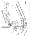
- the combustion chamber 1 has a external axial wall 2, as well as an axial wall internal 4, these two walls 2 and 4 being arranged coaxially along a longitudinal main axis 6 of the chamber 1, this axis 6 also corresponding to the axis longitudinal main of the turbomachine.
- Axial walls 2 and 4 are connected between them through a chamber bottom 8, which in the preferred embodiment describes, has a pilot head 10 and a takeoff head 12. As can be seen in the figure, the head take off 12 is shifted axially downstream and radially outward from the head 10.
- these heads 10 and 12, connected to each other through a wall between the head 19, are respectively provided with a deflector 14 and a deflector 16.
- this chamber bottom 8 could also present any other designs known to those skilled in the art, such as a design in which it does not include a deflector, without depart from the scope of the invention.
- Each of these injection ports 18 is designed so that it can cooperate with a fuel injector 20, in order to allow the combustion reactions inside this chamber 1 (the injection ports 18 of the deflectors 14 and 16 being staggered, only an injection port 18 and an injector 20 of the head takeoff 12 are shown on the half-cut view axial of Figure 1).
- these injectors 20 are also designed to allow the introduction of at least a portion of the air for combustion, it occurs in a primary zone 22 located in an upstream part of the combustion chamber 1.
- the air intended for combustion may also be introduced inside chamber 1 through of primary orifices 24, located all around the walls axial external 2 and internal 4.
- the primary orifices 24 are arranged upstream of a plurality of dilution orifices 26, the latter also being placed all around axial walls external 2 and internal 4, and having for main function to allow air supply a dilution zone 28 located downstream of the zone primary 24.
- the deflector 14 of the head pilot 10 has a passage 34 allowing the introduction of a part of the air flow of cooling D inside the chamber of combustion 1, close to the inner axial wall 4.
- passage 34 allows then initiation of a cooling air film D1 along the warm inner surface 32 of the internal axial wall 4.
- the deflector 16 of the takeoff head 12 has a passage 36 allowing the introduction of another part of the airflow of cooling D inside the chamber of combustion 1, close to the outer axial wall 2.
- the passage 36 allows therefore the initiation of an air film of D2 cooling along the inner surface hot 30 of the outer axial wall 2.
- the outer axial walls 2 and internal 4 are each of the multiperforated type on substantially all their length.
- these walls 2 and 4 present a multitude of perforations 38, preferably each cylindrical of circular section, and of diameter between about 0.3 and 0.6 mm.
- perforations 38 are distributed all around the wall concerned, and substantially all along this same axial wall. So, it is actually possible to get an air injection distributed over the entire axial wall surface, both from the point of view circumferential only longitudinal.
- the inner axial wall 4 has of a first zone 40 of perforations 38.
- This first zone 40 consisting of rows circumferential perforations 38 located the most upstream of the wall 4, is designed so that the cooling air is introduced against the current inside the cooling chamber 1, to enrich the cooling air film D1 from the chamber bottom 8.
- each perforation 38 of the first zone 40 in axial half-section such that represented in the single figure, the value of the angle A2 formed between a tangential local direction 42 of the inner axial wall 4 in this half-section, and a main direction 44 of the perforation 38 in this same half-section is between about 30 ° and 45 °.
- each perforation 38 can be defined as making an angle, with the inner axial wall 4, between about 30 ° and 45 °.
- the first zone 40 consists of a number of circumferential rows of perforations 38 included between one and ten, these rows corresponding to first rows upstream of the inner axial wall 4.
- each perforation 38 is practiced so that in half section axial, the value of the angle A4 formed between a tangential local direction 48 of the axial wall internal 4 in this half-section, and a direction main 50 of the perforation 38 in this same half-section, is between about 20 ° and 90 °.
- each perforation 38 can be defined as making an angle, with the internal axial wall 4, between about 20 ° and 90 °.
- the second zone 46 which is in the form of a plurality of circumferential rows of perforations 38, extends substantially to a downstream end of the inner wall 4.
- first and second zones 42 and 46 of the inner axial wall 4 are separated by a transitional zone 52 of perforations 38, these being made in such a way as to what their inclinations allow to pass gradually, from upstream to downstream, a flow of air from countercurrent cooling to a flow of air from co-current cooling.
- the transition zone 52 consists of a number of circumferential rows of perforations 38 included between one and three.
- the inclination of the perforations 38 of this zone of transition 52 could then vary gradually, from upstream to downstream, from -30 ° to 30 °.
- the outer axial wall 2 has of a first zone 54 of perforations 38.
- This first zone 54 consisting of rows circumferential perforations 38 located the most upstream of the wall 2, is designed so that the cooling air is introduced against the current inside the cooling chamber 1, to enrich the cooling air film D2 from the chamber bottom 8.
- the value of the angle A1 formed between a tangential local direction 56 of the outer axial wall 2 in this half-section, and a main direction 58 of the perforation 38 in this same half-section is between about 30 ° and 45 °.
- the first zone 54 consists of a number of circumferential rows of perforations 38 included between one and ten, these rows also corresponding in the first upstream rows of the outer axial wall 2.
- each perforation 38 is practiced so that in half section axial, the value of the angle A3 formed between a tangential local direction 62 of the axial wall external 2 in this half-section, and a direction main 64 of the perforation 38 in this same half-section, is between about 20 ° and 90 °.
- the second zone 60 which is in the form of a plurality of circumferential rows of perforations 38, extends substantially to a downstream end of the inner wall 4.
- first and second zones 54 and 60 of the outer axial wall 2 are also separated by a transitional zone 66 of perforations 38, these being made in such a way as to what their inclinations allow to pass gradually, from upstream to downstream, a flow of air from countercurrent cooling to a flow of air from co-current cooling.
- the transition zone 66 consists of a number of circumferential rows of perforations 38 included between one and three.
- the inclination of the perforations 38 of this zone of transition 66 could then vary gradually, from upstream to downstream, from -30 ° to 30 °.
- tangential local direction can correspond to a substantially parallel line to the two portions of straight lines symbolizing the wall in the axial half-section, near the perforation concerned.
- the term "direction" "perforation” may correspond to a line substantially parallel to the two segments of straight lines symbolizing the perforation concerned, always in this same axial half-section.
- the main directions of perforations 38 respectively correspond to their main axes, in the case where these perforations 38 are traversed diametrically by the section plane.
- a local area 70 perforations 38 is practiced downstream of each primary orifices 24 and dilution orifices 26. These local areas 70 are provided so that the cooling air is introduced locally against the current inside the chamber of In this way, the perforations 38 of these local areas 70 are practiced substantially from the same way as the one explained above for the perforations 38 of the first zones 40 and 54.
- the local areas 70 do not extend all around the axial walls 2 and 4, but only over a circumferential length restraint.
- local areas 70 are not necessarily followed, downstream, by transitional zones allowing to gradually correct the direction introduction of cooling air to inside the combustion chamber 1.
- each local area 70 of perforations 38 extends circumferentially over a length between one to two times the diameter of the primary orifice 24 or the dilution orifice 26 downstream of which lies, and that each of these local areas 70 has a number of rows of perforations 38 between one and five.
- the deflector 14 of the pilot head 10 has a passage 72 allowing the introduction of a part of the cooling air flow D to inside the combustion chamber 1, nearby the wall between the head 19.
- passage 72 allows then initiation of a cooling air film D3 along the warm inner surface 74 of the wall between the head 19, the latter extending mainly axially.
- this wall between head 19 is also of the type multi-perforated.
- the wall between-head 19 has, from upstream to downstream, a first zone 76 perforations 38 practiced so that the cooling air is introduced against the current inside the combustion chamber 1, a transient zone 78 of perforations 38, and a second zone 80 perforations 38 practiced so that cooling air is introduced to co-current inside the combustion chamber 1.
Landscapes
- Engineering & Computer Science (AREA)
- Chemical & Material Sciences (AREA)
- Combustion & Propulsion (AREA)
- Mechanical Engineering (AREA)
- General Engineering & Computer Science (AREA)
- Turbine Rotor Nozzle Sealing (AREA)
- Gas Burners (AREA)
- Combustion Of Fluid Fuel (AREA)
Abstract
Description
Claims (10)
- Chambre de combustion annulaire (1) de turbomachine, ladite chambre (1) comprenant une paroi axiale externe (2), une paroi axiale interne (4) et un fond de chambre (8) reliant lesdites parois axiales (2,4), le fond de chambre (8) étant pourvu d'une part d'une pluralité d'orifices d'injection (18) destinés à permettre au moins l'injection du carburant à l'intérieur de la chambre de combustion (1), et d'autre part de passages (34,36,72) permettant au moins l'initiation d'un film d'air de refroidissement (D2) le long de la surface intérieure chaude (30) de la paroi axiale externe (2) ainsi que celle d'un film d'air de refroidissement (D1) le long de la surface intérieure chaude (32) de la paroi axiale interne (4), lesdites parois axiales externe (2) et interne (4) étant multiperforées sur sensiblement toute leur longueur afin d'autoriser le renforcement des films d'air de refroidissement (D1,D2), caractérisée en ce que chacune desdites parois axiales externe (2) et interne (4) est munie, dans une partie amont, d'une première zone (54,40) de perforations (38) pratiquées de façon à ce que de l'air de refroidissement soit introduit à contre-courant à l'intérieur de la chambre de combustion (1).
- Chambre de combustion annulaire (1) selon la revendication 1, caractérisée en ce que chaque perforation (38) de la première zone (54) de la paroi axiale externe (2) est pratiquée de façon à ce qu'en demi-section axiale, la valeur de l'angle (A1) formé entre une direction locale tangentielle (56) de la paroi axiale externe (2) dans cette demi-section, et une direction principale (58) de la perforation (38) dans cette même demi-section, est comprise entre environ 30° et 45°, et en ce que chaque perforation (38) de la première zone (40) de la paroi axiale interne (4) est pratiquée de façon à ce qu'en demi-section axiale, la valeur de l'angle (A2) formé entre une direction locale tangentielle (42) de la paroi axiale interne (4) dans cette demi-section, et une direction principale (44) de la perforation (38) dans cette même demi-section, est comprise entre environ 30° et 45°.
- Chambre de combustion annulaire (1) selon la revendication 1 ou la revendication 2, caractérisée en ce que la première zone (54,40) de perforations (38) de chacune desdites parois axiales externe (2) et interne (4) comporte un nombre de rangées circonférentielles compris entre un et dix.
- Chambre de combustion annulaire (1) selon l'une quelconque des revendications précédentes, caractérisée en ce que chacune desdites parois axiales externe (2) et interne (4) est munie, en aval de la première zone (54,40) de perforations (38), d'une seconde zone (60,46) de perforations (38) pratiquées de façon à ce que de l'air de refroidissement soit introduit à co-courant à l'intérieur de la chambre de combustion (1).
- Chambre de combustion annulaire (1) selon la revendication 4, caractérisée en ce que chaque perforation (38) de la seconde zone (60) de la paroi axiale externe (2) est pratiquée de façon à ce qu'en demi-section axiale, la valeur de l'angle (A3) formé entre une direction locale tangentielle (62) de la paroi axiale externe (2) dans cette demi-section, et une direction principale (64) de la perforation (38) dans cette même demi-section, est comprise entre environ 20° et 90°, et en ce que chaque perforation (38) de la seconde zone (46) de la paroi axiale interne (4) est pratiquée de façon à ce qu'en demi-section axiale, la valeur de l'angle (A4) formé entre une direction locale tangentielle (48) de la paroi axiale interne (2) dans cette demi-section, et une direction principale (50) de la perforation (38) dans cette même demi-section, est comprise entre environ 20° et 90°.
- Chambre de combustion annulaire (1) selon la revendication 5, caractérisée en ce que chacune desdites parois axiales externe (2) et interne (4) est munie, entre la première zone (54,40) et la seconde zone (60,46) de perforations (38), d'une zone transitoire (66,52) de perforations (38).
- Chambre de combustion annulaire (1) selon la revendication 6, caractérisée en ce que la zone transitoire (66,52) de perforations (38) de chacune desdites parois axiales externe (2) et interne (4) comporte un nombre de rangées circonférentielles compris entre un et trois.
- Chambre de combustion annulaire (1) selon l'une quelconque des revendications précédentes, caractérisée en ce que le fond de chambre (8) comprend une paroi entre-tête (19) disposant, d'amont en aval, d'une première zone (76) de perforations (38) pratiquées de façon à ce que de l'air de refroidissement soit introduit à contre-courant à l'intérieur de la chambre de combustion (1), d'une zone transitoire (78) de perforations (38), et d'une seconde zone (80) de perforations (38) pratiquées de façon à ce que de l'air de refroidissement soit introduit à co-courant à l'intérieur de la chambre de combustion (1).
- Chambre de combustion annulaire (1) selon l'une quelconque des revendications précédentes, caractérisée en ce que les parois axiales externe (2) et interne (4) comportent chacune une pluralité d'orifices primaires (24) et d'orifices de dilution (26), une zone locale (70) de perforations (38) pratiquées de façon à ce que de l'air de refroidissement soit introduit de façon locale à contre-courant à l'intérieur de la chambre de combustion (1) étant prévue en aval de chacun desdits orifices primaires (24), ainsi qu'en aval de chacun desdits orifices de dilution (26).
- Chambre de combustion annulaire (1) selon la revendication 9, caractérisée en ce que chaque zone locale (70) de perforations (38) s'étend circonférentiellement sur une longueur comprise entre une à deux fois le diamètre de l'orifice primaire (24) ou de l'orifice de dilution (26) en aval duquel elle se trouve.
Applications Claiming Priority (2)
| Application Number | Priority Date | Filing Date | Title |
|---|---|---|---|
| FR0350226A FR2856468B1 (fr) | 2003-06-17 | 2003-06-17 | Chambre de combustion annulaire de turbomachine |
| FR0350226 | 2003-06-17 |
Publications (2)
| Publication Number | Publication Date |
|---|---|
| EP1489359A1 true EP1489359A1 (fr) | 2004-12-22 |
| EP1489359B1 EP1489359B1 (fr) | 2006-05-03 |
Family
ID=33396880
Family Applications (1)
| Application Number | Title | Priority Date | Filing Date |
|---|---|---|---|
| EP04102723A Expired - Lifetime EP1489359B1 (fr) | 2003-06-17 | 2004-06-15 | Chambre de combustion annulaire de turbomachine |
Country Status (7)
| Country | Link |
|---|---|
| US (1) | US7155913B2 (fr) |
| EP (1) | EP1489359B1 (fr) |
| CA (1) | CA2470928C (fr) |
| DE (1) | DE602004000789T2 (fr) |
| ES (1) | ES2262094T3 (fr) |
| FR (1) | FR2856468B1 (fr) |
| RU (1) | RU2342602C2 (fr) |
Cited By (1)
| Publication number | Priority date | Publication date | Assignee | Title |
|---|---|---|---|---|
| FR2974162A1 (fr) * | 2011-04-14 | 2012-10-19 | Snecma | Virole de tube a flamme dans une chambre de combustion de turbomachine |
Families Citing this family (16)
| Publication number | Priority date | Publication date | Assignee | Title |
|---|---|---|---|---|
| US7506511B2 (en) * | 2003-12-23 | 2009-03-24 | Honeywell International Inc. | Reduced exhaust emissions gas turbine engine combustor |
| US7954326B2 (en) * | 2007-11-28 | 2011-06-07 | Honeywell International Inc. | Systems and methods for cooling gas turbine engine transition liners |
| GB2460403B (en) * | 2008-05-28 | 2010-11-17 | Rolls Royce Plc | Combustor Wall with Improved Cooling |
| US7874157B2 (en) * | 2008-06-05 | 2011-01-25 | General Electric Company | Coanda pilot nozzle for low emission combustors |
| US8220269B2 (en) * | 2008-09-30 | 2012-07-17 | Alstom Technology Ltd. | Combustor for a gas turbine engine with effusion cooled baffle |
| FR2979416B1 (fr) * | 2011-08-26 | 2013-09-20 | Turbomeca | Paroi de chambre de combustion |
| US10260748B2 (en) | 2012-12-21 | 2019-04-16 | United Technologies Corporation | Gas turbine engine combustor with tailored temperature profile |
| EP2984317B1 (fr) * | 2013-04-12 | 2019-03-13 | United Technologies Corporation | Refroidissement de jonction en t de panneau de chambre de combustion |
| EP3044444B1 (fr) | 2013-09-13 | 2019-11-06 | United Technologies Corporation | Chambre de combustion pour une turbine à gaz avec un panneau de chemisage hermétiquement scellé |
| FR3011620B1 (fr) * | 2013-10-04 | 2018-03-09 | Snecma | Chambre de combustion de turbomachine pourvue d'un passage d'entree d'air ameliore en aval d'un orifice de passage de bougie |
| EP3060852B1 (fr) | 2013-10-24 | 2023-07-05 | Raytheon Technologies Corporation | Chambre de combustion pour moteur de turbine à gaz avec agencement de jet de trempe |
| RU2581267C2 (ru) * | 2013-11-12 | 2016-04-20 | Федеральное государственное бюджетное научное учреждение "Всероссийский научно-исследовательский институт электрификации сельского хозяйства" (ФГБНУ ВИЭСХ) | Устройство камеры сгорания с регулируемым завихрителем для микро газотурбинного двигателя, где турбиной и компрессором является турбокомпрессор от двс |
| EP3077728B8 (fr) | 2013-12-06 | 2021-03-31 | Raytheon Technologies Corporation | Chambre de combustion de moteur à turbine à gaz ayant des passages d'effusion avec orientation de co-tourbillonnement, et procédé |
| US10344979B2 (en) | 2014-01-30 | 2019-07-09 | United Technologies Corporation | Cooling flow for leading panel in a gas turbine engine combustor |
| CN109578141B (zh) * | 2019-01-23 | 2023-10-20 | 中国船舶重工集团公司第七0三研究所 | 一种可倒车燃气轮机动力涡轮的排气涡壳 |
| CN115183273A (zh) * | 2022-07-21 | 2022-10-14 | 中国航发沈阳发动机研究所 | 一种加力发动机燃烧室 |
Citations (9)
| Publication number | Priority date | Publication date | Assignee | Title |
|---|---|---|---|---|
| US2974485A (en) * | 1958-06-02 | 1961-03-14 | Gen Electric | Combustor for fluid fuels |
| US3751911A (en) * | 1970-04-18 | 1973-08-14 | Motoren Turbinen Union | Air inlet arrangement for gas turbine engine combustion chamber |
| GB2021204A (en) * | 1978-05-20 | 1979-11-28 | Rolls Royce | Gas Turbine Combustion Chamber |
| GB2073396A (en) * | 1980-03-29 | 1981-10-14 | Rolls Royce | Gas turbine combustion chambers |
| GB2099978A (en) * | 1981-05-11 | 1982-12-15 | Rolls Royce | Gas turbine engine combustor |
| US5142871A (en) * | 1991-01-22 | 1992-09-01 | General Electric Company | Combustor dome plate support having uniform thickness arcuate apex with circumferentially spaced coolant apertures |
| US5331805A (en) * | 1993-04-22 | 1994-07-26 | Alliedsignal Inc. | Reduced diameter annular combustor |
| US5775108A (en) * | 1995-04-26 | 1998-07-07 | Societe Nationale D'etude Et De Construction De Moteurs D'aviation "Snecma" | Combustion chamber having a multi-hole cooling system with variably oriented holes |
| EP1010944A2 (fr) * | 1998-12-18 | 2000-06-21 | General Electric Company | Dispositf de refroidissement et de connexion pour la chemise d'une chambre de combustion pour une turbine à gaz |
Family Cites Families (31)
| Publication number | Priority date | Publication date | Assignee | Title |
|---|---|---|---|---|
| GB1492049A (en) * | 1974-12-07 | 1977-11-16 | Rolls Royce | Combustion equipment for gas turbine engines |
| FR2402068A1 (fr) * | 1977-09-02 | 1979-03-30 | Snecma | Chambre de combustion anti-pollution |
| US4194358A (en) * | 1977-12-15 | 1980-03-25 | General Electric Company | Double annular combustor configuration |
| US4244178A (en) * | 1978-03-20 | 1981-01-13 | General Motors Corporation | Porous laminated combustor structure |
| US4896510A (en) * | 1987-02-06 | 1990-01-30 | General Electric Company | Combustor liner cooling arrangement |
| US5197289A (en) * | 1990-11-26 | 1993-03-30 | General Electric Company | Double dome combustor |
| US5197278A (en) * | 1990-12-17 | 1993-03-30 | General Electric Company | Double dome combustor and method of operation |
| US5220795A (en) * | 1991-04-16 | 1993-06-22 | General Electric Company | Method and apparatus for injecting dilution air |
| CA2070518C (fr) * | 1991-07-01 | 2001-10-02 | Adrian Mark Ablett | Ensemble dome pour chambre de combustion |
| US5154060A (en) * | 1991-08-12 | 1992-10-13 | General Electric Company | Stiffened double dome combustor |
| US5289687A (en) * | 1992-03-30 | 1994-03-01 | General Electric Company | One-piece cowl for a double annular combustor |
| CA2089285C (fr) * | 1992-03-30 | 2002-06-25 | Stephen Winthrop Falls | Noyau central segmente pour chambre de combustion annulaire double |
| US5321951A (en) * | 1992-03-30 | 1994-06-21 | General Electric Company | Integral combustor splash plate and sleeve |
| CA2089302C (fr) * | 1992-03-30 | 2004-07-06 | Joseph Frank Savelli | Chambre de combustion annulaire double |
| JP2597800B2 (ja) * | 1992-06-12 | 1997-04-09 | ゼネラル・エレクトリック・カンパニイ | ガスタービンエンジン用燃焼器 |
| FR2706021B1 (fr) * | 1993-06-03 | 1995-07-07 | Snecma | Chambre de combustion comprenant un ensemble séparateur de gaz. |
| FR2712379B1 (fr) * | 1993-11-10 | 1995-12-29 | Snecma | Chambre de combustion pour turbomachine munie d'un séparateur des gaz. |
| US5421158A (en) * | 1994-10-21 | 1995-06-06 | General Electric Company | Segmented centerbody for a double annular combustor |
| US5623827A (en) * | 1995-01-26 | 1997-04-29 | General Electric Company | Regenerative cooled dome assembly for a gas turbine engine combustor |
| WO1996027766A1 (fr) * | 1995-03-08 | 1996-09-12 | Bmw Rolls-Royce Gmbh | Chambre de combustion a anneau double et etagement axial pour une turbine a gaz |
| US5970716A (en) * | 1997-10-02 | 1999-10-26 | General Electric Company | Apparatus for retaining centerbody between adjacent domes of multiple annular combustor employing interference and clamping fits |
| US5974805A (en) * | 1997-10-28 | 1999-11-02 | Rolls-Royce Plc | Heat shielding for a turbine combustor |
| FR2777634B1 (fr) * | 1998-04-16 | 2000-05-19 | Snecma | Separateur pour chambre de combustion a deux tetes |
| US6079199A (en) * | 1998-06-03 | 2000-06-27 | Pratt & Whitney Canada Inc. | Double pass air impingement and air film cooling for gas turbine combustor walls |
| US6155056A (en) * | 1998-06-04 | 2000-12-05 | Pratt & Whitney Canada Corp. | Cooling louver for annular gas turbine engine combustion chamber |
| US6474070B1 (en) * | 1998-06-10 | 2002-11-05 | General Electric Company | Rich double dome combustor |
| US6145319A (en) * | 1998-07-16 | 2000-11-14 | General Electric Company | Transitional multihole combustion liner |
| US6260359B1 (en) * | 1999-11-01 | 2001-07-17 | General Electric Company | Offset dilution combustor liner |
| US6279323B1 (en) * | 1999-11-01 | 2001-08-28 | General Electric Company | Low emissions combustor |
| US6655146B2 (en) * | 2001-07-31 | 2003-12-02 | General Electric Company | Hybrid film cooled combustor liner |
| US6513331B1 (en) * | 2001-08-21 | 2003-02-04 | General Electric Company | Preferential multihole combustor liner |
-
2003
- 2003-06-17 FR FR0350226A patent/FR2856468B1/fr not_active Expired - Fee Related
-
2004
- 2004-06-15 EP EP04102723A patent/EP1489359B1/fr not_active Expired - Lifetime
- 2004-06-15 DE DE602004000789T patent/DE602004000789T2/de not_active Expired - Lifetime
- 2004-06-15 US US10/866,695 patent/US7155913B2/en not_active Expired - Lifetime
- 2004-06-15 ES ES04102723T patent/ES2262094T3/es not_active Expired - Lifetime
- 2004-06-15 CA CA2470928A patent/CA2470928C/fr not_active Expired - Lifetime
- 2004-06-16 RU RU2004118309/06A patent/RU2342602C2/ru active
Patent Citations (9)
| Publication number | Priority date | Publication date | Assignee | Title |
|---|---|---|---|---|
| US2974485A (en) * | 1958-06-02 | 1961-03-14 | Gen Electric | Combustor for fluid fuels |
| US3751911A (en) * | 1970-04-18 | 1973-08-14 | Motoren Turbinen Union | Air inlet arrangement for gas turbine engine combustion chamber |
| GB2021204A (en) * | 1978-05-20 | 1979-11-28 | Rolls Royce | Gas Turbine Combustion Chamber |
| GB2073396A (en) * | 1980-03-29 | 1981-10-14 | Rolls Royce | Gas turbine combustion chambers |
| GB2099978A (en) * | 1981-05-11 | 1982-12-15 | Rolls Royce | Gas turbine engine combustor |
| US5142871A (en) * | 1991-01-22 | 1992-09-01 | General Electric Company | Combustor dome plate support having uniform thickness arcuate apex with circumferentially spaced coolant apertures |
| US5331805A (en) * | 1993-04-22 | 1994-07-26 | Alliedsignal Inc. | Reduced diameter annular combustor |
| US5775108A (en) * | 1995-04-26 | 1998-07-07 | Societe Nationale D'etude Et De Construction De Moteurs D'aviation "Snecma" | Combustion chamber having a multi-hole cooling system with variably oriented holes |
| EP1010944A2 (fr) * | 1998-12-18 | 2000-06-21 | General Electric Company | Dispositf de refroidissement et de connexion pour la chemise d'une chambre de combustion pour une turbine à gaz |
Cited By (1)
| Publication number | Priority date | Publication date | Assignee | Title |
|---|---|---|---|---|
| FR2974162A1 (fr) * | 2011-04-14 | 2012-10-19 | Snecma | Virole de tube a flamme dans une chambre de combustion de turbomachine |
Also Published As
| Publication number | Publication date |
|---|---|
| ES2262094T3 (es) | 2006-11-16 |
| DE602004000789D1 (de) | 2006-06-08 |
| US20050042076A1 (en) | 2005-02-24 |
| FR2856468A1 (fr) | 2004-12-24 |
| FR2856468B1 (fr) | 2007-11-23 |
| US7155913B2 (en) | 2007-01-02 |
| RU2342602C2 (ru) | 2008-12-27 |
| CA2470928A1 (fr) | 2004-12-17 |
| DE602004000789T2 (de) | 2007-05-31 |
| CA2470928C (fr) | 2011-11-15 |
| EP1489359B1 (fr) | 2006-05-03 |
| RU2004118309A (ru) | 2006-01-10 |
Similar Documents
| Publication | Publication Date | Title |
|---|---|---|
| EP1489359B1 (fr) | Chambre de combustion annulaire de turbomachine | |
| EP3267111B1 (fr) | Paroi annulaire de chambre de combustion à refroidissement amelioré au niveau des trous primaires et/ou de dilution | |
| EP1634021B1 (fr) | Chambre de combustion annulaire de turbomachine | |
| FR2968030A1 (fr) | Turbine basse-pression de turbomachine d'aeronef, comprenant un distributeur sectorise de conception amelioree | |
| EP2678610B1 (fr) | Chambre annulaire de combustion de turbomachine comprenant des orifices de dilution ameliores | |
| EP0248731A1 (fr) | Chambre de combustion pour turbomachines à orifices de mélange assurant le positionnement de la paroi chaude sur la paroi froide | |
| EP1777458A1 (fr) | Amélioration des performances d'une chambre de combustion par multiperforation des parois | |
| EP2042806A1 (fr) | Chambre de combustion d'une turbomachine | |
| FR2996289A1 (fr) | Chambre de combustion comprenant un tube a flamme fixe au moyen de trois elements de centrage. | |
| CA2987526A1 (fr) | Paroi annulaire de chambre de combustion a refroidissement optimise | |
| WO2012120230A1 (fr) | Injecteur pour le mélange de deux ergols comprenant au moins un élément d'injection a structure tricoaxiale | |
| FR3080406A1 (fr) | Distributeur de turbine ameliore pour turbomachine | |
| EP1855011A1 (fr) | Ensemble pour compresseur de moteur d'aéronef comprenant des aubes à attache marteau à pied incline | |
| CA2898864A1 (fr) | Aubage fixe de distribution de flux dans une turbomachine, comprenant une plate-forme interne a renforts integres, turbomachine et procede de fabrication associes | |
| FR3096722A1 (fr) | Joint d’étanchéité dynamique pour turbomachine comprenant une pièce abradable multicouche | |
| FR3055950B1 (fr) | Chambre de combustion pour turbomachine comprenant des moyens pour ameliorer le refroidissement d'une paroi annulaire dans le sillage d'un obstacle | |
| FR3096114A1 (fr) | Chambre de combustion comprenant des moyens de refroidissement d’une zone d’enveloppe annulaire en aval d’une cheminée | |
| EP4179256B1 (fr) | Chambre annulaire de combustion pour une turbomachine d'aéronef | |
| EP4240958A1 (fr) | Fixation d'un cône d'éjection dans une turbine de turbomachine | |
| WO2021069808A1 (fr) | Canne de prevaporisation pour une chambre de combustion de turbomachine | |
| FR3098569A1 (fr) | Paroi annulaire pour chambre de combustion de turbomachine comprenant des trous primaires, des trous de dilution et des orifices de refroidissement inclines | |
| FR3116857A1 (fr) | composant de turbomachine comprenant une paroi pourvue de moyens de refroidissement | |
| FR3115833A1 (fr) | Fixation d’un cône d’éjection dans une turbine de turbomachine | |
| FR2999277A1 (fr) | Paroi annulaire de chambre de combustion en aval d'un compresseur centrifuge | |
| EP3262348B1 (fr) | Chambre de combustion de turbomachine comportant une pièce pénétrante avec ouverture |
Legal Events
| Date | Code | Title | Description |
|---|---|---|---|
| PUAI | Public reference made under article 153(3) epc to a published international application that has entered the european phase |
Free format text: ORIGINAL CODE: 0009012 |
|
| AK | Designated contracting states |
Kind code of ref document: A1 Designated state(s): AT BE BG CH CY CZ DE DK EE ES FI FR GB GR HU IE IT LI LU MC NL PL PT RO SE SI SK TR |
|
| AX | Request for extension of the european patent |
Extension state: AL HR LT LV MK |
|
| 17P | Request for examination filed |
Effective date: 20050606 |
|
| AKX | Designation fees paid |
Designated state(s): DE ES FR GB IT SE |
|
| RAP1 | Party data changed (applicant data changed or rights of an application transferred) |
Owner name: SNECMA |
|
| GRAP | Despatch of communication of intention to grant a patent |
Free format text: ORIGINAL CODE: EPIDOSNIGR1 |
|
| GRAS | Grant fee paid |
Free format text: ORIGINAL CODE: EPIDOSNIGR3 |
|
| GRAA | (expected) grant |
Free format text: ORIGINAL CODE: 0009210 |
|
| AK | Designated contracting states |
Kind code of ref document: B1 Designated state(s): DE ES FR GB IT SE |
|
| REG | Reference to a national code |
Ref country code: GB Ref legal event code: FG4D Free format text: NOT ENGLISH |
|
| REF | Corresponds to: |
Ref document number: 602004000789 Country of ref document: DE Date of ref document: 20060608 Kind code of ref document: P |
|
| GBT | Gb: translation of ep patent filed (gb section 77(6)(a)/1977) |
Effective date: 20060607 |
|
| REG | Reference to a national code |
Ref country code: SE Ref legal event code: TRGR |
|
| REG | Reference to a national code |
Ref country code: ES Ref legal event code: FG2A Ref document number: 2262094 Country of ref document: ES Kind code of ref document: T3 |
|
| PLBE | No opposition filed within time limit |
Free format text: ORIGINAL CODE: 0009261 |
|
| STAA | Information on the status of an ep patent application or granted ep patent |
Free format text: STATUS: NO OPPOSITION FILED WITHIN TIME LIMIT |
|
| 26N | No opposition filed |
Effective date: 20070206 |
|
| PGFP | Annual fee paid to national office [announced via postgrant information from national office to epo] |
Ref country code: SE Payment date: 20070528 Year of fee payment: 4 |
|
| PGFP | Annual fee paid to national office [announced via postgrant information from national office to epo] |
Ref country code: ES Payment date: 20070607 Year of fee payment: 4 |
|
| EUG | Se: european patent has lapsed | ||
| REG | Reference to a national code |
Ref country code: ES Ref legal event code: FD2A Effective date: 20080616 |
|
| PG25 | Lapsed in a contracting state [announced via postgrant information from national office to epo] |
Ref country code: ES Free format text: LAPSE BECAUSE OF NON-PAYMENT OF DUE FEES Effective date: 20080616 |
|
| PG25 | Lapsed in a contracting state [announced via postgrant information from national office to epo] |
Ref country code: SE Free format text: LAPSE BECAUSE OF NON-PAYMENT OF DUE FEES Effective date: 20080616 |
|
| REG | Reference to a national code |
Ref country code: FR Ref legal event code: PLFP Year of fee payment: 13 |
|
| REG | Reference to a national code |
Ref country code: FR Ref legal event code: PLFP Year of fee payment: 14 |
|
| REG | Reference to a national code |
Ref country code: FR Ref legal event code: CD Owner name: SAFRAN AIRCRAFT ENGINES Effective date: 20170717 |
|
| REG | Reference to a national code |
Ref country code: FR Ref legal event code: PLFP Year of fee payment: 15 |
|
| PGFP | Annual fee paid to national office [announced via postgrant information from national office to epo] |
Ref country code: IT Payment date: 20230523 Year of fee payment: 20 Ref country code: FR Payment date: 20230523 Year of fee payment: 20 Ref country code: DE Payment date: 20230523 Year of fee payment: 20 |
|
| PGFP | Annual fee paid to national office [announced via postgrant information from national office to epo] |
Ref country code: GB Payment date: 20230523 Year of fee payment: 20 |
|
| REG | Reference to a national code |
Ref country code: DE Ref legal event code: R071 Ref document number: 602004000789 Country of ref document: DE |
|
| PG25 | Lapsed in a contracting state [announced via postgrant information from national office to epo] |
Ref country code: GB Free format text: LAPSE BECAUSE OF EXPIRATION OF PROTECTION Effective date: 20240614 |
|
| PG25 | Lapsed in a contracting state [announced via postgrant information from national office to epo] |
Ref country code: GB Free format text: LAPSE BECAUSE OF EXPIRATION OF PROTECTION Effective date: 20240614 |