EP3044444B1 - Chambre de combustion pour une turbine à gaz avec un panneau de chemisage hermétiquement scellé - Google Patents
Chambre de combustion pour une turbine à gaz avec un panneau de chemisage hermétiquement scellé Download PDFInfo
- Publication number
- EP3044444B1 EP3044444B1 EP14843958.1A EP14843958A EP3044444B1 EP 3044444 B1 EP3044444 B1 EP 3044444B1 EP 14843958 A EP14843958 A EP 14843958A EP 3044444 B1 EP3044444 B1 EP 3044444B1
- Authority
- EP
- European Patent Office
- Prior art keywords
- combustor
- seal
- liner panel
- shell
- pressure drop
- Prior art date
- Legal status (The legal status is an assumption and is not a legal conclusion. Google has not performed a legal analysis and makes no representation as to the accuracy of the status listed.)
- Active
Links
- 238000001816 cooling Methods 0.000 claims description 14
- 238000000034 method Methods 0.000 claims description 5
- 238000007789 sealing Methods 0.000 claims description 3
- 239000007789 gas Substances 0.000 description 17
- 238000002485 combustion reaction Methods 0.000 description 9
- 239000000446 fuel Substances 0.000 description 9
- 239000000567 combustion gas Substances 0.000 description 5
- 230000000712 assembly Effects 0.000 description 4
- 238000000429 assembly Methods 0.000 description 4
- 230000007423 decrease Effects 0.000 description 3
- 230000003068 static effect Effects 0.000 description 3
- PXHVJJICTQNCMI-UHFFFAOYSA-N Nickel Chemical compound [Ni] PXHVJJICTQNCMI-UHFFFAOYSA-N 0.000 description 2
- 230000005540 biological transmission Effects 0.000 description 2
- 230000015572 biosynthetic process Effects 0.000 description 2
- 238000010790 dilution Methods 0.000 description 2
- 239000012895 dilution Substances 0.000 description 2
- 239000004215 Carbon black (E152) Substances 0.000 description 1
- 229910000990 Ni alloy Inorganic materials 0.000 description 1
- 239000000956 alloy Substances 0.000 description 1
- 239000000919 ceramic Substances 0.000 description 1
- 238000006243 chemical reaction Methods 0.000 description 1
- 238000004891 communication Methods 0.000 description 1
- 230000006835 compression Effects 0.000 description 1
- 238000007906 compression Methods 0.000 description 1
- 238000012937 correction Methods 0.000 description 1
- 230000001419 dependent effect Effects 0.000 description 1
- 238000011161 development Methods 0.000 description 1
- 229930195733 hydrocarbon Natural products 0.000 description 1
- 150000002430 hydrocarbons Chemical class 0.000 description 1
- 238000002347 injection Methods 0.000 description 1
- 239000007924 injection Substances 0.000 description 1
- 239000000463 material Substances 0.000 description 1
- 238000005259 measurement Methods 0.000 description 1
- 239000000203 mixture Substances 0.000 description 1
- 238000012986 modification Methods 0.000 description 1
- 230000004048 modification Effects 0.000 description 1
- 239000003607 modifier Substances 0.000 description 1
- 229910052759 nickel Inorganic materials 0.000 description 1
- 238000010791 quenching Methods 0.000 description 1
- 230000005855 radiation Effects 0.000 description 1
- 229910000601 superalloy Inorganic materials 0.000 description 1
- 238000012360 testing method Methods 0.000 description 1
- 238000012546 transfer Methods 0.000 description 1
Images


Classifications
-
- F—MECHANICAL ENGINEERING; LIGHTING; HEATING; WEAPONS; BLASTING
- F02—COMBUSTION ENGINES; HOT-GAS OR COMBUSTION-PRODUCT ENGINE PLANTS
- F02C—GAS-TURBINE PLANTS; AIR INTAKES FOR JET-PROPULSION PLANTS; CONTROLLING FUEL SUPPLY IN AIR-BREATHING JET-PROPULSION PLANTS
- F02C7/00—Features, components parts, details or accessories, not provided for in, or of interest apart form groups F02C1/00 - F02C6/00; Air intakes for jet-propulsion plants
- F02C7/24—Heat or noise insulation
-
- F—MECHANICAL ENGINEERING; LIGHTING; HEATING; WEAPONS; BLASTING
- F23—COMBUSTION APPARATUS; COMBUSTION PROCESSES
- F23R—GENERATING COMBUSTION PRODUCTS OF HIGH PRESSURE OR HIGH VELOCITY, e.g. GAS-TURBINE COMBUSTION CHAMBERS
- F23R3/00—Continuous combustion chambers using liquid or gaseous fuel
- F23R3/02—Continuous combustion chambers using liquid or gaseous fuel characterised by the air-flow or gas-flow configuration
- F23R3/04—Air inlet arrangements
- F23R3/06—Arrangement of apertures along the flame tube
-
- F—MECHANICAL ENGINEERING; LIGHTING; HEATING; WEAPONS; BLASTING
- F02—COMBUSTION ENGINES; HOT-GAS OR COMBUSTION-PRODUCT ENGINE PLANTS
- F02C—GAS-TURBINE PLANTS; AIR INTAKES FOR JET-PROPULSION PLANTS; CONTROLLING FUEL SUPPLY IN AIR-BREATHING JET-PROPULSION PLANTS
- F02C7/00—Features, components parts, details or accessories, not provided for in, or of interest apart form groups F02C1/00 - F02C6/00; Air intakes for jet-propulsion plants
- F02C7/12—Cooling of plants
- F02C7/16—Cooling of plants characterised by cooling medium
- F02C7/18—Cooling of plants characterised by cooling medium the medium being gaseous, e.g. air
-
- F—MECHANICAL ENGINEERING; LIGHTING; HEATING; WEAPONS; BLASTING
- F02—COMBUSTION ENGINES; HOT-GAS OR COMBUSTION-PRODUCT ENGINE PLANTS
- F02C—GAS-TURBINE PLANTS; AIR INTAKES FOR JET-PROPULSION PLANTS; CONTROLLING FUEL SUPPLY IN AIR-BREATHING JET-PROPULSION PLANTS
- F02C7/00—Features, components parts, details or accessories, not provided for in, or of interest apart form groups F02C1/00 - F02C6/00; Air intakes for jet-propulsion plants
- F02C7/28—Arrangement of seals
-
- F—MECHANICAL ENGINEERING; LIGHTING; HEATING; WEAPONS; BLASTING
- F23—COMBUSTION APPARATUS; COMBUSTION PROCESSES
- F23R—GENERATING COMBUSTION PRODUCTS OF HIGH PRESSURE OR HIGH VELOCITY, e.g. GAS-TURBINE COMBUSTION CHAMBERS
- F23R3/00—Continuous combustion chambers using liquid or gaseous fuel
- F23R3/002—Wall structures
-
- F—MECHANICAL ENGINEERING; LIGHTING; HEATING; WEAPONS; BLASTING
- F23—COMBUSTION APPARATUS; COMBUSTION PROCESSES
- F23R—GENERATING COMBUSTION PRODUCTS OF HIGH PRESSURE OR HIGH VELOCITY, e.g. GAS-TURBINE COMBUSTION CHAMBERS
- F23R3/00—Continuous combustion chambers using liquid or gaseous fuel
- F23R3/005—Combined with pressure or heat exchangers
-
- F—MECHANICAL ENGINEERING; LIGHTING; HEATING; WEAPONS; BLASTING
- F23—COMBUSTION APPARATUS; COMBUSTION PROCESSES
- F23R—GENERATING COMBUSTION PRODUCTS OF HIGH PRESSURE OR HIGH VELOCITY, e.g. GAS-TURBINE COMBUSTION CHAMBERS
- F23R3/00—Continuous combustion chambers using liquid or gaseous fuel
- F23R3/42—Continuous combustion chambers using liquid or gaseous fuel characterised by the arrangement or form of the flame tubes or combustion chambers
- F23R3/50—Combustion chambers comprising an annular flame tube within an annular casing
-
- F—MECHANICAL ENGINEERING; LIGHTING; HEATING; WEAPONS; BLASTING
- F23—COMBUSTION APPARATUS; COMBUSTION PROCESSES
- F23R—GENERATING COMBUSTION PRODUCTS OF HIGH PRESSURE OR HIGH VELOCITY, e.g. GAS-TURBINE COMBUSTION CHAMBERS
- F23R3/00—Continuous combustion chambers using liquid or gaseous fuel
- F23R3/42—Continuous combustion chambers using liquid or gaseous fuel characterised by the arrangement or form of the flame tubes or combustion chambers
- F23R3/60—Support structures; Attaching or mounting means
-
- F—MECHANICAL ENGINEERING; LIGHTING; HEATING; WEAPONS; BLASTING
- F23—COMBUSTION APPARATUS; COMBUSTION PROCESSES
- F23R—GENERATING COMBUSTION PRODUCTS OF HIGH PRESSURE OR HIGH VELOCITY, e.g. GAS-TURBINE COMBUSTION CHAMBERS
- F23R2900/00—Special features of, or arrangements for continuous combustion chambers; Combustion processes therefor
- F23R2900/00012—Details of sealing devices
-
- F—MECHANICAL ENGINEERING; LIGHTING; HEATING; WEAPONS; BLASTING
- F23—COMBUSTION APPARATUS; COMBUSTION PROCESSES
- F23R—GENERATING COMBUSTION PRODUCTS OF HIGH PRESSURE OR HIGH VELOCITY, e.g. GAS-TURBINE COMBUSTION CHAMBERS
- F23R2900/00—Special features of, or arrangements for continuous combustion chambers; Combustion processes therefor
- F23R2900/00017—Assembling combustion chamber liners or subparts
-
- F—MECHANICAL ENGINEERING; LIGHTING; HEATING; WEAPONS; BLASTING
- F23—COMBUSTION APPARATUS; COMBUSTION PROCESSES
- F23R—GENERATING COMBUSTION PRODUCTS OF HIGH PRESSURE OR HIGH VELOCITY, e.g. GAS-TURBINE COMBUSTION CHAMBERS
- F23R2900/00—Special features of, or arrangements for continuous combustion chambers; Combustion processes therefor
- F23R2900/03041—Effusion cooled combustion chamber walls or domes
-
- F—MECHANICAL ENGINEERING; LIGHTING; HEATING; WEAPONS; BLASTING
- F23—COMBUSTION APPARATUS; COMBUSTION PROCESSES
- F23R—GENERATING COMBUSTION PRODUCTS OF HIGH PRESSURE OR HIGH VELOCITY, e.g. GAS-TURBINE COMBUSTION CHAMBERS
- F23R2900/00—Special features of, or arrangements for continuous combustion chambers; Combustion processes therefor
- F23R2900/03042—Film cooled combustion chamber walls or domes
-
- F—MECHANICAL ENGINEERING; LIGHTING; HEATING; WEAPONS; BLASTING
- F23—COMBUSTION APPARATUS; COMBUSTION PROCESSES
- F23R—GENERATING COMBUSTION PRODUCTS OF HIGH PRESSURE OR HIGH VELOCITY, e.g. GAS-TURBINE COMBUSTION CHAMBERS
- F23R2900/00—Special features of, or arrangements for continuous combustion chambers; Combustion processes therefor
- F23R2900/03044—Impingement cooled combustion chamber walls or subassemblies
-
- F—MECHANICAL ENGINEERING; LIGHTING; HEATING; WEAPONS; BLASTING
- F23—COMBUSTION APPARATUS; COMBUSTION PROCESSES
- F23R—GENERATING COMBUSTION PRODUCTS OF HIGH PRESSURE OR HIGH VELOCITY, e.g. GAS-TURBINE COMBUSTION CHAMBERS
- F23R2900/00—Special features of, or arrangements for continuous combustion chambers; Combustion processes therefor
- F23R2900/03045—Convection cooled combustion chamber walls provided with turbolators or means for creating turbulences to increase cooling
-
- Y—GENERAL TAGGING OF NEW TECHNOLOGICAL DEVELOPMENTS; GENERAL TAGGING OF CROSS-SECTIONAL TECHNOLOGIES SPANNING OVER SEVERAL SECTIONS OF THE IPC; TECHNICAL SUBJECTS COVERED BY FORMER USPC CROSS-REFERENCE ART COLLECTIONS [XRACs] AND DIGESTS
- Y02—TECHNOLOGIES OR APPLICATIONS FOR MITIGATION OR ADAPTATION AGAINST CLIMATE CHANGE
- Y02T—CLIMATE CHANGE MITIGATION TECHNOLOGIES RELATED TO TRANSPORTATION
- Y02T50/00—Aeronautics or air transport
- Y02T50/60—Efficient propulsion technologies, e.g. for aircraft
Definitions
- the present disclosure relates to a gas turbine engine and, more particularly, to a combustor section therefor.
- Gas turbine engines such as those that power modern commercial and military aircraft, generally include a compressor section to pressurize an airflow, a combustor section to burn a hydrocarbon fuel in the presence of the pressurized air, and a turbine section to extract energy from the resultant combustion gases.
- Advanced engine cycles require the combustor section to operate at high compressor exit temperatures.
- a survey of typical flight envelopes often require that high compressor exit temperatures exist with reduced supply pressure at high altitude. These operational conditions may result in relatively high convection and radiation heat loads.
- Prior art includes DE 102005046731 , US 2007/0245742 , US 5758503 and EP 1378690 .
- a combustor of a gas turbine engine is claimed in claim 1.
- a method of cooling a wall assembly within a combustor of a gas turbine engine, according to another aspect of the present invention, is claimed in claim 5.
- FIG. 1 schematically illustrates a gas turbine engine 20.
- the gas turbine engine 20 is disclosed herein as a two-spool turbo fan that generally incorporates a fan section 22, a compressor section 24, a combustor section 26 and a turbine section 28.
- Another alternative engine architecture 200 might include an augmentor section 12, an exhaust duct section 14 and a nozzle section 16 in addition to the fan section 22', compressor section 24', combustor section 26' and turbine section 28' (see FIG. 2 ).
- the fan section 22 drives air along a bypass flowpath and into the compressor section 24.
- the compressor section 24 drives air along a core flowpath for compression and communication into the combustor section 26, which then expands and directs the air through the turbine section 28.
- the engine 20 generally includes a low spool 30 and a high spool 32 mounted for rotation about an engine central longitudinal axis A relative to an engine static structure 36 via several bearing structures 38.
- the low spool 30 generally includes an inner shaft 40 that interconnects a fan 42, a low pressure compressor (“LPC”) 44 and a low pressure turbine (“LPT”) 46.
- the inner shaft 40 may drive the fan 42 directly or through a geared architecture 48 as illustrated in FIG. 1 to drive the fan 42 at a lower speed than the low spool 30.
- An exemplary reduction transmission is an epicyclic transmission, namely a planetary or star gear system.
- the high spool 32 includes an outer shaft 50 that interconnects a high pressure compressor (“HPC”) 52 and a high pressure turbine (“HPT”) 54.
- a combustor 56 is arranged between the HPC 52 and the HPT 54.
- the inner shaft 40 and the outer shaft 50 are concentric and rotate about the engine central longitudinal axis A which is collinear with their longitudinal axes.
- Core airflow is compressed by the LPC 44 then the HPC 52, mixed with the fuel and burned in the combustor 56, then expanded over the HPT 54 and the LPT 46.
- the LPT 46 and HPT 54 rotationally drive the respective low spool 30 and high spool 32 in response to the expansion.
- the main engine shafts 40, 50 are supported at a plurality of points by the bearing structures 38 within the static structure 36.
- the gas turbine engine 20 is a high-bypass geared aircraft engine with a bypass ratio greater than about six (6:1).
- the geared architecture 48 can include an epicyclic gear train, such as a planetary gear system or other gear system.
- the example epicyclic gear train has a gear reduction ratio of greater than about 2.3:1, and in another example, is greater than about 2.5:1.
- the geared turbofan enables operation of the low spool 30 at higher speeds which can increase the operational efficiency of the LPC 44 and the LPT 46 to render increased pressure in a fewer number of stages.
- a pressure ratio associated with the LPT 46 is pressure measured prior to the inlet of the LPT 46 as related to the pressure at the outlet of the LPT 46 prior to an exhaust nozzle of the gas turbine engine 20.
- the bypass ratio of the gas turbine engine 20 is greater than about ten (10:1)
- the fan diameter is significantly larger than that of the LPC 44
- the LPT 46 has a pressure ratio greater than about five (5:1). It should be appreciated, however, that the above parameters are only exemplary of a geared architecture engine and that the present disclosure is applicable to other gas turbine engines including direct drive turbofans.
- TSFC Thrust Specific Fuel Consumption
- Fan Pressure Ratio is the pressure ratio across a fan blade of the fan section 22 without the use of a Fan Exit Guide Vane system.
- the low Fan Pressure Ratio according to one example gas turbine engine 20 is less than 1.45.
- Low Corrected Fan Tip Speed is the actual fan tip speed divided by an industry standard temperature correction of ("Tram" / 518.7) 0.5 .
- the Low Corrected Fan Tip Speed according to the example gas turbine engine 20 is less than about 1150 fps (351 m/s).
- the combustor section 26 generally includes a combustor 56 with an outer combustor wall assembly 60, an inner combustor wall assembly 62 and a diffuser case module 64.
- the outer combustor wall assembly 60 and the inner combustor wall assembly 62 are spaced apart such that an annular combustion chamber 66 is defined therebetween.
- the outer combustor wall assembly 60 is spaced radially inward from an outer diffuser case 64A of the diffuser case module 64 to define an outer annular plenum 76.
- the inner combustor wall assembly 62 is spaced radially outward from an inner diffuser case 64B of the diffuser case module 64 to define an inner annular plenum 78. It should be understood that although a particular combustor is illustrated, other combustor types with various combustor wall and diffuser case module arrangements will also benefit herefrom.
- the combustor wall assemblies 60, 62 contain the combustion products for direction toward the turbine section 28.
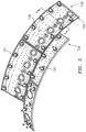
- Each combustor wall assembly 60, 62 generally includes a respective support shell 68, 70 which supports one or more liner panels 72, 74 mounted within the respective support shell 68, 70.
- Each of the liner panels 72, 74 may be generally rectilinear with a circumferential arc and/or may be manufactured of, for example, a nickel based super alloy, ceramic or other temperature resistant material and are arranged to form a liner array.
- the liner array includes a multiple of forward liner panels 72A and a multiple of aft liner panels 72B that are circumferentially staggered to line the outer shell 68.
- a multiple of forward liner panels 74A and a multiple of aft liner panels 74B are circumferentially staggered to line the inner shell 70.
- the combustor 56 further includes a forward assembly 80 immediately downstream of the compressor section 24 to receive compressed airflow therefrom.
- the forward assembly 80 generally includes an annular hood 82 and a bulkhead assembly 84 that support a multiple of fuel nozzles 86 (one shown) and a multiple of swirlers 90 (one shown).
- the annular hood 82 extends radially between, and is secured to, the forwardmost ends of the combustor wall assemblies 60, 62.
- the annular hood 82 includes a multiple of circumferentially distributed hood ports 94 that accommodate the respective fuel nozzle 86 and introduce air into the forward end of the combustion chamber 66 through a respective swirler 90.
- the bulkhead assembly 84 includes a bulkhead support shell 96 secured to the combustor wall assemblies 60, 62, and a multiple of circumferentially distributed bulkhead liner panels 98 secured to the bulkhead support shell 96.
- Each fuel nozzle 86 may be secured to the diffuser case module 64 and project through one of the hood ports 94 and respective swirlers 90.
- the forward assembly 80 introduces core combustion air into the forward section of the combustion chamber 66 while the remainder enters the outer annular plenum 76 and the inner annular plenum 78.
- the multiple of fuel nozzles 86 and adjacent structure generate a fuel-air mixture that supports stable combustion in the combustion chamber 66.
- NGVs Nozzle Guide Vanes
- the NGVs 54A are static engine components which direct core airflow combustion gases onto turbine blades in the turbine section 28 to facilitate the conversion of pressure energy into kinetic energy.
- the core airflow combustion gases are also accelerated by the NGVs 54A because of their convergent shape and are typically given a "spin” or a "swirl” in the direction of turbine rotor rotation.
- a multiple of studs 100 extend from the liner panels 72, 74 so as to permit the liner panels 72, 74 to be mounted to their respective support shells 68, 70 with fasteners 102 such as nuts. That is, the studs 100 project rigidly from the liner panels 72, 74 through the respective support shells 68, 70 to receive the fasteners 102 at a threaded distal end section thereof to define one or more impingement cavities 106.
- the liner panels 72, 74 typically include one or more rails 120 which extend from extend from a cold side 110 thereof. The rail 120 extends around the periphery of the cold side 110 (see FIG.
- the rails 120 at least extend around the cold side 110 periphery and may include further internal rails to define additional compartments.
- a multiple of cooling impingement passages 104 penetrate through the support shells 68, 70 to allow air from the respective annular plenums 76, 78 to enter impingement cavities 106 formed within the combustor wall assemblies 60, 62 between the respective support shells 68, 70 and the liner panels 72, 74.
- the cooling impingement passages 104 are generally normal to the surface of the liner panels 72, 74.
- the air in the cavities 106 provides cold side impingement cooling of the liner panels 72, 74 that is generally defined herein as heat removal via internal convection.
- a multiple of effusion passages 108 penetrate through each of the liner panels 72, 74.
- the geometry of the passages e.g., diameter, shape, density, surface angle, incidence angle, etc.
- the combination of impingement passages 104 and effusion passages 108 may be referred to as an Impingement Film Floatwall (IFF) assembly.
- IFF Impingement Film Floatwall
- the effusion passages 108 allow the air to pass from each cavity 106 defined in part by the cold side 110 of the liner panels 72, 74 to a hot side 112 thereof to facilitate the formation of a relatively thin, cool, insulating blanket of cooling air along the hot side 112.
- the effusion passages 108 are generally more numerous than the impingement passages 104 to promote the development of a sheath of film cooling along the hot side 112.
- Film cooling as defined herein is the introduction of a relatively cooler air at one or more discrete locations along a surface exposed to a high temperature environment to protect that surface in the region of the air injection as well as downstream thereof.
- a multiple of dilution passages 116 penetrate through both the respective support shells 68, 70 and the liner panels 72, 74 along a common axis D (see FIG. 6 ).
- the dilution passages 116 are located downstream of the forward assembly 80 to quench the hot combustion gases within the combustion chamber 66 by direct supply of cooling air from the respective annular plenums 76, 78.
- P1 is a pressure in front of the fan section 22;
- P2 is a pressure at the leading edge of the fan 42;
- P2.5 is the pressure between the LPC 44 and the HPC 52;
- P3 is the pressure aft of the HPC 52 within the diffuser case module;
- P4 is the pressure aft of the combustion chamber 66 adjacent the NGVs;
- P4.5 is the pressure between the HPT 54 and the LPT 46;
- P5 is the pressure aft of the LPT 46 (see FIGS. 1 and 2 ).
- HPC 52 pressures exist in concert with a cooling air supply pressure decrease at higher altitudes. That is, available pressures may not be sufficient for cooling requirements at high altitudes as the heat transfer capability of the liner panels 72, 74 decrease by a factor of about two (2) as supply pressures decreases from, for example, sea level flight operations to higher altitude flight operations.
- Each rail 120 includes a notch 122 to receive a seal 124 (also shown in FIG. 6 ).
- the "notch" as defined herein includes various recesses, grooves, marks, cuts, and other surfaces for the seal 124.
- the notch 122 is a generally L-shaped cut out on the impingement cavity 106 side of the rail 120.
- the notch 122 in the rail 120 surrounds the impingement cavity 106 and is recessed with respect to a rail surface 126 of the rail 120. That is, the interface surfaces 126 contact the respective support shells 68, 70 to form a rail seal interface 128 (see FIG. 7 ).
- the seal 124 in this disclosed non-limiting embodiment is a C-shaped seal with an opening 130 thereof directed toward the impingement cavity 106.
- the seal 124 may be manufactured of, for example, a 625 nickel alloy material.
- the rail seal interface 128 contacts the respective support shells 68, 70 and the seal 124 is at least partially compressed.
- the seal 124 thereby facilitates sealing of the impingement cavity 106 in addition to the face contact interface at the rail interface surface 126.
- the opening 130 is directed toward the impingement cavity 106, the pressure within the impingement cavity 106 serves to open the C-shaped seal and facilitate the sealing interface 128. That is, a relatively higher pressure resistant seal interface 128 is formed to minimize leakage from each impingement cavity 106.
- the seal 124 may be brazed or otherwise affixed at least partially within the notch 122. Alternatively, the seal 124 may be interference fit within the notch 122 as a single continuous seal 124 may surround the periphery of each impingement cavity 106.
- the seal 124 facilitates an increased pressure drop across the combustor 56.
- the pressure within the impingement cavities 106 is about equal to a pressure within the diffuser case module 64. That is, the pressure drop is approximately 50-50 or higher as compared to a more conventional 80-20 pressure drop with but a face rail contact interface alone. In other words, 80% of the conventional pressure drop is utilized for impingement flow while 20% is utilized for effusion flow.
- the seal 124 facilitates a pressure drop across the support shell 68, 70 of less than about 80% and a pressure drop across the liner panels 72, 74 greater than about 20%. Testing has shown that the more aggressive (50-50 or higher) pressure drop split effectively increases panel cooling.
- the seal 124 readily controls leakage around the liner panels 72, 74 facilitate formation of a relatively larger pressure drops across the liner panels 72, 74 to increase cooling effectiveness.
Landscapes
- Engineering & Computer Science (AREA)
- Chemical & Material Sciences (AREA)
- Combustion & Propulsion (AREA)
- Mechanical Engineering (AREA)
- General Engineering & Computer Science (AREA)
- Turbine Rotor Nozzle Sealing (AREA)
Claims (7)
- Chambre de combustion (56) d'un moteur à turbine à gaz (20), la chambre de combustion comprenant :une enveloppe (68, 70) avec une multiplicité de passages d'écoulement d'impact (104) couplés fluidiquement à une cavité d'impact (106) ;un panneau de chemisage (72, 74) monté sur l'enveloppe (68, 70), le panneau de chemisage (72, 74) incluant un rail (120), le rail (120) incluant une encoche (122) qui fait face à la cavité d'impact (106), le rail (120) assurant l'interface avec l'enveloppe (68, 70), pour définir la cavité d'impact (106) entre eux ;un joint (124) à l'intérieur de l'encoche (122), le joint (124) étant en contact avec l'enveloppe (68, 70) ; etune multiplicité de passages d'écoulement d'effusion (108) à travers le panneau de chemisage (72, 74),dans laquelle la chambre de combustion (56) est configurée de sorte que de l'air dirigé à travers l'enveloppe (68, 70) et le panneau de chemisage (72, 74) forme une chute de pression à travers l'enveloppe (68, 70) qui est inférieure à environ 80 % et supérieure à environ 50 % d'une chute de pression à travers la chambre de combustion (56), et de sorte qu'une chute de pression à travers le panneau de chemisage (72, 74) est supérieure à environ 20 % et inférieure à environ 50 % de la chute de pression à travers la chambre de combustion (56),dans laquelle le rail (120) inclut une surface d'interface (126) au moins partiellement en contact avec l'enveloppe (68, 70), le rail (120) entoure la cavité d'impact (106), et le rail (120) s'étend à partir d'un côté froid (110) du panneau de chemisage (72, 74),dans laquelle la multiplicité de passages d'écoulement d'impact (104) sont à travers l'enveloppe de support (68, 70), dans laquelle le joint (124) entoure la cavité d'impact (106).
- Chambre de combustion selon la revendication 1, comprenant en outre une pluralité de goujons (100) s'étendant à partir d'un côté froid (110) du panneau de chemisage (72, 74), dans laquelle les goujons (100) s'étendent à travers l'enveloppe (68, 70).
- Chambre de combustion selon la revendication 1 ou 2, dans laquelle le joint (124) est un joint en C.
- Chambre de combustion selon la revendication 3, dans laquelle une ouverture (130) du joint en C (124) est dirigée vers la cavité d'impact (106).
- Procédé de refroidissement d'un ensemble de paroi à l'intérieur d'une chambre de combustion (56) selon une quelconque revendication précédente, le procédé comprenant :le scellage d'une interface entre l'enveloppe de support (68, 70) et le panneau de chemisage (72, 74) via le joint (124) ;la direction de l'air à travers l'enveloppe de support et le panneau de chemisage (72, 74) pour former une chute de pression à travers l'enveloppe de support (68, 70) qui est inférieure à environ 80 % et supérieure à 50 % d'une chute de pression à travers la chambre de combustion (56) et pour former en outre une chute de pression à travers le panneau de chemisage (72, 74) supérieure à environ 20 % et inférieure à environ 50 % de la chute de pression à travers la chambre de combustion (56).
- Procédé selon la revendication 5, comprenant en outre la compression du joint (124) entre l'enveloppe de support (68, 70) et le panneau de chemisage (72, 74).
- Procédé selon la revendication 5 ou 6, comprenant en autre la mise sous pression du joint (124).
Applications Claiming Priority (2)
| Application Number | Priority Date | Filing Date | Title |
|---|---|---|---|
| US201361877728P | 2013-09-13 | 2013-09-13 | |
| PCT/US2014/046381 WO2015038232A1 (fr) | 2013-09-13 | 2014-07-11 | Panneau de chemisage de chambre de combustion hermétiquement scellé pour une turbine à gaz |
Publications (3)
| Publication Number | Publication Date |
|---|---|
| EP3044444A1 EP3044444A1 (fr) | 2016-07-20 |
| EP3044444A4 EP3044444A4 (fr) | 2016-10-05 |
| EP3044444B1 true EP3044444B1 (fr) | 2019-11-06 |
Family
ID=52666131
Family Applications (1)
| Application Number | Title | Priority Date | Filing Date |
|---|---|---|---|
| EP14843958.1A Active EP3044444B1 (fr) | 2013-09-13 | 2014-07-11 | Chambre de combustion pour une turbine à gaz avec un panneau de chemisage hermétiquement scellé |
Country Status (3)
| Country | Link |
|---|---|
| US (1) | US10816201B2 (fr) |
| EP (1) | EP3044444B1 (fr) |
| WO (1) | WO2015038232A1 (fr) |
Families Citing this family (10)
| Publication number | Priority date | Publication date | Assignee | Title |
|---|---|---|---|---|
| EP2910765B1 (fr) * | 2014-02-21 | 2017-10-25 | Rolls-Royce Corporation | Échangeurs de chaleur monophasés à micro/mini-canaux pour le refroidissement intermédiaire d'une turbine à gaz et procede correspondant |
| EP3572758B1 (fr) | 2014-02-21 | 2023-04-05 | Rolls-Royce Corporation | Échangeurs de chaleur à microcanaux pour le refroidissement et la condensation d'une turbine à gaz |
| EP2930314B1 (fr) * | 2014-04-08 | 2022-06-08 | Rolls-Royce Corporation | Générateur avec amplificateur de refroidissement d'air contrôlé |
| US10739001B2 (en) | 2017-02-14 | 2020-08-11 | Raytheon Technologies Corporation | Combustor liner panel shell interface for a gas turbine engine combustor |
| US10830434B2 (en) | 2017-02-23 | 2020-11-10 | Raytheon Technologies Corporation | Combustor liner panel end rail with curved interface passage for a gas turbine engine combustor |
| US10718521B2 (en) | 2017-02-23 | 2020-07-21 | Raytheon Technologies Corporation | Combustor liner panel end rail cooling interface passage for a gas turbine engine combustor |
| US10677462B2 (en) | 2017-02-23 | 2020-06-09 | Raytheon Technologies Corporation | Combustor liner panel end rail angled cooling interface passage for a gas turbine engine combustor |
| US10823411B2 (en) | 2017-02-23 | 2020-11-03 | Raytheon Technologies Corporation | Combustor liner panel end rail cooling enhancement features for a gas turbine engine combustor |
| US10941937B2 (en) * | 2017-03-20 | 2021-03-09 | Raytheon Technologies Corporation | Combustor liner with gasket for gas turbine engine |
| US20220018541A1 (en) * | 2020-07-16 | 2022-01-20 | Raytheon Technologies Corporation | Article and method for manufacturing an expanded combustor liner |
Family Cites Families (53)
| Publication number | Priority date | Publication date | Assignee | Title |
|---|---|---|---|---|
| US4253301A (en) * | 1978-10-13 | 1981-03-03 | General Electric Company | Fuel injection staged sectoral combustor for burning low-BTU fuel gas |
| US4302941A (en) * | 1980-04-02 | 1981-12-01 | United Technologies Corporation | Combuster liner construction for gas turbine engine |
| US4628694A (en) * | 1983-12-19 | 1986-12-16 | General Electric Company | Fabricated liner article and method |
| FR2599821B1 (fr) * | 1986-06-04 | 1988-09-02 | Snecma | Chambre de combustion pour turbomachines a orifices de melange assurant le positionnement de la paroi chaude sur la paroi froide |
| US4749298A (en) * | 1987-04-30 | 1988-06-07 | United Technologies Corporation | Temperature resistant fastener arrangement |
| FR2644209B1 (fr) * | 1989-03-08 | 1991-05-03 | Snecma | Chemise de protection thermique pour canal chaud de turboreacteur |
| US5363643A (en) * | 1993-02-08 | 1994-11-15 | General Electric Company | Segmented combustor |
| FR2708086B1 (fr) * | 1993-06-30 | 1995-09-01 | Snecma | Structure tubulaire sectorisée travaillant à l'implosion. |
| GB2298266A (en) * | 1995-02-23 | 1996-08-28 | Rolls Royce Plc | A cooling arrangement for heat resistant tiles in a gas turbine engine combustor |
| US5758503A (en) * | 1995-05-03 | 1998-06-02 | United Technologies Corporation | Gas turbine combustor |
| US5630319A (en) * | 1995-05-12 | 1997-05-20 | General Electric Company | Dome assembly for a multiple annular combustor |
| US5974805A (en) | 1997-10-28 | 1999-11-02 | Rolls-Royce Plc | Heat shielding for a turbine combustor |
| EP1022437A1 (fr) * | 1999-01-19 | 2000-07-26 | Siemens Aktiengesellschaft | Elément de construction à l'usage d'une machine thermique |
| US6148600A (en) | 1999-02-26 | 2000-11-21 | General Electric Company | One-piece sheet metal cowl for combustor of a gas turbine engine and method of configuring same |
| GB2361304A (en) * | 2000-04-14 | 2001-10-17 | Rolls Royce Plc | Combustor wall tile |
| GB2361303B (en) * | 2000-04-14 | 2004-10-20 | Rolls Royce Plc | Wall structure for a gas turbine engine combustor |
| EP1260767A1 (fr) * | 2001-05-25 | 2002-11-27 | Siemens Aktiengesellschaft | Ensemble bouclier thermique pour un composant acheminant un gaz chaud, notamment pour des pièces de structure de turbines à gaz, ainsi que le procédé de fabrication d'un tel ensemble |
| US6655146B2 (en) | 2001-07-31 | 2003-12-02 | General Electric Company | Hybrid film cooled combustor liner |
| EP1302723A1 (fr) * | 2001-10-15 | 2003-04-16 | Siemens Aktiengesellschaft | Revêtement pour parois intérieures de chambre de combustion |
| DE10155420A1 (de) * | 2001-11-12 | 2003-05-22 | Rolls Royce Deutschland | Hitzeschildanordnung mit Dichtungselement |
| US6701714B2 (en) * | 2001-12-05 | 2004-03-09 | United Technologies Corporation | Gas turbine combustor |
| RU2300033C2 (ru) * | 2002-07-05 | 2007-05-27 | Альстом Текнолоджи Лтд | Уплотнительное устройство для герметизации щели между двумя соседними конструкционными элементами |
| EP1400751A1 (fr) | 2002-09-17 | 2004-03-24 | Siemens Aktiengesellschaft | Chambre de combustion pour turbine à gaz |
| US6792757B2 (en) | 2002-11-05 | 2004-09-21 | Honeywell International Inc. | Gas turbine combustor heat shield impingement cooling baffle |
| US6964170B2 (en) * | 2003-04-28 | 2005-11-15 | Pratt & Whitney Canada Corp. | Noise reducing combustor |
| FR2856468B1 (fr) | 2003-06-17 | 2007-11-23 | Snecma Moteurs | Chambre de combustion annulaire de turbomachine |
| EP1507116A1 (fr) * | 2003-08-13 | 2005-02-16 | Siemens Aktiengesellschaft | Ensemble bouclier thermique pour un composant acheminant un gaz chaud, notamment pour une chambre de combustion de turbine à gaz |
| US8695989B2 (en) * | 2004-04-30 | 2014-04-15 | Siemens Aktiengesellschaft | Hot gas seal |
| US7010921B2 (en) | 2004-06-01 | 2006-03-14 | General Electric Company | Method and apparatus for cooling combustor liner and transition piece of a gas turbine |
| US7140185B2 (en) * | 2004-07-12 | 2006-11-28 | United Technologies Corporation | Heatshielded article |
| US7373778B2 (en) | 2004-08-26 | 2008-05-20 | General Electric Company | Combustor cooling with angled segmented surfaces |
| US7260936B2 (en) | 2004-08-27 | 2007-08-28 | Pratt & Whitney Canada Corp. | Combustor having means for directing air into the combustion chamber in a spiral pattern |
| EP1650503A1 (fr) | 2004-10-25 | 2006-04-26 | Siemens Aktiengesellschaft | Méthode de refroidissement d'un bouclier thermique et bouclier thermique |
| DE102005046731A1 (de) * | 2005-04-19 | 2006-11-02 | Siemens Ag | Hitzeschildanordnung |
| US7770397B2 (en) | 2006-11-03 | 2010-08-10 | Pratt & Whitney Canada Corp. | Combustor dome panel heat shield cooling |
| US7721548B2 (en) | 2006-11-17 | 2010-05-25 | Pratt & Whitney Canada Corp. | Combustor liner and heat shield assembly |
| US7748221B2 (en) | 2006-11-17 | 2010-07-06 | Pratt & Whitney Canada Corp. | Combustor heat shield with variable cooling |
| US7681398B2 (en) | 2006-11-17 | 2010-03-23 | Pratt & Whitney Canada Corp. | Combustor liner and heat shield assembly |
| FR2918443B1 (fr) | 2007-07-04 | 2009-10-30 | Snecma Sa | Chambre de combustion comportant des deflecteurs de protection thermique de fond de chambre et moteur a turbine a gaz en etant equipe |
| FR2921462B1 (fr) | 2007-09-21 | 2012-08-24 | Snecma | Chambre de combustion annulaire de moteur a turbine a gaz |
| MY161317A (en) * | 2008-02-20 | 2017-04-14 | General Electric Technology Gmbh | Gas turbine |
| GB0803366D0 (en) * | 2008-02-26 | 2008-04-02 | Rolls Royce Plc | Nose cone assembly |
| US8056342B2 (en) * | 2008-06-12 | 2011-11-15 | United Technologies Corporation | Hole pattern for gas turbine combustor |
| US20100095680A1 (en) * | 2008-10-22 | 2010-04-22 | Honeywell International Inc. | Dual wall structure for use in a combustor of a gas turbine engine |
| US8448416B2 (en) | 2009-03-30 | 2013-05-28 | General Electric Company | Combustor liner |
| GB0907278D0 (en) * | 2009-04-29 | 2009-06-10 | Rolls Royce Plc | A seal arrangement and a method of repairing a seal arrangement |
| US8359866B2 (en) * | 2010-02-04 | 2013-01-29 | United Technologies Corporation | Combustor liner segment seal member |
| US9133721B2 (en) | 2010-11-15 | 2015-09-15 | Siemens Energy, Inc. | Turbine transition component formed from a two section, air-cooled multi-layer outer panel for use in a gas turbine engine |
| US8827642B2 (en) * | 2011-01-31 | 2014-09-09 | General Electric Company | Flexible seal for turbine engine |
| US9052111B2 (en) * | 2012-06-22 | 2015-06-09 | United Technologies Corporation | Turbine engine combustor wall with non-uniform distribution of effusion apertures |
| WO2014137409A1 (fr) * | 2013-03-07 | 2014-09-12 | Rolls-Royce Corporation | Joint d'étanchéité à soufflets souples d'allumeur de turbine à gaz à chemise de combustion en céramique |
| DE102014204481A1 (de) * | 2014-03-11 | 2015-09-17 | Rolls-Royce Deutschland Ltd & Co Kg | Brennkammer einer Gasturbine |
| US9534785B2 (en) * | 2014-08-26 | 2017-01-03 | Pratt & Whitney Canada Corp. | Heat shield labyrinth seal |
-
2014
- 2014-07-11 US US14/913,165 patent/US10816201B2/en active Active
- 2014-07-11 WO PCT/US2014/046381 patent/WO2015038232A1/fr active Application Filing
- 2014-07-11 EP EP14843958.1A patent/EP3044444B1/fr active Active
Non-Patent Citations (1)
| Title |
|---|
| None * |
Also Published As
| Publication number | Publication date |
|---|---|
| WO2015038232A1 (fr) | 2015-03-19 |
| EP3044444A1 (fr) | 2016-07-20 |
| US10816201B2 (en) | 2020-10-27 |
| EP3044444A4 (fr) | 2016-10-05 |
| US20160201914A1 (en) | 2016-07-14 |
Similar Documents
| Publication | Publication Date | Title |
|---|---|---|
| EP2984317B1 (fr) | Refroidissement de jonction en t de panneau de chambre de combustion | |
| EP3044444B1 (fr) | Chambre de combustion pour une turbine à gaz avec un panneau de chemisage hermétiquement scellé | |
| US10677462B2 (en) | Combustor liner panel end rail angled cooling interface passage for a gas turbine engine combustor | |
| EP3366997B1 (fr) | Caractéristiques d'amélioration de refroidissement de rail d'extrémité de panneau de chemise de chambre de combustion pour une chambre de combustion de turbine à gaz | |
| EP3361158B1 (fr) | Chambre de combustion pour une turbine à gaz | |
| US10731858B2 (en) | Controlled variation of pressure drop through effusion cooling in a double walled combustor of a gas turbine engine | |
| US20160169516A1 (en) | Gas turbine engine combustor bulkhead assembly | |
| US10808937B2 (en) | Gas turbine engine wall assembly with offset rail | |
| EP3315730A1 (fr) | Joint de chambre de combustion pour chambre de combustion de moteur de turbine à gaz | |
| US20180266686A1 (en) | Regulated combustor liner panel for a gas turbine engine combustor | |
| US10830433B2 (en) | Axial non-linear interface for combustor liner panels in a gas turbine combustor | |
| US10655856B2 (en) | Dilution passage arrangement for gas turbine engine combustor | |
| EP3321585B1 (fr) | Panneau de chemise de chambre de combustion non plane pour chambre de combustion de turbine à gaz | |
| US20180231249A1 (en) | Non-planar combustor liner panel for a gas turbine engine combustor | |
| EP3315862B1 (fr) | Panneau de revêtement moulé de chambre de combustion comportant un bord a rayon pour chambre de combustion de turbine à gaz |
Legal Events
| Date | Code | Title | Description |
|---|---|---|---|
| PUAI | Public reference made under article 153(3) epc to a published international application that has entered the european phase |
Free format text: ORIGINAL CODE: 0009012 |
|
| 17P | Request for examination filed |
Effective date: 20160413 |
|
| AK | Designated contracting states |
Kind code of ref document: A1 Designated state(s): AL AT BE BG CH CY CZ DE DK EE ES FI FR GB GR HR HU IE IS IT LI LT LU LV MC MK MT NL NO PL PT RO RS SE SI SK SM TR |
|
| AX | Request for extension of the european patent |
Extension state: BA ME |
|
| A4 | Supplementary search report drawn up and despatched |
Effective date: 20160905 |
|
| RIC1 | Information provided on ipc code assigned before grant |
Ipc: F02C 7/24 20060101AFI20160830BHEP Ipc: F23R 3/42 20060101ALI20160830BHEP Ipc: F02C 7/28 20060101ALI20160830BHEP |
|
| RAP1 | Party data changed (applicant data changed or rights of an application transferred) |
Owner name: UNITED TECHNOLOGIES CORPORATION |
|
| DAX | Request for extension of the european patent (deleted) | ||
| STAA | Information on the status of an ep patent application or granted ep patent |
Free format text: STATUS: EXAMINATION IS IN PROGRESS |
|
| 17Q | First examination report despatched |
Effective date: 20180406 |
|
| GRAP | Despatch of communication of intention to grant a patent |
Free format text: ORIGINAL CODE: EPIDOSNIGR1 |
|
| STAA | Information on the status of an ep patent application or granted ep patent |
Free format text: STATUS: GRANT OF PATENT IS INTENDED |
|
| INTG | Intention to grant announced |
Effective date: 20190506 |
|
| GRAS | Grant fee paid |
Free format text: ORIGINAL CODE: EPIDOSNIGR3 |
|
| GRAJ | Information related to disapproval of communication of intention to grant by the applicant or resumption of examination proceedings by the epo deleted |
Free format text: ORIGINAL CODE: EPIDOSDIGR1 |
|
| GRAL | Information related to payment of fee for publishing/printing deleted |
Free format text: ORIGINAL CODE: EPIDOSDIGR3 |
|
| STAA | Information on the status of an ep patent application or granted ep patent |
Free format text: STATUS: EXAMINATION IS IN PROGRESS |
|
| GRAR | Information related to intention to grant a patent recorded |
Free format text: ORIGINAL CODE: EPIDOSNIGR71 |
|
| STAA | Information on the status of an ep patent application or granted ep patent |
Free format text: STATUS: GRANT OF PATENT IS INTENDED |
|
| GRAA | (expected) grant |
Free format text: ORIGINAL CODE: 0009210 |
|
| STAA | Information on the status of an ep patent application or granted ep patent |
Free format text: STATUS: THE PATENT HAS BEEN GRANTED |
|
| INTC | Intention to grant announced (deleted) | ||
| INTG | Intention to grant announced |
Effective date: 20190920 |
|
| AK | Designated contracting states |
Kind code of ref document: B1 Designated state(s): AL AT BE BG CH CY CZ DE DK EE ES FI FR GB GR HR HU IE IS IT LI LT LU LV MC MK MT NL NO PL PT RO RS SE SI SK SM TR |
|
| REG | Reference to a national code |
Ref country code: GB Ref legal event code: FG4D |
|
| REG | Reference to a national code |
Ref country code: CH Ref legal event code: EP Ref country code: AT Ref legal event code: REF Ref document number: 1199006 Country of ref document: AT Kind code of ref document: T Effective date: 20191115 |
|
| REG | Reference to a national code |
Ref country code: IE Ref legal event code: FG4D |
|
| REG | Reference to a national code |
Ref country code: DE Ref legal event code: R096 Ref document number: 602014056476 Country of ref document: DE |
|
| REG | Reference to a national code |
Ref country code: NL Ref legal event code: MP Effective date: 20191106 |
|
| REG | Reference to a national code |
Ref country code: LT Ref legal event code: MG4D |
|
| PG25 | Lapsed in a contracting state [announced via postgrant information from national office to epo] |
Ref country code: FI Free format text: LAPSE BECAUSE OF FAILURE TO SUBMIT A TRANSLATION OF THE DESCRIPTION OR TO PAY THE FEE WITHIN THE PRESCRIBED TIME-LIMIT Effective date: 20191106 Ref country code: NO Free format text: LAPSE BECAUSE OF FAILURE TO SUBMIT A TRANSLATION OF THE DESCRIPTION OR TO PAY THE FEE WITHIN THE PRESCRIBED TIME-LIMIT Effective date: 20200206 Ref country code: LT Free format text: LAPSE BECAUSE OF FAILURE TO SUBMIT A TRANSLATION OF THE DESCRIPTION OR TO PAY THE FEE WITHIN THE PRESCRIBED TIME-LIMIT Effective date: 20191106 Ref country code: NL Free format text: LAPSE BECAUSE OF FAILURE TO SUBMIT A TRANSLATION OF THE DESCRIPTION OR TO PAY THE FEE WITHIN THE PRESCRIBED TIME-LIMIT Effective date: 20191106 Ref country code: PL Free format text: LAPSE BECAUSE OF FAILURE TO SUBMIT A TRANSLATION OF THE DESCRIPTION OR TO PAY THE FEE WITHIN THE PRESCRIBED TIME-LIMIT Effective date: 20191106 Ref country code: GR Free format text: LAPSE BECAUSE OF FAILURE TO SUBMIT A TRANSLATION OF THE DESCRIPTION OR TO PAY THE FEE WITHIN THE PRESCRIBED TIME-LIMIT Effective date: 20200207 Ref country code: PT Free format text: LAPSE BECAUSE OF FAILURE TO SUBMIT A TRANSLATION OF THE DESCRIPTION OR TO PAY THE FEE WITHIN THE PRESCRIBED TIME-LIMIT Effective date: 20200306 Ref country code: LV Free format text: LAPSE BECAUSE OF FAILURE TO SUBMIT A TRANSLATION OF THE DESCRIPTION OR TO PAY THE FEE WITHIN THE PRESCRIBED TIME-LIMIT Effective date: 20191106 Ref country code: SE Free format text: LAPSE BECAUSE OF FAILURE TO SUBMIT A TRANSLATION OF THE DESCRIPTION OR TO PAY THE FEE WITHIN THE PRESCRIBED TIME-LIMIT Effective date: 20191106 Ref country code: BG Free format text: LAPSE BECAUSE OF FAILURE TO SUBMIT A TRANSLATION OF THE DESCRIPTION OR TO PAY THE FEE WITHIN THE PRESCRIBED TIME-LIMIT Effective date: 20200206 |
|
| PG25 | Lapsed in a contracting state [announced via postgrant information from national office to epo] |
Ref country code: RS Free format text: LAPSE BECAUSE OF FAILURE TO SUBMIT A TRANSLATION OF THE DESCRIPTION OR TO PAY THE FEE WITHIN THE PRESCRIBED TIME-LIMIT Effective date: 20191106 Ref country code: IS Free format text: LAPSE BECAUSE OF FAILURE TO SUBMIT A TRANSLATION OF THE DESCRIPTION OR TO PAY THE FEE WITHIN THE PRESCRIBED TIME-LIMIT Effective date: 20200306 Ref country code: HR Free format text: LAPSE BECAUSE OF FAILURE TO SUBMIT A TRANSLATION OF THE DESCRIPTION OR TO PAY THE FEE WITHIN THE PRESCRIBED TIME-LIMIT Effective date: 20191106 |
|
| PG25 | Lapsed in a contracting state [announced via postgrant information from national office to epo] |
Ref country code: AL Free format text: LAPSE BECAUSE OF FAILURE TO SUBMIT A TRANSLATION OF THE DESCRIPTION OR TO PAY THE FEE WITHIN THE PRESCRIBED TIME-LIMIT Effective date: 20191106 |
|
| PG25 | Lapsed in a contracting state [announced via postgrant information from national office to epo] |
Ref country code: DK Free format text: LAPSE BECAUSE OF FAILURE TO SUBMIT A TRANSLATION OF THE DESCRIPTION OR TO PAY THE FEE WITHIN THE PRESCRIBED TIME-LIMIT Effective date: 20191106 Ref country code: RO Free format text: LAPSE BECAUSE OF FAILURE TO SUBMIT A TRANSLATION OF THE DESCRIPTION OR TO PAY THE FEE WITHIN THE PRESCRIBED TIME-LIMIT Effective date: 20191106 Ref country code: EE Free format text: LAPSE BECAUSE OF FAILURE TO SUBMIT A TRANSLATION OF THE DESCRIPTION OR TO PAY THE FEE WITHIN THE PRESCRIBED TIME-LIMIT Effective date: 20191106 Ref country code: CZ Free format text: LAPSE BECAUSE OF FAILURE TO SUBMIT A TRANSLATION OF THE DESCRIPTION OR TO PAY THE FEE WITHIN THE PRESCRIBED TIME-LIMIT Effective date: 20191106 Ref country code: ES Free format text: LAPSE BECAUSE OF FAILURE TO SUBMIT A TRANSLATION OF THE DESCRIPTION OR TO PAY THE FEE WITHIN THE PRESCRIBED TIME-LIMIT Effective date: 20191106 |
|
| REG | Reference to a national code |
Ref country code: DE Ref legal event code: R097 Ref document number: 602014056476 Country of ref document: DE |
|
| REG | Reference to a national code |
Ref country code: AT Ref legal event code: MK05 Ref document number: 1199006 Country of ref document: AT Kind code of ref document: T Effective date: 20191106 |
|
| PG25 | Lapsed in a contracting state [announced via postgrant information from national office to epo] |
Ref country code: SK Free format text: LAPSE BECAUSE OF FAILURE TO SUBMIT A TRANSLATION OF THE DESCRIPTION OR TO PAY THE FEE WITHIN THE PRESCRIBED TIME-LIMIT Effective date: 20191106 Ref country code: SM Free format text: LAPSE BECAUSE OF FAILURE TO SUBMIT A TRANSLATION OF THE DESCRIPTION OR TO PAY THE FEE WITHIN THE PRESCRIBED TIME-LIMIT Effective date: 20191106 |
|
| PLBE | No opposition filed within time limit |
Free format text: ORIGINAL CODE: 0009261 |
|
| STAA | Information on the status of an ep patent application or granted ep patent |
Free format text: STATUS: NO OPPOSITION FILED WITHIN TIME LIMIT |
|
| 26N | No opposition filed |
Effective date: 20200807 |
|
| PG25 | Lapsed in a contracting state [announced via postgrant information from national office to epo] |
Ref country code: SI Free format text: LAPSE BECAUSE OF FAILURE TO SUBMIT A TRANSLATION OF THE DESCRIPTION OR TO PAY THE FEE WITHIN THE PRESCRIBED TIME-LIMIT Effective date: 20191106 Ref country code: AT Free format text: LAPSE BECAUSE OF FAILURE TO SUBMIT A TRANSLATION OF THE DESCRIPTION OR TO PAY THE FEE WITHIN THE PRESCRIBED TIME-LIMIT Effective date: 20191106 |
|
| PG25 | Lapsed in a contracting state [announced via postgrant information from national office to epo] |
Ref country code: IT Free format text: LAPSE BECAUSE OF FAILURE TO SUBMIT A TRANSLATION OF THE DESCRIPTION OR TO PAY THE FEE WITHIN THE PRESCRIBED TIME-LIMIT Effective date: 20191106 |
|
| PG25 | Lapsed in a contracting state [announced via postgrant information from national office to epo] |
Ref country code: MC Free format text: LAPSE BECAUSE OF FAILURE TO SUBMIT A TRANSLATION OF THE DESCRIPTION OR TO PAY THE FEE WITHIN THE PRESCRIBED TIME-LIMIT Effective date: 20191106 |
|
| REG | Reference to a national code |
Ref country code: CH Ref legal event code: PL |
|
| REG | Reference to a national code |
Ref country code: BE Ref legal event code: MM Effective date: 20200731 |
|
| PG25 | Lapsed in a contracting state [announced via postgrant information from national office to epo] |
Ref country code: LI Free format text: LAPSE BECAUSE OF NON-PAYMENT OF DUE FEES Effective date: 20200731 Ref country code: LU Free format text: LAPSE BECAUSE OF NON-PAYMENT OF DUE FEES Effective date: 20200711 Ref country code: CH Free format text: LAPSE BECAUSE OF NON-PAYMENT OF DUE FEES Effective date: 20200731 |
|
| PG25 | Lapsed in a contracting state [announced via postgrant information from national office to epo] |
Ref country code: BE Free format text: LAPSE BECAUSE OF NON-PAYMENT OF DUE FEES Effective date: 20200731 |
|
| PG25 | Lapsed in a contracting state [announced via postgrant information from national office to epo] |
Ref country code: IE Free format text: LAPSE BECAUSE OF NON-PAYMENT OF DUE FEES Effective date: 20200711 |
|
| PG25 | Lapsed in a contracting state [announced via postgrant information from national office to epo] |
Ref country code: TR Free format text: LAPSE BECAUSE OF FAILURE TO SUBMIT A TRANSLATION OF THE DESCRIPTION OR TO PAY THE FEE WITHIN THE PRESCRIBED TIME-LIMIT Effective date: 20191106 Ref country code: MT Free format text: LAPSE BECAUSE OF FAILURE TO SUBMIT A TRANSLATION OF THE DESCRIPTION OR TO PAY THE FEE WITHIN THE PRESCRIBED TIME-LIMIT Effective date: 20191106 Ref country code: CY Free format text: LAPSE BECAUSE OF FAILURE TO SUBMIT A TRANSLATION OF THE DESCRIPTION OR TO PAY THE FEE WITHIN THE PRESCRIBED TIME-LIMIT Effective date: 20191106 |
|
| PG25 | Lapsed in a contracting state [announced via postgrant information from national office to epo] |
Ref country code: MK Free format text: LAPSE BECAUSE OF FAILURE TO SUBMIT A TRANSLATION OF THE DESCRIPTION OR TO PAY THE FEE WITHIN THE PRESCRIBED TIME-LIMIT Effective date: 20191106 |
|
| REG | Reference to a national code |
Ref country code: DE Ref legal event code: R081 Ref document number: 602014056476 Country of ref document: DE Owner name: RAYTHEON TECHNOLOGIES CORPORATION (N.D.GES.D.S, US Free format text: FORMER OWNER: UNITED TECHNOLOGIES CORPORATION, FARMINGTON, CONN., US |
|
| P01 | Opt-out of the competence of the unified patent court (upc) registered |
Effective date: 20230520 |
|
| PGFP | Annual fee paid to national office [announced via postgrant information from national office to epo] |
Ref country code: FR Payment date: 20230621 Year of fee payment: 10 |
|
| PGFP | Annual fee paid to national office [announced via postgrant information from national office to epo] |
Ref country code: GB Payment date: 20230620 Year of fee payment: 10 |
|
| PGFP | Annual fee paid to national office [announced via postgrant information from national office to epo] |
Ref country code: DE Payment date: 20230620 Year of fee payment: 10 |