EP1489340A1 - Method of manufacturing axis seals, axis seals, axis seals members and rotary machine using axis seals - Google Patents
Method of manufacturing axis seals, axis seals, axis seals members and rotary machine using axis seals Download PDFInfo
- Publication number
- EP1489340A1 EP1489340A1 EP04014369A EP04014369A EP1489340A1 EP 1489340 A1 EP1489340 A1 EP 1489340A1 EP 04014369 A EP04014369 A EP 04014369A EP 04014369 A EP04014369 A EP 04014369A EP 1489340 A1 EP1489340 A1 EP 1489340A1
- Authority
- EP
- European Patent Office
- Prior art keywords
- metal material
- plates
- axis
- axis seal
- etching
- Prior art date
- Legal status (The legal status is an assumption and is not a legal conclusion. Google has not performed a legal analysis and makes no representation as to the accuracy of the status listed.)
- Granted
Links
- 238000004519 manufacturing process Methods 0.000 title claims abstract description 78
- 239000002184 metal Substances 0.000 claims abstract description 159
- 239000007769 metal material Substances 0.000 claims abstract description 102
- 238000000034 method Methods 0.000 claims abstract description 92
- 238000010438 heat treatment Methods 0.000 claims abstract description 71
- 230000008569 process Effects 0.000 claims abstract description 71
- 238000005530 etching Methods 0.000 claims description 54
- 230000035882 stress Effects 0.000 claims description 47
- 230000003647 oxidation Effects 0.000 claims description 22
- 238000007254 oxidation reaction Methods 0.000 claims description 22
- 238000003466 welding Methods 0.000 claims description 22
- 238000005520 cutting process Methods 0.000 claims description 18
- 230000032683 aging Effects 0.000 claims description 9
- 230000000573 anti-seizure effect Effects 0.000 claims description 7
- 239000000314 lubricant Substances 0.000 claims description 7
- 238000010030 laminating Methods 0.000 claims description 6
- 238000000227 grinding Methods 0.000 claims description 5
- 230000000977 initiatory effect Effects 0.000 claims description 5
- 238000000137 annealing Methods 0.000 claims 1
- 239000007789 gas Substances 0.000 description 19
- 238000007789 sealing Methods 0.000 description 8
- 239000000567 combustion gas Substances 0.000 description 7
- 239000002253 acid Substances 0.000 description 6
- 239000003513 alkali Substances 0.000 description 6
- 238000001816 cooling Methods 0.000 description 6
- 239000012530 fluid Substances 0.000 description 6
- 239000007788 liquid Substances 0.000 description 6
- 238000005097 cold rolling Methods 0.000 description 4
- 230000003247 decreasing effect Effects 0.000 description 4
- 239000000463 material Substances 0.000 description 4
- 230000007246 mechanism Effects 0.000 description 4
- 238000005406 washing Methods 0.000 description 4
- 238000009826 distribution Methods 0.000 description 3
- 230000000694 effects Effects 0.000 description 3
- 230000001052 transient effect Effects 0.000 description 3
- 230000009471 action Effects 0.000 description 2
- 230000001154 acute effect Effects 0.000 description 2
- 238000005452 bending Methods 0.000 description 2
- 230000008901 benefit Effects 0.000 description 2
- 229910001026 inconel Inorganic materials 0.000 description 2
- 230000036316 preload Effects 0.000 description 2
- 238000005096 rolling process Methods 0.000 description 2
- 238000002791 soaking Methods 0.000 description 2
- 229910000831 Steel Inorganic materials 0.000 description 1
- 230000002411 adverse Effects 0.000 description 1
- 229910045601 alloy Inorganic materials 0.000 description 1
- 239000000956 alloy Substances 0.000 description 1
- 238000007664 blowing Methods 0.000 description 1
- 239000000446 fuel Substances 0.000 description 1
- 229910000856 hastalloy Inorganic materials 0.000 description 1
- 238000003475 lamination Methods 0.000 description 1
- 239000011159 matrix material Substances 0.000 description 1
- 238000003825 pressing Methods 0.000 description 1
- 230000009467 reduction Effects 0.000 description 1
- 238000004904 shortening Methods 0.000 description 1
- 239000010935 stainless steel Substances 0.000 description 1
- 229910001220 stainless steel Inorganic materials 0.000 description 1
- 239000010959 steel Substances 0.000 description 1
- 239000010409 thin film Substances 0.000 description 1
- 230000007704 transition Effects 0.000 description 1
Images


Classifications
-
- F—MECHANICAL ENGINEERING; LIGHTING; HEATING; WEAPONS; BLASTING
- F16—ENGINEERING ELEMENTS AND UNITS; GENERAL MEASURES FOR PRODUCING AND MAINTAINING EFFECTIVE FUNCTIONING OF MACHINES OR INSTALLATIONS; THERMAL INSULATION IN GENERAL
- F16J—PISTONS; CYLINDERS; SEALINGS
- F16J15/00—Sealings
- F16J15/16—Sealings between relatively-moving surfaces
- F16J15/32—Sealings between relatively-moving surfaces with elastic sealings, e.g. O-rings
- F16J15/3284—Sealings between relatively-moving surfaces with elastic sealings, e.g. O-rings characterised by their structure; Selection of materials
- F16J15/3292—Lamellar structures
-
- Y—GENERAL TAGGING OF NEW TECHNOLOGICAL DEVELOPMENTS; GENERAL TAGGING OF CROSS-SECTIONAL TECHNOLOGIES SPANNING OVER SEVERAL SECTIONS OF THE IPC; TECHNICAL SUBJECTS COVERED BY FORMER USPC CROSS-REFERENCE ART COLLECTIONS [XRACs] AND DIGESTS
- Y10—TECHNICAL SUBJECTS COVERED BY FORMER USPC
- Y10T—TECHNICAL SUBJECTS COVERED BY FORMER US CLASSIFICATION
- Y10T29/00—Metal working
- Y10T29/49—Method of mechanical manufacture
- Y10T29/49229—Prime mover or fluid pump making
- Y10T29/49297—Seal or packing making
-
- Y—GENERAL TAGGING OF NEW TECHNOLOGICAL DEVELOPMENTS; GENERAL TAGGING OF CROSS-SECTIONAL TECHNOLOGIES SPANNING OVER SEVERAL SECTIONS OF THE IPC; TECHNICAL SUBJECTS COVERED BY FORMER USPC CROSS-REFERENCE ART COLLECTIONS [XRACs] AND DIGESTS
- Y10—TECHNICAL SUBJECTS COVERED BY FORMER USPC
- Y10T—TECHNICAL SUBJECTS COVERED BY FORMER US CLASSIFICATION
- Y10T29/00—Metal working
- Y10T29/49—Method of mechanical manufacture
- Y10T29/49826—Assembling or joining
- Y10T29/49885—Assembling or joining with coating before or during assembling
Definitions
- the present invention relates to a method of manufacturing axis seals which restrain a flow of fluid in a direction of the rotation axis of a rotary machine such as a gas turbine and the like, axis seals, axis seal members and rotary machines using the axis seals.
- a gas turbine which leads high temperature and high pressure gas to a turbine and expands it so as to generate motive power by converting the thermal energy of gas to kinetic rotational energy has a sealing mechanism (an axis seal) mounted thereto between the stationary vanes and the rotation axis in order to reduce an amount of high temperature and high pressure gas leaking from the high pressure side to the low pressure side.
- a sealing mechanism an axis seal mounted thereto between the stationary vanes and the rotation axis in order to reduce an amount of high temperature and high pressure gas leaking from the high pressure side to the low pressure side.
- non-contact types of labyrinth seals are widely used as the sealing mechanism.
- the amount of leaking gas is large because the clearance space at the tip of a fin must be made large to some extent in order that the tip of the fin will not come into contact during shaft vibration in the transient period of rotation or during transient time of thermal deformation.
- Leaf seals are developed to take the place of labyrinth seals as mentioned above, aiming at reduction in the leaking amount.
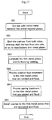
- FIG. 18 is a perspective view of an axis seal (referred as a "leaf seal” hereafter).
- the leaf seal 9A shown in FIG. 18 consists of a housing 92 which is arranged outside of a rotating axis 91 so as to surround the rotating axis 91; a low pressure side plate 93 which is mounted on the lower side of gas pressure of the housing 92; a high pressure side plate 94 which is mounted opposite to the low pressure side plate 93 and on the higher side of gas pressure; and thin metal plates 95.
- the thin metal plates 95 are fitted and engaged into the housing 92 and laminated to the housing 92 in a ring shape. Additionally, the thin metal plates 95 separate the clearance space surrounding the rotation axis 91 into a high-pressure region and a low-pressure region by sealing the periphery of the rotation axis 91. Moreover, on both sides of the thin metal plates 95 are the high-pressure side plate 94 mounted in the high-pressure region and the low-pressure side plate 93 mounted in the low-pressure region, each of which is mounted as a guide plate in a pressure-acting direction.
- the thin metal plates 95 are designed so as to have a predetermined rigidity, which is determined by the thickness of the plate, in a circumferential direction of the rotation axis 91. Additionally, the thin metal plates 95 are mounted to the housing 92 in a manner that an angle made with the circumferential surface of the rotation axis 91 is to be an acute angle against the rotation direction of the rotation axis 91. When the rotation axis 91 stops, the tips of the thin metal plates 95 are in contact with the rotation axis 91 by a predetermined preload. However, when the rotation axis 91 rotates, the thin metal plates 95 and the rotation axis 91 are not in contact with each other because the tips of the thin metal plates 95 are raised by an effect of dynamic pressure caused by rotation of the rotation axis 91.
- FIG. 19A and FIG. 19B show the front view and the side view of the thin metal plate 95 respectively.
- the portion 95d indicated with halftone dot meshing in FIG. 19B is a portion, which is to be eliminated by etching when the thin metal plate 95 is manufactured.
- the portions 95d to be eliminated by etching become a clearance space between the thin metal plates 95.
- the end portions 951 on the periphery of the thin metal plates 95 are arranged to be in contact with each other, while the end portions 952 on the opposite side of the end portion 951 are arranged so as not to be in contact.
- the thin metal plates 95 having a width in the axial direction of the rotation axis 91 are laminated in a multiple number of layers in the circumferential direction of the rotation axis 91, these thin metal plates 95 have soft flexibility for the rotation axis 91 in the circumferential direction, and an axis sealing mechanism having high rigidity is constructed in the axial direction.
- the thin metal plate 95 is formed so as to obtain the predetermined shape by etching a steel plate, which is formed by rolling. At this time, only one side of the thin metal plate 95 is partially etched to be eliminated. However, in case of a thin plate of metal material (e.g. stainless, Inconel, Hastelloy and the like) of approximately 0.1 mm thickness manufactured by rolling, as shown in FIG. 19B, large residual stress (strain) occurs inside the metal material at the time of cold rolling.
- metal material e.g. stainless, Inconel, Hastelloy and the like
- a multiple number of thin metal plates 95 are used for a leaf seal 9A.
- the leaf seal 9A has portions containing non-uniform space generated here and there, and in these portions, a flow of gas occurs, whereby airtightness of seal is sometimes lost.
- the thin metal plates 95 warp in a direction opposite to the rotating direction of the rotation axis and the like facing to the seal 9A, there arises a possibility of the thin metal plates' 95 contacting with a rotation axis and the like due to shaft vibration during initiation of rotation or during a transition period of rotation such as stopping and the like, or due to a transient thermal deformation.
- the present invention seeks to provide a rotary machine using an axis seal which has a stable characteristic of seal, thereby showing a stable performance thereof, and at the same time does not reduce mechanical efficiency thereof significantly without changing the axis seal for a long time.
- a method of manufacturing an axis seal formed by laminating axis seal members of thin films having flexibility so as to be in a shape of a ring wherein, it is characterized by including a cutting process in which a roll of rolled metal material is cut into a predetermined size of a metal material plate; an etching process in which a multiple number of axis seal members of thin metal plates are produced by etching the only one side of the metal material plates that are cut off in the aforementioned cutting process, so as to thin them and provide them with a difference in level; a welding process in which the thin metal plates formed by etching in the aforesaid manner are arranged so as to be in a ring shape and to be oriented in the same direction, and are welded to the casing to be fixed; and the heat treatment process in which residual stresses are eliminated by heating the metal materials or the axis seal members.
- an axis seal member constructing an axis seal which is manufactured by a method of manufacturing an axis seal including heat treatment processes inserted at an appropriate step between a plurality of processes and which seals a flow in an axial direction of the rotation axis; wherein, an axis seal member is characterized by being a flat plate having no strain or almost having no strain.
- an axis seal which is manufactured by a method of manufacturing an axis seal including heat treatment processes inserted at an appropriate step between a plurality number of processes and which seals a flow in an axial direction of the rotation axis; an axis seal which is characterized by: wherein, the axis seal members are formed so as to have no strain or to almost have no strain and are laminated in a ring shape; wherein the axis seal members are arranged so as to contact the rotation axis when the rotation axis stops; and wherein, the tips of the axis seal members slightly rise from the rotation axis due to dynamic pressure caused by rotation when the rotation axis rotates.
- a rotary machine having an axis seal which separates the space surrounding the rotation axis into the high pressure region and the low pressure region; a rotary machine using an axis seal which is characterized by: wherein, the axis seal is configured in a manner that a multiple number of axis seal members are laminated in a ring shape; wherein, axis seal members are manufactured by a method of an axis seal including heat treatment processes at an appropriate step between a plurality number of manufacturing processes of an axis seal; and wherein, the axis seal members are flat plates having no strain or almost having no strain.
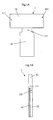
- FIG. 1A is a front view and FIG. 1B is a side view of a thin metal plate of an axis seal member in accordance with the embodiment of the present invention.
- FIG. 2A is a side view of an axis seal (referred as a "leaf seal" hereinafter) in accordance with the embodiment of the present invention, wherein a portion is partially cut off.
- FIG. 2B is a cross-sectional drawing of a leaf seal in accordance with the embodiment of the present invention.
- FIG. 2C is a side view of a leaf seal shown in FIG. 2B when the housings and the side plates thereof are removed.
- FIG. 2D is a side view of a leaf seal in accordance with the embodiment of the present invention when it is in a state of working.
- a thin metal plate 1 has an edge portion 11 on the upper side in the figure (on the side of the periphery thereof when it is formed as a leaf seal) formed so as to be laterally long. Also, as shown in FIG. 1B, a tip 12 of the thin metal plate 1 on the lower side in the figure is formed to be thinner than the remaining portions by having one side eliminated.
- the thin metal plate 1 has a connecting portion 121 of the tip 12 to the edge portion 11 on the periphery formed to be of more slender than the remaining portions. After a plurality number of thin metal plates 1 are laminated and fixed by welding, a tip 211 of a side plate 21 which will be described hereinafter is fit to the slender portion 121.
- a portion 1d indicated with halftone dot meshing is a portion to be eliminated by etching while manufacturing of the above-mentioned thin metal plate 1.
- the portion 1d to be eliminated by etching becomes a clearance space between the thin metal plates 1.
- the edge portions 11 on the periphery of the thin metal plates 1 are arranged so as to contact with each other, whereas the tips 12 on the opposite side are arranged so as not to be in contact.
- the leaf seal A shown in FIG. 2A through FIG. 2D is equipped with a thin metal plate 1 in a letter "T" viewed from the top; housings 2 catching the edge portion 11 on the periphery of a multiple number of laminated thin metal plates 1 from both sides; side plates 21 arranged along the tip 12 in the lower part of the housings 2; and a connection member 22 connecting the housings 2 on the right and on the left.
- the thin metal plates 1 are fixed to each other by welding Wd of both sides 111 and 111 of the edge portions 11 on the upper side of the thin metal plates 1 (on the periphery side when the thin metal plates 1 are formed as a leaf seal). Then, the tips 211 of side plates 21 are arranged in a manner that the slender portions 121 of the tips 12 of the thin metal plates 1 fixed by welding are fit to the tips 211 of side plates 21. (See FIG. 2B.)
- the housings 2 are installed so as to catch in the both sides 111 and 111 of the edge portions 11, when the lower edges 2d of the housings 2 are pressing the tips 211 of the side plates 21 from the outside. Additionally, the housings 2 support the thin metal plates 1 by arranging the connection member 22 between the upper edge portions 2u on both right and left sides and fixing them with a fixing method which does not give an adverse effect to an action of the leaf seal. Welding, bolting and the like, although not limited to, are among methods of fixing the housings 2, the side plates 21 and the connection member 22.
- the thin metal plates 1 laminated in a multiple number of layers are arranged so as to have the edge portions 11 on the upper side thereof get contact with each other and are fixed. However, in the tips 12, a portion thereof, which is thinner than the remaining portion, acts as a clearance gap.
- a clearance gap 1G has a uniform size at any location. (See FIG. 2A and FIG. 2C.)
- a thin metal plate 1 is designed so as to have a predetermined rigidity, which is determined by plate thickness t, in a circumferential direction of a rotation axis Sp. Also, thin metal plates 1 are installed to the housings 2 in a manner that the angle ⁇ made with a phase of the rotation axis Sp in the rotation direction of the rotation axis Sp is an acute angle.
- the tips 12 of the thin metal plates 1 are in contact with the rotation axis Sp due to a predetermined preload; whereas, when the rotation axis Sp rotates, the tips 12 of the thin metal plates 1 rise upward due to dynamic effect caused by rotation of the rotation axis Sp, thereby causing the thin metal plates 1 not to be in contact with the rotation axis Sp.
- the seal leaf A divides a space surrounding the rotation axis Ap into a high-pressure region and a low-pressure region by sealing the periphery of the rotation axis Sp.
- This leaf seal A makes the periphery side thereof to be fixed to the housings 2 be rigid in an axial direction of the rotation axis Sp by laminating the thin metal plates 1 of sealing members in an axial direction of the rotation axis Sp, thereby making it possible to maintain sealing performance under condition of higher differential pressure. Additionally, existence of the clearance gap 1G provides advantages that seal is not broken during rotation and that durability is high.
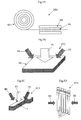
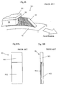
- FIG. 3 shows a layout of a gas turbine which is a rotary machine using a leaf seal shown in FIG. 2A through FIG. 2D.
- a gas turbine Gt shown in FIG. 3 comprises a compressor 3 which takes in a multiple amount of air inside thereof and compresses it; a combustor 4 which mixes the air compressed by the compressor 3 with fuel and burns it; a turbine 5 which is rotated by combustion gas by introducing the combustion gas generated in the combustor 4 into the inside thereof and expanding it threin; and a rotation axis 6 which is fixed relatively to the turbine 5.
- the gas turbine Gt generally utilizes a part of power, which is obtained by the rotation axis, as a power of the compressor 3.
- the turbine 5 converts the thermal energy of combustion gas into the kinetic rotational energy by blowing combustion gas to rotating blades 51 installed to the rotation axis 6 and generates the power.
- the turbine 5 is equipped with a plurality number of stationary vanes 52 that are mounted mounted to a casing 50 of the turbine 5 as well as with a plurality number of rotating blades 51 mounted to the rotation axis 6, and these rotating blades 51 and stationary vanes 52 are arranged alternately in an axial direction of the rotation axis 6.
- the rotating blades 51 rotate the rotation axis 6 by receiving pressure of the combustion gas flowing in an axial direction of the rotation axis 6, and the rotational energy supplied to the rotation axis 6 is taken out from the end of the axis and used.
- a leaf seal A as an axis seal for a purpose of reducing the amount of combustion gas leaking from the high pressure side to the low pressure side.
- the compressor 3 is connected coaxially to the turbine 5 by the rotation axis 6 and compresses fresh air by utilizing rotation of the turbine 5 so as to supply compressed air to the combustor 4.
- the compressor 3 has a plurality number of rotating blades 31 mounted to the rotation axis 6 and a plurality number of stationary vanes 32 mounted to a casing 30 of the compressor 3 in the same manner as the turbine 5 and has the rotating blades 31 and the stationary vanes 32 arranged alternately in an axial direction of the rotation axis 6.
- a leaf seal A Between the stationary vanes 32 and the rotation axis 6 is installed a leaf seal A for a purpose of reducing the amount of compressed air leaking from the high pressure side to the low pressure side.
- a bearing portion 33 in which the casing 30 of the compressor 3 supports the rotation axis 6 and a bearing portion 53 in which the casing 50 of the turbine 5 supports the rotation axis 6 have a leaf seal A installed thereon as an axis seal to prevent compressed air or combustion gas from leaking from the high pressure side to the low pressure side.
- the axis seal and the gas turbine constructed as mentioned above have thin metal plates 1 having a width thereof in an axial direction of the rotation axis Sp are laminated in a multiple number of layers in a circumferential direction of the rotation axis Sp, wherein the thin metal plates 1 have soft flexibility in a circumferential direction of the rotation axis Sp, whereas constituting an axis seal having high rigidity in an axial direction.
- a leaf seal is not limited to this adoption but can be adopted widely to what can convert an energy into a duty due to a relation between the rotation of an axis and the flow of a fluid, for example, to a steam turbine, a compressor and the like.
- a leaf seal can be used to restrain the flow of a fluid in an axial direction of a rotation axis as well.
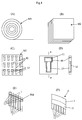
- FIG. 4 shows processes of manufacturing a thin metal plate from a metal material plate.
- a plurality number of thin metal plates 1 are manufactured from metal material plates by etching.
- a roll of rolled metal material M1 is cut out into an optimum size to be subject to the following processing step so as to form a predetermined size of metal material plates M2.
- Outline portions 10 of thin metal plates 1 and tips 12 of the thin metal plates 1, which are to be a clearance gap 1d when the leaf seal A is assembled, are eliminated by etching from a first surface of the metal material plates M2.
- the thin metal plates 1 shown in FIG. 4 (E) are laminated in a ring shape with the portions 1d eliminated by etching, heading for the same direction, and have both sides of the upper edge portions 11 extending to right and left welded, thereby fixing the thin metal plates 1 to each other.
- the thin metal plates 1 which are laminated so as to orient to the same direction and welded have the upper edge portions 11 thereof fit and engaged into the housings 2 on both sides, and by fixing the both sides of the housings 2 mutually, the laminated thin metal plates 1 are fixed. (See (F).)
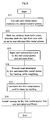
- FIG. 5 shows a process of heat treatment in accordance with the embodiment of the present invention.
- a roll of rolled metal M1 is expanded by being transmitted at a predetermined speed and is heated with a heating equipment HS, thereby removing residual stress (strain). Since heating H1 with the heating equipment HS is included as a part of a process, wherein a roll of rolled metal M1 is expanded and cut out into metal material plates M2 and since a volume of the metal M1 is small whereby holding time is reduced to be short, it is possible to shorten the production process.
- a heat treatment method HT2 shown in FIG. 5B residual stress (strain) is eliminated by laminating the metal material plates M2 so as to be subject to weighting with P1 (dead weight + weight) and heating H2.
- This method can use an existing ordinary electric furnace, achieving a low cost.
- laminated thin plates provide relatively uniform temperature distribution during heat treatment and during post-heat-treatment cooling, deformation of the thin plates after heat treatment, especially deformation at the edge portions due to non-uniform cooling, is small, thereby obtaining a material of good quality, having good flatness.
- a heat treatment method HT3 shown in FIG. 5C by etching the metal material plates M2 after a plurality number of thin metal plates 1 are manufactured and by laminating the thin metal plates 1 and heating H3 them while weighting with P2 (dead weight + weight), residual stress (strain) is eliminated. Since the thin metal plates 1 are small, there is an advantage that a heating equipment becomes smaller.
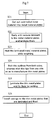
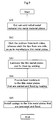
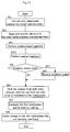
- FIG. 6 shows a flow chart of a manufacturing process of an axis seal in accordance with an embodiment of the present invention.
- a leaf seal A manufactured by a manufacturing process shown in FIG. 6 is an axis seal which seals low temperature fluid, and although not limited to this leaf seal, a leaf seal A is formed of stainless steel.
- a metal formed by cold rolling so as to obtain a predetermined thickness has residual stress (strain) accumulated inside thereof. Therefore, in order to eliminate the residual stress (strain), heat treatment (heating at 740°C for 30 minutes and then cooling) is performed by transmitting a roll of rolled metal material M1 little by little. (See FIG. 5A.) (Step S11)
- Step S12 From the cut-out metal material plate M2, thin metal plates 1 are manufactured by etching the outline portions 10 from both sides and by etching the tips 12 from one side.
- Step S13 A plurality number of the thin metal plates 1 manufactured in Step S13 are laminated so as to orient to the same direction and to be in a ring shape and are fixed to each other by welding both right and left sides 111 and 111 of the upper edge portions 11.
- Step S14 After fixing a plurality number of the thin metal plates 1 in laminated state, the upper edge portions are fixed with the housings 2, the side plates 21 and the connection member 22 (Step S15), thus manufacturing a leaf seal.
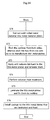
- FIG. 7 shows a flow chart of a manufacturing process of an axis seal in accordance with an embodiment of the present invention.
- a roll of rolled metal material M1 is cut out into predetermined size of metal material plates M2 to be suitable for processing.
- Step S21 A plurality number of the metal material plates M2 that are cut out into a predetermined size in Step S21 are arranged so as to be piled up, when anti-seizure lubricant is applied to spaces between the metal material plates M2.
- Step S22 Thereafter, the metal material plates M2 laminated in Step S22 are heated (at 680°C for four hours), weighting, whereby residual stress (strain) is eliminated from the metal material plates M2. (See FIG. 5B.)
- Step S23 A plurality number of the metal material plates M2 that are cut out into a predetermined size in Step S21 are arranged so as to be piled up, when anti-seizure lubricant is applied to spaces between the metal material plates M2.
- Step S22 There
- the thin metal plates 1 are manufactured by having the portions of the metal material plates M2 which correspond to the outline portions 10 of the thin metal plates 1 etched from both sides and by having portions corresponding to the tips 12 etched from one side.
- Step S24 A plurality number of the thin metal plates 1 manufactured in Step S24 are laminated so as to orient to the same direction and to be in a ring shape and are fixed to each other by welding both right and left sides 111 and 111 of the upper edge portions 11.
- Step S25 After fixing a plurality number of the thin metal plates 1 in laminated state, the upper edge portions thereof are fixed with the housings 2, the side plates 21 and the connection member 22 (Step S26), thus manufacturing a leaf seal.
- Manufacturing in the above-mentioned manner makes it possible to use an existing ordinary electric furnace, achieving low cost.
- the laminated thin plates provide a relatively uniform temperature distribution during heat treatment and during post-heat-treatment cooling, deformation of the thin plates after heat treatment, especially deformation at the edge portions due to non-uniform cooling, is small, thereby obtaining a metal material plates M2 of good quality having good flatness. Since this method is subject to batch processing, it is effective in case of a relatively small number of treatment.
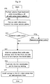
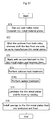
- FIG. 8 shows a flow chart of a manufacturing process of an axis seal in accordance with an embodiment of the present invention.
- a roll of rolled metal material M1 is cut out into a predetermined size of metal material plates M2 to be suitable for processing.
- Thin metal plates 1 are manufactured by having the portions of the metal material plates M2 cut out in Step S31 that correspond to the outline portions 10 of the thin metal plates 1 etched from both sides and by having the portions corresponding to the tips 12 etched from one side.
- the thin metal plates 1 formed in Step S32 are laminated so as to orient to a predetermined direction.
- the thin metal plates 1 piled up in Step S33 are heated (at 680°C for four hours), weighting, thereby eliminating residual stress (strain) from the thin metal plates. (See FIG. 5C.)
- Step S34 Step S34
- Step S35 After fixing a plurality number of the thin metal plates 1 in laminated state, the upper edge portions thereof are fixed with the housings 2, the side plates 21 and the connection member 22 (Step S36), thus manufacturing a leaf seal A.
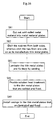
- FIG. 9 shows a flow chart of a manufacturing process of an axis seal in accordance with an embodiment of the present invention.
- a roll of rolled metal material M1 is cut out into predetermined size of metal material plates M2 to be suitable for processing.
- Thin metal plates 1 are manufactured by having the portions of the metal material plates M2 cut out in Step S41 which correspond to the outline portions 10 of the thin metal plates 1 etched from both sides and by having the portions corresponding to the tips 12 etched from one side as mentioned above.
- Step 42 is
- Step S43 After being fixed in Step S43, the thin metal plates 1 in lamination layers are heated (at 680°C for four hours) so as to eliminate residual stress (strain) which is accumulated inside of the thin metal plates 1. (See FIG. 5D.)
- Step S44 Thereafter, the upper edge portions are fixed with the housings 2, the side plates 21 and the connection member 22 (Step S45), thus manufacturing a leaf seal.
- the above embodiments are methods of manufacturing axis seals to be used where fluid of relatively low temperature (up to approximately 400°C) is handled.
- the above-mentioned four methods are examples of manufacturing methods of a leaf seal, but not limited to.
- Temperature and time of heat treatment are not limited to the above, but it is possible to adopt manufacturing methods widely that can release residual stress (strain) accumulated on a metal plate.
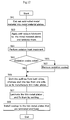
- FIG. 10 shows a flow chart of a manufacturing process of an axis seal in accordance with an embodiment of the present invention.
- An axis seal A manufactured in a manufacturing process shown in FIG. 10 is an axis seal which seals fluid of relatively high temperature (for example, more than 400°C), and although not limited to, an axis seal is to consist of Inconel material herein.
- Rolls of rolled metal materials that are formed by cold rolling so as to have a predetermined thickness have residual stress (strain) accumulated inside thereof. In order to eliminate the residual stress (strain), solution heat treatment is performed by transmitting rolls of rolled metal materials M1 little by little. (See FIG.
- Step S51 Solution heat treatment is a treatment, wherein a metal is held at a predetermined temperature for a predetermined time and subsequently, by cooling the metal rapidly, alloy elements and deposits are solved into matrix. Temperature and time conditions at this time are 980°C and 30 minutes herein, but not limited to. Subsequently, a roll of cold-rolled metal material M1 is cut out into a predetermined size so as to be easy for processing. (Step S52)
- Step S53 In case of presence of oxidation scales (in case of YES in Step S53), oxidation scales are removed by soaking the metal material plates into an acid or alkali liquid. (Step S54)
- Step S55 A plurality number of the thin metal plates 1 manufactured in Step S55 are laminated so as to orient to the same direction and to be in a ring shape and are fixed to each other by welding both right and left sides 111 and 111 of the upper edge portions thereof.
- Step S56 After a plurality number of thin metal plates 1 are fixed in laminated state by welding, the upper edge portions thereof are fixed with the housings 2, the side plates 21 and the connection member 22 (Step S57), thus manufacturing a leaf seal.
- a treatment as an ageing treatment (Step S511), may be included; wherein, after solution heat treatment (Step S51), the roll of rolled metal material M1 are held at 732°C for eight hours; wherein the temperature is decreased down to 621°C, at which the thin metal plates are held for ten hours; and wherein, the thin metal plates are cooled.
- solution heat treatment it is possible or it is almost possible to eliminate residual stress (strain).
- ageing treatment makes it possible to eliminate residual stress (strain) and to obtain strength at high temperature as well.
- a method is exemplified that acid or alkali liquid is used for washing in order to get rid of oxidation scales, but not limited to, and mechanical grinding with a grinder, for example, can be used. Also, it is not limited to the above-mentioned means, but it is possible to adopt means widely that can eliminate oxidation scales so as not to let them remain on the surfaces which are subject to etching.
- FIG. 12 shows a flow chart of a manufacturing process of an axis seal in accordance with an embodiment of the present invention.
- a roll of rolled metal material M1 is cut out into predetermined size of metal material plates M2.
- Step S61 A plurality number of metal material plates M2 cut out into a predetermined size in Step S61 are arranged so as to be piled up each other, when anti-seizure lubricant is applied to the space between the metal material plates M2.
- Step S62 Thereafter, by heating the metal material plates M2 laminated in Step S62 (at 982°C for 30 minutes), solution heat treatment is supplied so as to eliminate residual stress (strain) from the metal material plates. (See FIG. 5B.)
- Step S63 Step S63
- Step S64 In case of occurrence of oxidation scales (in case of YES in Step S64), oxidation scales are got rid of by soaking the metal material plates M2 in acid or alkali liquid. (Step S65)
- Step S66 A plurality number of thin metal plates 1 manufactured in Step S66 are laminated so as to orient to the same direction and to be in a ring shape and are fixed to each other by welding both right and left sides 111 and 111 of the upper edge portions 11 thereof.
- Step S67 After fixing a plurality number of thin metal plates 1 in laminated state, the upper edge portions thereof are fixed with the housings 2, the side plates 21 and the connection member 22 (Step S68), thereby manufacturing a leaf seal.
- a treatment as an ageing treatment (Step S631), may be included; wherein, after solution heat treatment (Step S63), thin metal plates are held at 732°C for eight hours; wherein, subsequently, the temperature is decreased down to be 621°C, at which the thin metal plates are held for ten hours; and wherein, the thin metal plates are cooled.
- solution heat treatment it is possible or it is almost possible to eliminate residual stress (strain).
- ageing treatment makes it possible to eliminate residual stress (strain) and to obtain strength at high temperature as well.
- a method is exemplified that acid or alkali liquid is used for washing in order to get rid of oxidation scales, but not limited to, and mechanical grinding with a grinder, for example, may be used. Also, it is not limited to the above-mentioned means, but it is possible to adopt means widely that can eliminate oxidation scales so as not to let them remain on the surfaces which are subject to etching.
- FIG. 14 shows a flow chart of a manufacturing process of an axis seal in accordance with an embodiment of the present invention.
- a roll of rolled metal material M1 is cut out into a predetermined size of metal material plates M2 to be suitable for processing.
- the portions corresponding to the outline portions of the thin metal plates 1 are etched from both sides and the portions corresponding to the tips 12 thereof are etched from one side, as mentioned above, thereby manufacturing thin metal plates 1.
- Step S72 A plurality number of thin metal plates 1 manufactured in Step S72 are arranged so as to be piled up, when anti-seizure lubricant is applied to the space between the metal plates.
- Step S73 the thin metal plates 1 laminated in Step S73 are heated (at 982°C for 30 minutes) so as to be provided with solution heat treatment, thereby getting rid of residual stress (strain) from the metal plates . (See FIG. 5C.) (Step S74)
- Step S72 a plurality number of thin metal plates 1 which are manufactured in Step S72 and have residual stress (strain) eliminated in Step S74 are laminated so as to orient to the same direction and to be in a ring shape, and the thin metal plates 1 are fixed to each other by welding both right and left sides 111 and 111 of the upper edge portions 11 thereof.
- Step S75 After fixing a plurality number of thin metal plates 1 in laminated state, the upper edge portions thereof are fixed with the casings 2, the side plates 21 and the connection member 22 (Step S76), thus manufacturing a leaf seal.
- a treatment as an ageing treatment (Step S741), may be included; wherein, after solution heat treatment (Step S74), thin metal plates are held at 732°C for eight hours; wherein, subsequently, the temperature is decreased down to be 621°C, at which the thin metal plates are held for ten hours; and wherein, the thin metal plates are cooled.
- solution heat treatment it is possible or it is almost possible to eliminate residual stress (strain).
- ageing treatment makes it possible to eliminate residual stress (strain) and to obtain strength at high temperature as well.
- a method is exemplified that acid or alkali liquid is used for washing in order to get rid of oxidation scales, but not limited to, and mechanical grinding with a grinder, for example, can be used. Also, it is not limited to the above-mentioned means, but it is possible to adopt means widely that can eliminate oxidation scales so as not to let them remain on the surfaces which are subject to etching.
- FIG. 16 shows a flow chart of a manufacturing process of an axis seal in accordance with an embodiment of the present invention.
- a roll of rolled metal material M1 is cut out into predetermined size of metal material plates M2 to be suitable for processing.
- the cut-out metal material plates M2 have the portions corresponding to the outline portions 10 of the thin metal plates 1 etched from both sides and have the portions corresponding to the tips 12 etched from one side, mentioned above, thereby manufacturing the thin metal plates 1.
- Step S82 A plurality number of thin metal plates 1 manufactured in Step S82 are laminated so as to orient to the same direction and to be in a ring shape, and the thin metal plates 1 are fixed to each other by welding both right and left sides 111 and 111 of the upper edge portions 11 thereof.
- Step S83 The thin metal plates 1 welded and fixed in Step S83 are heated (at 982°C for 30 minutes) so as to be provided with solution heat treatment, thereby getting rid of residual stress (strain) from the metal plates . (See FIG. 5D.) (Step S84)
- Step S83 the thin metal plates 1, which are welded and fixed in a ring shape in Step S83 and have residual stress eliminated in Step S84, have the upper edge portions 11 thereof fixed with the housings 2, the side plates 21 and the connection member 22 (Step S85), thereby manufacturing a leaf seal.
- a treatment may be included; wherein, after solution heat treatment (Step S84), thin metal plates 1 are held at 732°C for eight hours as an ageing treatment (Step S841); wherein, subsequently, the temperature is decreased down to be 621°C, at which the thin metal plates are held for ten hours; and wherein, the thin metal plates are cooled.
- solution heat treatment it is possible or it is almost possible to eliminate residual stress (strain).
- ageing treatment makes it possible to eliminate residual stress (strain) and to obtain strength at high temperature as well. Additionally, since heat treatment is performed after welding, it is also possible to get rid of residual stress caused by welding.
- a method is exemplified that acid or alkali liquid is used for washing in order to get rid of oxidation scales, but not limited to, and it is possible to adopt means widely that can eliminate oxidation scales so as not to have them remain on the surfaces which are subject to etching.
- metal material plates are formed by cold rolling method, but not limited to, and it is possible to widely adopt a method that can stretch and roll a metal material plate to be thin.
Landscapes
- Engineering & Computer Science (AREA)
- General Engineering & Computer Science (AREA)
- Mechanical Engineering (AREA)
- Gasket Seals (AREA)
- Sealing Devices (AREA)
- Turbine Rotor Nozzle Sealing (AREA)
- Structures Of Non-Positive Displacement Pumps (AREA)
Abstract
Description
- The present invention relates to a method of manufacturing axis seals which restrain a flow of fluid in a direction of the rotation axis of a rotary machine such as a gas turbine and the like, axis seals, axis seal members and rotary machines using the axis seals.
- A gas turbine which leads high temperature and high pressure gas to a turbine and expands it so as to generate motive power by converting the thermal energy of gas to kinetic rotational energy has a sealing mechanism (an axis seal) mounted thereto between the stationary vanes and the rotation axis in order to reduce an amount of high temperature and high pressure gas leaking from the high pressure side to the low pressure side. Conventionally, non-contact types of labyrinth seals are widely used as the sealing mechanism.
- In the labyrinth seals, the amount of leaking gas is large because the clearance space at the tip of a fin must be made large to some extent in order that the tip of the fin will not come into contact during shaft vibration in the transient period of rotation or during transient time of thermal deformation. Leaf seals are developed to take the place of labyrinth seals as mentioned above, aiming at reduction in the leaking amount.
- FIG. 18 is a perspective view of an axis seal (referred as a "leaf seal" hereafter). The
leaf seal 9A shown in FIG. 18 consists of ahousing 92 which is arranged outside of a rotatingaxis 91 so as to surround therotating axis 91; a lowpressure side plate 93 which is mounted on the lower side of gas pressure of thehousing 92; a highpressure side plate 94 which is mounted opposite to the lowpressure side plate 93 and on the higher side of gas pressure; andthin metal plates 95. - The
thin metal plates 95 are fitted and engaged into thehousing 92 and laminated to thehousing 92 in a ring shape. Additionally, thethin metal plates 95 separate the clearance space surrounding therotation axis 91 into a high-pressure region and a low-pressure region by sealing the periphery of therotation axis 91. Moreover, on both sides of thethin metal plates 95 are the high-pressure side plate 94 mounted in the high-pressure region and the low-pressure side plate 93 mounted in the low-pressure region, each of which is mounted as a guide plate in a pressure-acting direction. - The
thin metal plates 95 are designed so as to have a predetermined rigidity, which is determined by the thickness of the plate, in a circumferential direction of therotation axis 91. Additionally, thethin metal plates 95 are mounted to thehousing 92 in a manner that an angle made with the circumferential surface of therotation axis 91 is to be an acute angle against the rotation direction of therotation axis 91. When therotation axis 91 stops, the tips of thethin metal plates 95 are in contact with therotation axis 91 by a predetermined preload. However, when therotation axis 91 rotates, thethin metal plates 95 and therotation axis 91 are not in contact with each other because the tips of thethin metal plates 95 are raised by an effect of dynamic pressure caused by rotation of therotation axis 91. - FIG. 19A and FIG. 19B show the front view and the side view of the
thin metal plate 95 respectively. Theportion 95d indicated with halftone dot meshing in FIG. 19B is a portion, which is to be eliminated by etching when thethin metal plate 95 is manufactured. When thethin metal plates 95 are laminated, theportions 95d to be eliminated by etching become a clearance space between thethin metal plates 95. In other words, theend portions 951 on the periphery of thethin metal plates 95 are arranged to be in contact with each other, while theend portions 952 on the opposite side of theend portion 951 are arranged so as not to be in contact. - In an axis sealing mechanism and a gas turbine that are constructed as described above, since the
thin metal plates 95 having a width in the axial direction of therotation axis 91 are laminated in a multiple number of layers in the circumferential direction of therotation axis 91, thesethin metal plates 95 have soft flexibility for therotation axis 91 in the circumferential direction, and an axis sealing mechanism having high rigidity is constructed in the axial direction. - By having the space between the
thin metal plates 95 made by theportions 95d where thin metal plates are eliminated, it is possible to arrange thethin metal plates 95 more closely and it is also possible to make the space between the tips of thethin metal plates 95 and therotation axis 91 significantly small, compared with non-contact type of labyrinth seals and the like, whereby it is possible to reduce the amount of leaking gas to be approximately 1/3 to 1/10 of that of labyrinth seals. - The
thin metal plate 95 is formed so as to obtain the predetermined shape by etching a steel plate, which is formed by rolling. At this time, only one side of thethin metal plate 95 is partially etched to be eliminated. However, in case of a thin plate of metal material (e.g. stainless, Inconel, Hastelloy and the like) of approximately 0.1 mm thickness manufactured by rolling, as shown in FIG. 19B, large residual stress (strain) occurs inside the metal material at the time of cold rolling. - When such a material having a large residual stress (strain) inside thereof as described above is thinned by etching only one side thereof in an above-mentioned manner, the distribution of residual stress (strain) becomes non-uniform, causing bending or warp.
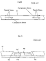
- For example, as shown in FIG. 20, when assumed tensile stresses are formed on both surfaces of a cold-rolled material and assumed compressive stresses are formed inside thereof, as a whole, the residual stresses on the surface and the residual stresses inside thereof will balance, maintaining the plane. However, as shown in FIG. 21, when a
portion 950 of the surface on one side of thethin metal plate 95 is eliminated by etching, residual stresses remain in thecentral portion 95C and on thesurface 95S, excluding the eliminatedportion 950. Therefore, by having compressive stress acting on one side (in thecentral portion 95C) while having tensile stress acting on the other side (on thesurface portion 95S), bendingmoments 9M occur, whereby thethin metal plate 95 warps in a direction toward the eliminatedportion 950. - A multiple number of
thin metal plates 95 are used for aleaf seal 9A. By having thethin metal plates 95 warped due to residual stress, theleaf seal 9A has portions containing non-uniform space generated here and there, and in these portions, a flow of gas occurs, whereby airtightness of seal is sometimes lost. - Additionally, since the
thin metal plates 95 warp in a direction opposite to the rotating direction of the rotation axis and the like facing to theseal 9A, there arises a possibility of the thin metal plates' 95 contacting with a rotation axis and the like due to shaft vibration during initiation of rotation or during a transition period of rotation such as stopping and the like, or due to a transient thermal deformation. - It is an object of the present invention to provide a method of manufacturing an axis seal which seals by laminating a plurality number of thin metal plates into a shape of a ring and to provide a method of an manufacturing axis seal, in order to manufacture an axis seal which has a smaller amount of leaking gas, compared with an axis seal which uses conventional thin metal plates.
- It is another object of the present invention to provide an axis seal, which can be assembled easily and can attempt to reduce the amount of leaking gas, in other words, to stabilize the characteristic of seal.
- Furthermore, the present invention seeks to provide a rotary machine using an axis seal which has a stable characteristic of seal, thereby showing a stable performance thereof, and at the same time does not reduce mechanical efficiency thereof significantly without changing the axis seal for a long time.
- In order to achieve the above-mentioned objects, according to the present invention, there is provided a method of manufacturing an axis seal formed by laminating axis seal members of thin films having flexibility so as to be in a shape of a ring; wherein, it is characterized by including a cutting process in which a roll of rolled metal material is cut into a predetermined size of a metal material plate; an etching process in which a multiple number of axis seal members of thin metal plates are produced by etching the only one side of the metal material plates that are cut off in the aforementioned cutting process, so as to thin them and provide them with a difference in level; a welding process in which the thin metal plates formed by etching in the aforesaid manner are arranged so as to be in a ring shape and to be oriented in the same direction, and are welded to the casing to be fixed; and the heat treatment process in which residual stresses are eliminated by heating the metal materials or the axis seal members.
- In a preferred embodiment according to the present invention, there is provided an axis seal member constructing an axis seal which is manufactured by a method of manufacturing an axis seal including heat treatment processes inserted at an appropriate step between a plurality of processes and which seals a flow in an axial direction of the rotation axis; wherein, an axis seal member is characterized by being a flat plate having no strain or almost having no strain.
- In a further preferred embodiment according to the present invention, there is provided an axis seal which is manufactured by a method of manufacturing an axis seal including heat treatment processes inserted at an appropriate step between a plurality number of processes and which seals a flow in an axial direction of the rotation axis; an axis seal which is characterized by:
wherein, the axis seal members are formed so as to have no strain or to almost have no strain and are laminated in a ring shape;
wherein the axis seal members are arranged so as to contact the rotation axis when the rotation axis stops; and
wherein, the tips of the axis seal members slightly rise from the rotation axis due to dynamic pressure caused by rotation when the rotation axis rotates. - In a further preferred embodiment according to the present invention, there is provided a rotary machine having an axis seal which separates the space surrounding the rotation axis into the high pressure region and the low pressure region; a rotary machine using an axis seal which is characterized by:
wherein, the axis seal is configured in a manner that a multiple number of axis seal members are laminated in a ring shape;
wherein, axis seal members are manufactured by a method of an axis seal including heat treatment processes at an appropriate step between a plurality number of manufacturing processes of an axis seal; and
wherein, the axis seal members are flat plates having no strain or almost having no strain. -
- FIG. 1A is a front view of a thin metal plate which is an axis seal member in accordance with an embodiment of the prevent invention, and FIG. 1B is a side view of the thin metal plate shown in FIG. 1A.
- FIG. 2A is a side view of an axis seal in accordance with the embodiment of the present invention; FIG. 2B is a cross-sectional view of an axis seal; FIG. 2C is a side view of an axis seal which has housings and side plates removed; and FIG. 2D depicts an action of the axis seal when the axis is rotating.
- FIG. 3 is a layout drawing of a gas turbine.
- FIG. 4 depicts manufacturing processes of an axis seal.
- FIG. 5A through FIG. 5D depict examples of heat treatment processes respectively.
- FIG. 6 is a flow chart of a manufacturing process of an axis seal.
- FIG. 7 is a flow chart of a manufacturing process of an axis seal.
- FIG. 8 is a flow chart of a manufacturing process of an axis seal.
- FIG. 9 is a flow chart of a manufacturing process of an axis seal.
- FIG. 10 is a flow chart of a manufacturing process of an axis seal.
- FIG. 11 is a flow chart of a manufacturing process of an axis seal.
- FIG. 12 is a flow chart of a manufacturing process of an axis seal.
- FIG. 13 is a flow chart of a manufacturing process of an axis seal.
- FIG. 14 is a flow chart of a manufacturing process of an axis seal.
- FIG. 15 is a flow chart of a manufacturing process of an axis seal.
- FIG. 16 is a flow chart of a manufacturing process of an axis seal.
- FIG. 17 is a flow chart of a manufacturing process of an axis seal.
- FIG. 18 is a perspective drawing of an example of a conventional leaf seal.
- FIG. 19A is a top view of a thin metal plate to be used for a leaf seal of a conventional example, and FIG. 19B is a side view of a leaf seal to be used for a leaf seal of a conventional example.
- FIG. 20 depicts a state of stresses on a metal member which is cold rolled.
- FIG. 21 depicts deformation when a portion of a metal member is cut out.
-
- Referring now to the drawings, an embodiment of the present invention will be described hereinafter.
FIG. 1A is a front view and FIG. 1B is a side view of a thin metal plate of an axis seal member in accordance with the embodiment of the present invention. FIG. 2A is a side view of an axis seal (referred as a "leaf seal" hereinafter) in accordance with the embodiment of the present invention, wherein a portion is partially cut off. FIG. 2B is a cross-sectional drawing of a leaf seal in accordance with the embodiment of the present invention. FIG. 2C is a side view of a leaf seal shown in FIG. 2B when the housings and the side plates thereof are removed. FIG. 2D is a side view of a leaf seal in accordance with the embodiment of the present invention when it is in a state of working. - As shown in FIG. 1A and FIG. 1B, a
thin metal plate 1 has anedge portion 11 on the upper side in the figure (on the side of the periphery thereof when it is formed as a leaf seal) formed so as to be laterally long. Also, as shown in FIG. 1B, atip 12 of thethin metal plate 1 on the lower side in the figure is formed to be thinner than the remaining portions by having one side eliminated. - In addition, the
thin metal plate 1 has a connectingportion 121 of thetip 12 to theedge portion 11 on the periphery formed to be of more slender than the remaining portions. After a plurality number ofthin metal plates 1 are laminated and fixed by welding, atip 211 of aside plate 21 which will be described hereinafter is fit to theslender portion 121. - In FIG. 1B, a
portion 1d indicated with halftone dot meshing is a portion to be eliminated by etching while manufacturing of the above-mentionedthin metal plate 1. Whenthin metal plates 1 are laminated, theportion 1d to be eliminated by etching becomes a clearance space between thethin metal plates 1. In other words, theedge portions 11 on the periphery of thethin metal plates 1 are arranged so as to contact with each other, whereas thetips 12 on the opposite side are arranged so as not to be in contact. - The leaf seal A shown in FIG. 2A through FIG. 2D is equipped with a
thin metal plate 1 in a letter "T" viewed from the top;housings 2 catching theedge portion 11 on the periphery of a multiple number of laminatedthin metal plates 1 from both sides;side plates 21 arranged along thetip 12 in the lower part of thehousings 2; and aconnection member 22 connecting thehousings 2 on the right and on the left. - As shown in FIG. 2B and FIG. 2C, after arranging the
thin metal plates 1 in a ring shape along the curved surface, thethin metal plates 1 are fixed to each other by welding Wd of bothsides edge portions 11 on the upper side of the thin metal plates 1 (on the periphery side when thethin metal plates 1 are formed as a leaf seal).
Then, thetips 211 ofside plates 21 are arranged in a manner that theslender portions 121 of thetips 12 of thethin metal plates 1 fixed by welding are fit to thetips 211 ofside plates 21. (See FIG. 2B.) - Thereafter, the
housings 2 are installed so as to catch in the bothsides edge portions 11, when thelower edges 2d of thehousings 2 are pressing thetips 211 of theside plates 21 from the outside. Additionally, thehousings 2 support thethin metal plates 1 by arranging theconnection member 22 between theupper edge portions 2u on both right and left sides and fixing them with a fixing method which does not give an adverse effect to an action of the leaf seal. Welding, bolting and the like, although not limited to, are among methods of fixing thehousings 2, theside plates 21 and theconnection member 22. - The
thin metal plates 1 laminated in a multiple number of layers are arranged so as to have theedge portions 11 on the upper side thereof get contact with each other and are fixed. However, in thetips 12, a portion thereof, which is thinner than the remaining portion, acts as a clearance gap. Aclearance gap 1G has a uniform size at any location. (See FIG. 2A and FIG. 2C.) - A
thin metal plate 1 is designed so as to have a predetermined rigidity, which is determined by plate thickness t, in a circumferential direction of a rotation axis Sp. Also,thin metal plates 1 are installed to thehousings 2 in a manner that the angle made with a phase of the rotation axis Sp in the rotation direction of the rotation axis Sp is an acute angle. When the rotation axis Sp stops, thetips 12 of thethin metal plates 1 are in contact with the rotation axis Sp due to a predetermined preload; whereas, when the rotation axis Sp rotates, thetips 12 of thethin metal plates 1 rise upward due to dynamic effect caused by rotation of the rotation axis Sp, thereby causing thethin metal plates 1 not to be in contact with the rotation axis Sp. (See FIG. 2D.) The seal leaf A divides a space surrounding the rotation axis Ap into a high-pressure region and a low-pressure region by sealing the periphery of the rotation axis Sp. - This leaf seal A makes the periphery side thereof to be fixed to the
housings 2 be rigid in an axial direction of the rotation axis Sp by laminating thethin metal plates 1 of sealing members in an axial direction of the rotation axis Sp, thereby making it possible to maintain sealing performance under condition of higher differential pressure. Additionally, existence of theclearance gap 1G provides advantages that seal is not broken during rotation and that durability is high. - FIG. 3 shows a layout of a gas turbine which is a rotary machine using a leaf seal shown in FIG. 2A through FIG. 2D. A gas turbine Gt shown in FIG. 3 comprises a
compressor 3 which takes in a multiple amount of air inside thereof and compresses it; acombustor 4 which mixes the air compressed by thecompressor 3 with fuel and burns it; aturbine 5 which is rotated by combustion gas by introducing the combustion gas generated in thecombustor 4 into the inside thereof and expanding it threin; and a rotation axis 6 which is fixed relatively to theturbine 5. The gas turbine Gt generally utilizes a part of power, which is obtained by the rotation axis, as a power of thecompressor 3. - The
turbine 5 converts the thermal energy of combustion gas into the kinetic rotational energy by blowing combustion gas torotating blades 51 installed to the rotation axis 6 and generates the power. Theturbine 5 is equipped with a plurality number ofstationary vanes 52 that are mounted mounted to acasing 50 of theturbine 5 as well as with a plurality number ofrotating blades 51 mounted to the rotation axis 6, and theserotating blades 51 andstationary vanes 52 are arranged alternately in an axial direction of the rotation axis 6. Therotating blades 51 rotate the rotation axis 6 by receiving pressure of the combustion gas flowing in an axial direction of the rotation axis 6, and the rotational energy supplied to the rotation axis 6 is taken out from the end of the axis and used. Between thestationary vanes 52 and the rotation axis 6 is installed a leaf seal A as an axis seal for a purpose of reducing the amount of combustion gas leaking from the high pressure side to the low pressure side. - Additionally, the
compressor 3 is connected coaxially to theturbine 5 by the rotation axis 6 and compresses fresh air by utilizing rotation of theturbine 5 so as to supply compressed air to thecombustor 4. Thecompressor 3 has a plurality number ofrotating blades 31 mounted to the rotation axis 6 and a plurality number ofstationary vanes 32 mounted to acasing 30 of thecompressor 3 in the same manner as theturbine 5 and has therotating blades 31 and thestationary vanes 32 arranged alternately in an axial direction of the rotation axis 6. Between thestationary vanes 32 and the rotation axis 6 is installed a leaf seal A for a purpose of reducing the amount of compressed air leaking from the high pressure side to the low pressure side. - Moreover, a bearing
portion 33 in which thecasing 30 of thecompressor 3 supports the rotation axis 6 and a bearingportion 53 in which thecasing 50 of theturbine 5 supports the rotation axis 6 have a leaf seal A installed thereon as an axis seal to prevent compressed air or combustion gas from leaking from the high pressure side to the low pressure side. - The axis seal and the gas turbine constructed as mentioned above, have
thin metal plates 1 having a width thereof in an axial direction of the rotation axis Sp are laminated in a multiple number of layers in a circumferential direction of the rotation axis Sp, wherein thethin metal plates 1 have soft flexibility in a circumferential direction of the rotation axis Sp, whereas constituting an axis seal having high rigidity in an axial direction. - In the embodiment of the present invention mentioned above, an adoption of a leaf seal to a gas turbine is exemplified. However, a leaf seal is not limited to this adoption but can be adopted widely to what can convert an energy into a duty due to a relation between the rotation of an axis and the flow of a fluid, for example, to a steam turbine, a compressor and the like. A leaf seal can be used to restrain the flow of a fluid in an axial direction of a rotation axis as well.
- In FIG. 4, (A) through (F) show processes of manufacturing a thin metal plate from a metal material plate.
As shown in FIG. 4, a plurality number ofthin metal plates 1 are manufactured from metal material plates by etching. First, a roll of rolled metal material M1 is cut out into an optimum size to be subject to the following processing step so as to form a predetermined size of metal material plates M2. (See (A) and (B).) Outlineportions 10 ofthin metal plates 1 andtips 12 of thethin metal plates 1, which are to be aclearance gap 1d when the leaf seal A is assembled, are eliminated by etching from a first surface of the metal material plates M2. (See (C) and (D).) Thereafter, by etching only theoutline portions 10 of thethin metal plates 1 from the opposite side,thin metal plates 1 are cut out from the metal material plate M2. (See (D).) In etching of thethin metal plates 1, an etching amount (the thickness of a plate) is controlled by adjusting the etching time. - The
thin metal plates 1 shown in FIG. 4 (E) are laminated in a ring shape with theportions 1d eliminated by etching, heading for the same direction, and have both sides of theupper edge portions 11 extending to right and left welded, thereby fixing thethin metal plates 1 to each other. Thethin metal plates 1 which are laminated so as to orient to the same direction and welded have theupper edge portions 11 thereof fit and engaged into thehousings 2 on both sides, and by fixing the both sides of thehousings 2 mutually, the laminatedthin metal plates 1 are fixed. (See (F).) - FIG. 5 shows a process of heat treatment in accordance with the embodiment of the present invention.
In a heat treatment method HT1 shown in FIG. 5A, a roll of rolled metal M1 is expanded by being transmitted at a predetermined speed and is heated with a heating equipment HS, thereby removing residual stress (strain). Since heating H1 with the heating equipment HS is included as a part of a process, wherein a roll of rolled metal M1 is expanded and cut out into metal material plates M2 and since a volume of the metal M1 is small whereby holding time is reduced to be short, it is possible to shorten the production process. - In a heat treatment method HT2 shown in FIG. 5B, residual stress (strain) is eliminated by laminating the metal material plates M2 so as to be subject to weighting with P1 (dead weight + weight) and heating H2. This method can use an existing ordinary electric furnace, achieving a low cost. In addition, since laminated thin plates provide relatively uniform temperature distribution during heat treatment and during post-heat-treatment cooling, deformation of the thin plates after heat treatment, especially deformation at the edge portions due to non-uniform cooling, is small, thereby obtaining a material of good quality, having good flatness.
- In a heat treatment method HT3 shown in FIG. 5C, by etching the metal material plates M2 after a plurality number of
thin metal plates 1 are manufactured and by laminating thethin metal plates 1 and heating H3 them while weighting with P2 (dead weight + weight), residual stress (strain) is eliminated. Since thethin metal plates 1 are small, there is an advantage that a heating equipment becomes smaller. - In a heat treatment method H4 shown in FIG. 5D, by heating H4 after the
thin metal plates 1 are laminated and welded, residual stress is eliminated from thethin metal plates 1. This method provides easier handling because thethin metal plates 1 are welded. Moreover, welding makes it possible to get rid of accumulated residual stress at the same time. - FIG. 6 shows a flow chart of a manufacturing process of an axis seal in accordance with an embodiment of the present invention.
A leaf seal A manufactured by a manufacturing process shown in FIG. 6 is an axis seal which seals low temperature fluid, and although not limited to this leaf seal, a leaf seal A is formed of stainless steel.
First, a metal formed by cold rolling so as to obtain a predetermined thickness has residual stress (strain) accumulated inside thereof. Therefore, in order to eliminate the residual stress (strain), heat treatment (heating at 740°C for 30 minutes and then cooling) is performed by transmitting a roll of rolled metal material M1 little by little. (See FIG. 5A.) (Step S11) - Subsequently, a roll of rolled metal material M1 is cut out into a predetermined size. (Step S12) From the cut-out metal material plate M2,
thin metal plates 1 are manufactured by etching theoutline portions 10 from both sides and by etching thetips 12 from one side. (Step S13) A plurality number of thethin metal plates 1 manufactured in Step S13 are laminated so as to orient to the same direction and to be in a ring shape and are fixed to each other by welding both right and leftsides upper edge portions 11. (Step S14) After fixing a plurality number of thethin metal plates 1 in laminated state, the upper edge portions are fixed with thehousings 2, theside plates 21 and the connection member 22 (Step S15), thus manufacturing a leaf seal. - In manufacturing a leaf seal by using the above-mentioned method, since heat treatment is performed while a roll of rolled metal material M1 is being transmitted, heat treatment can be executed continually, thereby shortening the production process. Additionally, since the production process is shortened, it is possible to achieve low cost for that much.
- FIG. 7 shows a flow chart of a manufacturing process of an axis seal in accordance with an embodiment of the present invention.
A roll of rolled metal material M1 is cut out into predetermined size of metal material plates M2 to be suitable for processing. (Step S21) A plurality number of the metal material plates M2 that are cut out into a predetermined size in Step S21 are arranged so as to be piled up, when anti-seizure lubricant is applied to spaces between the metal material plates M2. (Step S22) Thereafter, the metal material plates M2 laminated in Step S22 are heated (at 680°C for four hours), weighting, whereby residual stress (strain) is eliminated from the metal material plates M2. (See FIG. 5B.) (Step S23) - Subsequently, the
thin metal plates 1 are manufactured by having the portions of the metal material plates M2 which correspond to theoutline portions 10 of thethin metal plates 1 etched from both sides and by having portions corresponding to thetips 12 etched from one side. (Step S24) A plurality number of thethin metal plates 1 manufactured in Step S24 are laminated so as to orient to the same direction and to be in a ring shape and are fixed to each other by welding both right and leftsides upper edge portions 11. (Step S25) After fixing a plurality number of thethin metal plates 1 in laminated state, the upper edge portions thereof are fixed with thehousings 2, theside plates 21 and the connection member 22 (Step S26), thus manufacturing a leaf seal. - Manufacturing in the above-mentioned manner makes it possible to use an existing ordinary electric furnace, achieving low cost. In addition, since the laminated thin plates provide a relatively uniform temperature distribution during heat treatment and during post-heat-treatment cooling, deformation of the thin plates after heat treatment, especially deformation at the edge portions due to non-uniform cooling, is small, thereby obtaining a metal material plates M2 of good quality having good flatness.
Since this method is subject to batch processing, it is effective in case of a relatively small number of treatment. - FIG. 8 shows a flow chart of a manufacturing process of an axis seal in accordance with an embodiment of the present invention.
A roll of rolled metal material M1 is cut out into a predetermined size of metal material plates M2 to be suitable for processing. (Step S31)Thin metal plates 1 are manufactured by having the portions of the metal material plates M2 cut out in Step S31 that correspond to theoutline portions 10 of thethin metal plates 1 etched from both sides and by having the portions corresponding to thetips 12 etched from one side. (Step S32) Thethin metal plates 1 formed in Step S32 are laminated so as to orient to a predetermined direction. (Step S33) Thethin metal plates 1 piled up in Step S33 are heated (at 680°C for four hours), weighting, thereby eliminating residual stress (strain) from the thin metal plates. (See FIG. 5C.) (Step S34) - Thereafter, the thin metal plates are laminated in a ring shape and both right and left
sides upper edge portions 11 are welded. (Step S35) After fixing a plurality number of thethin metal plates 1 in laminated state, the upper edge portions thereof are fixed with thehousings 2, theside plates 21 and the connection member 22 (Step S36), thus manufacturing a leaf seal A. - FIG. 9 shows a flow chart of a manufacturing process of an axis seal in accordance with an embodiment of the present invention.
A roll of rolled metal material M1 is cut out into predetermined size of metal material plates M2 to be suitable for processing. (Step S41)Thin metal plates 1 are manufactured by having the portions of the metal material plates M2 cut out in Step S41 which correspond to theoutline portions 10 of thethin metal plates 1 etched from both sides and by having the portions corresponding to thetips 12 etched from one side as mentioned above. (Step 42) - A plurality number of
thin metal plates 1 are laminated, heading for the same direction, and are fixed to each other by welding both right and leftedge portions upper edge portions 11. (Step S43) After being fixed in Step S43, thethin metal plates 1 in lamination layers are heated (at 680°C for four hours) so as to eliminate residual stress (strain) which is accumulated inside of thethin metal plates 1. (See FIG. 5D.) (Step S44) Thereafter, the upper edge portions are fixed with thehousings 2, theside plates 21 and the connection member 22 (Step S45), thus manufacturing a leaf seal. - The above embodiments are methods of manufacturing axis seals to be used where fluid of relatively low temperature (up to approximately 400°C) is handled. The above-mentioned four methods are examples of manufacturing methods of a leaf seal, but not limited to. Temperature and time of heat treatment are not limited to the above, but it is possible to adopt manufacturing methods widely that can release residual stress (strain) accumulated on a metal plate.
- Next FIG. 10 shows a flow chart of a manufacturing process of an axis seal in accordance with an embodiment of the present invention.
An axis seal A manufactured in a manufacturing process shown in FIG. 10 is an axis seal which seals fluid of relatively high temperature (for example, more than 400°C), and although not limited to, an axis seal is to consist of Inconel material herein.
Rolls of rolled metal materials that are formed by cold rolling so as to have a predetermined thickness have residual stress (strain) accumulated inside thereof. In order to eliminate the residual stress (strain), solution heat treatment is performed by transmitting rolls of rolled metal materials M1 little by little. (See FIG. 5A.) (Step S51) Solution heat treatment is a treatment, wherein a metal is held at a predetermined temperature for a predetermined time and subsequently, by cooling the metal rapidly, alloy elements and deposits are solved into matrix. Temperature and time conditions at this time are 980°C and 30 minutes herein, but not limited to. Subsequently, a roll of cold-rolled metal material M1 is cut out into a predetermined size so as to be easy for processing. (Step S52) - Next, it is checked if oxidation scales have occurred on the surface of the metal material plates M2. (Step S53) In case of presence of oxidation scales (in case of YES in Step S53), oxidation scales are removed by soaking the metal material plates into an acid or alkali liquid. (Step S54)
- When oxidation scales are not observed (in case of NO in Step S53) or after oxidation scales are got rid of in Step S54, the portions corresponding to the outline portions of the
thin metal plates 1 are etched from both sides and the portions corresponding to thetips 12 thereof are etched from one side as mentioned above, thereby manufacturingthin metal plates 1. (Step S55) A plurality number of thethin metal plates 1 manufactured in Step S55 are laminated so as to orient to the same direction and to be in a ring shape and are fixed to each other by welding both right and leftsides thin metal plates 1 are fixed in laminated state by welding, the upper edge portions thereof are fixed with thehousings 2, theside plates 21 and the connection member 22 (Step S57), thus manufacturing a leaf seal. - Additionally, as shown in FIG. 11, a treatment, as an ageing treatment (Step S511), may be included;
wherein, after solution heat treatment (Step S51), the roll of rolled metal material M1 are held at 732°C for eight hours;
wherein the temperature is decreased down to 621°C, at which the thin metal plates are held for ten hours; and
wherein, the thin metal plates are cooled. By performing solution heat treatment, it is possible or it is almost possible to eliminate residual stress (strain). However, ageing treatment makes it possible to eliminate residual stress (strain) and to obtain strength at high temperature as well. - Furthermore, a method is exemplified that acid or alkali liquid is used for washing in order to get rid of oxidation scales, but not limited to, and mechanical grinding with a grinder, for example, can be used. Also, it is not limited to the above-mentioned means, but it is possible to adopt means widely that can eliminate oxidation scales so as not to let them remain on the surfaces which are subject to etching.
- FIG. 12 shows a flow chart of a manufacturing process of an axis seal in accordance with an embodiment of the present invention.
A roll of rolled metal material M1 is cut out into predetermined size of metal material plates M2. (Step S61) A plurality number of metal material plates M2 cut out into a predetermined size in Step S61 are arranged so as to be piled up each other, when anti-seizure lubricant is applied to the space between the metal material plates M2. (Step S62) Thereafter, by heating the metal material plates M2 laminated in Step S62 (at 982°C for 30 minutes), solution heat treatment is supplied so as to eliminate residual stress (strain) from the metal material plates. (See FIG. 5B.) (Step S63) - Subsequently, it is checked if oxidation scales have occurred on the surfaces of metal materials. (Step S64) In case of occurrence of oxidation scales (in case of YES in Step S64), oxidation scales are got rid of by soaking the metal material plates M2 in acid or alkali liquid. (Step S65)
- When oxidation scales are not observed (in case of NO in Step S64) or after oxidation scales are got rid of in Step S65, the portions of the cut-out metal material plates M2 which correspond to the
outline portions 10 of thethin metal plates 1 are etched from both sides and the portions corresponding to thetips 12 are etched from one side as mentioned above, thereby manufacturingthin metal plates 1. (Step S66) A plurality number ofthin metal plates 1 manufactured in Step S66 are laminated so as to orient to the same direction and to be in a ring shape and are fixed to each other by welding both right and leftsides upper edge portions 11 thereof. (Step S67) After fixing a plurality number ofthin metal plates 1 in laminated state, the upper edge portions thereof are fixed with thehousings 2, theside plates 21 and the connection member 22 (Step S68), thereby manufacturing a leaf seal. - As shown in FIG. 13, a treatment, as an ageing treatment (Step S631), may be included;
wherein, after solution heat treatment (Step S63), thin metal plates are held at 732°C for eight hours;
wherein, subsequently, the temperature is decreased down to be 621°C, at which the thin metal plates are held for ten hours; and
wherein, the thin metal plates are cooled. By performing solution heat treatment, it is possible or it is almost possible to eliminate residual stress (strain). However, ageing treatment makes it possible to eliminate residual stress (strain) and to obtain strength at high temperature as well. - Furthermore, a method is exemplified that acid or alkali liquid is used for washing in order to get rid of oxidation scales, but not limited to, and mechanical grinding with a grinder, for example, may be used. Also, it is not limited to the above-mentioned means, but it is possible to adopt means widely that can eliminate oxidation scales so as not to let them remain on the surfaces which are subject to etching.
- FIG. 14 shows a flow chart of a manufacturing process of an axis seal in accordance with an embodiment of the present invention.
A roll of rolled metal material M1 is cut out into a predetermined size of metal material plates M2 to be suitable for processing. (Step S71) The portions corresponding to the outline portions of thethin metal plates 1 are etched from both sides and the portions corresponding to thetips 12 thereof are etched from one side, as mentioned above, thereby manufacturingthin metal plates 1. (Step S72) A plurality number ofthin metal plates 1 manufactured in Step S72 are arranged so as to be piled up, when anti-seizure lubricant is applied to the space between the metal plates. Subsequently, thethin metal plates 1 laminated in Step S73 are heated (at 982°C for 30 minutes) so as to be provided with solution heat treatment, thereby getting rid of residual stress (strain) from the metal plates . (See FIG. 5C.) (Step S74) - Thereafter, a plurality number of
thin metal plates 1 which are manufactured in Step S72 and have residual stress (strain) eliminated in Step S74 are laminated so as to orient to the same direction and to be in a ring shape, and thethin metal plates 1 are fixed to each other by welding both right and leftsides upper edge portions 11 thereof. (Step S75) After fixing a plurality number ofthin metal plates 1 in laminated state, the upper edge portions thereof are fixed with thecasings 2, theside plates 21 and the connection member 22 (Step S76), thus manufacturing a leaf seal. - As shown in FIG. 15, a treatment, as an ageing treatment (Step S741), may be included;
wherein, after solution heat treatment (Step S74), thin metal plates are held at 732°C for eight hours;
wherein, subsequently, the temperature is decreased down to be 621°C, at which the thin metal plates are held for ten hours; and
wherein, the thin metal plates are cooled. By performing solution heat treatment, it is possible or it is almost possible to eliminate residual stress (strain). However, ageing treatment makes it possible to eliminate residual stress (strain) and to obtain strength at high temperature as well. - Furthermore, a method is exemplified that acid or alkali liquid is used for washing in order to get rid of oxidation scales, but not limited to, and mechanical grinding with a grinder, for example, can be used. Also, it is not limited to the above-mentioned means, but it is possible to adopt means widely that can eliminate oxidation scales so as not to let them remain on the surfaces which are subject to etching.
- FIG. 16 shows a flow chart of a manufacturing process of an axis seal in accordance with an embodiment of the present invention.
A roll of rolled metal material M1 is cut out into predetermined size of metal material plates M2 to be suitable for processing. (Step S81) The cut-out metal material plates M2 have the portions corresponding to theoutline portions 10 of thethin metal plates 1 etched from both sides and have the portions corresponding to thetips 12 etched from one side, mentioned above, thereby manufacturing thethin metal plates 1. (Step S82) A plurality number ofthin metal plates 1 manufactured in Step S82 are laminated so as to orient to the same direction and to be in a ring shape, and thethin metal plates 1 are fixed to each other by welding both right and leftsides upper edge portions 11 thereof. (Step S83) Thethin metal plates 1 welded and fixed in Step S83 are heated (at 982°C for 30 minutes) so as to be provided with solution heat treatment, thereby getting rid of residual stress (strain) from the metal plates . (See FIG. 5D.) (Step S84) - Thereafter, the
thin metal plates 1, which are welded and fixed in a ring shape in Step S83 and have residual stress eliminated in Step S84, have theupper edge portions 11 thereof fixed with thehousings 2, theside plates 21 and the connection member 22 (Step S85), thereby manufacturing a leaf seal. - As shown in FIG. 17, a treatment may be included;
wherein, after solution heat treatment (Step S84),thin metal plates 1 are held at 732°C for eight hours as an ageing treatment (Step S841);
wherein, subsequently, the temperature is decreased down to be 621°C, at which the thin metal plates are held for ten hours; and
wherein, the thin metal plates are cooled. By performing solution heat treatment, it is possible or it is almost possible to eliminate residual stress (strain). However, ageing treatment makes it possible to eliminate residual stress (strain) and to obtain strength at high temperature as well. Additionally, since heat treatment is performed after welding, it is also possible to get rid of residual stress caused by welding. - Furthermore, a method is exemplified that acid or alkali liquid is used for washing in order to get rid of oxidation scales, but not limited to, and it is possible to adopt means widely that can eliminate oxidation scales so as not to have them remain on the surfaces which are subject to etching.
- Each embodiment in accordance with the present invention mentioned above exemplifies that metal material plates are formed by cold rolling method, but not limited to, and it is possible to widely adopt a method that can stretch and roll a metal material plate to be thin.
Claims (16)
- A method of manufacturing an axis seal comprising the following processes including:a cutting process in which a roll of rolled metal material is cut out into predetermined size of metal material plates;an etching process, wherein axis seal members consisting of a plurality number of thin metal plates are manufactured, wherein the surface of metal material plates that are cut out in the said cutting process by etching so as to make a wall thickness thereof thin and to achieve a difference in level thereof;a welding process, wherein the said thin metal plates formed by the said etching are arranged in a ring shape so as to orient to a same direction and then are welded together with a casing so as to be fixed; anda heat treatment process, wherein the said roll of rolled metal material is or the said metal material plates or the said axis seal members are heated so as to eliminate residual stress.
- A method of manufacturing an axis seal as described in Claim 1:
wherein, in order to perform the said heat treatment process between the said cutting process and the said etching process, the said heat treatment process includes:an lubricant-application process, wherein anti-seizure lubricant is applied to surfaces of a plurality number of metal material plates that are cut out in the said cutting process;a laminating process, wherein a plurality number of metal material plates to which the said anti-seizure lubricant is applied are laminated; anda heating process, wherein the said laminated metal material plates are weighted and heated. - A method of manufacturing an axis seal as described in Claim 1,
wherein, in order to perform the said heat treatment process between the said etching process and the said welding process, the said heat treatment process includes:an application process, wherein, anti-seizure lubricant is applied to spaces between a plurality number of thin metal plates formed by the said etching; anda heating process, wherein thin metal plates to which the said anti-seizure lubricant is applied are weighted and heated. - A method of manufacturing an axis seal as described in Claim 1,
wherein, the said heat treatment process is annealing. - A method of manufacturing an axis seal as described in Claim 1,
wherein, the said heat treatment process is a solution heat treatment. - A method of manufacturing an axis seal as described in Claim 5,
wherein, when the said heat treatment process is performed before the said etching process, prior to initiation of the said etching process, a de-scaling treatment process is performed in order to eliminate oxidation scales that are formed on a surface of metal material plates in the relevant heat treatment process. - A method of manufacturing an axis seal as described in Claim 5,
wherein, when the said heat treatment process is performed before the said etching process, prior to initiation of the said etching process, a grinding process in which a surface is polished is performed in order to eliminate oxidation scales that are formed on a surface of metal material plates in the said heat treatment process. - A method of manufacturing an axis seal as described in Claim 5,
wherein, the said heat treatment process is to have an ageing treatment performed after the said solution treatment. - A method of manufacturing an axis seal as described in Claim 8,
wherein, when the said heat treatment process is to be performed before the said etching process, prior to initiation of the said etching process, a de-scaling treatment process is performed in order to eliminate oxidation scales that are formed on a surface of metal material plates in the said heat treatment process. - A method of manufacturing an axis seal as described in Claim 8,
wherein, when the said heat treatment is to be performed before the said etching process, prior to initiation of the said etching process, a grinding process in which a surface is polished in order to eliminate oxidation scales that are formed on a surface of a metal material plates in the said heat treatment process. - A method of manufacturing an axis seal member comprising the following processes including:wherein the surface of metal material plates that are cut out in the said cutting process by etching so as to make a wall thickness thereof thin and to achieve a difference in level thereof; anda cutting process in which a roll of rolled metal material is cut out into predetermined size of metal material plates;an etching process, wherein axis seal members consisting of a plurality number of thin metal plates are manufactured;
a heat treatment process, wherein the said roll of rolled metal material is or the said metal material plates or the said axis seal members are heated so as to eliminate residual stress;
wherein, the said axis seal member is a thin metal plate that has no strain or approximately has no strain. - A method of manufacturing an axis seal comprising the following processes including:wherein the surface of metal material plates that are cut out in the said cutting process by etching so as to make a wall thickness thereof thin and to achieve a difference in level thereof;a cutting process in which a roll of rolled metal material is cut out into predetermined size of metal material plates;an etching process, wherein axis seal members consisting of a plurality number of thin metal plates are manufactured;wherein, the said axis seal is to be installed to a rotation axis in a manner that when a rotation axis stops, tips of the said axis seal members are arranged so as to be in contact with the said rotation axis and that when the said rotation axis rotates, tips of the said axis seal members rise slightly from the said rotation axis due to dynamic pressure caused by rotation.a welding and assembly process, wherein the said thin metal plates formed by the said etching are arranged so as to be in a ring shape, orienting to the same direction, and are welded with a casing to be fixed: anda heat treatment process, wherein the said roll of rolled metal material is or the said metal material plates or the said axis seal members are heated so as to eliminate residual stress;
- A method of manufacturing a rotary machine comprising the following processes including:wherein the surface of metal material plates that are cut out in the said cutting process by etching so as to make a wall thickness thereof thin and to achieve a difference in level thereof;a cutting process in which a roll of rolled metal material is cut out into predetermined size of metal material plates;an etching process, wherein axis seal members consisting of a plurality number of thin metal plates are manufactured;wherein, the said rotary machine includes a rotation axis and the said axis seal and separates a space surrounding the said rotation axis into a high pressure region and a low pressure region by arranging the said axis seal so as to surround the said rotation axis.a welding and assembly process, wherein the said thin metal plates formed by the said etching are arranged so as to be in a ring shape, orienting to the same direction, and are welded with a casing to be fixed: anda heat treatment process, wherein the said roll of rolled metal material is or the said metal material plates or the said axis seal members are heated so as to eliminate residual stress;
- A an axis seal member manufactured by using a method of manufacturing an axis seal member comprising the following processes including:wherein the surface of metal material plates that are cut out in the said cutting process by etching so as to make a wall thickness thereof thin and to achieve a difference in level thereof; anda cutting process in which a roll of rolled metal material is cut out into predetermined size of metal material plates;an etching process, wherein axis seal members consisting of a plurality number of thin metal plates are manufactured;
a heat treatment process, wherein the said roll of rolled metal material is or the said metal material plates or the said axis seal members are heated so as to eliminate residual stress;
wherein, the said axis seal member is a thin metal plate that has no strain or approximately has no strain. - An axis seal manufactured by using a method of manufacturing an axis seal comprising the following processes including:wherein the surface of metal material plates that are cut out in the said cutting process by etching so as to make a wall thickness thereof thin and to achieve a difference in level thereof;a cutting process in which a roll of rolled metal material is cut out into predetermined size of metal material plates;an etching process, wherein axis seal members consisting of a plurality number of thin metal plates are manufactured;wherein, the said axis seal is to be installed to a rotation axis in a manner that when a rotation axis stops, tips of the said axis seal members are arranged to be in contact with the said rotation axis and that when the said rotation axis rotates, tips of the said axis seal members rise slightly from the said rotation axis due to dynamic pressure caused by rotation.a welding and assembly process, wherein the said thin metal plates formed by the said etching are arranged so as to be in a ring shape, orienting to the same direction, and are welded with a casing to be fixed: anda heat treatment process, wherein the said roll of rolled metal material is or the said metal material plates or the said axis seal members are heated so as to eliminate residual stress;
- A rotary machine by using a method of an axis seal comprising the following processes including:wherein the surface of metal material plates that are cut out in the said cutting process by etching so as to make a wall thickness thereof thin and to achieve a difference in level thereof;a cutting process in which a roll of rolled metal material is cut out into predetermined size of metal material plates;an etching process, wherein axis seal members consisting of a plurality number of thin metal plates are manufactured;wherein, the said rotary machine includes a rotation axis and the said axis seal and separates a space surrounding the said rotation axis into a high pressure region and a low pressure region by arranging the said axis seal so as to surround the said rotation axis.a welding and assembly process, wherein the said thin metal plates formed by the said etching are arranged so as to be in a ring shape, orienting to the same direction, and are welded with a casing to be fixed: anda heat treatment process, wherein the said roll of rolled metal material is or the said metal material plates or the said axis seal members are heated so as to eliminate residual stress;
Applications Claiming Priority (2)
| Application Number | Priority Date | Filing Date | Title |
|---|---|---|---|
| JP2003176052 | 2003-06-20 | ||
| JP2003176052A JP3993536B2 (en) | 2003-06-20 | 2003-06-20 | Manufacturing method of shaft seal, shaft seal, shaft seal member, and rotary machine using shaft seal |
Publications (2)
| Publication Number | Publication Date |
|---|---|
| EP1489340A1 true EP1489340A1 (en) | 2004-12-22 |
| EP1489340B1 EP1489340B1 (en) | 2007-04-11 |
Family
ID=33411002
Family Applications (1)
| Application Number | Title | Priority Date | Filing Date |
|---|---|---|---|
| EP04014369A Expired - Lifetime EP1489340B1 (en) | 2003-06-20 | 2004-06-18 | Method of manufacturing axis seals, axis seals, axis seals members and rotary machine using axis seals |
Country Status (5)
| Country | Link |
|---|---|
| US (1) | US7334328B2 (en) |
| EP (1) | EP1489340B1 (en) |
| JP (1) | JP3993536B2 (en) |
| CN (1) | CN100343556C (en) |
| DE (1) | DE602004005779T2 (en) |
Cited By (6)
| Publication number | Priority date | Publication date | Assignee | Title |
|---|---|---|---|---|
| WO2005103534A1 (en) * | 2004-04-23 | 2005-11-03 | Alstom Technology Ltd | Leaf seal, particularly for a gas turbine, and method for the production thereof |
| WO2005103535A1 (en) * | 2004-04-23 | 2005-11-03 | Alstom Technology Ltd | Leaf seal manufacturing process |
| US7487588B2 (en) | 2004-04-26 | 2009-02-10 | Alstom Technology Ltd. | Process for producing leaves for leaf seal |
| EP2206938A3 (en) * | 2009-01-12 | 2012-02-29 | General Electric Company | Method of manufacturing of a compliant plate seal assembly |
| US8517673B2 (en) | 2009-03-31 | 2013-08-27 | Alstom Technology Ltd. | Lamellar seal for a turbomachine |
| US8794632B2 (en) | 2009-12-18 | 2014-08-05 | Rolls-Royce Plc | Leaf seal assembly |
Families Citing this family (11)
| Publication number | Priority date | Publication date | Assignee | Title |
|---|---|---|---|---|
| DE102004059858A1 (en) * | 2004-12-11 | 2006-06-29 | Alstom Technology Ltd | Lamella seal, in particular for a gas turbine |
| US7759158B2 (en) * | 2005-03-22 | 2010-07-20 | Applied Materials, Inc. | Scalable photovoltaic cell and solar panel manufacturing with improved wiring |
| DE102005045839A1 (en) * | 2005-09-24 | 2007-04-12 | Mtu Aero Engines Gmbh | Method for cleaning cavities on gas turbine components |
| JP3970298B2 (en) * | 2005-11-10 | 2007-09-05 | 三菱重工業株式会社 | Shaft seal mechanism |
| GB2464366B (en) * | 2008-10-17 | 2013-01-02 | Ip Consortium Ltd | Seal assembly and method |
| US8250756B2 (en) * | 2009-02-20 | 2012-08-28 | General Electric Company | Method of manufacture of compliant plate seals |
| WO2010146805A1 (en) * | 2009-06-16 | 2010-12-23 | 三菱重工業株式会社 | Shaft seal and rotary machine with same |
| JP5422481B2 (en) | 2010-05-10 | 2014-02-19 | 三菱重工業株式会社 | Manufacturing method of shaft seal device, production jig for shaft seal device, and rotary machine including shaft seal device |
| GB201113590D0 (en) * | 2011-08-08 | 2011-09-21 | Rolls Royce Plc | Leaf seal |
| GB201113691D0 (en) * | 2011-08-09 | 2011-09-21 | Rolls Royce Plc | Leaf seal |
| US11459899B2 (en) * | 2018-03-23 | 2022-10-04 | Raytheon Technologies Corporation | Turbine component with a thin interior partition |
Citations (2)
| Publication number | Priority date | Publication date | Assignee | Title |
|---|---|---|---|---|
| EP0933567A2 (en) * | 1998-01-30 | 1999-08-04 | Rolls-Royce Plc | A seal arrangement |
| EP1302708A2 (en) * | 2001-10-09 | 2003-04-16 | Mitsubishi Heavy Industries, Ltd. | Shaft seal mechanism and turbine |
Family Cites Families (8)
| Publication number | Priority date | Publication date | Assignee | Title |
|---|---|---|---|---|
| GB8907695D0 (en) | 1989-04-05 | 1989-05-17 | Cross Mfg Co | Seals |
| JP2734356B2 (en) | 1993-12-17 | 1998-03-30 | 住友金属工業株式会社 | Method for reducing internal stress of metal sheet for electronic equipment |
| CA2303151C (en) | 1998-07-13 | 2004-08-31 | Mitsubishi Heavy Industries, Ltd. | Shaft seal and turbine using the shaft seal |
| US6643917B1 (en) * | 2000-01-19 | 2003-11-11 | Delaware Capital Formation | Redundant system for assembly of electronic components to substrates |
| DE10006298A1 (en) * | 2000-02-12 | 2001-08-16 | Abb Patent Gmbh | Seal for rotating parts |
| JP3616016B2 (en) * | 2000-04-28 | 2005-02-02 | 三菱重工業株式会社 | Shaft seal mechanism and gas turbine |
| CA2359933C (en) * | 2001-02-08 | 2006-03-14 | Mitsubishi Heavy Industries, Ltd. | Shaft seal and gas turbine |
| JP4824225B2 (en) * | 2001-08-29 | 2011-11-30 | イーグル工業株式会社 | Plate brush seal device |
-
2003
- 2003-06-20 JP JP2003176052A patent/JP3993536B2/en not_active Expired - Lifetime
-
2004
- 2004-06-17 US US10/868,870 patent/US7334328B2/en not_active Expired - Lifetime
- 2004-06-18 CN CNB2004100593249A patent/CN100343556C/en not_active Expired - Lifetime
- 2004-06-18 DE DE602004005779T patent/DE602004005779T2/en not_active Expired - Lifetime
- 2004-06-18 EP EP04014369A patent/EP1489340B1/en not_active Expired - Lifetime
Patent Citations (2)
| Publication number | Priority date | Publication date | Assignee | Title |
|---|---|---|---|---|
| EP0933567A2 (en) * | 1998-01-30 | 1999-08-04 | Rolls-Royce Plc | A seal arrangement |
| EP1302708A2 (en) * | 2001-10-09 | 2003-04-16 | Mitsubishi Heavy Industries, Ltd. | Shaft seal mechanism and turbine |
Cited By (11)
| Publication number | Priority date | Publication date | Assignee | Title |
|---|---|---|---|---|
| WO2005103534A1 (en) * | 2004-04-23 | 2005-11-03 | Alstom Technology Ltd | Leaf seal, particularly for a gas turbine, and method for the production thereof |
| WO2005103535A1 (en) * | 2004-04-23 | 2005-11-03 | Alstom Technology Ltd | Leaf seal manufacturing process |
| DE102004020377A1 (en) * | 2004-04-23 | 2005-11-10 | Alstom Technology Ltd | Process for processing seals according to the type of lamellar seals |
| CN100582532C (en) * | 2004-04-23 | 2010-01-20 | 阿尔斯托姆科技有限公司 | Disc seals, especially for gas turbines, and methods of manufacturing the same |
| US7743498B2 (en) | 2004-04-23 | 2010-06-29 | Alstom Technology Ltd. | Method of processing seals like leaf seals |
| US8585058B2 (en) | 2004-04-23 | 2013-11-19 | Alstom Technology Ltd. | Leaf seal and method of producing a leaf seal |
| US7487588B2 (en) | 2004-04-26 | 2009-02-10 | Alstom Technology Ltd. | Process for producing leaves for leaf seal |
| EP1740857B1 (en) * | 2004-04-26 | 2015-09-30 | Alstom Technology Ltd | Method for producing lamellae for a lamellar seal |
| EP2206938A3 (en) * | 2009-01-12 | 2012-02-29 | General Electric Company | Method of manufacturing of a compliant plate seal assembly |
| US8517673B2 (en) | 2009-03-31 | 2013-08-27 | Alstom Technology Ltd. | Lamellar seal for a turbomachine |
| US8794632B2 (en) | 2009-12-18 | 2014-08-05 | Rolls-Royce Plc | Leaf seal assembly |
Also Published As
| Publication number | Publication date |
|---|---|
| DE602004005779T2 (en) | 2008-01-10 |
| JP2005009618A (en) | 2005-01-13 |
| JP3993536B2 (en) | 2007-10-17 |
| EP1489340B1 (en) | 2007-04-11 |
| DE602004005779D1 (en) | 2007-05-24 |
| US20050125983A1 (en) | 2005-06-16 |
| CN1573180A (en) | 2005-02-02 |
| US7334328B2 (en) | 2008-02-26 |
| CN100343556C (en) | 2007-10-17 |
Similar Documents
| Publication | Publication Date | Title |
|---|---|---|
| EP1489340B1 (en) | Method of manufacturing axis seals, axis seals, axis seals members and rotary machine using axis seals | |
| US8025296B2 (en) | Shaft sealing mechanism | |
| US6343792B1 (en) | Shaft seal and turbine using the same | |
| EP1479952B1 (en) | Shaft seal mechanism | |
| EP3090148B1 (en) | Gas turbine engine having energy dissipating gap and containment layer | |
| US20090191053A1 (en) | Diaphragm and blades for turbomachinery | |
| CN102362107B (en) | Shaft seal and rotary machine with same | |
| EP2896791A1 (en) | Mistuned airfoil assemblies | |
| KR101832641B1 (en) | Shaft seal device and rotary machine | |
| EP0921277A1 (en) | Seal structure between gas turbine discs | |
| KR101812402B1 (en) | Hybrid sealing structure of a turbine | |
| JP2023506429A (en) | Composite seal structure for machinery and method of manufacturing composite seal structure | |
| CA2830050C (en) | Elastic cone for hermetically sealed stator, corresponding motor and manufacturing method | |
| US20120009058A1 (en) | Compressible supports for turbine engines | |
| JP2017227240A (en) | Foil bearing | |
| KR20090034112A (en) | Manufacturing method of coupling bolt for gas turbine | |
| JP2020159453A (en) | Foil bearing, foil bearing unit and turbomachine | |
| KR102090893B1 (en) | Seal segment and rolling machine | |
| EP3879081A1 (en) | Turbine stator blade | |
| JPH0777004A (en) | Assembled rotor for steam turbine | |
| JP4264384B2 (en) | Shaft seal mechanism | |
| JP2010014161A (en) | Sealing device and gas turbine having sealing device | |
| US12055069B2 (en) | System and method for reducing blade hook stress in a turbine blade | |
| JP2007263376A (en) | Shaft seal mechanism | |
| CN116989060B (en) | Thrust bearing and shafting |
Legal Events
| Date | Code | Title | Description |
|---|---|---|---|
| PUAI | Public reference made under article 153(3) epc to a published international application that has entered the european phase |
Free format text: ORIGINAL CODE: 0009012 |
|
| 17P | Request for examination filed |
Effective date: 20040618 |
|
| AK | Designated contracting states |
Kind code of ref document: A1 Designated state(s): AT BE BG CH CY CZ DE DK EE ES FI FR GB GR HU IE IT LI LU MC NL PL PT RO SE SI SK TR |
|
| AX | Request for extension of the european patent |
Extension state: AL HR LT LV MK |
|
| AKX | Designation fees paid |
Designated state(s): CH DE GB LI |
|
| GRAP | Despatch of communication of intention to grant a patent |
Free format text: ORIGINAL CODE: EPIDOSNIGR1 |
|
| GRAS | Grant fee paid |
Free format text: ORIGINAL CODE: EPIDOSNIGR3 |
|
| GRAA | (expected) grant |
Free format text: ORIGINAL CODE: 0009210 |
|
| AK | Designated contracting states |
Kind code of ref document: B1 Designated state(s): CH DE GB LI |
|
| REG | Reference to a national code |
Ref country code: GB Ref legal event code: FG4D |
|
| REG | Reference to a national code |
Ref country code: CH Ref legal event code: EP |
|
| REF | Corresponds to: |
Ref document number: 602004005779 Country of ref document: DE Date of ref document: 20070524 Kind code of ref document: P |
|
| REG | Reference to a national code |
Ref country code: CH Ref legal event code: NV Representative=s name: E. BLUM & CO. AG PATENT- UND MARKENANWAELTE VSP |
|
| PLBE | No opposition filed within time limit |
Free format text: ORIGINAL CODE: 0009261 |
|
| STAA | Information on the status of an ep patent application or granted ep patent |
Free format text: STATUS: NO OPPOSITION FILED WITHIN TIME LIMIT |
|
| 26N | No opposition filed |
Effective date: 20080114 |
|
| PGFP | Annual fee paid to national office [announced via postgrant information from national office to epo] |
Ref country code: DE Payment date: 20230502 Year of fee payment: 20 |
|
| PGFP | Annual fee paid to national office [announced via postgrant information from national office to epo] |
Ref country code: GB Payment date: 20230427 Year of fee payment: 20 Ref country code: CH Payment date: 20230702 Year of fee payment: 20 |
|
| REG | Reference to a national code |
Ref country code: DE Ref legal event code: R071 Ref document number: 602004005779 Country of ref document: DE |
|
| REG | Reference to a national code |
Ref country code: CH Ref legal event code: PL |
|
| PG25 | Lapsed in a contracting state [announced via postgrant information from national office to epo] |
Ref country code: GB Free format text: LAPSE BECAUSE OF EXPIRATION OF PROTECTION Effective date: 20240617 |
|
| PG25 | Lapsed in a contracting state [announced via postgrant information from national office to epo] |
Ref country code: GB Free format text: LAPSE BECAUSE OF EXPIRATION OF PROTECTION Effective date: 20240617 |