EP1489029B1 - Dispositif d'enroulement - Google Patents
Dispositif d'enroulement Download PDFInfo
- Publication number
- EP1489029B1 EP1489029B1 EP04102677A EP04102677A EP1489029B1 EP 1489029 B1 EP1489029 B1 EP 1489029B1 EP 04102677 A EP04102677 A EP 04102677A EP 04102677 A EP04102677 A EP 04102677A EP 1489029 B1 EP1489029 B1 EP 1489029B1
- Authority
- EP
- European Patent Office
- Prior art keywords
- force
- pressure
- winding
- levers
- pressure limiting
- Prior art date
- Legal status (The legal status is an assumption and is not a legal conclusion. Google has not performed a legal analysis and makes no representation as to the accuracy of the status listed.)
- Not-in-force
Links
Images

Classifications
-
- B—PERFORMING OPERATIONS; TRANSPORTING
- B65—CONVEYING; PACKING; STORING; HANDLING THIN OR FILAMENTARY MATERIAL
- B65H—HANDLING THIN OR FILAMENTARY MATERIAL, e.g. SHEETS, WEBS, CABLES
- B65H19/00—Changing the web roll
- B65H19/22—Changing the web roll in winding mechanisms or in connection with winding operations
- B65H19/2238—The web roll being driven by a winding mechanism of the nip or tangential drive type
- B65H19/2253—The web roll being driven by a winding mechanism of the nip or tangential drive type and the roll being displaced during the winding operation
-
- B—PERFORMING OPERATIONS; TRANSPORTING
- B65—CONVEYING; PACKING; STORING; HANDLING THIN OR FILAMENTARY MATERIAL
- B65H—HANDLING THIN OR FILAMENTARY MATERIAL, e.g. SHEETS, WEBS, CABLES
- B65H18/00—Winding webs
- B65H18/08—Web-winding mechanisms
- B65H18/26—Mechanisms for controlling contact pressure on winding-web package, e.g. for regulating the quantity of air between web layers
-
- B—PERFORMING OPERATIONS; TRANSPORTING
- B65—CONVEYING; PACKING; STORING; HANDLING THIN OR FILAMENTARY MATERIAL
- B65H—HANDLING THIN OR FILAMENTARY MATERIAL, e.g. SHEETS, WEBS, CABLES
- B65H2408/00—Specific machines
- B65H2408/20—Specific machines for handling web(s)
- B65H2408/23—Winding machines
- B65H2408/236—Pope-winders with first winding on an arc of circle and secondary winding along rails
Definitions
- the invention relates to a device for winding a material web, in particular paper or board web, on a spool, which is guided in a primary winding phase by primary lever and is then transferred from the primary levers to the secondary lever to be further wound in a secondary winding phase, wherein the web is guided over a carrier drum, a winding nip is formed between the drum or the winding to be formed thereon and the carrier drum and the drum for pressing a line force in the winding nip via a primary lever associated with the drum holder or the like or via the secondary lever to the carrier drum pressed is.
- Winding devices of this type are for example from the publications DE 101 39 340 A1 . DE 35 39 980 C2 . US 3,614,011 and US-A-2,837,293 , which forms the closest prior art, known.
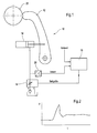
- Fig. 1 shows a schematic partial representation of a conventional winding device 10, wherein the secondary lever 12 can be acted upon by a respective hydraulic cylinder 14 which is controllable by means of a control device 16 via an actuator 18, which is designed as a proportional directional control valve. Simplified, such an actuator 18 can be represented as an electrically adjustable throttle.
- the pressure actually prevailing in the hydraulic cylinder 14 is detected by a pressure sensor 20 and fed to the control device 16.
- the pressure actual value obtained is compared by the pressure transducer 20 with an external setpoint supplied to the control device 16, whereupon the control device 16 calculates and outputs a corresponding control signal for the actuator 18 designed as a proportional directional control valve.
- the invention has for its object to provide an improved winding device of the type mentioned, in which the risk of occurrence of excessive line forces in the transition from the primary winding phase to the secondary winding phase is reduced or eliminated.
- the force or pressure limitation is thus in a separate limiting element, which may be provided between the control device and the secondary levers and brings a correspondingly shorter reaction time with it.
- the secondary levers can thus be applied virtually unrestrained to the newly wound drum without the risk of greater line force overshoot. It is no time-consuming, slow approach to the transfer point longer required. The commissioning, transfer and possible troubleshooting is significantly simplified, and in particular also time is saved.
- the force or pressure limiting element preferably comprises a pressure limiting valve.
- a pressure relief valve with respect to a flow-influencing valve such as a proportional directional valve is again that the actual pressure control or limitation takes place directly in the valve itself and accordingly short reaction times are achieved.
- the force or pressure limiting valve may in particular comprise a directly controlled pressure limiting valve, in which the sealing cone lifts off against a spring force when reaching the setting or response pressure from the seat.
- the spring preload can be generated, for example mechanically and / or electrically.
- the force or pressure limiting element is provided as an actuator for at least one hydraulic cylinder acting on the secondary lever.
- the control device may be inactive in the application phase or deliver a constant manipulated variable to the force or pressure limiting element.
- the manipulated variable is preferably selected such that the setting force or the setting pressure is just above the force or the pressure which is required for the method of the secondary lever.
- the line or contact force can then be controlled or regulated again in accordance with external setpoints, for example, by means of the control device.
- the force or pressure limiting element can be variably adjustable with respect to the setting force or the setting pressure.
- this force or pressure limiting element for example manually, electrically and / or electronically adjustable.
- the pressure relief valve is suitably used as an actuator. Then no longer with a constant setpoint, but in the classic pressure control loop with setpoint specification according to the selected line force and pressure value feedback via pressure transducer.
- control device for the process of the secondary lever respectively minimum required force or pressure in particular based on determined actual values of the force or pressure and based on determined angular changes of the secondary lever per unit time can be predetermined.
- At least one in particular electronically adjustable force or pressure limiting element is provided on both sides of the material web.
- Fig. 3 shows a schematic partial representation of an exemplary embodiment of an inventive device 26 for winding a web on a spool 28.
- the web can be in particular a paper or board web.
- Tambour 28 which is guided by a primary lever in a primary winding phase, is subsequently transferred from the primary levers to secondary levers 30 in order to be wound further in a secondary winding phase.
- the material web is guided over a carrier drum (not shown), which forms a winding nip with the drum 28 or the winding 32 to be formed thereon.
- a carrier drum (not shown), which forms a winding nip with the drum 28 or the winding 32 to be formed thereon.
- the drum 28 can be pressed against the carrier drum via a tambour holder, loading lever or the like assigned to the primary levers or via the secondary lever 30.
- the pivotable about an axis 34 mounted secondary lever 30 are actuated or pivoted via hydraulic cylinder 36.
- the secondary lever 30 or hydraulic cylinder 36 which can be activated by means of a control device 38 are at least in the phase in which they are applied to the newly wound drum 28 via at least one force or pressure limiting element switchable between the control device 38 and the secondary lever 30 or hydraulic cylinder 36 controllable, which is formed in the present case, for example by a pressure relief valve 40.
- a directly controlled pressure relief valve 40 in which the sealing cone 42 lifts against the force of at least one spring 44 from the seat 46 upon reaching the setting or set pressure.
- the spring preload can be generated mechanically and / or electrically, for example.
- the pressure relief valve 40 thus serves as an actuator for at least one of the secondary lever 30 acting hydraulic cylinder 36.
- a pressure transducer 48 the actual pressure in the hydraulic cylinder 36 is detected and passed to the control device 38.
- the higher-level control device 38 compares the pressure actual value obtained from the pressure sensor 48 with an external setpoint, that is to say from the outside, in order to calculate and output a corresponding actuating signal for the pressure limiting valve 40.
- control device 38 is preferably inactive in the application phase, that is to say that in this application phase, in particular, it can supply a constant control variable to the pressure limiting valve 40.
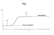
- the manipulated variable can be chosen in particular so that the setting or response pressure just above the pressure p 1 (see. Fig. 4 ), which is required for the method of the secondary lever 30.
- the limiting pressure forming setting or response pressure is in the Fig. 4 denoted by "p 2 ".
- the line or contact force can be controlled or regulated by means of the control device 38, for example in accordance with the external setpoint values.
- the pressure relief valve is suitably used as an actuator. Then no longer with a constant setpoint, but in the classic pressure control loop with setpoint specification according to the selected line force and pressure value feedback via pressure transducer.
- the minimum pressure required for moving the secondary levers 30 can be predetermined per unit of time, in particular based on determined actual pressure values and on the basis of determined angular changes of the pivotable secondary levers 38.
- a secondary lever 30, each with associated hydraulic cylinder 36 and pressure relief valve 40, may be provided on the driver's side and the drive side, respectively.
- the directly controlled pressure relief valve 40 in seat design is, as already mentioned, as an actuator for a respective associated hydraulic cylinder 36. It works as a force comparator. So that is through the Hydraulic pressure exerted force (actual value) with the spring force, that is, the force of at least one spring 44 compared. The relevant spring force results from the mechanically or electrically generated spring preload (setpoint). If the hydraulic force exceeds the spring force, the sealing cone 42 lifts off from the seat 46, as a result of which the hydraulic cylinder 36 is relieved to the tank 50.
- the higher-level control device is inactive during the entire application phase, the output manipulated variable is thus constant. It is preferably chosen so that the setting or set pressure p 2 is just above the pressure p 1 , which is required for the process of the secondary arms 30 (see. Fig. 4 ).
- the higher-level control device 38 then resumes control as before, the pressure being set to the new set value, e.g. adjusted by the operator according to the line force specification.
- the expected pressure profile was determined in test bench tests and is in the diagram according to the Fig. 4 from which it can be seen that the overshoot of the pressure and corresponding to the line force in the transition from the primary winding phase to the secondary winding phase is eliminated or at least reduced to a minimum.
- the available power here especially the oil pressure, so limited to a value, just for a move or pivoting of the secondary lever 30 is sufficient, but only so large that higher line forces are avoided.
- the advantage of a pressure limiting valve compared to a valve influencing the flow, in particular a proportional directional valve is that the actual pressure regulation or limitation takes place directly in the valve itself via a hydraulically or electrically preloaded spring provided in the pressure limiting valve, which is the classic one Control on the basis of an actual value measurement, actual value detection in the programmable logic controller (PLC), a reaction of the controller module in the programmable logic controller, an output of a setpoint to the actuator (valve) and a reaction of the valve typical relatively long reaction time is eliminated.
- PLC programmable logic controller
- the secondary levers 30 are switched to "loading", whereupon the secondary levers 30 are now controlled and take over the load from the primary levers over a time ramp.
- a secondary lever 30 may be provided on each side.
- the secondary levers 30 can now be applied virtually unrestrained to the newly wound drum 28 without the risk of greater line force overshoot. It is no time-consuming, slow approach to the transfer point longer required. The commissioning is much easier, with particular time is saved. Switching to the line force control by the secondary lever 30 is expediently only when stable conditions exist, that is, the secondary lever movement is completed. As a result, a better quality of the paper wound on the primary levers is obtained.
Landscapes
- Replacement Of Web Rolls (AREA)
- Winding Of Webs (AREA)
- Mechanically-Actuated Valves (AREA)
- Control Of Fluid Pressure (AREA)
- Servomotors (AREA)
- Vehicle Step Arrangements And Article Storage (AREA)
- Liquid Crystal (AREA)
- Burglar Alarm Systems (AREA)
Claims (13)
- Dispositif (26) pour enrouler une bande de matériau, en particulier une bande de papier ou de carton, sur un tambour (28) qui est guidé dans une phase d'enroulement primaire par des leviers primaires et qui est ensuite transféré depuis les leviers primaires à des leviers secondaires (30), afin d'être enroulé davantage dans une phase d'enroulement secondaire, la bande de matériau étant guidée sur un cylindre porteur, un espace d'enroulement étant formé entre le tambour (28) ou la bobine devant être formée sur celui-ci et le cylindre porteur, et le tambour (28) pouvant être pressé contre le cylindre porteur pour produire une force linéaire dans la fente d'enroulement par le biais d'un dispositif de retenue de tambour ou similaire associé aux leviers primaires, ou par le biais des leviers secondaires (30),
caractérisé en ce que
les leviers secondaires (30) pouvant être commandés au moyen d'un dispositif de commande (38) par le biais de cylindres hydrauliques (36) peuvent être commandés, au moins dans la phase dans laquelle ils sont appliqués contre le tambour (28) nouvellement enroulé, par le biais d'au moins un élément de limitation de pression ou de force (40) prévu entre le dispositif de commande (38) et les leviers secondaires (30). - Dispositif d'enroulement selon la revendication 1,
caractérisé en ce que
l'élément de limitation de pression ou de force comprend une soupape de limitation de pression (40). - Dispositif d'enroulement selon la revendication 2,
caractérisé en ce que
l'élément de limitation de pression ou de force comprend une soupape de limitation de pression (40) à commande directe, dans laquelle le cône d'étanchéité (42) se soulève du siège (46) à l'encontre d'une force de ressort, à l'obtention de la pression d'ajustement. - Dispositif d'enroulement selon la revendication 3,
caractérisé en ce que
la précontrainte par ressort est produite mécaniquement et/ou électriquement. - Dispositif d'enroulement selon l'une quelconque des revendications précédentes,
caractérisé en ce que
l'élément de limitation de pression ou de force (40) est prévu sous forme d'actionneur pour au moins un cylindre hydraulique (36) sollicitant les leviers secondaires (30). - Dispositif d'enroulement selon l'une quelconque des revendications précédentes,
caractérisé en ce que
le dispositif de commande (38) est inactif dans la phase d'application ou fournit une grandeur de réglage constante à l'élément de limitation de pression ou de force. - Dispositif d'enroulement selon la revendication 6,
caractérisé en ce que
la grandeur de réglage est choisie de telle sorte que la force d'ajustement ou la pression d'ajustement se situe juste au-dessus de la force ou de la pression (p1) qui est nécessaire pour le déplacement des leviers secondaires. - Dispositif d'enroulement selon l'une quelconque des revendications précédentes,
caractérisé en ce
qu'après la phase d'application au moyen du dispositif de commande (38), la force linéaire ou de pressage est commandable ou réglable. - Dispositif d'enroulement selon l'une quelconque des revendications précédentes,
caractérisé en ce que
l'élément de limitation de pression ou de force peut être ajusté de manière variable par rapport à la force d'ajustement ou la pression d'ajustement. - Dispositif d'enroulement selon la revendication 9,
caractérisé en ce que
l'élément de limitation de pression ou de force peut être ajusté manuellement. - Dispositif d'enroulement selon la revendication 9 ou 10,
caractérisé en ce que
l'élément de limitation de pression ou de force peut être ajusté électriquement et/ou électroniquement. - Dispositif d'enroulement selon l'une quelconque des revendications précédentes,
caractérisé en ce que
la force ou la pression minimale nécessaire à chaque fois pour le déplacement des leviers secondaires (30) peut être prédéfinie au moyen du dispositif de commande (38), notamment à l'aide de valeurs instantanées détectées de la force ou de la pression et à l'aide de variations angulaires détectées des leviers secondaires (30) par unité de temps. - Dispositif d'enroulement selon l'une quelconque des revendications précédentes,
caractérisé en ce
qu'au moins un élément de limitation de pression ou de force réglable notamment de manière électronique (40) est prévu à chaque fois des deux côtés de la bande de matériau.
Applications Claiming Priority (2)
| Application Number | Priority Date | Filing Date | Title |
|---|---|---|---|
| DE10327245 | 2003-06-17 | ||
| DE10327245A DE10327245A1 (de) | 2003-06-17 | 2003-06-17 | Aufwickelvorrichtung |
Publications (3)
| Publication Number | Publication Date |
|---|---|
| EP1489029A2 EP1489029A2 (fr) | 2004-12-22 |
| EP1489029A3 EP1489029A3 (fr) | 2007-04-18 |
| EP1489029B1 true EP1489029B1 (fr) | 2011-03-09 |
Family
ID=33394846
Family Applications (1)
| Application Number | Title | Priority Date | Filing Date |
|---|---|---|---|
| EP04102677A Not-in-force EP1489029B1 (fr) | 2003-06-17 | 2004-06-14 | Dispositif d'enroulement |
Country Status (3)
| Country | Link |
|---|---|
| EP (1) | EP1489029B1 (fr) |
| AT (1) | ATE501073T1 (fr) |
| DE (2) | DE10327245A1 (fr) |
Families Citing this family (2)
| Publication number | Priority date | Publication date | Assignee | Title |
|---|---|---|---|---|
| FI20080581A0 (fi) * | 2008-10-17 | 2008-10-17 | Metso Paper Inc | Laite ja menetelmä kuiturainan kiinnirullaamiseksi |
| CN103213862A (zh) * | 2013-04-26 | 2013-07-24 | 浙江晶鑫特种纸业有限公司 | 一种卷纸机 |
Family Cites Families (15)
| Publication number | Priority date | Publication date | Assignee | Title |
|---|---|---|---|---|
| US2837293A (en) * | 1955-06-27 | 1958-06-03 | Rice Barton Corp | Paper winding machine |
| US3614011A (en) * | 1969-12-22 | 1971-10-19 | Beloit Corp | Nip relieving apparatus for a reel |
| US3877654A (en) * | 1973-10-01 | 1975-04-15 | Dominion Eng Works Ltd | Reel bar loading system |
| DE3347733A1 (de) * | 1983-12-31 | 1985-11-07 | Lenze GmbH & Co KG Aerzen, 3258 Aerzen | Kontaktwalzensteuerung fuer aufwickelvorrichtung |
| FI71107C (fi) * | 1984-11-27 | 1986-11-24 | Valmet Oy | Foerfarande vid styrning av rullstolen av en pappersbana |
| DE3627463A1 (de) * | 1986-08-13 | 1988-02-18 | Smg Stahlkontor Maschinenbau G | Vorrichtung zum regeln bzw. steuern einer kontaktwalze |
| IT1229851B (it) * | 1989-05-23 | 1991-09-13 | Dolci Spa L | Dispositivo per avvolgere materiali nastriformi. |
| US5370327A (en) * | 1993-05-06 | 1994-12-06 | Beloit Technologies, Inc. | Method and apparatus for reeling a wound web roll |
| SE505333C2 (sv) * | 1995-12-20 | 1997-08-11 | Nobel Elektronik Ab | Anordning för reglering av linjekraften i en rullstolsmaskin vid papperstillverkning |
| FI106446B (fi) * | 1998-02-04 | 2001-02-15 | Valmet Corp | Menetelmä rainan rullauksessa |
| DE19819276A1 (de) * | 1998-04-30 | 1999-11-04 | Hoechst Trespaphan Gmbh | Verfahren zur Regelung der Wickeldichte von Folienrollen |
| FI110363B (fi) * | 1998-09-22 | 2002-12-31 | Metso Paper Inc | Laitteisto rainan rullaimen yhteydessä |
| US6036137A (en) * | 1998-12-17 | 2000-03-14 | Valmet-Karlstad Ab | Apparatus and method for winding paper |
| DE50111144D1 (de) * | 2001-01-22 | 2006-11-16 | Andritz Ag Maschf | Verfahren und Vorrichtung zum kontinuierlichen Aufwickeln einer Faserstoffbahn |
| DE10139340A1 (de) * | 2001-08-10 | 2003-02-27 | Voith Paper Patent Gmbh | Aufwickelvorrichtung |
-
2003
- 2003-06-17 DE DE10327245A patent/DE10327245A1/de not_active Withdrawn
-
2004
- 2004-06-14 EP EP04102677A patent/EP1489029B1/fr not_active Not-in-force
- 2004-06-14 DE DE502004012278T patent/DE502004012278D1/de active Active
- 2004-06-14 AT AT04102677T patent/ATE501073T1/de active
Also Published As
| Publication number | Publication date |
|---|---|
| DE502004012278D1 (de) | 2011-04-21 |
| DE10327245A1 (de) | 2005-01-05 |
| ATE501073T1 (de) | 2011-03-15 |
| EP1489029A2 (fr) | 2004-12-22 |
| EP1489029A3 (fr) | 2007-04-18 |
Similar Documents
| Publication | Publication Date | Title |
|---|---|---|
| DE102005014416B4 (de) | Luftservozylindervorrichtung und Steuerverfahren hierfür | |
| DE102004012294B4 (de) | Hochgeschwindigkeitsantriebsverfahren und -system für Druckzylinder | |
| EP0697317B1 (fr) | Procédé et dispositif pour le contrÔle de pression | |
| DE3530204B4 (de) | Mechanisch angetriebene Ziehpresse | |
| DE10158985A1 (de) | Dehnungssteuerung im Einzug einer Druckmaschine | |
| EP1763638B1 (fr) | Cylindre a agent sous pression avec conversion de pression | |
| DE3608182C2 (fr) | ||
| DE2108783C3 (de) | Einrichtung zum automatischen Regeln der Dicke von Flachwalzgut | |
| EP1489029B1 (fr) | Dispositif d'enroulement | |
| DE3240602C2 (fr) | ||
| DE4327313C2 (de) | Verfahren zur Druckregelung einer hydrostatischen Maschine mit verstellbarem Fördervolumen | |
| EP0211313B1 (fr) | Procédé et dispositif pour enrouler une bande | |
| DE1293711B (de) | Hydraulische Anstellvorrichtung fuer Walzwerke | |
| DE10302666B4 (de) | Verfahren und Anordnung zum Kontrollieren eines Streichspalts | |
| DE2427466A1 (de) | Doppeltwirkende bremsvorrichtung fuer eine rollenschneidmaschine oder dgl. | |
| DE2704517C3 (de) | Vorrichtung zur Steuerung sowohl der Verschiebung als auch der Kraftübertragung bei einer längs verschiebbaren Antriebsvorrichtung | |
| DE2657986A1 (de) | Richtmaschine zum richten von blechen und flachmaterialien | |
| DE102010056295A1 (de) | Verfahren zur Regelung der Bahnspannung in einem einen Tänzer aufweisenden Bahnspannungsabschnitt | |
| EP2516737B1 (fr) | Agencement pour le reglage de la position d'un cylindre ou de la pression dans l'ecartement des cylindres, d'une machine de production de bandes de matiere fibreuse | |
| DE102010022783B4 (de) | Stift zum Fangen und Positionieren von zu stanzenden und/oder zu biegendem Bandmaterial | |
| DE102018217337A1 (de) | Bewegungsvorrichtung, Reifenhandhabungsvorrichtung und Verfahren zum Betrieb eines fluidischen Aktors | |
| DE10139340A1 (de) | Aufwickelvorrichtung | |
| EP0122230A1 (fr) | Dispositif pour régler la tension dans un élement allongé | |
| DE1460632C3 (fr) | ||
| WO2012167959A1 (fr) | Dispositif à fluide |
Legal Events
| Date | Code | Title | Description |
|---|---|---|---|
| PUAI | Public reference made under article 153(3) epc to a published international application that has entered the european phase |
Free format text: ORIGINAL CODE: 0009012 |
|
| AK | Designated contracting states |
Kind code of ref document: A2 Designated state(s): AT BE BG CH CY CZ DE DK EE ES FI FR GB GR HU IE IT LI LU MC NL PL PT RO SE SI SK TR |
|
| AX | Request for extension of the european patent |
Extension state: AL HR LT LV MK |
|
| RAP1 | Party data changed (applicant data changed or rights of an application transferred) |
Owner name: VOITH PATENT GMBH |
|
| PUAL | Search report despatched |
Free format text: ORIGINAL CODE: 0009013 |
|
| AK | Designated contracting states |
Kind code of ref document: A3 Designated state(s): AT BE BG CH CY CZ DE DK EE ES FI FR GB GR HU IE IT LI LU MC NL PL PT RO SE SI SK TR |
|
| AX | Request for extension of the european patent |
Extension state: AL HR LT LV MK |
|
| 17P | Request for examination filed |
Effective date: 20071018 |
|
| AKX | Designation fees paid |
Designated state(s): AT BE BG CH CY CZ DE DK EE ES FI FR GB GR HU IE IT LI LU MC NL PL PT RO SE SI SK TR |
|
| 17Q | First examination report despatched |
Effective date: 20100319 |
|
| GRAP | Despatch of communication of intention to grant a patent |
Free format text: ORIGINAL CODE: EPIDOSNIGR1 |
|
| GRAS | Grant fee paid |
Free format text: ORIGINAL CODE: EPIDOSNIGR3 |
|
| GRAA | (expected) grant |
Free format text: ORIGINAL CODE: 0009210 |
|
| AK | Designated contracting states |
Kind code of ref document: B1 Designated state(s): AT BE BG CH CY CZ DE DK EE ES FI FR GB GR HU IE IT LI LU MC NL PL PT RO SE SI SK TR |
|
| REG | Reference to a national code |
Ref country code: GB Ref legal event code: FG4D Free format text: NOT ENGLISH |
|
| REG | Reference to a national code |
Ref country code: CH Ref legal event code: EP |
|
| REG | Reference to a national code |
Ref country code: IE Ref legal event code: FG4D Free format text: LANGUAGE OF EP DOCUMENT: GERMAN |
|
| REF | Corresponds to: |
Ref document number: 502004012278 Country of ref document: DE Date of ref document: 20110421 Kind code of ref document: P |
|
| REG | Reference to a national code |
Ref country code: DE Ref legal event code: R096 Ref document number: 502004012278 Country of ref document: DE Effective date: 20110421 |
|
| REG | Reference to a national code |
Ref country code: NL Ref legal event code: VDEP Effective date: 20110309 |
|
| PG25 | Lapsed in a contracting state [announced via postgrant information from national office to epo] |
Ref country code: ES Free format text: LAPSE BECAUSE OF FAILURE TO SUBMIT A TRANSLATION OF THE DESCRIPTION OR TO PAY THE FEE WITHIN THE PRESCRIBED TIME-LIMIT Effective date: 20110620 Ref country code: SE Free format text: LAPSE BECAUSE OF FAILURE TO SUBMIT A TRANSLATION OF THE DESCRIPTION OR TO PAY THE FEE WITHIN THE PRESCRIBED TIME-LIMIT Effective date: 20110309 Ref country code: GR Free format text: LAPSE BECAUSE OF FAILURE TO SUBMIT A TRANSLATION OF THE DESCRIPTION OR TO PAY THE FEE WITHIN THE PRESCRIBED TIME-LIMIT Effective date: 20110610 |
|
| PG25 | Lapsed in a contracting state [announced via postgrant information from national office to epo] |
Ref country code: SI Free format text: LAPSE BECAUSE OF FAILURE TO SUBMIT A TRANSLATION OF THE DESCRIPTION OR TO PAY THE FEE WITHIN THE PRESCRIBED TIME-LIMIT Effective date: 20110309 Ref country code: NL Free format text: LAPSE BECAUSE OF FAILURE TO SUBMIT A TRANSLATION OF THE DESCRIPTION OR TO PAY THE FEE WITHIN THE PRESCRIBED TIME-LIMIT Effective date: 20110309 Ref country code: BG Free format text: LAPSE BECAUSE OF FAILURE TO SUBMIT A TRANSLATION OF THE DESCRIPTION OR TO PAY THE FEE WITHIN THE PRESCRIBED TIME-LIMIT Effective date: 20110609 Ref country code: CY Free format text: LAPSE BECAUSE OF FAILURE TO SUBMIT A TRANSLATION OF THE DESCRIPTION OR TO PAY THE FEE WITHIN THE PRESCRIBED TIME-LIMIT Effective date: 20110309 |
|
| PGFP | Annual fee paid to national office [announced via postgrant information from national office to epo] |
Ref country code: AT Payment date: 20110613 Year of fee payment: 8 Ref country code: FI Payment date: 20110613 Year of fee payment: 8 |
|
| PGFP | Annual fee paid to national office [announced via postgrant information from national office to epo] |
Ref country code: DE Payment date: 20110622 Year of fee payment: 8 |
|
| REG | Reference to a national code |
Ref country code: IE Ref legal event code: FD4D |
|
| PG25 | Lapsed in a contracting state [announced via postgrant information from national office to epo] |
Ref country code: IE Free format text: LAPSE BECAUSE OF FAILURE TO SUBMIT A TRANSLATION OF THE DESCRIPTION OR TO PAY THE FEE WITHIN THE PRESCRIBED TIME-LIMIT Effective date: 20110309 Ref country code: EE Free format text: LAPSE BECAUSE OF FAILURE TO SUBMIT A TRANSLATION OF THE DESCRIPTION OR TO PAY THE FEE WITHIN THE PRESCRIBED TIME-LIMIT Effective date: 20110309 Ref country code: PT Free format text: LAPSE BECAUSE OF FAILURE TO SUBMIT A TRANSLATION OF THE DESCRIPTION OR TO PAY THE FEE WITHIN THE PRESCRIBED TIME-LIMIT Effective date: 20110711 |
|
| PG25 | Lapsed in a contracting state [announced via postgrant information from national office to epo] |
Ref country code: CZ Free format text: LAPSE BECAUSE OF FAILURE TO SUBMIT A TRANSLATION OF THE DESCRIPTION OR TO PAY THE FEE WITHIN THE PRESCRIBED TIME-LIMIT Effective date: 20110309 Ref country code: RO Free format text: LAPSE BECAUSE OF FAILURE TO SUBMIT A TRANSLATION OF THE DESCRIPTION OR TO PAY THE FEE WITHIN THE PRESCRIBED TIME-LIMIT Effective date: 20110309 Ref country code: SK Free format text: LAPSE BECAUSE OF FAILURE TO SUBMIT A TRANSLATION OF THE DESCRIPTION OR TO PAY THE FEE WITHIN THE PRESCRIBED TIME-LIMIT Effective date: 20110309 |
|
| PGFP | Annual fee paid to national office [announced via postgrant information from national office to epo] |
Ref country code: IT Payment date: 20110621 Year of fee payment: 8 |
|
| BERE | Be: lapsed |
Owner name: VOITH PATENT G.M.B.H. Effective date: 20110630 |
|
| PLBE | No opposition filed within time limit |
Free format text: ORIGINAL CODE: 0009261 |
|
| STAA | Information on the status of an ep patent application or granted ep patent |
Free format text: STATUS: NO OPPOSITION FILED WITHIN TIME LIMIT |
|
| REG | Reference to a national code |
Ref country code: CH Ref legal event code: PL |
|
| 26N | No opposition filed |
Effective date: 20111212 |
|
| GBPC | Gb: european patent ceased through non-payment of renewal fee |
Effective date: 20110614 |
|
| PG25 | Lapsed in a contracting state [announced via postgrant information from national office to epo] |
Ref country code: PL Free format text: LAPSE BECAUSE OF FAILURE TO SUBMIT A TRANSLATION OF THE DESCRIPTION OR TO PAY THE FEE WITHIN THE PRESCRIBED TIME-LIMIT Effective date: 20110309 Ref country code: DK Free format text: LAPSE BECAUSE OF FAILURE TO SUBMIT A TRANSLATION OF THE DESCRIPTION OR TO PAY THE FEE WITHIN THE PRESCRIBED TIME-LIMIT Effective date: 20110309 |
|
| REG | Reference to a national code |
Ref country code: FR Ref legal event code: ST Effective date: 20120229 |
|
| PG25 | Lapsed in a contracting state [announced via postgrant information from national office to epo] |
Ref country code: BE Free format text: LAPSE BECAUSE OF NON-PAYMENT OF DUE FEES Effective date: 20110630 |
|
| REG | Reference to a national code |
Ref country code: DE Ref legal event code: R097 Ref document number: 502004012278 Country of ref document: DE Effective date: 20111212 |
|
| PG25 | Lapsed in a contracting state [announced via postgrant information from national office to epo] |
Ref country code: FR Free format text: LAPSE BECAUSE OF NON-PAYMENT OF DUE FEES Effective date: 20110630 Ref country code: CH Free format text: LAPSE BECAUSE OF NON-PAYMENT OF DUE FEES Effective date: 20110630 Ref country code: LI Free format text: LAPSE BECAUSE OF NON-PAYMENT OF DUE FEES Effective date: 20110630 |
|
| PG25 | Lapsed in a contracting state [announced via postgrant information from national office to epo] |
Ref country code: GB Free format text: LAPSE BECAUSE OF NON-PAYMENT OF DUE FEES Effective date: 20110614 |
|
| PG25 | Lapsed in a contracting state [announced via postgrant information from national office to epo] |
Ref country code: FI Free format text: LAPSE BECAUSE OF NON-PAYMENT OF DUE FEES Effective date: 20120614 |
|
| REG | Reference to a national code |
Ref country code: AT Ref legal event code: MM01 Ref document number: 501073 Country of ref document: AT Kind code of ref document: T Effective date: 20120614 |
|
| PG25 | Lapsed in a contracting state [announced via postgrant information from national office to epo] |
Ref country code: IT Free format text: LAPSE BECAUSE OF NON-PAYMENT OF DUE FEES Effective date: 20120614 |
|
| REG | Reference to a national code |
Ref country code: DE Ref legal event code: R119 Ref document number: 502004012278 Country of ref document: DE Effective date: 20130101 |
|
| PG25 | Lapsed in a contracting state [announced via postgrant information from national office to epo] |
Ref country code: MC Free format text: LAPSE BECAUSE OF NON-PAYMENT OF DUE FEES Effective date: 20110630 Ref country code: DE Free format text: LAPSE BECAUSE OF NON-PAYMENT OF DUE FEES Effective date: 20130101 |
|
| PG25 | Lapsed in a contracting state [announced via postgrant information from national office to epo] |
Ref country code: LU Free format text: LAPSE BECAUSE OF NON-PAYMENT OF DUE FEES Effective date: 20110614 |
|
| PG25 | Lapsed in a contracting state [announced via postgrant information from national office to epo] |
Ref country code: AT Free format text: LAPSE BECAUSE OF NON-PAYMENT OF DUE FEES Effective date: 20120614 |
|
| PG25 | Lapsed in a contracting state [announced via postgrant information from national office to epo] |
Ref country code: TR Free format text: LAPSE BECAUSE OF FAILURE TO SUBMIT A TRANSLATION OF THE DESCRIPTION OR TO PAY THE FEE WITHIN THE PRESCRIBED TIME-LIMIT Effective date: 20110309 |
|
| PG25 | Lapsed in a contracting state [announced via postgrant information from national office to epo] |
Ref country code: HU Free format text: LAPSE BECAUSE OF FAILURE TO SUBMIT A TRANSLATION OF THE DESCRIPTION OR TO PAY THE FEE WITHIN THE PRESCRIBED TIME-LIMIT Effective date: 20110309 |