EP1485980B2 - Drehmomentmotor in segmentbauweise - Google Patents
Drehmomentmotor in segmentbauweise Download PDFInfo
- Publication number
- EP1485980B2 EP1485980B2 EP03709736A EP03709736A EP1485980B2 EP 1485980 B2 EP1485980 B2 EP 1485980B2 EP 03709736 A EP03709736 A EP 03709736A EP 03709736 A EP03709736 A EP 03709736A EP 1485980 B2 EP1485980 B2 EP 1485980B2
- Authority
- EP
- European Patent Office
- Prior art keywords
- stator
- segment
- torque motor
- segments
- frame
- Prior art date
- Legal status (The legal status is an assumption and is not a legal conclusion. Google has not performed a legal analysis and makes no representation as to the accuracy of the status listed.)
- Expired - Lifetime
Links
Images
Classifications
-
- H—ELECTRICITY
- H02—GENERATION; CONVERSION OR DISTRIBUTION OF ELECTRIC POWER
- H02K—DYNAMO-ELECTRIC MACHINES
- H02K1/00—Details of the magnetic circuit
- H02K1/06—Details of the magnetic circuit characterised by the shape, form or construction
- H02K1/12—Stationary parts of the magnetic circuit
-
- H—ELECTRICITY
- H02—GENERATION; CONVERSION OR DISTRIBUTION OF ELECTRIC POWER
- H02K—DYNAMO-ELECTRIC MACHINES
- H02K1/00—Details of the magnetic circuit
- H02K1/06—Details of the magnetic circuit characterised by the shape, form or construction
- H02K1/12—Stationary parts of the magnetic circuit
- H02K1/18—Means for mounting or fastening magnetic stationary parts on to, or to, the stator structures
- H02K1/185—Means for mounting or fastening magnetic stationary parts on to, or to, the stator structures to outer stators
-
- H—ELECTRICITY
- H02—GENERATION; CONVERSION OR DISTRIBUTION OF ELECTRIC POWER
- H02K—DYNAMO-ELECTRIC MACHINES
- H02K9/00—Arrangements for cooling or ventilating
- H02K9/22—Arrangements for cooling or ventilating by solid heat conducting material embedded in, or arranged in contact with, the stator or rotor, e.g. heat bridges
- H02K9/227—Heat sinks
-
- H—ELECTRICITY
- H02—GENERATION; CONVERSION OR DISTRIBUTION OF ELECTRIC POWER
- H02K—DYNAMO-ELECTRIC MACHINES
- H02K2213/00—Specific aspects, not otherwise provided for and not covered by codes H02K2201/00 - H02K2211/00
- H02K2213/12—Machines characterised by the modularity of some components
-
- H—ELECTRICITY
- H02—GENERATION; CONVERSION OR DISTRIBUTION OF ELECTRIC POWER
- H02K—DYNAMO-ELECTRIC MACHINES
- H02K26/00—Machines adapted to function as torque motors, i.e. to exert a torque when stalled
-
- H—ELECTRICITY
- H02—GENERATION; CONVERSION OR DISTRIBUTION OF ELECTRIC POWER
- H02K—DYNAMO-ELECTRIC MACHINES
- H02K5/00—Casings; Enclosures; Supports
- H02K5/04—Casings or enclosures characterised by the shape, form or construction thereof
- H02K5/20—Casings or enclosures characterised by the shape, form or construction thereof with channels or ducts for flow of cooling medium
- H02K5/203—Casings or enclosures characterised by the shape, form or construction thereof with channels or ducts for flow of cooling medium specially adapted for liquids, e.g. cooling jackets
Definitions
- the present invention relates to a torque motor having an annular rotor and an annular stator comprising a stator frame with iron cores and electrical windings disposed thereon.
- direct drives are used in various technical fields, in which the provided driving forces are supplied to the components to be moved without the interposition of gear elements.
- torque motors also known as torque motors
- a torque motor which has a fixed stator frame and an annular rotor running within the stator frame.
- the rotor consists of a rotor frame and permanent magnets attached to it which provide permanent excitation.
- the likewise ring-shaped stator has an iron core and an electrical winding arranged thereon.
- On the outside of the stator ring cooling elements are fixed, which are coupled with a water cooling. With a diameter of 2.5 m, this motor can generate torques of about 10,000 Nm. In addition to providing high forces, such a torque motor allows for precise positioning, high acceleration and high bandwidth speeds.
- a stepping motor is known in which the stator is divided into individual segments.
- the object of this known motor is to use by segmentation of the stator, the material required for the production of sheet iron packages more effectively, thereby reducing the cost of production, without significantly affecting the performance of the engine.
- the circular stator is subdivided into several segments, the iron cores of which then only comprise circle segments, which reduces the material waste arising during the production. Individual segments are then assembled into a stator, with all segments arranged in a single common housing.
- the electrical windings must be mounted in the housing for permanent operation of the motor, which is usually done by casting the windings in the housing.
- the object of the present invention is therefore to provide a torque motor which allows an exchange of individual sections of the electrical winding without assembly-related damage to the electrical winding and without disassembly of the entire stator and at the same time also changed after its original production, ie under changing conditions of use Performance requirements can be adjusted.
- a significant advantage of this torque motor according to the invention is that the individual stator segments have much smaller dimensions than the stator assembled from the segments.
- the individual segments can be readily manufactured using conventional machine tools. Likewise, the transport of the segmented motor is not difficult.
- the stator of the torque motor can be assembled directly on site by attaching the stator segments to the desired location in the stator frame.
- an advantage of the torque motor is that in case of a defect in the electrical winding, only the stator segment with the defective portion of the winding must be removed. Incidentally, the engine remains completely intact and operable. If care is taken to ensure that the stator segments remain easily accessible during the construction of appropriate systems, defective segments can be removed without having to remove the complete motor from the system. In addition, a repair of this engine can be performed very quickly by only a new stator segment to the Position of a defective segment is set.
- the torque motor according to the invention has the advantage that with identical stator segments different motors can be constructed, whose performance depends on the number of stator segments used. Different numbers of segments can be used in the stator without disturbing the functionality of the motor. To achieve full performance, the stator frame is fitted with stator segments along its entire circumference. If lower powers are sufficient, gaps can be left between individual stator segments, of course, taking into account the required number of poles for trouble-free operation of the motor.
- the torque motor is still operable if only a single stator segment is arranged, which then occupies a small section of, for example, 10 ° to 30 ° in the stator frame.
- This design can be used in particular if only low speeds and small torques are required but, on the other hand, high precision is desirable.
- the annular rotor consists of a rotor frame and permanent magnets attached thereto.
- a permanent-field excitation field is provided, so that a current supply to field windings of the rotor is not required.
- the torque motor requires by this waiver of electrical sliding contacts only a low maintenance.
- the electrical windings of a plurality of stator segments are electrically coupled by electrical connecting elements, wherein the connecting elements extend detachably between the stator segments.
- the type of electrical coupling of the individual windings depends on the selected operating mode. For example, several windings may be connected in parallel with blocks, which in turn are electrically connected in series.
- the connecting elements may e.g. be realized by plug or screw. As a result, a quick disassembly of individual stator segments is possible.
- the stator frame includes a lower and an upper stator ring, between which the stator segments are positioned. Between the lower and the upper stator ring extending vertically a plurality of frame webs on which the stator segments are mounted.
- the frame bars also define the distance between the upper and lower stator rings, so that all stator segments can be removed if necessary, for example, to perform maintenance.
- the stator segments can be built self-supporting and thus take over frame function.
- the frame webs In order to easily allow a circular orientation of the stator segments, the frame webs have angularly mutually standing side surfaces, which thus lie on different radial planes of the stator. It is also possible to use frame webs of different thicknesses, which makes it possible to vary the exact position of the stator segments. As a result, for example, the latching forces occurring during engine operation can be optimally adjusted.
- the torque motor In a preferred embodiment of the torque motor three coils are arranged on iron cores in each stator segment, which are each coupled to the associated coils of the adjacent stator segments. Thereby, the torque motor is formed as a three-phase AC synchronous motor (three-phase AC motor).
- the control methods and control devices generally known for direct drives are used for the control of the torque motor.
- each stator segment which has a flow channel for the passage of a cooling medium.
- the cooling can be done in the simplest case by a forming air flow.
- a liquid cooling medium is passed through sealed flow channels.
- the flow channels of adjacent stator segments are connected in series by releasable channel connectors to further facilitate the rapid disassembly of individual stator segments. If necessary, the channel connectors and the electrical connection elements are loosened to remove a stator segment. If engine operation is to be continued without this stator segment, bridging elements are used to enable the electrical coupling and forwarding of the cooling medium between the stator segments now adjacent via a gap.
- torque motor further have temperature sensors in each stator segment and an integrated measuring system, with which the relative and / or absolute position between the rotor and stator can be detected.
- the delivered measured values are evaluated by the engine control, whereby conventional methods can be used.
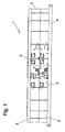
- Fig. 1 shows a side view of a torque motor according to the invention 1.
- the stator 2 is composed of a plurality of stator segments 3, of which only the middle three stator segments are drawn in more detail for simplicity.
- the stator segments 3 are lined up and arranged on the entire circumference of the stator. In a modified embodiment, for example, every second stator segment could be omitted or even fewer stator segments could be used.
- stator 4 The lower end of the stator forms a lower stator ring 4, on which the individual stator segments 3 are placed.
- the stator segments are covered on their upper side by an upper stator ring 5.
- the stator 4, 5 serve the support of the stator segments and increasing the stability of the entire stator.
- stator segments 3 are interconnected by electrical connection elements (not shown) and by releasable channel connectors 6, the function of which will be described below.
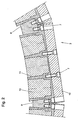
- FIG. 2 shown detail drawing shows in a sectional view from above a single stator segment 3, which is fixed in the stator.
- the attachment of the stator segment 3 by means of threaded screws 7 takes place on two lateral frame webs 8, which extend vertically between the lower stator ring 4 and the upper stator ring 5.
- the stator segments could for example also be fastened via clamping or latching connections in the stator.
- the frame webs 8 have side surfaces extending at an angle to each other, each lying on radial planes of the stator. As a result, the exact angular positioning of the stator segments is possible to produce the circular cross-section of the stator 2.
- different thickness frame webs 8 can be used to change the distance between the adjacent stator segments 3 can.
- stator segment 3 Inside the stator segment 3 are iron cores 10 and electrical windings 11. In the illustrated embodiment, three coils are formed in each stator segment by the electrical windings, so that the torque motor is driven with three current phases.
- the electrical windings 11 can be in the stator 3 in a conventional manner with synthetic resin composition, Vergusslack o.ä. potted or encapsulated.
- the housing of the stator segment 3 can be made of aluminum, for example.
- a heat sink 12 is attached to the outside of the stator 3, which serves the improved heat dissipation from the electrical windings 11.
- the heat sink 12 is again fastened, for example, with threaded screws 7 on the stator segment 3.
- recognizable channel connector 6 serve the coupling of the respective flow channels of the adjacent stator segments and must be temporarily removed when removing a stator segment.
- stator segment shown from the stator frame which may be required for example in the case of a defect of the electrical winding within this stator segment, only the threaded screws 7 need to be solved, which fasten the stator 3 to the frame webs 8. Also, the channel connectors 6 and the electrical connection elements to the adjacent stator segments must be removed. Subsequently, the stator segment can be readily removed from the motor to be replaced by a functioning stator segment.
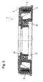
- Fig. 3 shows a side sectional view of the torque motor 1.
- the torque motor has an annular rotor 15, which may be formed in a conventional manner as a permanent-magnet internal rotor.
- the coupling between stator and rotor takes place in the illustrated example by a bearing 16, which is adapted to the specific application of the engine.
- a measuring system 17 may be provided to provide positional values.
- the lower and the upper stator ring 4, 5 may be composed of a plurality of ring segments, if this allows for larger embodiments, a lighter production.
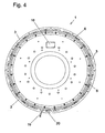
- Fig. 4 shows the assembled torque motor in a top view.
- a plurality of detachable channel connectors 6 connect the cooling systems of the respectively adjacent stator segments 3.
- a service opening 18 is provided in an engine cover.
- an electrical connection element 19 the supply of the motor current and the tap of the measurement data supplied by the measuring system 17.
- data from temperature sensors (not shown) provided in each individual stator segment can be read to monitor the operating temperature of the electrical winding.
- the guided through the heat sink 12 of the stator 3 cooling medium is passed through inlet and outlet ports 20.
- the torque motor according to the invention can be constructed in different sizes and with different power values. Due to the largely arbitrary assembly of the engine with more or less stator segments, the engine power can be easily adapted to the desired application. Torque motors that are already integrated into a system can, if necessary, be reinforced by additional stator segments if power requirements are increased, if corresponding slots for additional stator segments have already been provided in the original design. Further modifications to the structural adaptation to any applications are conceivable.
Landscapes
- Engineering & Computer Science (AREA)
- Power Engineering (AREA)
- Iron Core Of Rotating Electric Machines (AREA)
Description
- Die vorliegende Erfindung betrifft einen Drehmomentmotor mit einem ringförmigen Rotor und einem ringförmigen Stator, der einen Statorrahmen mit Eisenkernen und darauf angeordneten elektrischen Wicklungen umfasst.
- Neben herkömmlichen rotatorischen Motoren, welche Antriebsfunktionen unter Zwischenschaltung von Getriebeelementen erfüllen, werden in den verschiedensten Technikbereichen zunehmend sogenannte Direktantriebe eingesetzt, bei denen die bereitgestellten Antriebskräfte ohne Zwischenschaltung von Getriebeelementen an die zu bewegenden Bauteile geliefert werden. Zu diesen Direktantrieben werden auch sogenannte Drehmomentmotoren (auch bekannt als Torquemotoren) der oben genannten Art gerechnet.
- Aus der Firmenschrift "Direct Drives & Systems" der Firma ETEL S.A., Schweiz, Version 1.1-01/07/99, ist ein Drehmomentmotor bekannt, der einen festen Statorrahmen und einen ringförmigen innerhalb des Statorrahmens laufenden Rotor besitzt. Der Rotor besteht aus einem Rotorrahmen und darauf befestigten Permanentmagneten, die eine Permanenterregung bereitstellen. Der ebenfalls ringförmig gebildete Stator besitzt einen Eisenkern und eine darauf angeordnete elektrische Wicklung. An der Außenseite des Statorrings sind Kühlelemente befestigt, die mit einer Wasserkühlung gekoppelt sind. Dieser Motor kann bei einem Durchmesser von 2,5 m Drehmomente von etwa 10.000 Nm erzeugen. Neben der Bereitstellung großer Kräfte ermöglicht ein solcher Drehmomentmotor eine präzise Positionierung, große Beschleunigungen und Geschwindigkeiten in einer großen Bandbreite. Wie bei anderen großen Elektromotoren besteht allerdings auch hier das Problem, dass sehr große und schwere Drehteile angefertigt, transportiert und zusammengebaut werden müssen, wodurch die Herstellungskosten erheblich beeinflusst werden. Da derartige Direktantriebe häufig in teuren Gesamtanlagen eingesetzt werden, ist die Zuverlässigkeit des Motors ein weiteres wichtiges Kriterium. Eine der wichtigsten Fehlerquellen wird darin gesehen, dass die elektrische Wicklung des Motors beschädigt wird und beispielsweise ein Kurzschluss zwischen einzelnen Windungen eintritt. In einem solchen Fall muss der komplette Motor ausgebaut werden, um die elektrische Wicklung auszutauschen. Üblicherweise sind die einzelnen Windungen in einer Vergussmasse aus Kunstharz, Träufellack o.ä. eingeschlossen, so dass nur ein vollständiger Ersatz der gesamten elektrischen Wicklung möglich ist. Aufgrund der Größe dieser Direktantriebe ist die Demontage aufwändig. Da der Direktantrieb wesentlicher Bestandteil komplexer Anlagen ist, kann diese Anlage bei einem solchen Fehler während der gesamten Reparaturzeit nicht verwendet werden.
- Aus der
US 4,315,171 ist ein Schrittmotor bekannt, bei welchem der Stator in einzelne Segmente unterteilt ist. Die Aufgabe dieses bekannten Motors besteht darin, durch Segmentierung des Stators das für die Herstellung der Eisenblechpakete benötigte Material effektiver zu nutzen, um dadurch die Herstellungskosten zu senken, ohne die Leistungsfähigkeit des Motors wesentlich zu beeinträchtigen. Zur Lösung dieser Aufgabe wird der kreisförmige Stator in mehrere Segmente unterteilt, deren Eisenkerne daraufhin nur Kreissegmente umfassen, wodurch die bei der Herstellung anfallenden Materialabfälle reduziert werden. Einzelne Segmente werden dann zu einem Stator zusammengesetzt, wobei alle Segmente in einem einzigen gemeinsamen Gehäuse angeordnet sind. Die elektrischen Wicklungen müssen für eine dauerhafte Betriebsfähigkeit des Motors im Gehäuse befestigt werden, was üblicherweise durch Vergießen der Wicklungen im Gehäuse erfolgt. - Die Aufgabe der vorliegenden Erfindung besteht somit darin, einen Drehmomentmotor bereitzustellen, der einen Austausch einzelner Abschnitte der elektrischen Wicklung ohne montagebedingte Beschädigung der elektrischen Wicklung und ohne Demontage des gesamten Stators ermöglicht und der gleichzeitig auch nach seiner ursprünglichen Herstellung, also bei wechselnden Einsatzbedingungen, an veränderte Leistungserfordernisse angepasst werden kann.
- Diese Aufgabe wird durch den im beigefügten Anspruch 1 angegebenen Drehmomentmotor gelöst.
- Ein wesentlicher Vorteil dieses erfindungsgemäßen Drehmomentmotors besteht darin, dass die einzelnen Statorsegmente wesentlich kleinere Abmessungen haben, als der aus den Segmenten zusammengebaute Stator. Die einzelnen Segmente lassen sich unter Einsatz üblicher Werkzeugmaschinen ohne weiteres fertigen. Ebenso bereitet der Transport des in Segmente zerlegten Motors keine Schwierigkeiten. Der Stator des Drehmomentmotors kann direkt am Einsatzort zusammengebaut werden, indem die Statorsegmente an der gewünschten Stelle im Statorrahmen befestigt werden. Weiterhin besteht ein Vorteil des Drehmomentmotors darin, dass im Falle eines Defektes in der elektrischen Wicklung nur das Statorsegment mit dem defekten Abschnitt der Wicklung ausgebaut werden muss. Der Motor bleibt im Übrigen vollständig erhalten und betriebsfähig. Wenn bei der Konstruktion entsprechender Anlagen darauf geachtet wird, dass die Statorsegmente gut zugänglich bleiben, können defekte Segmente ausgebaut werden, ohne dass der komplette Motor aus der Anlage entfernt werden muss. Außerdem kann eine Reparatur dieses Motors sehr schnell durchgeführt werden, indem lediglich ein neues Statorsegment an die Position eines defekten Segments gesetzt wird.
- Schließlich bietet der erfindungsgemäße Drehmomentmotor den Vorteil, dass mit gleichartigen Statorsegmenten unterschiedliche Motoren aufgebaut werden können, deren Leistung abhängig von der Anzahl der eingesetzten Statorsegmente ist. Im Stator können unterschiedlich viele Segmente eingesetzt sein, ohne dass die Funktionsfähigkeit des Motors gestört ist. Um die volle Leistungsfähigkeit zu erzielen, wird der Statorrahmen entlang seines gesamten Umfangs mit Statorsegmenten bestückt. Wenn geringere Leistungen ausreichend sind, können zwischen einzelnen Statorsegmenten Lücken gelassen werden, natürlich unter Beachtung der erforderlichen Polzahl für einen störungsfreien Betrieb des Motors.
- Generell ist der Drehmomentmotor noch be-triebsfähig, wenn nur ein einziges Statorsegment ange-ordnet ist, welches dann einen kleinen Teilabschnitt von beispielsweise 10° bis 30° im Statorrahmen einnimmt. Diese Gestaltung kann insbesondere angewendet wer-den, wenn nur geringe Drehzahlen und kleine Drehmo-mente benötigt werden aber andererseits eine hohe Präzision wünschenswert ist.
- Bei einer vorteilhaften Ausführungsform des Drehmomentmotors besteht der ringförmige Rotor aus einem Rotorrahmen und daran befestigten Permanentmagneten. Dadurch wird ein Permanenterregerfeld bereitgestellt, so dass eine Stromzuführung zu Erregerwicklungen des Rotors nicht erforderlich ist. Der Drehmomentmotor benötigt durch diesen Verzicht auf elektrische Schleifkontakte nur eine geringe Wartung.
- Gemäß einer weitergebildeten Ausführungsform sind die elektrischen Wicklungen von mehreren Statorsegmenten durch elektrische Verbindungselemente elektrisch gekoppelt, wobei die Verbindungselemente lösbar zwischen den Statorsegmenten verlaufen. Die Art der elektrischen Kopplung der einzelnen Wicklungen hängt von der gewählten Betriebsart ab. Beispiels- weise können mehrere Wicklungen zu Blöcken parallel geschaltet sein, die ihrerseits elektrisch in Reihe geschaltet werden. Die Verbindungselemente können z.B. durch Steck- oder Schraubverbindungen realisiert werden. Dadurch ist eine schnelle Demontage einzelner Statorsegmente möglich.
- Der Statorrahmen umfasst einen unteren und einen oberen Statorring, zwischen denen die Statorsegmente positioniert sind. Zwischen dem unteren und dem oberen Statorring verlaufen senkrecht mehrere Rahmenstege, an denen die Statorsegmente befestigt sind. Die Rahmenstege definieren außerdem den Abstand zwischen dem unteren und dem oberen Statorring, so dass bei Bedarf auch sämtliche Statorsegmente entfernt werden können, um beispielsweise Wartungsarbeiten durchzuführen. Die Statorsegmente können selbsttragend aufgebaut werden und somit Rahmenfunktion mit übernehmen.
- Um eine kreisrunde Ausrichtung der Statorsegmente einfach zu ermöglichen, besitzen die Rahmenstege winklig zueinander stehende Seitenflächen, die somit auf unterschiedlichen Radialebenen des Stators liegen. Dabei können auch unterschiedlich dick ausgebildete Rahmenstege eingesetzt werden, wodurch es möglich wird, die exakte Position der Statorsegmente zu variieren. Dadurch können beispielsweise die im Motorbetrieb auftretenden Rastkräfte optimal eingestellt werden.
- Bei einer bevorzugten Ausführungsform des Drehmomentmotors sind in jedem Statorsegment drei Spulen auf Eisenkernen angeordnet, die jeweils mit den zugeordneten Spulen der benachbarten Statorsegmente gekoppelt sind. Dadurch wird der Drehmomentmotor als 3-Phasen-AC-Synchronmotor (Drei-Phasen-Wechselstrommotor) ausgebildet. Generell kommen für die Steuerung des Drehmomentmotors die allgemein für Direktantriebe bekannten Steuerverfahren und Regeleinrichtungen zum Einsatz.
- Um hohe Feldstärken durch die elektrischen Wicklungen zu erzeugen, ohne eine Beschädigung der einzelnen Spulendrähte bzw. der jeweiligen Isolierung hervorzurufen, ist es nützlich, wenn an jedem Statorsegment ein Kühlkörper befestigt ist, der einen Strömungskanal zur Durchleitung eines Kühlmediums besitzt. Die Kühlung kann im einfachsten Fall durch eine sich ausbildende Luftströmung erfolgen. Bei höheren Anforderungen wird ein flüssiges Kühlmedium durch abgedichtete Strömungskanäle geleitet. In diesem Fall sind die Strömungskanäle benachbarter Statorsegmente durch lösbare Kanalverbinder miteinander in Reihe geschaltet, um weiterhin den schnellen Ausbau einzelner Statorsegmente zu ermöglichen. Im Bedarfsfall werden die Kanalverbinder und die elektrischen Verbindungselemente gelöst, um ein Statorsegment zu entfernen. Wenn der Motorbetrieb ohne dieses Statorsegment fortgesetzt werden soll, werden überbrückungselemente eingesetzt, um die elektrische Kopplung und die Weiterleitung des Kühlmediums zwischen den nunmehr über eine Lücke benachbarten Statorsegmenten zu ermöglichen.
- Spezielle Ausführungsformen des Drehmomentmotors besitzen weiterhin Temperatursensoren in jedem Statorsegment und ein integriertes Messsystem, mit welchem die relative und/oder absolute Stellung zwischen Rotor und Stator erfasst werden kann. Die gelieferten Messwerte werden von der Motorsteuerung ausgewertet, wobei herkömmliche Verfahren einsetzbar sind.
- Weitere Vorteile, Einzelheiten und Weiterbildungen ergeben sich aus der nachfolgenden Beschreibung bevorzugter Ausführungsformen der Erfindung, unter Bezugnahme auf die Zeichnung. Es zeigen:
- Fig. 1
- eine vereinfachten Seitenansicht eines erfindungsgemäßen Drehmomentmotors;
- Fig. 2
- eine Detailzeichnung eines Statorsegments in einer geschnittenen Ansicht von oben;
- Fig. 3
- eine seitliche Schnittansicht des Drehmomentmotors;
- Fig. 4
- eine Draufsicht auf den zusammengebauten Drehmomentmotor.
-
Fig. 1 zeigt eine Seitenansicht eines erfindungsgemäßen Drehmomentmotors 1. Bei der dargestellten Ausführungsform handelt es sich um einen Synchronmotor mit einem außenliegenden ringförmigen Stator 2. Der Stator 2 ist aus mehreren Statorsegmenten 3 zusammengesetzt, von denen zur Vereinfachung nur die mittleren drei Statorsegmente detaillierter gezeichnet sind. Bei der dargestellten Ausführungsform sind die Statorsegmente 3 aneinandergereiht und am gesamten Umfang des Stators angeordnet. Bei einer abgewandelten Ausführungsform könnten beispielsweise jedes zweite Statorsegment weggelassen oder auch noch weniger Statorsegmente benutzt werden. - Den unteren Abschluss des Stators bildet ein unterer Statorring 4, auf welchem die einzelnen Statorsegmente 3 aufgesetzt sind. Die Statorsegmente sind an ihrer Oberseite von einem oberen Statorring 5 abgedeckt. Bei der in
Fig. 1 dargestellten Ausführungsform dienen die Statorringe 4, 5 der Halterung der Statorsegmente und der Erhöhung der Stabilität des gesamten Stators. - Die einzelnen Statorsegmente 3 sind untereinander durch elektrische Verbindungselemente (nicht gezeigt) und durch lösbare Kanalverbinder 6 verbunden, deren Funktion weiter unten beschrieben wird.
- Die in
Fig. 2 dargestellte Detailzeichnung zeigt in einer geschnittenen Ansicht von oben ein einzelnes Statorsegment 3, welches im Stator befestigt ist. Bei der dargestellten Ausführungsform erfolgt die Befestigung des Statorsegments 3 mit Hilfe von Gewindeschrauben 7 an zwei seitlichen Rahmenstegen 8, welche sich zwischen dem unteren Statorring 4 und dem oberen Statorring 5 lotrecht erstrecken. Bei abgewandelten Ausführungsformen könnten die Statorsegmente beispielsweise auch über Klemm- oder Rastverbindungen im Stator befestigt sein. - Aus der
Fig. 2 ist weiterhin erkennbar, dass die Rahmenstege 8 spitzwinklig zueinander verlaufende Seitenflächen besitzen, die jeweils auf Radialebenen des Stators liegen. Dadurch ist die exakte Winkelpositionierung der Statorsegmente möglich, um den kreisförmigen Querschnitt des Stators 2 herzustellen. Außerdem ist erkennbar, dass unterschiedlich dicke Rahmenstege 8 eingesetzt werden können, um den Abstand zwischen den benachbarten Statorsegmenten 3 verändern zu können. Durch die geeignete Auswahl der Rahmenstege mit der passenden Dicke können die Statorsegmente so innerhalb des Statorrahmens angeordnet werden, wie es für die optimale Lage der sich im Betrieb ausbildenden magnetischen Pole gewünscht ist. - Im Inneren des Statorsegments 3 befinden sich Eisenkerne 10 und elektrische Wicklungen 11. Bei der dargestellten Ausführungsform sind in jedem Statorsegment durch die elektrischen Wicklungen drei Spulen gebildet, so dass der Drehmomentmotor mit drei Stromphasen angesteuert wird. Die elektrischen Wicklungen 11 können innerhalb des Statorsegments 3 in herkömmlicher Weise mit Kunstharzmasse, Vergusslack o.ä. vergossen bzw. gekapselt sein. Das Gehäuse des Statorsegments 3 kann beispielsweise aus Aluminium gefertigt werden.
- Weiterhin ist an der Außenseite des Statorsegments 3 ein Kühlkörper 12 befestigt, der der verbesserten Wärmeabfuhr von den elektrischen Wicklungen 11 dient. Der Kühlkörper 12 ist beispielsweise wiederum mit Gewindeschrauben 7 am Statorsegment 3 befestigt. Innerhalb des Kühlkörpers 12 verläuft ein Strömungskanal, in welchem ein Kühlmedium strömt. Die in
Fig. 1 erkennbaren Kanalverbinder 6 dienen der Kopplung der jeweiligen Strömungskanäle der benachbarten Statorsegmente und müssen beim Ausbau eines Statorsegments zeitweise entfernt werden. - Um das in
Fig. 2 gezeigte Statorsegment aus dem Statorrahmen zu entfernen, was beispielsweise im Falle eines Defektes der elektrischen Wicklung innerhalb dieses Statorsegments erforderlich sein kann, müssen nur die Gewindeschrauben 7 gelöst werden, die das Statorsegment 3 an den Rahmenstegen 8 befestigen. Ebenfalls müssen die Kanalverbinder 6 und die elektrischen Verbindungselemente zu den benachbarten Statorsegmenten entfernt werden. Anschließend kann das Statorsegment ohne weiteres aus dem Motor heraus genommen werden, um durch ein funktionsfähiges Statorsegment ersetzt zu werden. -
Fig. 3 zeigt eine seitliche Schnittansicht des Drehmomentmotors 1. Im außenliegenden Stator 2 sind mehrere Statorsegmente 3 angeordnet. Weiterhin besitzt der Drehmomentmotor einen ringförmigen Rotor 15, der in herkömmlicher Weise als permanenterregter Innenläufer ausgebildet sein kann. Die Kopplung zwischen Stator und Rotor erfolgt in dem dargestellten Beispiel durch ein Lager 16, welches an den speziellen Einsatzzweck des Motors angepasst ist. Außerdem kann ein Messsystem 17 vorgesehen sein, um Positionswerte zu liefern. - Der untere und der obere Statorring 4, 5 können aus mehreren Ringsegmenten zusammengesetzt sein, wenn dies bei größeren Ausführungsformen eine leichtere Fertigung ermöglicht.
-
Fig. 4 zeigt den zusammengebauten Drehmomentmotor in einer Ansicht von oben. Mehrere lösbare Kanalverbinder 6 verbinden die Kühlsysteme der jeweils benachbarten Statorsegmente 3. Für gegebenenfalls erforderliche Wartungsarbeiten ist in einer Motorabdeckung eine Serviceöffnung 18 vorgesehen. Über ein elektrisches Anschlusselement 19 erfolgt die Zuführung des Motorstroms sowie der Abgriff der vom Messsystem 17 gelieferten Messdaten. Ebenso können an dieser Stelle Daten von Temperatursensoren (nicht gezeigt) ausgelesen werden, die in jedem einzelnen Statorsegment vorgesehen sind, um die Betriebstemperatur der elektrischen Wicklung zu überwachen. Das durch die Kühlkörper 12 der Statorsegmente 3 geführte Kühlmedium wird über Zu- und Abflussanschlüsse 20 geführt. - Der erfindungsgemäße Drehmomentmotor kann in unterschiedlichen Größen und mit verschiedenen Leistungswerten aufgebaut werden. Durch die weitgehend beliebige Bestückung des Motors mit mehr oder weniger Statorsegmenten kann die Motorleistung an den gewünschten Einsatzzweck ohne weiteres angepasst werden. Bereits in eine Anlage integrierte Drehmomentmotoren können bei gewachsenem Leistungsbedarf gegebenenfalls durch zusätzliche Statorsegmente verstärkt werden, wenn entsprechende Einbauplätze für zusätzliche Statorsegmente bereits bei der ursprünglichen Konzeption vorgesehen wurden. Weitere Abwandlungen zur konstruktiven Anpassung an beliebige Einsatzfälle sind denkbar.
-
- 1
- Drehmomentmotor
- 2
- Stator
- 3
- Statorsegment
- 4
- unterer Statorring
- 5
- oberer Statorring
- 6
- lösbare Kanalverbinder
- 7
- Gewindeschrauben
- 8
- Rahmenstege
- 10
- Eisenkern
- 11
- elektrische Wicklung
- 12
- Kühlkörper
- 15
- Rotor
- 16
- Lager
- 17
- Messsystem
- 18
- Serviceöffnung
- 19
- elektrisches Anschlusselement
- 20
- Zu- und Abflussanschluss
Claims (11)
- Drehmomentmotor (1) mit einem ringförmigen Rotor (15) und einem ringförmigen Stator (2), der einen Statorrahmen mit Eisenkernen und darauf angeordneten elektrischen Wicklungen umfasst, wobei die Eisenkerne (10) und die elektrischen Wicklungen (11) in mehreren Statorsegmenten (3) angeordnet sind, und wobei jedes dieser Statorsegmente (3) :• eigenständig betriebsfähig aufgebaut ist;• ein eigenes Gehäuse umfasst, in welchem ein segmenteigener Eisenkern (10) und eine segmenteigene elektrische Wicklung (11) angeordnet sind;• einen vorgegebenen Winkelabschnitt ≤ 180° im Statorrahmen einnimmt;• lösbar so mit diesem Statorrahmen verbunden ist, dass es unabhängig von den weiteren Statorsegmenten sowie ohne Beschädigung seiner elektrischen Wicklung (11) und des Statorrahmens ein- und ausgebaut werden kann,dadurch gekennzeichnet, dass der Statorrahmen einen unteren (4) und einen oberen Statorring (5) umfasst, zwischen denen die Statorsegmente (3) positioniert sind, und dass zwischen dem unteren (4) und dem oberen Statorring (5) mehrere Rahmenstege (8) im wesentlichen lotrecht zu den Statorringen (4, 5) verlaufen, und der Befestigung der Statorsegmente (3) dienen, wobei die Seitenflächen der Rahmenstege (8) winklig zueinander auf unterschiedlichen Radialebenen des Stators (2) liegen.
- Drehmomentmotor nach Anspruch 1, dadurch gekennzeichnet, dass eine Vielzahl von Statorsegmenten (3) angeordnet sind, die jeweils einen Winkelabschnitt ≤ 45° im Statorrahmen einnehmen.
- Drehmomentmotor nach Anspruch 1 oder 2, dadurch gekennzeichnet, dass der Rotor (15) aus einem ringförmigen Rotorrahmen und daran befestigten Permanentmagneten besteht.
- Drehmomentmotor nach einem der Ansprüche 1 bis 3, dadurch gekennzeichnet, dass die elektrischen Wicklungen (11) von mehreren Statorsegmenten (3) durch elektrische Verbindungselemente elektrisch miteinander gekoppelt sind, die lösbar zwischen den Statorsegmenten (3) verlaufen.
- Drehmomentmotor nach Anspruch 4, dadurch gekennzeichnet, dass unterschiedlich dicke Rahmenstege (8) zwischen gleichartigen Statorsegmenten (3) eingesetzt sind, wodurch der Abstand zwischen benachbarten Statorsegmenten (3) einstellbar ist.
- Drehmomentmotor nach einem der Ansprüche 1 bis 5, dadurch gekennzeichnet, dass mehrere gleichartige Statorsegmente (3) einen geschlossenen ringförmigen Stator (2) bilden.
- Drehmomentmotor nach einem der Ansprüche 1 bis 6, dadurch gekennzeichnet, dass er als 3-Phasen-AC-Synchronmotor ausgebildet ist, wobei die elektrischen Wicklungen (11) in jedem Statorsegment (3) drei Spulen bilden, die mit den zugehörigen Spulen anderer Statorsegmente (3) gekoppelt sind.
- Drehmomentmotor nach einem der Ansprüche 1 bis 7, dadurch gekennzeichnet, dass an jedem Statorsegment (3) ein Kühlkörper (12) befestigt ist, der mindestens einen Strömungskanal besitzt, welcher von einem Kühlmedium durchströmt wird.
- Drehmomentmotor nach Anspruch 8, dadurch gekennzeichnet, dass die Strömungskanäle benachbarter Statorsegmente (3) durch lösbare Kanalverbinder (6) miteinander in Reihe geschaltet sind.
- Drehmomentmotor nach einem der Ansprüche 1 bis 9, dadurch gekennzeichnet, dass in jedem Statorsegment (3) ein Temperatursensor angeordnet ist, welcher die Temperatur der elektrischen Wicklung (11) in diesem Statorsegment überwacht.
- Drehmomentmotor nach einem der Ansprüche 1 bis 10, dadurch gekennzeichnet, dass der Stator (2) als äußerer Ring den Rotor (15) umgreift, dass zwischen Stator (2) und Rotor (15) ein Lager (16) angeordnet ist und dass ein Messsystem (17) integriert ist, welches die relative Position zwischen Rotor und Stator erfasst.
Applications Claiming Priority (3)
| Application Number | Priority Date | Filing Date | Title |
|---|---|---|---|
| DE10210071A DE10210071A1 (de) | 2002-03-08 | 2002-03-08 | Drehmomentmotor in Segmentbauweise |
| DE10210071 | 2002-03-08 | ||
| PCT/EP2003/002125 WO2003077404A1 (de) | 2002-03-08 | 2003-02-28 | Drehmomentmotor in segmentbauweise |
Publications (3)
| Publication Number | Publication Date |
|---|---|
| EP1485980A1 EP1485980A1 (de) | 2004-12-15 |
| EP1485980B1 EP1485980B1 (de) | 2005-11-30 |
| EP1485980B2 true EP1485980B2 (de) | 2010-01-20 |
Family
ID=27797588
Family Applications (1)
| Application Number | Title | Priority Date | Filing Date |
|---|---|---|---|
| EP03709736A Expired - Lifetime EP1485980B2 (de) | 2002-03-08 | 2003-02-28 | Drehmomentmotor in segmentbauweise |
Country Status (7)
| Country | Link |
|---|---|
| US (1) | US7183689B2 (de) |
| EP (1) | EP1485980B2 (de) |
| CN (1) | CN100341230C (de) |
| AT (1) | ATE311686T1 (de) |
| AU (1) | AU2003214086A1 (de) |
| DE (2) | DE10210071A1 (de) |
| WO (1) | WO2003077404A1 (de) |
Families Citing this family (35)
| Publication number | Priority date | Publication date | Assignee | Title |
|---|---|---|---|---|
| DE10354592B3 (de) * | 2003-11-21 | 2005-08-11 | Abb Technology Ag | Induktionsantrieb für einen Trenn- und/oder Erdungsschalter |
| ITBZ20040047A1 (it) * | 2004-09-20 | 2004-12-20 | High Technology Invest Bv | Generatore/motore elettrico, in particolare per l'impiego in impianti eolici, impianti a fune o idraulici. |
| EP1975425B1 (de) | 2004-11-12 | 2017-09-06 | Schaeffler Technologies AG & Co. KG | Drehverbindung |
| DE102004054974B4 (de) * | 2004-11-13 | 2015-04-02 | Schaeffler Technologies AG & Co. KG | Drehverbindung |
| DE102005036239A1 (de) * | 2005-08-02 | 2007-02-08 | Schaeffler Kg | Wälzlager-Drehverbindung |
| DE102006015065A1 (de) * | 2006-03-31 | 2007-10-18 | Siemens Ag | Einbaumotor, insbesondere Einbau-Torquemotor |
| DE102006020957A1 (de) * | 2006-05-05 | 2007-11-08 | Schaeffler Kg | Flexodruckmaschine |
| DE102007012868A1 (de) | 2007-03-17 | 2008-09-18 | Schaeffler Kg | Rundstrickmaschinenantrieb |
| DE102007018689A1 (de) | 2007-04-20 | 2008-10-23 | Schaeffler Kg | Druckmaschinenantriebs- und Lagerungsvorrichtung |
| DE102007051227A1 (de) | 2007-10-26 | 2009-04-30 | Schaeffler Kg | Elektrische Direktantriebsvorrichtung |
| FR2925240B1 (fr) | 2007-12-13 | 2013-03-29 | Defontaine | Couronne d'orientation motorisee |
| CN101990702B (zh) | 2008-04-09 | 2013-06-19 | 应用材料公司 | 具有轨道的抛光系统 |
| ES2431593T3 (es) | 2008-04-10 | 2013-11-27 | Siemens Aktiengesellschaft | Disposición de estator, generador y turbina eólica |
| DE102008030200A1 (de) | 2008-06-25 | 2009-12-31 | Schaeffler Kg | Rotationsantrieb für einen bahnführenden Zylinder |
| US20100072835A1 (en) * | 2008-09-01 | 2010-03-25 | Frederick William Klatt | Stacking Method For Electric Machines |
| NO328765B1 (no) * | 2008-11-12 | 2010-05-10 | Smart Motor As | Anordning ved en elektrisk maskin samt en framgangsmåte for tilvirkning av statorseksjoner for slike maskiner |
| IT1391770B1 (it) * | 2008-11-13 | 2012-01-27 | Rolic Invest Sarl | Generatore eolico per la generazione di energia elettrica |
| NO20092984A1 (no) * | 2009-09-11 | 2011-02-14 | Blaaster Wind Tech As | Vindturbin |
| DE102009050208A1 (de) | 2009-10-22 | 2011-05-12 | Schaeffler Technologies Gmbh & Co. Kg | Absolutwert-Winkelmesssystem |
| US8912704B2 (en) | 2010-09-23 | 2014-12-16 | Northern Power Systems, Inc. | Sectionalized electromechanical machines having low torque ripple and low cogging torque characteristics |
| US9359994B2 (en) | 2010-09-23 | 2016-06-07 | Northern Power Systems, Inc. | Module-handling tool for installing/removing modules into/from an electromagnetic rotary machine having a modularized active portion |
| US8816546B2 (en) | 2010-09-23 | 2014-08-26 | Northern Power Systems, Inc. | Electromagnetic rotary machines having modular active-coil portions and modules for such machines |
| US9281731B2 (en) | 2010-09-23 | 2016-03-08 | Northem Power Systems, Inc. | Method for maintaining a machine having a rotor and a stator |
| US8789274B2 (en) | 2010-09-23 | 2014-07-29 | Northern Power Systems, Inc. | Method and system for servicing a horizontal-axis wind power unit |
| DE102010050707A1 (de) | 2010-11-06 | 2012-05-10 | Ina - Drives & Mechatronics Gmbh & Co. Ohg | Wälzlager mit einem Direktantrieb |
| JP5353874B2 (ja) * | 2010-12-28 | 2013-11-27 | 株式会社デンソー | 回転電機の固定子及びその製造方法 |
| DE102012204721A1 (de) | 2012-03-23 | 2013-09-26 | Schaeffler Technologies AG & Co. KG | Direktantrieb für eine Rotationsmaschine, insbesondere für eine Behälterbehandlungsmaschine |
| DE102013218438A1 (de) * | 2013-09-13 | 2015-03-19 | Krones Ag | Rundläufermaschine mit Direktantrieb |
| CN103997175A (zh) * | 2014-06-04 | 2014-08-20 | 北斗航天(北京)卫星传输技术服务有限公司 | 一种独立绕线的外转子电机 |
| DE102015200297A1 (de) * | 2015-01-13 | 2016-03-31 | Schaeffler Technologies AG & Co. KG | Wälzlager-Antriebsverbindung |
| DE102015209322A1 (de) | 2015-05-21 | 2016-11-24 | Schaeffler Technologies AG & Co. KG | Motor |
| US10143427B2 (en) | 2016-01-27 | 2018-12-04 | General Electric Company | Segmented direct drive motor for use in a computed tomography system |
| US11139722B2 (en) | 2018-03-02 | 2021-10-05 | Black & Decker Inc. | Motor having an external heat sink for a power tool |
| US20220045568A1 (en) * | 2019-03-08 | 2022-02-10 | Flux Systems Pty Ltd | Method and apparatus for motor cooling |
| DE102020001265A1 (de) | 2020-02-26 | 2021-08-26 | Akustikzentrum Gmbh | Direktantrieb einer Laufrolle eines Akustik-Rollenprüfstandes |
Family Cites Families (7)
| Publication number | Priority date | Publication date | Assignee | Title |
|---|---|---|---|---|
| US4315171A (en) * | 1977-05-23 | 1982-02-09 | Ernest Schaeffer | Step motors |
| US5382859A (en) * | 1992-09-01 | 1995-01-17 | Unique Mobility | Stator and method of constructing same for high power density electric motors and generators |
| US6321439B1 (en) * | 1997-01-21 | 2001-11-27 | Siemens Westinghouse Power Corporation | Method for assembly of a stator in the field |
| DK173641B1 (da) * | 1998-12-15 | 2001-05-14 | Bonus Energy As | Generator, fortrinsvis til en vindmølle |
| AT6706U1 (de) * | 1999-10-11 | 2004-02-25 | Innova Patent Gmbh | Elektromotor |
| US6492756B1 (en) * | 2000-04-05 | 2002-12-10 | Wavecrest Laboratories, Llc | Rotary electric motor having magnetically isolated stator and rotor groups |
| US6603237B1 (en) * | 2002-01-30 | 2003-08-05 | Ramon A. Caamano | High frequency electric motor or generator including magnetic cores formed from thin film soft magnetic material |
-
2002
- 2002-03-08 DE DE10210071A patent/DE10210071A1/de not_active Withdrawn
-
2003
- 2003-02-28 AU AU2003214086A patent/AU2003214086A1/en not_active Abandoned
- 2003-02-28 DE DE50301805T patent/DE50301805D1/de not_active Expired - Lifetime
- 2003-02-28 WO PCT/EP2003/002125 patent/WO2003077404A1/de not_active Ceased
- 2003-02-28 EP EP03709736A patent/EP1485980B2/de not_active Expired - Lifetime
- 2003-02-28 CN CNB038055880A patent/CN100341230C/zh not_active Expired - Fee Related
- 2003-02-28 US US10/506,931 patent/US7183689B2/en not_active Expired - Fee Related
- 2003-02-28 AT AT03709736T patent/ATE311686T1/de not_active IP Right Cessation
Also Published As
| Publication number | Publication date |
|---|---|
| US7183689B2 (en) | 2007-02-27 |
| DE50301805D1 (de) | 2006-01-05 |
| CN100341230C (zh) | 2007-10-03 |
| EP1485980B1 (de) | 2005-11-30 |
| CN1639949A (zh) | 2005-07-13 |
| US20050082938A1 (en) | 2005-04-21 |
| ATE311686T1 (de) | 2005-12-15 |
| WO2003077404A1 (de) | 2003-09-18 |
| AU2003214086A1 (en) | 2003-09-22 |
| EP1485980A1 (de) | 2004-12-15 |
| DE10210071A1 (de) | 2003-10-09 |
Similar Documents
| Publication | Publication Date | Title |
|---|---|---|
| EP1485980B2 (de) | Drehmomentmotor in segmentbauweise | |
| EP1792381B1 (de) | Generator/elektromotor, insbesondere für die verwendung an windkraftanlagen, seilzuganlagen oder hydraulischen anlagen | |
| DE602004012340T2 (de) | Turbolader mit elektrischem Hilfsantrieb | |
| DE60311407T2 (de) | Elektrisches Motorgerät und Servolenksystem | |
| EP1173917B1 (de) | Stromerzeugereinheit aus generator und hubkolbenverbrennungsmotor als antrieb | |
| EP2742578B1 (de) | Dynamoelektrische maschine mit einem selbsttragenden gehäuse | |
| EP2508749B1 (de) | Verfahren zum Montieren einer elektrischen Maschine | |
| EP0915554A2 (de) | Elektromotor | |
| EP0894358B1 (de) | Rotorwicklung für eine elektrische maschine | |
| EP3079229A1 (de) | Kühlung einer elektrischen maschine | |
| EP3214736A1 (de) | Elektrische maschine für ein kraftfahrzeug, spulenträger für eine elektrische maschine und kraftfahrzeug | |
| DE68916689T2 (de) | Elektrischer Motor. | |
| DE3313747C2 (de) | Elektrische Maschine | |
| EP3480929A1 (de) | Gekühltes gehäuse für den stator eines direktantriebs | |
| DE4115273C1 (de) | ||
| EP2019471A2 (de) | Transversalflussmaschine | |
| DE102009057446B4 (de) | Elektrische Maschine | |
| DE102005042543A1 (de) | Permanenterregte Synchronmaschine | |
| EP1045505B1 (de) | Elektrischer, gekühlter Scheibenläufermotor | |
| WO2005091468A1 (de) | Gekühlte elektrodynamische maschine mit einem spaltrohr | |
| DE102017003992A1 (de) | Magnetgestützter EC-Motor, insbesondere Synchron-EC-Motor, und Verfahren zur Drehfelderzeugung bei einem magnetgestützten EC-Motor | |
| EP2276149A2 (de) | Wicklungsschema für einen segmentierten Ständer einer dynamoelektrischen Maschine | |
| WO2011006809A2 (de) | Segmentierter ständer für eine dynamoelektrische maschine | |
| DE102009010162A1 (de) | Elektromaschine für ein Wellenarray | |
| DE602004012750T2 (de) | Motor mit modular aufgebauten statorsegmenten |
Legal Events
| Date | Code | Title | Description |
|---|---|---|---|
| PUAI | Public reference made under article 153(3) epc to a published international application that has entered the european phase |
Free format text: ORIGINAL CODE: 0009012 |
|
| 17P | Request for examination filed |
Effective date: 20041008 |
|
| AK | Designated contracting states |
Kind code of ref document: A1 Designated state(s): AT BE BG CH CY CZ DE DK EE ES FI FR GB GR HU IE IT LI LU MC NL PT SE SI SK TR |
|
| AX | Request for extension of the european patent |
Extension state: AL LT LV MK RO |
|
| 17Q | First examination report despatched |
Effective date: 20041213 |
|
| RAP1 | Party data changed (applicant data changed or rights of an application transferred) |
Owner name: INA DRIVES & MECHATRONIC GMBH & CO. OHG |
|
| GRAP | Despatch of communication of intention to grant a patent |
Free format text: ORIGINAL CODE: EPIDOSNIGR1 |
|
| GRAS | Grant fee paid |
Free format text: ORIGINAL CODE: EPIDOSNIGR3 |
|
| GRAA | (expected) grant |
Free format text: ORIGINAL CODE: 0009210 |
|
| AK | Designated contracting states |
Kind code of ref document: B1 Designated state(s): AT BE BG CH CY CZ DE DK EE ES FI FR GB GR HU IE IT LI LU MC NL PT SE SI SK TR |
|
| PG25 | Lapsed in a contracting state [announced via postgrant information from national office to epo] |
Ref country code: FI Free format text: LAPSE BECAUSE OF FAILURE TO SUBMIT A TRANSLATION OF THE DESCRIPTION OR TO PAY THE FEE WITHIN THE PRESCRIBED TIME-LIMIT Effective date: 20051130 Ref country code: IE Free format text: LAPSE BECAUSE OF FAILURE TO SUBMIT A TRANSLATION OF THE DESCRIPTION OR TO PAY THE FEE WITHIN THE PRESCRIBED TIME-LIMIT Effective date: 20051130 Ref country code: SI Free format text: LAPSE BECAUSE OF FAILURE TO SUBMIT A TRANSLATION OF THE DESCRIPTION OR TO PAY THE FEE WITHIN THE PRESCRIBED TIME-LIMIT Effective date: 20051130 Ref country code: GB Free format text: LAPSE BECAUSE OF FAILURE TO SUBMIT A TRANSLATION OF THE DESCRIPTION OR TO PAY THE FEE WITHIN THE PRESCRIBED TIME-LIMIT Effective date: 20051130 Ref country code: SK Free format text: LAPSE BECAUSE OF FAILURE TO SUBMIT A TRANSLATION OF THE DESCRIPTION OR TO PAY THE FEE WITHIN THE PRESCRIBED TIME-LIMIT Effective date: 20051130 |
|
| REG | Reference to a national code |
Ref country code: GB Ref legal event code: FG4D Free format text: NOT ENGLISH Ref country code: CH Ref legal event code: EP |
|
| REG | Reference to a national code |
Ref country code: IE Ref legal event code: FG4D Free format text: LANGUAGE OF EP DOCUMENT: GERMAN |
|
| REF | Corresponds to: |
Ref document number: 50301805 Country of ref document: DE Date of ref document: 20060105 Kind code of ref document: P |
|
| PG25 | Lapsed in a contracting state [announced via postgrant information from national office to epo] |
Ref country code: SE Free format text: LAPSE BECAUSE OF FAILURE TO SUBMIT A TRANSLATION OF THE DESCRIPTION OR TO PAY THE FEE WITHIN THE PRESCRIBED TIME-LIMIT Effective date: 20060228 Ref country code: DK Free format text: LAPSE BECAUSE OF FAILURE TO SUBMIT A TRANSLATION OF THE DESCRIPTION OR TO PAY THE FEE WITHIN THE PRESCRIBED TIME-LIMIT Effective date: 20060228 Ref country code: BG Free format text: LAPSE BECAUSE OF FAILURE TO SUBMIT A TRANSLATION OF THE DESCRIPTION OR TO PAY THE FEE WITHIN THE PRESCRIBED TIME-LIMIT Effective date: 20060228 Ref country code: AT Free format text: LAPSE BECAUSE OF NON-PAYMENT OF DUE FEES Effective date: 20060228 Ref country code: MC Free format text: LAPSE BECAUSE OF NON-PAYMENT OF DUE FEES Effective date: 20060228 Ref country code: BE Free format text: LAPSE BECAUSE OF NON-PAYMENT OF DUE FEES Effective date: 20060228 Ref country code: GR Free format text: LAPSE BECAUSE OF FAILURE TO SUBMIT A TRANSLATION OF THE DESCRIPTION OR TO PAY THE FEE WITHIN THE PRESCRIBED TIME-LIMIT Effective date: 20060228 Ref country code: LU Free format text: LAPSE BECAUSE OF NON-PAYMENT OF DUE FEES Effective date: 20060228 |
|
| PG25 | Lapsed in a contracting state [announced via postgrant information from national office to epo] |
Ref country code: ES Free format text: LAPSE BECAUSE OF FAILURE TO SUBMIT A TRANSLATION OF THE DESCRIPTION OR TO PAY THE FEE WITHIN THE PRESCRIBED TIME-LIMIT Effective date: 20060313 |
|
| PG25 | Lapsed in a contracting state [announced via postgrant information from national office to epo] |
Ref country code: PT Free format text: LAPSE BECAUSE OF FAILURE TO SUBMIT A TRANSLATION OF THE DESCRIPTION OR TO PAY THE FEE WITHIN THE PRESCRIBED TIME-LIMIT Effective date: 20060502 |
|
| PG25 | Lapsed in a contracting state [announced via postgrant information from national office to epo] |
Ref country code: HU Free format text: LAPSE BECAUSE OF FAILURE TO SUBMIT A TRANSLATION OF THE DESCRIPTION OR TO PAY THE FEE WITHIN THE PRESCRIBED TIME-LIMIT Effective date: 20060601 |
|
| GBV | Gb: ep patent (uk) treated as always having been void in accordance with gb section 77(7)/1977 [no translation filed] |
Effective date: 20051130 |
|
| REG | Reference to a national code |
Ref country code: IE Ref legal event code: FD4D |
|
| ET | Fr: translation filed | ||
| PLBI | Opposition filed |
Free format text: ORIGINAL CODE: 0009260 |
|
| 26 | Opposition filed |
Opponent name: SIEMENS AG Effective date: 20060830 Opponent name: J. WALTER CO. MASCHINEN GMBH Effective date: 20060830 |
|
| PLAX | Notice of opposition and request to file observation + time limit sent |
Free format text: ORIGINAL CODE: EPIDOSNOBS2 |
|
| NLR1 | Nl: opposition has been filed with the epo |
Opponent name: SIEMENS AG Opponent name: J. WALTER CO. MASCHINEN GMBH |
|
| PG25 | Lapsed in a contracting state [announced via postgrant information from national office to epo] |
Ref country code: LI Free format text: LAPSE BECAUSE OF NON-PAYMENT OF DUE FEES Effective date: 20070228 Ref country code: CH Free format text: LAPSE BECAUSE OF NON-PAYMENT OF DUE FEES Effective date: 20070228 |
|
| PLBB | Reply of patent proprietor to notice(s) of opposition received |
Free format text: ORIGINAL CODE: EPIDOSNOBS3 |
|
| PLBP | Opposition withdrawn |
Free format text: ORIGINAL CODE: 0009264 |
|
| REG | Reference to a national code |
Ref country code: CH Ref legal event code: PL |
|
| BERE | Be: lapsed |
Owner name: INA DRIVES & MECHATRONIC G.M.B.H. & CO. OHG Effective date: 20060228 |
|
| PLBP | Opposition withdrawn |
Free format text: ORIGINAL CODE: 0009264 |
|
| PLAB | Opposition data, opponent's data or that of the opponent's representative modified |
Free format text: ORIGINAL CODE: 0009299OPPO |
|
| PG25 | Lapsed in a contracting state [announced via postgrant information from national office to epo] |
Ref country code: EE Free format text: LAPSE BECAUSE OF FAILURE TO SUBMIT A TRANSLATION OF THE DESCRIPTION OR TO PAY THE FEE WITHIN THE PRESCRIBED TIME-LIMIT Effective date: 20051130 |
|
| PG25 | Lapsed in a contracting state [announced via postgrant information from national office to epo] |
Ref country code: TR Free format text: LAPSE BECAUSE OF FAILURE TO SUBMIT A TRANSLATION OF THE DESCRIPTION OR TO PAY THE FEE WITHIN THE PRESCRIBED TIME-LIMIT Effective date: 20051130 |
|
| PLAY | Examination report in opposition despatched + time limit |
Free format text: ORIGINAL CODE: EPIDOSNORE2 |
|
| PG25 | Lapsed in a contracting state [announced via postgrant information from national office to epo] |
Ref country code: CY Free format text: LAPSE BECAUSE OF FAILURE TO SUBMIT A TRANSLATION OF THE DESCRIPTION OR TO PAY THE FEE WITHIN THE PRESCRIBED TIME-LIMIT Effective date: 20051130 |
|
| PLBC | Reply to examination report in opposition received |
Free format text: ORIGINAL CODE: EPIDOSNORE3 |
|
| PUAH | Patent maintained in amended form |
Free format text: ORIGINAL CODE: 0009272 |
|
| STAA | Information on the status of an ep patent application or granted ep patent |
Free format text: STATUS: PATENT MAINTAINED AS AMENDED |
|
| 27A | Patent maintained in amended form |
Effective date: 20100120 |
|
| AK | Designated contracting states |
Kind code of ref document: B2 Designated state(s): AT BE BG CH CY CZ DE DK EE ES FI FR GB GR HU IE IT LI LU MC NL PT SE SI SK TR |
|
| NLR2 | Nl: decision of opposition |
Effective date: 20100120 |
|
| REG | Reference to a national code |
Ref country code: ES Ref legal event code: FD2A Effective date: 20060301 |
|
| REG | Reference to a national code |
Ref country code: NL Ref legal event code: VDEP Effective date: 20100120 |
|
| PG25 | Lapsed in a contracting state [announced via postgrant information from national office to epo] |
Ref country code: NL Free format text: LAPSE BECAUSE OF FAILURE TO SUBMIT A TRANSLATION OF THE DESCRIPTION OR TO PAY THE FEE WITHIN THE PRESCRIBED TIME-LIMIT Effective date: 20100120 |
|
| PGFP | Annual fee paid to national office [announced via postgrant information from national office to epo] |
Ref country code: NL Payment date: 20100225 Year of fee payment: 8 |
|
| PGFP | Annual fee paid to national office [announced via postgrant information from national office to epo] |
Ref country code: CZ Payment date: 20110217 Year of fee payment: 9 |
|
| PG25 | Lapsed in a contracting state [announced via postgrant information from national office to epo] |
Ref country code: CZ Free format text: LAPSE BECAUSE OF NON-PAYMENT OF DUE FEES Effective date: 20120905 |
|
| REG | Reference to a national code |
Ref country code: DE Ref legal event code: R082 Ref document number: 50301805 Country of ref document: DE |
|
| REG | Reference to a national code |
Ref country code: DE Ref legal event code: R081 Ref document number: 50301805 Country of ref document: DE Owner name: SCHAEFFLER TECHNOLOGIES GMBH & CO. KG, DE Free format text: FORMER OWNER: INA - DRIVES & MECHATRONICS GMBH & CO. OHG, 98527 SUHL, DE Effective date: 20121120 Ref country code: DE Ref legal event code: R081 Ref document number: 50301805 Country of ref document: DE Owner name: SCHAEFFLER TECHNOLOGIES AG & CO. KG, DE Free format text: FORMER OWNER: INA - DRIVES & MECHATRONICS GMBH & CO. OHG, 98527 SUHL, DE Effective date: 20121120 |
|
| REG | Reference to a national code |
Ref country code: DE Ref legal event code: R081 Ref document number: 50301805 Country of ref document: DE Owner name: SCHAEFFLER TECHNOLOGIES AG & CO. KG, DE Free format text: FORMER OWNER: SCHAEFFLER TECHNOLOGIES GMBH & CO. KG, 91074 HERZOGENAURACH, DE Effective date: 20131016 Ref country code: DE Ref legal event code: R081 Ref document number: 50301805 Country of ref document: DE Owner name: SCHAEFFLER TECHNOLOGIES GMBH & CO. KG, DE Free format text: FORMER OWNER: SCHAEFFLER TECHNOLOGIES GMBH & CO. KG, 91074 HERZOGENAURACH, DE Effective date: 20131016 |
|
| REG | Reference to a national code |
Ref country code: DE Ref legal event code: R081 Ref document number: 50301805 Country of ref document: DE Owner name: SCHAEFFLER TECHNOLOGIES GMBH & CO. KG, DE Free format text: FORMER OWNER: SCHAEFFLER TECHNOLOGIES AG & CO. KG, 91074 HERZOGENAURACH, DE Effective date: 20140218 Ref country code: DE Ref legal event code: R081 Ref document number: 50301805 Country of ref document: DE Owner name: SCHAEFFLER TECHNOLOGIES AG & CO. KG, DE Free format text: FORMER OWNER: SCHAEFFLER TECHNOLOGIES AG & CO. KG, 91074 HERZOGENAURACH, DE Effective date: 20140218 |
|
| REG | Reference to a national code |
Ref country code: FR Ref legal event code: PLFP Year of fee payment: 13 |
|
| REG | Reference to a national code |
Ref country code: DE Ref legal event code: R081 Ref document number: 50301805 Country of ref document: DE Owner name: SCHAEFFLER TECHNOLOGIES AG & CO. KG, DE Free format text: FORMER OWNER: SCHAEFFLER TECHNOLOGIES GMBH & CO. KG, 91074 HERZOGENAURACH, DE Effective date: 20150211 |
|
| PGFP | Annual fee paid to national office [announced via postgrant information from national office to epo] |
Ref country code: FR Payment date: 20150227 Year of fee payment: 13 |
|
| PGFP | Annual fee paid to national office [announced via postgrant information from national office to epo] |
Ref country code: DE Payment date: 20150429 Year of fee payment: 13 |
|
| REG | Reference to a national code |
Ref country code: FR Ref legal event code: PLFP Year of fee payment: 14 |
|
| PGFP | Annual fee paid to national office [announced via postgrant information from national office to epo] |
Ref country code: IT Payment date: 20160225 Year of fee payment: 14 |
|
| REG | Reference to a national code |
Ref country code: DE Ref legal event code: R119 Ref document number: 50301805 Country of ref document: DE |
|
| REG | Reference to a national code |
Ref country code: FR Ref legal event code: ST Effective date: 20161028 |
|
| PG25 | Lapsed in a contracting state [announced via postgrant information from national office to epo] |
Ref country code: DE Free format text: LAPSE BECAUSE OF NON-PAYMENT OF DUE FEES Effective date: 20160901 Ref country code: FR Free format text: LAPSE BECAUSE OF NON-PAYMENT OF DUE FEES Effective date: 20160229 |
|
| PG25 | Lapsed in a contracting state [announced via postgrant information from national office to epo] |
Ref country code: IT Free format text: LAPSE BECAUSE OF NON-PAYMENT OF DUE FEES Effective date: 20170228 |
|
| P01 | Opt-out of the competence of the unified patent court (upc) registered |
Effective date: 20230522 |