EP1485745B1 - High speed optical element switching mechanism - Google Patents
High speed optical element switching mechanism Download PDFInfo
- Publication number
- EP1485745B1 EP1485745B1 EP03714284A EP03714284A EP1485745B1 EP 1485745 B1 EP1485745 B1 EP 1485745B1 EP 03714284 A EP03714284 A EP 03714284A EP 03714284 A EP03714284 A EP 03714284A EP 1485745 B1 EP1485745 B1 EP 1485745B1
- Authority
- EP
- European Patent Office
- Prior art keywords
- arm
- optical element
- spring
- switching mechanism
- element switching
- Prior art date
- Legal status (The legal status is an assumption and is not a legal conclusion. Google has not performed a legal analysis and makes no representation as to the accuracy of the status listed.)
- Expired - Lifetime
Links
- 230000007246 mechanism Effects 0.000 title claims description 122
- 230000003287 optical effect Effects 0.000 title claims description 121
- 230000005291 magnetic effect Effects 0.000 claims description 6
- 230000007935 neutral effect Effects 0.000 claims description 5
- 230000033001 locomotion Effects 0.000 description 26
- XEEYBQQBJWHFJM-UHFFFAOYSA-N Iron Chemical compound [Fe] XEEYBQQBJWHFJM-UHFFFAOYSA-N 0.000 description 10
- 229910052742 iron Inorganic materials 0.000 description 5
- 238000013459 approach Methods 0.000 description 4
- 230000008901 benefit Effects 0.000 description 3
- 230000005540 biological transmission Effects 0.000 description 3
- 238000005381 potential energy Methods 0.000 description 3
- 238000013016 damping Methods 0.000 description 2
- 238000010586 diagram Methods 0.000 description 2
- 230000006835 compression Effects 0.000 description 1
- 238000007906 compression Methods 0.000 description 1
- 230000003247 decreasing effect Effects 0.000 description 1
- 230000000694 effects Effects 0.000 description 1
- 239000003302 ferromagnetic material Substances 0.000 description 1
- 230000004907 flux Effects 0.000 description 1
- 230000003116 impacting effect Effects 0.000 description 1
- 238000002955 isolation Methods 0.000 description 1
- 238000000034 method Methods 0.000 description 1
- 230000010355 oscillation Effects 0.000 description 1
- 230000008569 process Effects 0.000 description 1
- 230000007704 transition Effects 0.000 description 1
Images


Classifications
-
- G—PHYSICS
- G02—OPTICS
- G02B—OPTICAL ELEMENTS, SYSTEMS OR APPARATUS
- G02B6/00—Light guides; Structural details of arrangements comprising light guides and other optical elements, e.g. couplings
- G02B6/24—Coupling light guides
- G02B6/26—Optical coupling means
- G02B6/35—Optical coupling means having switching means
- G02B6/3564—Mechanical details of the actuation mechanism associated with the moving element or mounting mechanism details
- G02B6/3566—Mechanical details of the actuation mechanism associated with the moving element or mounting mechanism details involving bending a beam, e.g. with cantilever
-
- G—PHYSICS
- G02—OPTICS
- G02B—OPTICAL ELEMENTS, SYSTEMS OR APPARATUS
- G02B26/00—Optical devices or arrangements for the control of light using movable or deformable optical elements
- G02B26/007—Optical devices or arrangements for the control of light using movable or deformable optical elements the movable or deformable optical element controlling the colour, i.e. a spectral characteristic, of the light
-
- G—PHYSICS
- G02—OPTICS
- G02B—OPTICAL ELEMENTS, SYSTEMS OR APPARATUS
- G02B26/00—Optical devices or arrangements for the control of light using movable or deformable optical elements
- G02B26/02—Optical devices or arrangements for the control of light using movable or deformable optical elements for controlling the intensity of light
-
- G—PHYSICS
- G02—OPTICS
- G02B—OPTICAL ELEMENTS, SYSTEMS OR APPARATUS
- G02B7/00—Mountings, adjusting means, or light-tight connections, for optical elements
- G02B7/18—Mountings, adjusting means, or light-tight connections, for optical elements for prisms; for mirrors
- G02B7/182—Mountings, adjusting means, or light-tight connections, for optical elements for prisms; for mirrors for mirrors
-
- G—PHYSICS
- G02—OPTICS
- G02B—OPTICAL ELEMENTS, SYSTEMS OR APPARATUS
- G02B6/00—Light guides; Structural details of arrangements comprising light guides and other optical elements, e.g. couplings
- G02B6/24—Coupling light guides
- G02B6/26—Optical coupling means
- G02B6/35—Optical coupling means having switching means
- G02B6/351—Optical coupling means having switching means involving stationary waveguides with moving interposed optical elements
-
- G—PHYSICS
- G02—OPTICS
- G02B—OPTICAL ELEMENTS, SYSTEMS OR APPARATUS
- G02B6/00—Light guides; Structural details of arrangements comprising light guides and other optical elements, e.g. couplings
- G02B6/24—Coupling light guides
- G02B6/26—Optical coupling means
- G02B6/35—Optical coupling means having switching means
- G02B6/3564—Mechanical details of the actuation mechanism associated with the moving element or mounting mechanism details
- G02B6/358—Latching of the moving element, i.e. maintaining or holding the moving element in place once operation has been performed; includes a mechanically bistable system
Definitions
- This invention generally relates to optical elements, and more specifically relates to mechanisms for high speed switching of optical elements.
- optical elements are arranged around the perimeter of a wheel. As different elements are needed, a motor or other driver rotates the wheel, stopping when the desired element is in the optical path. This allows different optical elements to be inserted into optical path as desired.
- wheel mechanisms suffer from several significant disadvantages. For example, the amount of time and energy used to switch from one element to another can be unacceptable for many applications. This is an especially significant issue when the wheel switches from one element to another that is on the opposite side of the wheel. In some cases it can be difficult to rotate the wheel fast enough to switch it from one side of the wheel to the other. Additionally, the amount of power required to move the wheel from one end of the other can be excessive. These limitations all arise from the fact that the traditional wheel provides a sequential rather than random access to the elements at the edges of the wheel.
- JP-A-2000-305150 discloses a driving device, filter switching device and optical equipment.
- the present invention provides an optical element switching mechanism that overcomes many of the disadvantages found in the prior art. Accordingly, the invention resides in an optical element switching mechanism, the optical element switching mechanism comprising:
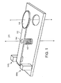
- FIG. 1 is a perspective view of an optical element switching mechanism
- FIGS. 2-4 are top schematic views of an optical element switching system
- FIG. 5 is a position diagram charting arm position for an optical element switching system
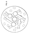
- FIG. 6 is a top schematic view of an optical element switching system.
- FIG. 7 is a cross-section top view of a latch mechanism.
- the present invention provides an optical element switching mechanism that overcomes many of the disadvantages found in the prior art.
- the switching mechanism uses a balanced arm, with an optical element attached at one end of the arm.
- the arm is suspended on an axis that allows it to rotate from a first position to a second position.
- the arm is balanced to provide low force disturbance during this movement.
- a spring is coupled to the arm that provides the rotational energy to move the arm.
- the spring is coupled such that its neutral position is between the first and second positions, and thus the spring provides the energy to move the arm from the first position to the second position and vice versa.
- a latch mechanism is also provided for selectively holding the arm in the first position or second position. Additionally, the latch mechanism can provide additional energy needed to catch and move the arm into final position.
- Switching mechanism 100 includes an arm 102, an axis 104, a spring 105 coupled to the arm, an optical element 106 and two latch mechanisms 108a and 108b.
- the arm 104 can be any structural member designed to accept the optical element.
- the arm preferably is made with sufficient rigidly to effectively control the position of optical element 106.
- the optical element 106 can be any device or combination of devices that is desirable to selectively insert into the optical path. Common devices that could be used as optical element 106 include various types and combinations of filters and mirrors and optical sources such as black body sources.
- the axis 104 can be any axis that provides for positioning and rotational movement of the arm 102.
- suitable axis 102 include flex pivots, bearings or flexural elements that provide suitable rotational movement.
- the spring 105 coupled to the arm 102 provides the rotational energy for moving the arm 102 in and out of the optical path.
- the spring 105 can be any suitable spring structure that provides sufficient energy to move the arm within desired time constraints.
- the spring is coupled such that its neutral position is substantially centered with the arm being between the optical path and the outside position. Thus, the spring 105 can provide for moving the arm 102 in both directions.
- Examples of springs that can be used for spring 105 include rotational springs such as coil, helical or torsion bars, or translational tension or compression springs.
- the latch mechanisms 108a and 108b provide the ability to selectively hold the arm in both positions.
- Each latch mechanism 108 can comprise any suitable mechanism for catching and holding the arm 102 in position. Examples of mechanisms that can be used for latch mechanism 108 include magnetic devices that provide the ability to selectively hold the arm 102. Additionally, the latch mechanism 108 can be configured to provide any additional energy needed to catch and move the arm into final position during rotation. In the alternative, a separate rotational mechanism can be added to provide the rotational energy needed to complete rotation.
- the latch mechanisms 108 hold the arm 102 in position until switching is desired.
- a latch mechanism 108 such as 108a
- the tension on the arm 102 provided by the spring 105 starts the rotational movement of the arm 102 on the axis 104 toward the opposite position.
- the opposite latch mechanism 108 (such as 108b) provides the additional energy to complete rotation to the new position, and catches and holds the arm 102 in the new position.
- the switching mechanism 100 thus provides the ability to rapidly move an optical element 106 in and out of the optical path with limited power consumption and limited physical disturbance.
- an optical switching system 200 is illustrated that utilizes multiple switching mechanisms 100 that are combined together to provide the ability to switch multiple optical elements 106 in and out of the optical path.
- three switching mechanisms 100 are configured to allow three different optical elements 106 to be selected.
- optical switching systems can be desired with any number of switching mechanisms 100 within space limitations.
- the optical switching system 200 is desired to allow one optical element 106 to swing into the optical path as another optical element 106 swings out.
- the latch mechanism 108 for the optical element 106 currently in the optical path and the latch mechanism 108 for the desired optical element 106 both release.
- the springs 105 on the switching mechanisms 100 cause the current optical element 106 to swing out of the optical path, and the desired optical element 106 to swing in.
- the optical switching system 200 is illustrated after the latch mechanism 108 for the optical element 106 currently in the optical path and the latch mechanism 108 for the desired optical element 106 have released, and the arms 102 are being rotated by springs 105 on the respective switching mechanisms 100. both release.
- the spring 105 for the old optical element 106 is providing the rotational energy to move the old optical element 106 out of the optical path.
- the spring 105 for the new optical element 106 is likewise providing the rotational energy to move the new optical element 106 into the optical path.
- the arms are being moved in opposite directions at the same time, and thus together provide cancellation of the disturbance forces that would otherwise result from the arm movement. With matched individually balanced arms, matched springs and equal deflection angles the system produces no external forces, moments or unbalanced momentum.
- the optical switching system 200 is illustrated after the latch mechanism 108 for the old optical element 106 has caught and held the arm 102 in its new position with the old optical element 106 out of the optical path. Likewise, the latch mechanism 108 for the new optical element 106 has caught and held the arm 102 in its new position with the new optical element 106 in the optical path.
- the optical system has provided the ability for one optical element to be quickly substituted for another with limited power consumption and force disturbance outside the system.
- FIG. 5 a timing diagram is illustrated that charts the position of the arm during movement from a first position to a second position, and back to the first position.
- the latch mechanism is released and the spring starts the movement of the arm.
- the parameters of the sinusoidal movement would be determined by the specific parameters of the system, such as the spring constant, rotational stiffness and the inertia of the arm, optical element, latch mechanism and any balancing weights.
- the inertia of these elements and the spring constant would be selected to have a first rotational mode mechanical resonance such that the natural period of the resulting oscillation is twice the switching speed that is required.
- the first mode of the system is designed to be at least 20Hz, with some additional settling time and margin typically provided by increasing the mode slightly above 20Hz.
- the arm passes the natural center of the spring. From this point on the spring is no longer providing additional energy to the arm and instead the spring acts to slow the arm and store potential energy for the next switch.
- the kinetic energy provided by the spring has been substantially expended. However, due to unavoidable frictions in the system, the arm has not yet been completely moved to the second position. Accordingly at time T3, the latch mechanism engages the arm to provide the additional energy needed to move the arm the rest of the way to the second position. Thus, at time T4 the arm comes to rest at the second position.
- the latch mechanism holds the arm in this position as long as desired.
- the latch mechanism releases again and the process starts again.
- the arm again passes the natural center of the spring.
- the kinetic energy provided by the spring has been substantially expended, and the latch mechanism is again engaged to provide the additional energy needed to complete the return to the first position, and at time T8 the arm comes to rest at the first position.
- the optical switching system can be implemented in many different configurations.
- the arms can be arranged so that multiple arms move in the same plane (although optical elements in the same plane must be inserted only at different times). Additional optical elements can be added beyond this point by adding additional planes on either side of the first.
- the additional planes are slightly displaced to allow clearance with the first plane and the additional planes are rotated around the beam slightly to provide non-interference for the springs.
- FIG. 6 a optical element switching system is illustrated in which a second group of three switching mechanisms 100 have been added in a different plane than the original group of three.
- an exemplary design layout could include three planes of optical elements, with three optical elements in each plane. Using this layout allows for random access to any of the nine optical elements at any time. It should be noted that while this layout could be structured to allow only one optical element in the path at a time, it could also be constructed to allow different elements from different planes to be placed in the optical path at the same time.
- the arms are preferably designed to identical deflection angles, inertia's, springs, and natural frequencies. This can be accomplished is several ways, for example, by selecting springs that are similar in stiffness and then tuning each arm to the same natural frequency. The system is operated where one filter is always inserted as a second is removed. The two resulting moments, forces, and momentum thus essentially cancel. By having each arm balanced the external forces generated by the arm movement is minimized.
- the latch mechanism are preferably designed to provide both arm holding and to provide additional kinetic energy to the arm.
- Each arm is switched (into and out of the optical path) through its own natural resonance where the limits of its harmonic motion are positions fully into the optical path and fully out of the optical path. To make switching consume as little power as possible, it is desirable for this resonance to have low damping (high Q).
- the latch mechanisms are used to hold the arm at each extreme. Without the latch mechanisms, the arm would simply oscillate through natural harmonic motion between the two extremes, where kinetic energy (motion) and potential energy (spring force) are exchanged.
- the latch mechanisms provide the extra kinetic energy needed to make up for losses in the system due to structural damping, windage and such.
- the latch mechanism can be either mechanical or magnetic, and its purpose is to hold the arm at either extreme of motion, against the force of the spring. It is desirable, but not necessary that this mechanism be able to hold the arm with no power consumption. It is also advantageous but not required that this mechanism add energy to the system to make up for losses.
- the preferred implementation of the latch mechanism is using a permanent magnet along with an electromagnetic coil so that the magnet can hold the arm and the electromagnetic coil can oppose the permanent magnet, thus releasing the arm. Since a counter-weight is typically needed to balance the optical filter the preferred implementation is placing the iron on the opposite side of the arm from the optical element.
- FIG. 7 a cross-sectional top view of a preferred latch mechanism 108 is illustrated.
- the latch mechanism 108 includes an electro-magnetic coil 706 surrounding a permanent magnet 708.
- Surrounding the magnets is a iron casing 704 that completes the flux path.
- Iron 702 is included on the end of the arm 102. In this embodiment, the iron 702 serves as to add both magnetic attraction to the arm and can act as a counter-weight to balance the arm.
- the permanent magnet 708 serves to hold the arm in place and does so without requiring the consumption of power.
- a pulse is provided to the electro-magnet 706. This causes the electro-magnet 706 to temporarily turn on and overwhelm the magnetic force of the permanent magnet 708, and thus releases the arm 102.
- the spring force causes the arm 102 to move away from before the electro-magnet 706 is turned off.
- the permanent magnet 708 on the other latch mechanism provides the additional energy needed to rotate the arm 102 into final position and hold the arm 102 until it is released by the latch mechanism.
- a second implementation of the latch mechanism is to instead locate the permanent magnet on the arm, with the electro-magnetic coil again located on the stop.
- This allows power-off holding at both extremes of motion and the use of much more sophisticated control schemes.
- the arm could be pushed at the release to add energy to the system and the capture magnet shut-off until the arm arrives and stops. Once stopped, the opposing coil is deactivated and the permanent magnet holds the arm in place.
- the advantage of this type of latching system is to minimize the disturbances and give the higher structural modes in the arm and spring enough time to settle. I.E., the push excites the arm which settles during transition and then isn't re-excited by slamming into the stop since it stops by simple harmonic motion and then is just held.
- These controls may be open loop (based only on timing) or closed loop with the addition of position sensors.
- a latch mechanism implemented as such can have the additional benefit of providing a way to restart the arm should it settle to the center, zero energy position. Specifically, by controlling the electro-magnets to be alternately energized at the natural resonance frequency of the arm, the natural harmonic motion of the arm can be built up until its amplitude is high enough to relatch the arm.
- the latch mechanism that holds the arm in position is also used to provide the additional kinetic energy needed to make up for losses, the energy could instead be provided by other rotational energy mechanisms.
- Other mechanisms include torque motors and other such devices.
- the use of a motor to provide the additional energy allows the use of alternate latch mechanisms that don't add energy to the system such as mechanical latches.
- the present invention thus provides an optical element switching mechanism that overcomes many of the disadvantages found in the prior art.
- the switching mechanism uses a balanced arm, with an optical element attached at one end of the arm.
- the arm is suspended on an axis that allows it to rotate from a first position to a second position.
- the arm is balanced to provide low force disturbance during this movement.
- a spring is coupled to the arm that provides the rotational energy to move the arm.
- the spring is coupled such that its neutral position is between the first and second positions, and thus the spring provides the energy to move the arm from the first position to the second position and vice versa.
- a latch mechanism is also provided for selectively holding the arm in the first position or second position. Additionally, the latch mechanism can provide additional energy needed to catch and move the arm into final position.
- the latch mechanism When the latch mechanism is released, the tension on the arm provided by the spring starts the rotational movement of the arm its axis toward the opposite position. As the arm approaches the opposite position, the latch mechanism provides the additional to complete rotation to the new position, and catches and holds the arm in the new position.
- the switching mechanism thus provides the ability to rapidly move an optical element in and out of the transmission path with limited power consumption and limited physical disturbance.
Landscapes
- Physics & Mathematics (AREA)
- General Physics & Mathematics (AREA)
- Optics & Photonics (AREA)
- Astronomy & Astrophysics (AREA)
- Spectroscopy & Molecular Physics (AREA)
- Mechanical Light Control Or Optical Switches (AREA)
- Lens Barrels (AREA)
- Blocking Light For Cameras (AREA)
- Structure And Mechanism Of Cameras (AREA)
Applications Claiming Priority (3)
| Application Number | Priority Date | Filing Date | Title |
|---|---|---|---|
| US10/103,534 US7013057B2 (en) | 2002-03-20 | 2002-03-20 | High speed optical element switching mechanism |
| PCT/US2003/008523 WO2003081317A1 (en) | 2002-03-20 | 2003-03-20 | High speed optical element switching mechanism |
| US103534 | 2008-04-15 |
Publications (2)
| Publication Number | Publication Date |
|---|---|
| EP1485745A1 EP1485745A1 (en) | 2004-12-15 |
| EP1485745B1 true EP1485745B1 (en) | 2006-07-26 |
Family
ID=28040418
Family Applications (1)
| Application Number | Title | Priority Date | Filing Date |
|---|---|---|---|
| EP03714284A Expired - Lifetime EP1485745B1 (en) | 2002-03-20 | 2003-03-20 | High speed optical element switching mechanism |
Country Status (6)
| Country | Link |
|---|---|
| US (1) | US7013057B2 (enExample) |
| EP (1) | EP1485745B1 (enExample) |
| JP (1) | JP2005521097A (enExample) |
| AU (1) | AU2003218290A1 (enExample) |
| DE (1) | DE60307069T2 (enExample) |
| WO (1) | WO2003081317A1 (enExample) |
Families Citing this family (9)
| Publication number | Priority date | Publication date | Assignee | Title |
|---|---|---|---|---|
| US7566099B2 (en) * | 2003-10-22 | 2009-07-28 | Lord Corporation | Furniture seatback tilt recline angle limiter and method |
| JP5021207B2 (ja) * | 2003-10-29 | 2012-09-05 | カール・ツァイス・エスエムティー・ゲーエムベーハー | フォトリソグラフィにおける光学アセンブリ |
| US7561014B2 (en) * | 2003-12-29 | 2009-07-14 | Honeywell International Inc. | Fast insertion means and method |
| US7659802B2 (en) * | 2006-03-15 | 2010-02-09 | Honeywell International Inc. | Bi-stable magnetic latch assembly |
| US7468646B2 (en) * | 2006-06-06 | 2008-12-23 | Honeywell International Inc. | Bi-stable magnetic latch assembly |
| US8193883B2 (en) * | 2007-10-30 | 2012-06-05 | Raytheon Company | Rotary switching mechanism |
| CA2711801C (en) * | 2008-01-08 | 2016-08-16 | Abb Bomem Inc. | Stiffness compensation in opto-mechanical mechanisms |
| US8853906B2 (en) | 2010-11-12 | 2014-10-07 | Raytheon Company | Optical element switching system using a Halbach array |
| JP7316059B2 (ja) * | 2019-02-22 | 2023-07-27 | 株式会社タムロン | Ndフィルタユニット、レンズ鏡筒、及び撮像装置。 |
Family Cites Families (15)
| Publication number | Priority date | Publication date | Assignee | Title |
|---|---|---|---|---|
| EP0115126A1 (en) | 1982-12-01 | 1984-08-08 | Frequency Control Products, Inc. | Switching means for single fiber optic cables |
| GB2182747B (en) | 1985-11-07 | 1989-10-04 | Gen Electric Plc | Actuator |
| JPS63228117A (ja) * | 1987-03-17 | 1988-09-22 | Olympus Optical Co Ltd | 内視鏡用光源装置 |
| JPH0546011Y2 (enExample) * | 1987-11-25 | 1993-12-01 | ||
| JP2535002Y2 (ja) * | 1991-02-08 | 1997-05-07 | ノーリツ鋼機株式会社 | スキャナにおけるレンズの位置決め装置 |
| JP2817757B2 (ja) * | 1992-08-31 | 1998-10-30 | 富士写真フイルム株式会社 | カメラの光学部材の切換装置 |
| US5455707A (en) | 1993-07-30 | 1995-10-03 | Ion Laser Technology | Apparatus and method for light beam multiplexing |
| JPH08286094A (ja) * | 1995-04-14 | 1996-11-01 | Matsushita Electric Ind Co Ltd | 中立位置復帰型電子部品 |
| US5867617A (en) * | 1997-05-19 | 1999-02-02 | E-Tek Dynamics, Inc. | High-reliability MXN fiber optic switches |
| US5852519A (en) | 1997-09-05 | 1998-12-22 | New Focus, Inc. | Positionable multi-optic holder |
| JP4438032B2 (ja) | 1999-02-19 | 2010-03-24 | キヤノン株式会社 | フィルター切り替え装置および光学機器 |
| JP2001042398A (ja) * | 1999-07-29 | 2001-02-16 | Asahi Optical Co Ltd | カメラ |
| JP2001142111A (ja) * | 1999-11-16 | 2001-05-25 | Nidec Copal Corp | 電磁アクチュエータ、シャッタ装置及び絞り装置 |
| US6266196B1 (en) | 1999-11-19 | 2001-07-24 | New Focus, Inc. | Multi-position optic mount |
| JP3839251B2 (ja) * | 2000-12-19 | 2006-11-01 | 株式会社日立グローバルストレージテクノロジーズ | 磁気ディスク装置 |
-
2002
- 2002-03-20 US US10/103,534 patent/US7013057B2/en not_active Expired - Lifetime
-
2003
- 2003-03-20 WO PCT/US2003/008523 patent/WO2003081317A1/en not_active Ceased
- 2003-03-20 DE DE60307069T patent/DE60307069T2/de not_active Expired - Lifetime
- 2003-03-20 EP EP03714284A patent/EP1485745B1/en not_active Expired - Lifetime
- 2003-03-20 JP JP2003578993A patent/JP2005521097A/ja active Pending
- 2003-03-20 AU AU2003218290A patent/AU2003218290A1/en not_active Abandoned
Also Published As
| Publication number | Publication date |
|---|---|
| AU2003218290A1 (en) | 2003-10-08 |
| EP1485745A1 (en) | 2004-12-15 |
| JP2005521097A (ja) | 2005-07-14 |
| US7013057B2 (en) | 2006-03-14 |
| DE60307069D1 (de) | 2006-09-07 |
| DE60307069T2 (de) | 2007-02-15 |
| WO2003081317A1 (en) | 2003-10-02 |
| US20030179982A1 (en) | 2003-09-25 |
Similar Documents
| Publication | Publication Date | Title |
|---|---|---|
| US6836201B1 (en) | Electrically driven bistable mechanical actuator | |
| EP1485745B1 (en) | High speed optical element switching mechanism | |
| TW201813261A (zh) | 使用多穩態狀態以用於增強影像之解析度之光學器件 | |
| US9772466B2 (en) | Optical element switching system using a Halbach array | |
| US6956453B2 (en) | Bi-stable magnetic latch | |
| CN107678119A (zh) | 一种用于光学系统三稳态多视场变倍镜头切换的装置 | |
| US7561014B2 (en) | Fast insertion means and method | |
| US4619498A (en) | Suspension and drive method and corresponding device for oscillating mirror in space telescope | |
| JPH08221915A (ja) | ディスクドライブ装置及びアクチュエータのロック方法 | |
| US5258874A (en) | Friction-free bistable device for use in space application, in particular for closing an aperture of a space application optical instrument | |
| US6950569B2 (en) | Non-linear spring force switch assembly | |
| US6806985B1 (en) | Optical system with shutter assembly having an integral shutter-mounted actuator | |
| JP5091941B2 (ja) | 双安定磁気ラッチ組立体 | |
| US6999647B2 (en) | Fast pivot mechanism | |
| JPH04286103A (ja) | 永久磁石可動型電磁石 | |
| CN115565826B (zh) | 一种基于双稳态逻辑单元的机械式逻辑门 | |
| JP2512317B2 (ja) | 電磁アクチエイタ― | |
| JP2780455B2 (ja) | アクチユエータ | |
| JP2004070162A (ja) | 磁気回路及びそれを用いた機械式光スイッチ | |
| US3217191A (en) | Oscillating timing unit electro-magnetic drive | |
| JP3492221B2 (ja) | 微小移動装置 | |
| JPS58216230A (ja) | 電磁駆動シヤツタ | |
| JPH03127015A (ja) | 副鏡揺動装置 | |
| JPH01304410A (ja) | カメラのレンズ駆動装置 |
Legal Events
| Date | Code | Title | Description |
|---|---|---|---|
| PUAI | Public reference made under article 153(3) epc to a published international application that has entered the european phase |
Free format text: ORIGINAL CODE: 0009012 |
|
| 17P | Request for examination filed |
Effective date: 20041001 |
|
| AK | Designated contracting states |
Kind code of ref document: A1 Designated state(s): AT BE BG CH CY CZ DE DK EE ES FI FR GB GR HU IE IT LI LU MC NL PT RO SE SI SK TR |
|
| AX | Request for extension of the european patent |
Extension state: AL LT LV MK |
|
| GRAP | Despatch of communication of intention to grant a patent |
Free format text: ORIGINAL CODE: EPIDOSNIGR1 |
|
| GRAS | Grant fee paid |
Free format text: ORIGINAL CODE: EPIDOSNIGR3 |
|
| GRAA | (expected) grant |
Free format text: ORIGINAL CODE: 0009210 |
|
| AK | Designated contracting states |
Kind code of ref document: B1 Designated state(s): DE FR GB IT |
|
| PG25 | Lapsed in a contracting state [announced via postgrant information from national office to epo] |
Ref country code: IT Free format text: LAPSE BECAUSE OF FAILURE TO SUBMIT A TRANSLATION OF THE DESCRIPTION OR TO PAY THE FEE WITHIN THE PRESCRIBED TIME-LIMIT;WARNING: LAPSES OF ITALIAN PATENTS WITH EFFECTIVE DATE BEFORE 2007 MAY HAVE OCCURRED AT ANY TIME BEFORE 2007. THE CORRECT EFFECTIVE DATE MAY BE DIFFERENT FROM THE ONE RECORDED. Effective date: 20060726 |
|
| REG | Reference to a national code |
Ref country code: GB Ref legal event code: FG4D |
|
| REF | Corresponds to: |
Ref document number: 60307069 Country of ref document: DE Date of ref document: 20060907 Kind code of ref document: P |
|
| ET | Fr: translation filed | ||
| PLBE | No opposition filed within time limit |
Free format text: ORIGINAL CODE: 0009261 |
|
| STAA | Information on the status of an ep patent application or granted ep patent |
Free format text: STATUS: NO OPPOSITION FILED WITHIN TIME LIMIT |
|
| 26N | No opposition filed |
Effective date: 20070427 |
|
| PGFP | Annual fee paid to national office [announced via postgrant information from national office to epo] |
Ref country code: IT Payment date: 20100324 Year of fee payment: 8 |
|
| PGFP | Annual fee paid to national office [announced via postgrant information from national office to epo] |
Ref country code: GB Payment date: 20100208 Year of fee payment: 8 |
|
| GBPC | Gb: european patent ceased through non-payment of renewal fee |
Effective date: 20110320 |
|
| PG25 | Lapsed in a contracting state [announced via postgrant information from national office to epo] |
Ref country code: IT Free format text: LAPSE BECAUSE OF NON-PAYMENT OF DUE FEES Effective date: 20110320 Ref country code: GB Free format text: LAPSE BECAUSE OF NON-PAYMENT OF DUE FEES Effective date: 20110320 |
|
| REG | Reference to a national code |
Ref country code: FR Ref legal event code: PLFP Year of fee payment: 14 |
|
| REG | Reference to a national code |
Ref country code: FR Ref legal event code: PLFP Year of fee payment: 15 |
|
| REG | Reference to a national code |
Ref country code: FR Ref legal event code: PLFP Year of fee payment: 16 |
|
| PGFP | Annual fee paid to national office [announced via postgrant information from national office to epo] |
Ref country code: DE Payment date: 20220329 Year of fee payment: 20 |
|
| PGFP | Annual fee paid to national office [announced via postgrant information from national office to epo] |
Ref country code: FR Payment date: 20220325 Year of fee payment: 20 |
|
| REG | Reference to a national code |
Ref country code: DE Ref legal event code: R071 Ref document number: 60307069 Country of ref document: DE |
|
| P01 | Opt-out of the competence of the unified patent court (upc) registered |
Effective date: 20230525 |