EP1485623B1 - Vacuum pumps with improved impeller configurations - Google Patents
Vacuum pumps with improved impeller configurations Download PDFInfo
- Publication number
- EP1485623B1 EP1485623B1 EP03711233A EP03711233A EP1485623B1 EP 1485623 B1 EP1485623 B1 EP 1485623B1 EP 03711233 A EP03711233 A EP 03711233A EP 03711233 A EP03711233 A EP 03711233A EP 1485623 B1 EP1485623 B1 EP 1485623B1
- Authority
- EP
- European Patent Office
- Prior art keywords
- pumping
- stages
- impeller
- stage
- vacuum
- Prior art date
- Legal status (The legal status is an assumption and is not a legal conclusion. Google has not performed a legal analysis and makes no representation as to the accuracy of the status listed.)
- Expired - Lifetime
Links
- 238000005086 pumping Methods 0.000 claims description 106
- 230000001172 regenerating effect Effects 0.000 claims description 30
- 230000003746 surface roughness Effects 0.000 claims description 6
- 238000012876 topography Methods 0.000 description 5
- 230000008859 change Effects 0.000 description 4
- 230000007704 transition Effects 0.000 description 3
- 230000006835 compression Effects 0.000 description 2
- 238000007906 compression Methods 0.000 description 2
- 230000007423 decrease Effects 0.000 description 2
- 238000010586 diagram Methods 0.000 description 2
- 230000002093 peripheral effect Effects 0.000 description 2
- 230000009471 action Effects 0.000 description 1
- 230000003247 decreasing effect Effects 0.000 description 1
- 230000001419 dependent effect Effects 0.000 description 1
- 238000005516 engineering process Methods 0.000 description 1
- 230000001747 exhibiting effect Effects 0.000 description 1
- 238000010438 heat treatment Methods 0.000 description 1
- 230000007246 mechanism Effects 0.000 description 1
- 238000012986 modification Methods 0.000 description 1
- 230000004048 modification Effects 0.000 description 1
- 230000009467 reduction Effects 0.000 description 1
- 238000007789 sealing Methods 0.000 description 1
- 238000001228 spectrum Methods 0.000 description 1
Images


Classifications
-
- F—MECHANICAL ENGINEERING; LIGHTING; HEATING; WEAPONS; BLASTING
- F04—POSITIVE - DISPLACEMENT MACHINES FOR LIQUIDS; PUMPS FOR LIQUIDS OR ELASTIC FLUIDS
- F04D—NON-POSITIVE-DISPLACEMENT PUMPS
- F04D17/00—Radial-flow pumps, e.g. centrifugal pumps; Helico-centrifugal pumps
- F04D17/08—Centrifugal pumps
- F04D17/16—Centrifugal pumps for displacing without appreciable compression
- F04D17/168—Pumps specially adapted to produce a vacuum
-
- F—MECHANICAL ENGINEERING; LIGHTING; HEATING; WEAPONS; BLASTING
- F04—POSITIVE - DISPLACEMENT MACHINES FOR LIQUIDS; PUMPS FOR LIQUIDS OR ELASTIC FLUIDS
- F04D—NON-POSITIVE-DISPLACEMENT PUMPS
- F04D19/00—Axial-flow pumps
- F04D19/02—Multi-stage pumps
- F04D19/04—Multi-stage pumps specially adapted to the production of a high vacuum, e.g. molecular pumps
- F04D19/046—Combinations of two or more different types of pumps
-
- F—MECHANICAL ENGINEERING; LIGHTING; HEATING; WEAPONS; BLASTING
- F04—POSITIVE - DISPLACEMENT MACHINES FOR LIQUIDS; PUMPS FOR LIQUIDS OR ELASTIC FLUIDS
- F04D—NON-POSITIVE-DISPLACEMENT PUMPS
- F04D23/00—Other rotary non-positive-displacement pumps
- F04D23/008—Regenerative pumps
Definitions
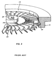
- This invention relates to turbomolecular vacuum pumps and hybrid vacuum pumps and, more particularly, to vacuum pumps having impeller configurations which assist in achieving one or more of compact pump structures, increased discharge pressure and decreased operating power in comparison with prior art vacuum pumps.
- turbomolecular vacuum pumps include a housing having an inlet port, an interior chamber containing a plurality of axial pumping stages and an exhaust port.
- the exhaust port is typically attached to a roughing vacuum pump.
- Each axial pumping stage includes a stator having inclined blades and a rotor having inclined blades. The rotor and stator blades are inclined in opposite directions. The rotor blades are rotated at high rotational speed by a motor to pump gas between the inlet port and the exhaust port.
- a typical turbomolecular vacuum pump may include nine to twelve axial pumping stages.
- Variations of the conventional turbomolecular vacuum pump often referred to as hybrid vacuum pumps have been disclosed in the prior art.
- one or more of the axial pumping stages are replaced with molecular drag stages, which form a molecular drag compressor.
- This configuration is disclosed in Varian, Inc. U.S. Patent No. 5,238,362, issued August 24, 1993 .
- Varian, Inc sells hybrid vacuum pumps including an axial turbomolecular compressor and a molecular drag compressor in a common housing.
- Molecular drag stages and regenerative stages for hybrid vacuum pumps are disclosed in Varian, Inc. U.S. Patent No. 5,358,373, issued October 25, 1994 .
- a gradual change in the design of the stators of the axial pumping stages is also disclosed in Patent No.
- Molecular drag stages include a rotating disk, or impeller, and a stator.
- the stator defines a tangential flow channel and an inlet and an outlet for the tangential flow channel.
- a stationary baffle often called a stripper, disposed in the tangential flow channel separates the inlet and the outlet.
- the momentum of the rotating disk is transferred to gas molecules within the tangential flow channel, thereby directing the molecules toward the outlet.
- Molecular drag stages were developed for molecular flow conditions.
- Another type of molecular drag stage includes a cylindrical drum that rotates within a housing having a cylindrical interior wall in close proximity to the rotating drum.
- the outer surface of the cylindrical drum or the wall is provided with a helical groove. As the drum rotates, gas is pumped through the groove by molecular drag.
- a regenerative vacuum pumping stage includes a regenerative impeller, which operates within a stator that defines a tangential flow channel.
- the regenerative impeller includes a rotating disk having spaced-apart radial ribs at or near its outer periphery. Regenerative vacuum pumping stages were developed for viscous flow conditions.
- pumping action can be produced by a fast moving flat surface dragging molecules in the direction of movement.
- very high-pressure ratios per stage can be achieved by a single disk impeller having a flat surface.
- Hybrid vacuum pumps which utilize molecular drag stages typically, have rotor-stator gaps of about eight thousandths of an inch. Reducing the gap to smaller than this dimension requires extremely tight tolerances and increases cost. This gap dimension necessitates a relatively large number of stages to achieve the desired overall compression ratio. However, these approach results in increased cost and size, and may require an unacceptably long rotor shaft.
- US 5,456,575 B discloses a non-centric pumping stage for turbo-molecular pumps.
- the number of channels in each successive pumping stage decreases from the pump inlet towards the pump outlet.
- US 5,695,316 B discloses a friction vacuum pump with pump sections of different designs.
- the cross section of a groove of a pump section can decrease or continuously change between the inlet and the outlet of the pump section.
- EP 0 256 739 A1 and EP 1 039 137 A2 disclose turbo-molecular pumps.
- the invention is defined in claim 1.
- a vacuum pump comprising a housing having an inlet port and an exhaust port, a plurality of vacuum pumping stages located within the housing and disposed between the inlet port and the exhaust port, and a motor.
- the vacuum pumping stages comprise molecular and transition flow drag stages, each including a stator and an impeller.
- the impellers of successive ones of the gas drag stages have a progressively greater surface roughness for efficient operation at progressively higher pressures.
- the motor rotates the impellers such that gas is pumped from the inlet port to the exhaust port.
- the gas drag stages may include a first stage wherein the impeller comprises a disk having a smooth pumping surface and a second stage wherein the impeller comprises a disk having a roughened pumping surface.
- the gas drag stages may further include a third stage wherein the impeller comprises a disk having a grooved pumping surface.
- the vacuum pumping stages may further comprise one or more regenerative stages.
- the impellers of successive ones of the molecular drag stages may have pumping surfaces with a surface topography for efficient operation at progressively higher pressures.
- the pumping surface of the impeller may be an annular region at or near the outer periphery of the disk.
- the pumping surface may include all or part of the front surface, all or part of the rear surface and/or all or part of the edge surface of the impeller.
- FIG. 1 A simplified cross-sectional diagram of a high vacuum pump in accordance with an embodiment of the invention is shown in Fig. 1 .
- a housing 10 defines an interior chamber 12 having an inlet port 14 and an exhaust port 16.
- the housing 10 includes a vacuum flange 18 for sealing the inlet port 14 to a vacuum chamber (not shown) to be evacuated.
- the exhaust port 16 may be connected to a roughing vacuum pump (not shown). In cases where the vacuum pump is capable of exhausting to atmospheric pressure, the roughing pump is not required.
- Each vacuum pumping stage includes a stationary member, or stator, and a rotating member, also known as an impeller or a rotor.
- the rotating member of each vacuum pumping stage is coupled by a drive shaft 50 to a motor 52.
- the shaft 50 is rotated at high speed by motor 52, causing rotation of the rotating members about a central axis and pumping of gas from inlet port 14 to exhaust port 16.
- the embodiment of Fig. 1 has nine stages. It will be understood that a different number of stages can be utilized, depending on the vacuum pumping requirements.
- the vacuum pumping stages 30, 32, ..., 46 are configured for efficient operation within a specified pressure range.
- the pressure at inlet port 14 during operation may be on the order of 10 -5 to 10 -6 torr, whereas the pressure at exhaust port 16 may be at or near atmospheric pressure.
- the pressure through the vacuum pump gradually increases from inlet port 14 to exhaust port 16.
- the characteristics of each vacuum pumping stage may be selected for efficient operation over an expected operating pressure range of that stage.
- vacuum pumping stages 30, 32 and 34 may be axial flow stages, as shown in Fig. 2 and described below.
- Vacuum pumping stages 36, 38, 40 and 42 may be molecular drag stages, as described below in connection with Figs. 3-5 and 9A-12B .
- Molecular drag stages 36, 38, 40 and 42 may have impellers, which are configured for operation at successively higher pressures, as described below.
- Vacuum pumping stages 44 and 46 may be regenerative vacuum pumping stages, as described below in connection with Figs. 6-8 , 13A and 13B .
- FIG. 2 An embodiment of an axial flow stage is shown in Fig. 2 .
- Pump housing 10 has inlet port 12.
- the axial flow stage includes a rotor 104 and a stator 110.
- the rotor 104 is connected to shaft 50 for high speed rotation about the central axis.
- the stator 110 is mounted in a fixed position relative to housing 10.
- the rotor 104 and the stator 110 each have multiple inclined blades.
- the blades of rotor 104 are inclined in an opposite direction from the blades of stator 110.
- Variations of conventional axial flow stages are disclosed in the aforementioned Patent No. 5,358,373 , which is hereby incorporated by reference.
- the rotor or impeller
- the rotor comprises a disk and the stator is provided with channels in closely spaced opposed relationship to the disk.
- gas is caused to flow through the stator channels by molecular drag produced by the rotating disk.
- the impeller may have different configurations for efficient operation at different pressures.
- a molecular drag stage includes a disk 200, an upper stator portion 202 and a lower stator portion 204 mounted within housing 10.
- the upper stator portion 202 is located in proximity to an upper surface of disk 200
- lower stator portion 204 is located in proximity to a lower surface of disk 200.
- the upper and lower stator portions 202 and 204 together constitute the stator of the molecular drag stage.
- the disk 200 is attached to shaft 50 for high speed rotation about the central axis of the vacuum pump.
- the upper stator portion 202 is provided with an upper channel 210.
- the channel 210 is located in opposed relationship to the upper surface of disk 200.
- the lower stator portion 204 is provided with a lower channel 212, which is located in opposed relationship to the lower surface of disk 200.
- the channels 210 and 212 are circular and are concentric with disk 200.
- the upper stator portion 202 includes a blockage 214 of channel 210 at one circumferential location.
- the channel 210 receives gas from the previous stage through a conduit 216 on one side of blockage 214. The gas is pumped through channel 210 by molecular drag produced by rotating disk 200.
- a conduit 220 formed in stator portions 202 and 204 interconnects channels 210 and 212 around the outer peripheral edge of disk 200.
- the lower stator portion 204 includes a blockage 222 of lower channel 212 at one circumferential location.
- the lower channel 212 receives gas on one side of blockage 222 through conduit 220 from the upper surface of disk 200 and discharges gas through a conduit 224 on the other side of blockage 222 to the next stage.
- disk 200 is rotated at high speed about shaft 50.
- Gas is received from the previous stage through conduit 216.
- the previous stage can be a molecular drag stage, an axial flow stage, or any other suitable vacuum pumping stage.
- the gas is pumped around the circumference of upper channel 210 by molecular drag produced by rotation of disk 200.
- the gas then passes through conduit 220 around the outer periphery of disk 200 to lower channel 212.
- the gas is then pumped around the circumference of lower channel 212 by molecular drag and is exhausted through conduit 224 to the next stage or to the exhaust port of the pump.
- upper channel 210 and lower channel 212 are connected such that gas flows through them in series.
- the upper and lower channels may be connected in parallel. Two or more concentric pumping channels can be used, connected in series. Additional embodiments of molecular drag stages are disclosed in the aforementioned Patent No. 5,358,373 .
- the regenerative vacuum pumping stage includes a regenerative impeller 300 which operates with a stator having an upper stator portion 302 adjacent to an upper surface of regenerative impeller 300, and a lower stator portion 304 adjacent to the lower surface of regenerative impeller 300.
- the upper stator portion 302 is omitted from Fig. 6 for clarity.
- the regenerative impeller 300 comprises a disk 305 having spaced-apart radial ribs 308 on its upper surface and spaced-apart radial ribs 310 on its lower surface.
- the ribs 308 and 310 are preferably located at or near the outer periphery of disk 305.
- Cavities 312 are defined between each pair of ribs 308, and cavities 314 are defined between each pair of ribs 310.
- the cavities 312 and 314 have curved contours formed by removing material of the disk 305 between ribs 308 and between ribs 310.
- the cross-sectional shape of the cavities 312 and 314 can be rectangular, triangular, or any other suitable shape.
- the disk 305 is attached to shaft 50 for high speed rotation around the central axis of the vacuum pump.
- the upper stator portion 302 has a circular upper channel 320 formed in opposed relationship to ribs 308 and cavities 312.
- the lower stator portion 304 has a circular lower channel 322 formed in opposed relationship to ribs 310 and cavities 314.
- the upper stator portion 302 further includes a blockage (not shown) of channel 320 at one circumferential location.
- the lower stator portion 304 includes a blockage 326 of channel 322 at one circumferential location.
- the stator portions 302 and 304 define a conduit 330 adjacent to blockage 326 that interconnects upper channel 320 and lower channel 322 around the edge of disk 305.
- Upper channel 320 receives gas from a previous stage through a conduit (not shown).
- the lower channel 322 discharges gas to a next stage through a conduit 334.
- disk 305 is rotated at high speed about shaft 50.
- Gas entering upper channel 320 from the previous stage is pumped through upper channel 320.
- the rotation of disk 305 and ribs 308 causes the gas to be pumped along a roughly helical path through cavities 312 and upper channel 320.
- the gas then passes through conduit 330 into lower channel 322 and is pumped through channel 322 by the rotation of disk 305 and ribs 310.
- the ribs 310 cause the gas to be pumped in a roughly helical path through cavities 314 and lower channel 322.
- the gas is then discharged to the next stage through conduit 334.
- the molecular drag stages in the vacuum pump of Fig. 1 may have different impeller configurations, which are optimized for operation at different pressure levels.
- Each impeller is generally disk-shaped and has at least one pumping surface at or near its outer periphery.
- the pumping surface is an annular region on the front surface, the rear surface, or both, of the disk-shaped impeller.
- the pumping surface may include the outer edge that joins the front and rear surfaces.
- Impeller 400 rotates at high speed about an axis 402 during operation.
- a stator having a pumping channel 404 is positioned in close proximity to impeller 400.
- Pumping channel 404 is typically located at or near an outer periphery of impeller 400.
- a portion of impeller 400 facing pumping channel 404 functions as a vacuum pumping surface 410.
- vacuum pumping surface 410 is the portion of impeller 400 that is exposed to pumping channel 404.
- the vacuum pumping surface 410 is typically an annular area of impeller 400 at or near its outer periphery.
- Vacuum pumping surface 410 may be located on a front surface 400a, a rear surface 400b, or both, of impeller 400. In addition, vacuum pumping surface 410 may be located on an edge surface 400c of disk-shaped impeller 400.
- the impeller 400 may include two or more concentric vacuum pumping surfaces on front surface 400a, rear surface 400b, or both, depending on the stator configuration.
- the impellers in gas drag stages of the vacuum pump are configured for efficient operation at different pressure levels in order to enhance vacuum pump operation as the pressure increases from the inlet port 14 to the exhaust port 16 of the vacuum pump.
- the vacuum pumping surface 410 of impeller 400 is configured for efficient operation over an expected pressure range of that stage in the vacuum pump.
- the vacuum pumping surfaces of the impellers in the vacuum pump have a surface topography that is selected for efficient vacuum pumping at the expected pressure range of that vacuum pumping stage.
- the vacuum pumping surface is relatively smooth for operation at relatively low pressures and has increased surface roughness for operation at higher pressures.
- the vacuum pump utilizes a series of vacuum pumping stages in which the impellers have progressively greater surface roughness for operation at progressively higher pressures.
- a set of impellers in accordance with an embodiment of the invention is shown in Figs. 9A-13B .
- the impellers may be used in different stages of the vacuum pump of Fig. 1 or in any other multiple stage vacuum pump.
- the vacuum pumping characteristics of the impellers may be varied individually or as a set within the scope of the invention.
- the set may include more or fewer impellers.
- impeller 400 may be utilized in vacuum pumping stage 36 of vacuum pump 10.
- the vacuum pumping surface 410 of impeller 400 is relatively flat and smooth, and is designed for operation at relatively low pressures.
- the flat impeller operates most efficiently at pressures in the molecular flow and the initial transition flow ranges, i.e., pressures lower than about 1 torr in mid-sized pumps.
- an impeller 500 may be utilized in vacuum pumping stage 38 of vacuum pump 10.
- Impeller 500 is configured for operation at higher pressures than impeller 400 of Figs. 9A and 9B and has a roughened vacuum pumping surface 510.
- the surface roughness depends on the expected operating pressure range and should be sufficient to increase the boundary layer adjacent to the impeller surface, i.e., to induce a thicker section of flow into the drag mechanism.
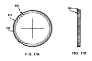
- an impeller 600 may be utilized in vacuum pumping stage 40 of vacuum pump 10.
- Vacuum pumping surfaces 610 of impeller 600 are configured for operation at higher pressures than impeller 500 of Figs. 10A and 10B and may have a series of radial grooves in vacuum pumping surfaces 610.
- the spacing and depth of the grooves depend on the expected operating pressure range.
- the grooves 612 may have depths in a range of about 1 to 2 millimeters in mid-sized pumps.
- the vacuum pumping surfaces 610 may have increased surface roughness in comparison with impeller 500 or may have any surface topography that produces efficient operation in the expected pressure range.
- an impeller 700 may be utilized in vacuum pumping stage 42 of vacuum pump 10.
- Impeller 700 has a vacuum pumping surface 710 that is configured for operation at higher pressures than impeller 600 of Figs.11A and 11B .
- Vacuum pumping surface 710 of impeller 700 may have grooves 712 that are deeper and/or more closely spaced than the grooves 612 on impeller 600.
- vacuum pumping surface 710 may have another surface topography that is selected for efficient operation in the expected operating pressure range.
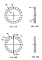
- a regenerative impeller 900 may be utilized in vacuum pumping stages 44 and 46 of vacuum pump 10.
- Impeller 900 includes a vacuum pumping surface 910 having a series of spaced-apart radial ribs 912 which define cavities 914.
- the size and shape of the ribs 912 and the corresponding cavities 914 are selected for efficient vacuum pumping over the expected operating pressure range.
- the radial extent of ribs 912 may be varied.
- the regenerative impellers in vacuum pumping stages 44 and 46 may be configured for efficient operation over different pressure ranges.
- vacuum pump 10 may include a single regenerative vacuum pumping stage or more than two regenerative vacuum pumping stages having impellers, which are configured for operation at progressively higher pressures.
- the configurations of the ribs and the cavities may be selected for efficient operation in the expected operating pressure range.
- two or more regenerative vacuum pumping stages may utilize the same impeller configuration.
- impellers 400, 500, 600, 700 and 900 shown in Figs. 9A and 9B, 10A and 10B , 11A and 11B , 12A and 12B, and 13A and 13B constitute a set of impellers having graduated characteristics for efficient operation at progressively higher pressures.
- one or more impellers may have characteristics selected for efficient operation under molecular flow conditions
- one or more impellers may have characteristics selected for efficient operation under transition flow conditions
- one or more impellers may have characteristics selected for efficient operation under viscous flow conditions, with the impellers in the set having a gradual change in pumping characteristics.
- Each impeller has a vacuum pumping surface with a surface topography that is configured for efficient operation over an expected pressure range.
- each impeller may include all or part of the front surface, all or part of the rear surface and/or all or part of the edge surface in any combination.
- the principles described herein may be applied to different configurations of molecular drag pumps and regenerative pumps.
- the invention may be applied to Holweck-type pumps and Siegbahn-type pumps, as described by Marsbed H. Hablanian in "High-Vacuum Technology, a Practical Guide,” Marcel Dekker, Inc., 1997, pages 271-277 .
Landscapes
- Engineering & Computer Science (AREA)
- Mechanical Engineering (AREA)
- General Engineering & Computer Science (AREA)
- Non-Positive Displacement Air Blowers (AREA)
- Structures Of Non-Positive Displacement Pumps (AREA)
Applications Claiming Priority (3)
| Application Number | Priority Date | Filing Date | Title |
|---|---|---|---|
| US10/099,380 US6607351B1 (en) | 2002-03-12 | 2002-03-12 | Vacuum pumps with improved impeller configurations |
| US99380 | 2002-03-12 | ||
| PCT/US2003/005621 WO2003078845A1 (en) | 2002-03-12 | 2003-02-24 | Vacuum pumps with improved impeller configurations |
Publications (2)
| Publication Number | Publication Date |
|---|---|
| EP1485623A1 EP1485623A1 (en) | 2004-12-15 |
| EP1485623B1 true EP1485623B1 (en) | 2010-04-28 |
Family
ID=27733489
Family Applications (1)
| Application Number | Title | Priority Date | Filing Date |
|---|---|---|---|
| EP03711233A Expired - Lifetime EP1485623B1 (en) | 2002-03-12 | 2003-02-24 | Vacuum pumps with improved impeller configurations |
Country Status (5)
| Country | Link |
|---|---|
| US (1) | US6607351B1 (https=) |
| EP (1) | EP1485623B1 (https=) |
| JP (1) | JP4599061B2 (https=) |
| DE (2) | DE03711233T1 (https=) |
| WO (1) | WO2003078845A1 (https=) |
Families Citing this family (10)
| Publication number | Priority date | Publication date | Assignee | Title |
|---|---|---|---|---|
| US7445422B2 (en) * | 2005-05-12 | 2008-11-04 | Varian, Inc. | Hybrid turbomolecular vacuum pumps |
| EP2004958A2 (en) | 2006-03-14 | 2008-12-24 | John D. Pickard | Rotor and nozzle assembly for a radial turbine and method of operation |
| US7628577B2 (en) * | 2006-08-31 | 2009-12-08 | Varian, S.P.A. | Vacuum pumps with improved pumping channel configurations |
| US20080056886A1 (en) * | 2006-08-31 | 2008-03-06 | Varian, S.P.A. | Vacuum pumps with improved pumping channel cross sections |
| US8998586B2 (en) * | 2009-08-24 | 2015-04-07 | David Muhs | Self priming pump assembly with a direct drive vacuum pump |
| DE102010019940B4 (de) * | 2010-05-08 | 2021-09-23 | Pfeiffer Vacuum Gmbh | Vakuumpumpstufe |
| US20120177511A1 (en) * | 2011-01-10 | 2012-07-12 | Peopleflo Manufacturing, Inc. | Modular Pump Rotor Assemblies |
| GB2498816A (en) | 2012-01-27 | 2013-07-31 | Edwards Ltd | Vacuum pump |
| WO2014067704A1 (de) * | 2012-10-29 | 2014-05-08 | Continental Automotive Gmbh | Strömungsmaschine in einem kraftfahrzeug |
| US11519419B2 (en) | 2020-04-15 | 2022-12-06 | Kin-Chung Ray Chiu | Non-sealed vacuum pump with supersonically rotatable bladeless gas impingement surface |
Family Cites Families (12)
| Publication number | Priority date | Publication date | Assignee | Title |
|---|---|---|---|---|
| DE3317868A1 (de) * | 1983-05-17 | 1984-11-22 | Leybold-Heraeus GmbH, 5000 Köln | Reibungspumpe |
| JPS6341695A (ja) * | 1986-08-07 | 1988-02-22 | Seiko Seiki Co Ltd | タ−ボ分子ポンプ |
| DE3919529C2 (de) | 1988-07-13 | 1994-09-29 | Osaka Vacuum Ltd | Vakuumpumpe |
| US5238362A (en) | 1990-03-09 | 1993-08-24 | Varian Associates, Inc. | Turbomolecular pump |
| GB9125848D0 (en) * | 1991-12-04 | 1992-02-05 | Boc Group Plc | Improvements in vacuum pumps |
| US5358373A (en) | 1992-04-29 | 1994-10-25 | Varian Associates, Inc. | High performance turbomolecular vacuum pumps |
| DE4314418A1 (de) * | 1993-05-03 | 1994-11-10 | Leybold Ag | Reibungsvakuumpumpe mit unterschiedlich gestalteten Pumpenabschnitten |
| US5456575A (en) * | 1994-05-16 | 1995-10-10 | Varian Associates, Inc. | Non-centric improved pumping stage for turbomolecular pumps |
| US5449270A (en) * | 1994-06-24 | 1995-09-12 | Varian Associates, Inc. | Tangential flow pumping channel for turbomolecular pumps |
| GB9609281D0 (en) | 1996-05-03 | 1996-07-10 | Boc Group Plc | Improved vacuum pumps |
| GB9810872D0 (en) | 1998-05-20 | 1998-07-22 | Boc Group Plc | Improved vacuum pump |
| JP3788558B2 (ja) * | 1999-03-23 | 2006-06-21 | 株式会社荏原製作所 | ターボ分子ポンプ |
-
2002
- 2002-03-12 US US10/099,380 patent/US6607351B1/en not_active Expired - Lifetime
-
2003
- 2003-02-24 DE DE03711233T patent/DE03711233T1/de active Pending
- 2003-02-24 JP JP2003576819A patent/JP4599061B2/ja not_active Expired - Fee Related
- 2003-02-24 DE DE60332330T patent/DE60332330D1/de not_active Expired - Lifetime
- 2003-02-24 EP EP03711233A patent/EP1485623B1/en not_active Expired - Lifetime
- 2003-02-24 WO PCT/US2003/005621 patent/WO2003078845A1/en not_active Ceased
Also Published As
| Publication number | Publication date |
|---|---|
| WO2003078845A1 (en) | 2003-09-25 |
| JP4599061B2 (ja) | 2010-12-15 |
| EP1485623A1 (en) | 2004-12-15 |
| US6607351B1 (en) | 2003-08-19 |
| JP2006500497A (ja) | 2006-01-05 |
| DE60332330D1 (de) | 2010-06-10 |
| DE03711233T1 (de) | 2005-05-04 |
Similar Documents
| Publication | Publication Date | Title |
|---|---|---|
| US5358373A (en) | High performance turbomolecular vacuum pumps | |
| US5709528A (en) | Turbomolecular vacuum pumps with low susceptiblity to particulate buildup | |
| US5238362A (en) | Turbomolecular pump | |
| EP1485623B1 (en) | Vacuum pumps with improved impeller configurations | |
| EP0445855A1 (en) | Improved turbomolecular pump | |
| HK1000016B (en) | Improved turbomolecular pump | |
| JP3048583B2 (ja) | 高真空ポンプ用のポンプ段 | |
| EP2059681B2 (en) | Vacuum pumps with improved pumping channel configurations | |
| EP2069639A2 (en) | Vacuum pumps with improved pumping channel cross sections | |
| US7445422B2 (en) | Hybrid turbomolecular vacuum pumps | |
| EP1846659B1 (en) | Baffle configurations for molecular drag vacuum pumps | |
| JP3233364U (ja) | 真空システム | |
| GB2333127A (en) | Molecular drag compressors having finned rotor construction |
Legal Events
| Date | Code | Title | Description |
|---|---|---|---|
| PUAI | Public reference made under article 153(3) epc to a published international application that has entered the european phase |
Free format text: ORIGINAL CODE: 0009012 |
|
| 17P | Request for examination filed |
Effective date: 20041008 |
|
| AK | Designated contracting states |
Kind code of ref document: A1 Designated state(s): AT BE BG CH CY CZ DE DK EE ES FI FR GB GR HU IE IT LI LU MC NL PT SE SI SK TR |
|
| EL | Fr: translation of claims filed | ||
| DET | De: translation of patent claims | ||
| 17Q | First examination report despatched |
Effective date: 20081107 |
|
| GRAP | Despatch of communication of intention to grant a patent |
Free format text: ORIGINAL CODE: EPIDOSNIGR1 |
|
| GRAS | Grant fee paid |
Free format text: ORIGINAL CODE: EPIDOSNIGR3 |
|
| GRAA | (expected) grant |
Free format text: ORIGINAL CODE: 0009210 |
|
| AK | Designated contracting states |
Kind code of ref document: B1 Designated state(s): DE FR GB IT |
|
| REG | Reference to a national code |
Ref country code: GB Ref legal event code: FG4D |
|
| REF | Corresponds to: |
Ref document number: 60332330 Country of ref document: DE Date of ref document: 20100610 Kind code of ref document: P |
|
| PLBE | No opposition filed within time limit |
Free format text: ORIGINAL CODE: 0009261 |
|
| STAA | Information on the status of an ep patent application or granted ep patent |
Free format text: STATUS: NO OPPOSITION FILED WITHIN TIME LIMIT |
|
| 26N | No opposition filed |
Effective date: 20110131 |
|
| REG | Reference to a national code |
Ref country code: GB Ref legal event code: 732E Free format text: REGISTERED BETWEEN 20110324 AND 20110330 |
|
| REG | Reference to a national code |
Ref country code: FR Ref legal event code: TP |
|
| PGFP | Annual fee paid to national office [announced via postgrant information from national office to epo] |
Ref country code: IT Payment date: 20110216 Year of fee payment: 9 Ref country code: FR Payment date: 20110218 Year of fee payment: 9 |
|
| REG | Reference to a national code |
Ref country code: DE Ref legal event code: R081 Ref document number: 60332330 Country of ref document: DE Owner name: AGILENT TECHNOLOGIES, INC., SANTA CLARA, US Free format text: FORMER OWNER: VARIAN, INC., PALO ALTO, CALIF., US Effective date: 20110418 Ref country code: DE Ref legal event code: R081 Ref document number: 60332330 Country of ref document: DE Owner name: AGILENT TECHNOLOGIES, INC., US Free format text: FORMER OWNER: VARIAN, INC., PALO ALTO, US Effective date: 20110418 |
|
| PGFP | Annual fee paid to national office [announced via postgrant information from national office to epo] |
Ref country code: GB Payment date: 20110223 Year of fee payment: 9 |
|
| GBPC | Gb: european patent ceased through non-payment of renewal fee |
Effective date: 20120224 |
|
| REG | Reference to a national code |
Ref country code: FR Ref legal event code: ST Effective date: 20121031 |
|
| PG25 | Lapsed in a contracting state [announced via postgrant information from national office to epo] |
Ref country code: IT Free format text: LAPSE BECAUSE OF NON-PAYMENT OF DUE FEES Effective date: 20120224 |
|
| PG25 | Lapsed in a contracting state [announced via postgrant information from national office to epo] |
Ref country code: GB Free format text: LAPSE BECAUSE OF NON-PAYMENT OF DUE FEES Effective date: 20120224 Ref country code: FR Free format text: LAPSE BECAUSE OF NON-PAYMENT OF DUE FEES Effective date: 20120229 |
|
| REG | Reference to a national code |
Ref country code: DE Ref legal event code: R082 Ref document number: 60332330 Country of ref document: DE Representative=s name: BARTH, DANIEL, DIPL.-ING., DE |
|
| PGFP | Annual fee paid to national office [announced via postgrant information from national office to epo] |
Ref country code: DE Payment date: 20160216 Year of fee payment: 14 |
|
| REG | Reference to a national code |
Ref country code: DE Ref legal event code: R119 Ref document number: 60332330 Country of ref document: DE |
|
| PG25 | Lapsed in a contracting state [announced via postgrant information from national office to epo] |
Ref country code: DE Free format text: LAPSE BECAUSE OF NON-PAYMENT OF DUE FEES Effective date: 20170901 |