EP1485263B1 - Achse für nutzfahrzeuge - Google Patents
Achse für nutzfahrzeuge Download PDFInfo
- Publication number
- EP1485263B1 EP1485263B1 EP03720326A EP03720326A EP1485263B1 EP 1485263 B1 EP1485263 B1 EP 1485263B1 EP 03720326 A EP03720326 A EP 03720326A EP 03720326 A EP03720326 A EP 03720326A EP 1485263 B1 EP1485263 B1 EP 1485263B1
- Authority
- EP
- European Patent Office
- Prior art keywords
- axle
- width
- tires
- rims
- length
- Prior art date
- Legal status (The legal status is an assumption and is not a legal conclusion. Google has not performed a legal analysis and makes no representation as to the accuracy of the status listed.)
- Expired - Lifetime
Links
- 230000004075 alteration Effects 0.000 claims 1
- 230000002411 adverse Effects 0.000 description 1
- 238000003780 insertion Methods 0.000 description 1
- 230000037431 insertion Effects 0.000 description 1
- 239000007787 solid Substances 0.000 description 1
Images


Classifications
-
- B—PERFORMING OPERATIONS; TRANSPORTING
- B60—VEHICLES IN GENERAL
- B60B—VEHICLE WHEELS; CASTORS; AXLES FOR WHEELS OR CASTORS; INCREASING WHEEL ADHESION
- B60B35/00—Axle units; Parts thereof ; Arrangements for lubrication of axles
- B60B35/002—Axles of the low floor type, e.g. for low-floor city busses
-
- B—PERFORMING OPERATIONS; TRANSPORTING
- B60—VEHICLES IN GENERAL
- B60B—VEHICLE WHEELS; CASTORS; AXLES FOR WHEELS OR CASTORS; INCREASING WHEEL ADHESION
- B60B35/00—Axle units; Parts thereof ; Arrangements for lubrication of axles
- B60B35/02—Dead axles, i.e. not transmitting torque
- B60B35/10—Dead axles, i.e. not transmitting torque adjustable for varying track
- B60B35/1009—Dead axles, i.e. not transmitting torque adjustable for varying track operated manually
-
- B—PERFORMING OPERATIONS; TRANSPORTING
- B60—VEHICLES IN GENERAL
- B60B—VEHICLE WHEELS; CASTORS; AXLES FOR WHEELS OR CASTORS; INCREASING WHEEL ADHESION
- B60B35/00—Axle units; Parts thereof ; Arrangements for lubrication of axles
- B60B35/12—Torque-transmitting axles
- B60B35/14—Torque-transmitting axles composite or split, e.g. half- axles; Couplings between axle parts or sections
-
- B—PERFORMING OPERATIONS; TRANSPORTING
- B60—VEHICLES IN GENERAL
- B60G—VEHICLE SUSPENSION ARRANGEMENTS
- B60G2200/00—Indexing codes relating to suspension types
- B60G2200/40—Indexing codes relating to the wheels in the suspensions
- B60G2200/422—Driving wheels or live axles
-
- B—PERFORMING OPERATIONS; TRANSPORTING
- B60—VEHICLES IN GENERAL
- B60G—VEHICLE SUSPENSION ARRANGEMENTS
- B60G2204/00—Indexing codes related to suspensions per se or to auxiliary parts
- B60G2204/10—Mounting of suspension elements
- B60G2204/14—Mounting of suspension arms
- B60G2204/149—Mounting of rigid axle on wheel knuckle
-
- B—PERFORMING OPERATIONS; TRANSPORTING
- B60—VEHICLES IN GENERAL
- B60G—VEHICLE SUSPENSION ARRANGEMENTS
- B60G2206/00—Indexing codes related to the manufacturing of suspensions: constructional features, the materials used, procedures or tools
- B60G2206/01—Constructional features of suspension elements, e.g. arms, dampers, springs
- B60G2206/011—Modular constructions
-
- B—PERFORMING OPERATIONS; TRANSPORTING
- B60—VEHICLES IN GENERAL
- B60G—VEHICLE SUSPENSION ARRANGEMENTS
- B60G2206/00—Indexing codes related to the manufacturing of suspensions: constructional features, the materials used, procedures or tools
- B60G2206/01—Constructional features of suspension elements, e.g. arms, dampers, springs
- B60G2206/30—Constructional features of rigid axles
- B60G2206/312—Cranked axle
-
- B—PERFORMING OPERATIONS; TRANSPORTING
- B60—VEHICLES IN GENERAL
- B60G—VEHICLE SUSPENSION ARRANGEMENTS
- B60G2206/00—Indexing codes related to the manufacturing of suspensions: constructional features, the materials used, procedures or tools
- B60G2206/01—Constructional features of suspension elements, e.g. arms, dampers, springs
- B60G2206/50—Constructional features of wheel supports or knuckles, e.g. steering knuckles, spindle attachments
-
- B—PERFORMING OPERATIONS; TRANSPORTING
- B60—VEHICLES IN GENERAL
- B60G—VEHICLE SUSPENSION ARRANGEMENTS
- B60G2300/00—Indexing codes relating to the type of vehicle
- B60G2300/14—Buses
-
- B—PERFORMING OPERATIONS; TRANSPORTING
- B60—VEHICLES IN GENERAL
- B60G—VEHICLE SUSPENSION ARRANGEMENTS
- B60G2300/00—Indexing codes relating to the type of vehicle
- B60G2300/38—Low or lowerable bed vehicles
-
- B—PERFORMING OPERATIONS; TRANSPORTING
- B60—VEHICLES IN GENERAL
- B60Y—INDEXING SCHEME RELATING TO ASPECTS CROSS-CUTTING VEHICLE TECHNOLOGY
- B60Y2200/00—Type of vehicle
- B60Y2200/10—Road Vehicles
- B60Y2200/14—Trucks; Load vehicles, Busses
- B60Y2200/143—Busses
Definitions
- the invention relates to an axle for commercial vehicles according to the closer defined in the preamble of claim 1.
- Axles for commercial vehicles such as. B. drive axles for low-floor buses, are used primarily as rigid axles.
- the vehicles have very different overall widths, it is necessary to create different axles for different vehicles in their length.
- the tire outer edges of the axes are as little or not at all against the vehicle width inward, otherwise the design and driving dynamics, especially the roll support, is adversely affected.
- the axle middle part is generally changed, so that different axle middle parts must be used for different commercial vehicle widths. In particular, this negatively affects the logistics and warehousing of the axle manufacturer.
- the EP 0 599 293 B1 discloses a solid axle for commercial vehicles with a Achsschteil, which is connected to wheel hubs on which rims are mounted thereon with tires.
- the gantry axle is equipped with twin tires, so that the problem of roll support is not as serious here as with the use of single tires.
- the present invention has for its object to provide an axle for commercial vehicles, which in commercial vehicles different width is used, can also be used with single tires and in which the basic components of the axle remain the same.
- the axle consists of an axle middle part, which is in communication with wheel hubs, which are connectable with rims and tires arranged thereon.
- the length of the axle middle part is designed so that only by varying the Einpreßtiefe the rim and the width of the tires, the axle for wide and narrow vehicles can be applied.
- the length of the Achsstoffteils and the Einpreßtiefe and width of the tire is designed so that the Radaufstandskraft is located within the pressure point lines of the respective wheel bearings.
- the Achsstoffteil, the Felgeneinpreßtiefe and the wheel width is designed so that the bearing life of the wheel bearings remains almost the same for both wide and narrow vehicles.
- an axle for commercial vehicles in which the essential axle parts remain the same and can be used for wide and narrow commercial vehicles by only changing the Einpreßtiefe the rim and the width of the tires, the axis. This significantly improves logistics and warehousing.
- An axle middle part 1 is connected to wheel hubs 2 in connection to which a rim 3 with tires 4 arranged thereon is fastened.
- the vehicle width is indicated by the line 5 and 6.
- the length 7 of the axle center part 1 is designed so that the total width 8 of the axle almost the vehicle width, which is indicated by the lines 5 and 6 corresponds.
- the press-in depth 9 of the rim 3 and the width of the tire 4 are additionally taken into account in the design.
- a rim 3 is connected to the wheel hub 2 and carries the tire 4.
- the Einpreßtiefe 9 and the width of the tire 4 are designed so that a Radaufstandskraft 10 is disposed within the pressure point lines 11 and 12 of the wheel bearing 13, so that the wheel bearing 13 a have sufficient life.
- An axle middle part 1 is connected to the wheel hubs 2. On the wheel hubs 2, the rim 3 and the tires 4 are arranged.
- the vehicle width is shown schematically by the lines 5 and 6.
- the width of the tire 4, the press-in depth 9 of the rim 3 and the length 7 of the axle middle part 1 are designed so that the total width 8 of the axle corresponds to almost the total width of the vehicle, represented by the lines 5 and 6.
- the Einpreßtiefe 9 and the width of the tire 4 are designed so that the wheel contact force 10 is disposed within the pressure point lines 11 and 12 of the wheel bearing 13 so that the wheel bearings 13 have a sufficient life.
- the length 7 of the axle center part 1 of the press-in depth 9 and the width of the tire 4 it is possible to leave all the essential components of the axle, in particular the axle middle part 1, even for different vehicle widths the same.
Landscapes
- Engineering & Computer Science (AREA)
- Mechanical Engineering (AREA)
- Tires In General (AREA)
Abstract
Description
- Die Erfindung betrifft eine Achse für Nutzfahrzeuge nach der im Oberbegriff von Anspruch 1 näher definierten Art.
- Achsen für Nutzfahrzeuge, wie z. B. Antriebsachsen für Niederflur-Omnibusse, werden vorwiegend als Starrachsen eingesetzt. Da die Fahrzeuge jedoch sehr unterschiedliche Gesamtbreiten aufweisen, ist es notwendig, in ihrer Länge unterschiedliche Achsen für verschiedene Fahrzeuge zu schaffen. Insbesondere ist es notwendig, dass die Reifenaußenkanten der Achsen möglichst wenig oder überhaupt nicht gegenüber der Fahrzeugbreite nach innen stehen, da andernfalls das Design und die Fahrdynamik, insbesondere die Wank-Abstützung, negativ beeinflußt wird. Um die unterschiedlichen Längen der Achsen zu erreichen, wird in der Regel das Achsmittelteil verändert, so dass für verschiedene Nutzfahrzeugbreiten unterschiedliche Achsmittelteile verwendet werden müssen. Dies beeinflußt insbesondere die Logistik und Lagerhaltung des Achsenherstellers negativ.
- Die
EP 0 599 293 B1 offenbart eine Starrachse für Nutzfahrzeuge mit einem Achsmittelteil, welches mit Radnaben verbunden ist, an welchen Felgen mit darauf angeordneten Reifen befestigt sind. Die Portalachse ist mit Zwillings-Reifen bestückt, so dass sich hier das Problem der Wank-Abstützung nicht so gravierend ausprägt wie bei der Verwendung von Single-Reifen. - Der vorliegenden Erfindung liegt die Aufgabe zugrunde, eine Achse für Nutzfahrzeuge zu schaffen, welche in Nutzfahrzeugen unterschiedlicher Breite Verwendung findet, auch mit Single-Reifen verwendet werden kann und bei welcher die Grundbauteile der Achse gleich bleiben.
- Die Aufgabe wird mit einer, die Merkmale des Hauptanspruchs aufweisenden Achse für Nutzfahrzeuge gelöst.
- Erfindungsgemäß besteht die Achse aus einem Achsmittelteil, welches mit Radnaben in Verbindung steht, welche mit Felgen und auf diesen angeordneten Reifen verbindbar sind. Um die Achse in Nutzfahrzeugen unterschiedlicher Breite anzuwenden, wird die Länge des Achsmittelteils so ausgelegt, dass ausschließlich durch Variation der Einpreßtiefe der Felge und der Breite der Reifen die Achse für breite und schmale Fahrzeuge angewendet werden kann. Hierbei ist die Länge des Achsmittelteils sowie die Einpreßtiefe und Breite der Reifen so auszulegen, dass die Radaufstandskraft innerhalb der Druckpunktlinien der jeweiligen Radlager angeordnet ist. Vorzugsweise ist das Achsmittelteil, die Felgeneinpreßtiefe und die Radbreite so auszulegen, dass die Lagerlebensdauer der Radlager sowohl bei breiten als auch bei schmalen Fahrzeugen nahezu gleich bleibt. Somit wird eine Achse für Nutzfahrzeuge geschaffen, bei welcher die wesentlichen Achsteile gleich bleiben und durch ausschließliche Änderung der Einpreßtiefe der Felge und der Breite der Reifen die Achse für breite und schmale Nutzfahrzeuge verwendet werden kann. Somit wird die Logistik und Lagerhaltung erheblich verbessert.
- Weitere Merkmale sind der Figuren-Beschreibung zu entnehmen.
- Es zeigen:
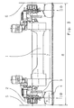
- Fig. 1
- eine Starrachse für Nutzfahrzeuge für ein schmales Fahrzeug;
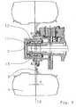
- Fig. 2
- einen Ausschnitt der Achse nach Fig. 1;
- Fig. 3
- eine Achse für Nutzfahrzeuge für breite Fahrzeuge und
- Fig. 4
- einen Ausschnitt der Achse nach Fig. 3.
- Ein Achsmittelteil 1 steht mit Radnaben 2 in Verbindung, an welche eine Felge 3 mit darauf angeordneten Reifen 4 befestigt ist. Die Fahrzeugbreite ist durch die Linie 5 und 6 angedeutet. Die Länge 7 des Achsmittelteils 1 ist so ausgelegt, dass die Gesamtbreite 8 der Achse nahezu der Fahrzeugbreite, welche durch die Linien 5 und 6 angedeutet ist, entspricht. Hierzu ist zusätzlich die Einpreßtiefe 9 der Felge 3 und die Breite des Reifens 4 bei der Auslegung mitberücksichtigt.
- Eine Felge 3 ist mit der Radnabe 2 verbunden und trägt den Reifen 4. Die Einpreßtiefe 9 sowie die Breite des Reifens 4 sind so ausgelegt, dass eine Radaufstandskraft 10 innerhalb der Druckpunktlinien 11 und 12 des Radlagers 13 angeordnet ist, so dass die Radlager 13 eine ausreichende Lebensdauer aufweisen.
- Ein Achsmittelteil 1 steht mit den Radnaben 2 in Verbindung. Auf den Radnaben 2 sind die Felge 3 und die Reifen 4 angeordnet. Die Fahrzeugbreite wird durch die Linien 5 und 6 schematisch dargestellt. Die Breite des Reifens 4, die Einpreßtiefe 9 der Felge 3 sowie die Länge 7 des Achsmittelteils 1 sind so ausgelegt, dass die Gesamtbreite 8 der Achse nahezu der Gesamtbreite des Fahrzeugs, dargestellt durch die Linien 5 und 6, entspricht.
- Die Einpreßtiefe 9 und die Breite des Reifens 4 sind so ausgelegt, dass die Radaufstandskraft 10 innerhalb der Druckpunktlinien 11 und 12 des Radlagers 13 so angeordnet ist, dass die Radlager 13 eine ausreichende Lebensdauer aufweisen. Durch die Auslegung der Länge 7 des Achsmittelteils 1 der Einpreßtiefe 9 und der Breite des Reifens 4 ist es möglich, alle wesentlichen Bauteile der Achse, insbesondere das Achsmittelteil 1, auch für unterschiedliche Fahrzeugbreiten gleich zu belassen.
-
- 1
- Achsmittelteil
- 2
- Radnaben
- 3
- Felge
- 4
- Reifen
- 5
- Linie
- 6
- Linie
- 7
- Länge
- 8
- Gesamtbreite
- 9
- Einpreßtiefe
- 10
- Radaufstandskraft
- 11
- Druckpunktlinien
- 12
- Druckpunktlinien
- 13
- Radlager
Claims (3)
- Achse für Nutzfahrzeuge mit einem Achsmittelteil (1), Radnaben (2), Radlager (13) und mit auf den Radnaben (2) anbringbaren Felgen (3), mit verschiedenen definierten Einpreßtiefen (9) und auf den Felgen (3) montierbaren Reifen (4) mit verschiedenen definierten Breiten und einer durch die Bauteile der Achse (8); der Felgen (3) und Reifen (4) bestimmten Gesamtbreite (8), wobei bei Anwendung der Achse in mindestens zwei in ihrer Breite deutlich unterschiedlichen Nutzfahrzeugen die Länge (7) des Achsmittelteils (1) so bestimmt wird, dass die für die jeweiligen Nutzfahrzeuge benötigte Gesamtbreite der Achse (8) ausschließlich durch Veränderung der Einpreßtiefe (9) der Felgen (2) und der Reifenbreite erreichbar ist.
- Achse für Nutzfahrzeuge nach Anspruch 1, dadurch gekennzeichnet, dass die Länge (7) des Achsmittelteils (1) so bestimmt wird, dass bei den definierten Einpreßtiefen (9) und Reifenbreiten eine Radaufstandskraft (10) innerhalb von Druckpunktlinien (11, 12) der jeweiligen Radlager (13) angeordnet ist.
- Achse für Nutzfahrzeuge nach Anspruch 2, dadurch gekennzeichnet, dass die Länge (7) des Achsmittelteils (1) so definiert ist, dass bei Verwendung unterschiedlicher Reifen (4) und Felgeneinpreßtiefen (9) eine nahezu gleiche Lebensdauer der Radlager (13) erreicht wird.
Applications Claiming Priority (3)
| Application Number | Priority Date | Filing Date | Title |
|---|---|---|---|
| DE2002111472 DE10211472A1 (de) | 2002-03-15 | 2002-03-15 | Achse für Nutzfahrzeuge |
| DE10211472 | 2002-03-15 | ||
| PCT/EP2003/002457 WO2003078180A1 (de) | 2002-03-15 | 2003-03-11 | Achse für nutzfahrzeuge |
Publications (2)
| Publication Number | Publication Date |
|---|---|
| EP1485263A1 EP1485263A1 (de) | 2004-12-15 |
| EP1485263B1 true EP1485263B1 (de) | 2007-06-27 |
Family
ID=27771342
Family Applications (1)
| Application Number | Title | Priority Date | Filing Date |
|---|---|---|---|
| EP03720326A Expired - Lifetime EP1485263B1 (de) | 2002-03-15 | 2003-03-11 | Achse für nutzfahrzeuge |
Country Status (3)
| Country | Link |
|---|---|
| EP (1) | EP1485263B1 (de) |
| DE (2) | DE10211472A1 (de) |
| WO (1) | WO2003078180A1 (de) |
Cited By (1)
| Publication number | Priority date | Publication date | Assignee | Title |
|---|---|---|---|---|
| US11560017B2 (en) | 2017-07-12 | 2023-01-24 | Axletech International Ip Holdings, Llc | Adjustable axle assembly for a vehicle |
Families Citing this family (2)
| Publication number | Priority date | Publication date | Assignee | Title |
|---|---|---|---|---|
| DE102004003650B4 (de) * | 2004-01-24 | 2017-02-16 | Zf Friedrichshafen Ag | Portalachse |
| DE102004062343A1 (de) * | 2004-12-20 | 2006-06-29 | Claus Giebel | Radkonfigurierverfahren |
Family Cites Families (3)
| Publication number | Priority date | Publication date | Assignee | Title |
|---|---|---|---|---|
| DE3801640C1 (de) * | 1988-01-21 | 1989-01-26 | Dr.Ing.H.C. F. Porsche Ag, 7000 Stuttgart, De | |
| EP0599293B2 (de) * | 1992-11-27 | 2000-05-31 | Magyar Vagon-Es Gepgyar | Achse für Fahrzeuge |
| DE19920670A1 (de) * | 1999-05-05 | 2000-11-23 | Man Nutzfahrzeuge Ag | Achskörper einer Vorlauf-, Nachlauf- oder Liftachse für Nutzfahrzeuge |
-
2002
- 2002-03-15 DE DE2002111472 patent/DE10211472A1/de not_active Withdrawn
-
2003
- 2003-03-11 DE DE50307564T patent/DE50307564D1/de not_active Expired - Lifetime
- 2003-03-11 WO PCT/EP2003/002457 patent/WO2003078180A1/de not_active Ceased
- 2003-03-11 EP EP03720326A patent/EP1485263B1/de not_active Expired - Lifetime
Non-Patent Citations (1)
| Title |
|---|
| None * |
Cited By (1)
| Publication number | Priority date | Publication date | Assignee | Title |
|---|---|---|---|---|
| US11560017B2 (en) | 2017-07-12 | 2023-01-24 | Axletech International Ip Holdings, Llc | Adjustable axle assembly for a vehicle |
Also Published As
| Publication number | Publication date |
|---|---|
| DE50307564D1 (de) | 2007-08-09 |
| DE10211472A1 (de) | 2003-09-25 |
| WO2003078180A1 (de) | 2003-09-25 |
| EP1485263A1 (de) | 2004-12-15 |
Similar Documents
| Publication | Publication Date | Title |
|---|---|---|
| DE102014009454B4 (de) | Radnabe für eine Fahrzeugachse | |
| EP1094957A1 (de) | Fahrzeugrad mit einem notlaufstützkörper | |
| EP2222972B1 (de) | Radlagerung eines flugzeugfahrwerks | |
| EP2239155A1 (de) | Achskonstruktion für ein Fahrzeug, insbesondere für ein Nutzfahrzeug | |
| DE102010049797A1 (de) | Radnabe und Bremsscheibe | |
| EP1024966A1 (de) | Geschweisstes fahrzeugrad | |
| DE60101498T2 (de) | Radaufhängung an Achsbrücke oder Achse für Motorfahrzeuge | |
| EP2655086A2 (de) | Fahrzeugrad für nutzfahrzeuge | |
| DE19840006A1 (de) | Flurförderzeug, insbesondere Hubgabelstapler, und zugeordnete Achs-Motor-Einheit | |
| DE102005043091B4 (de) | Radlageranordnung mit einer Luftleitvorrichtung | |
| DE10211472A1 (de) | Achse für Nutzfahrzeuge | |
| DE102004037266A1 (de) | Antriebsachse mit einem Elektromotor und integriertem Differentialgetriebe | |
| DE102007011025A1 (de) | Anordnung zur Beeinflussung einer Auflagefläche eines Fahrzeugreifens | |
| DE2716737A1 (de) | Sicherheits-reifenabstuetzung fuer eine radfelge | |
| EP1409323A1 (de) | Antriebseinheit zum antrieb mindestens einer radantriebswelle, insbesondere einer radsatzwelle | |
| DE29918476U1 (de) | Fahrzeugrad für Nutzfahrzeuge | |
| DE4408140C1 (de) | Breitreifenrad für ein Kraftfahrzeug | |
| DE10259156B4 (de) | Radnabe für die Lagerung eines Fahrzeugsrades | |
| EP1149009B1 (de) | Losradachse für schienenfahrzeuge | |
| DE19721860A1 (de) | Geschweißtes Fahrzeugrad | |
| DE2926445A1 (de) | Scheibenrad fuer strassenfahrzeuge | |
| DE10037562A1 (de) | Ein Sicherheitsreifenradsystem mit einem oder mehreren Reifen auf einer Felge und Einspeiskanälen in den Speichen der Felge und Einspeisventilen in der Nähe der Drehachse des Rades | |
| DE69902060T2 (de) | Antriebsvorrichtung und lageranordnung für eine trommel | |
| DE19709576B4 (de) | Zwillingsrad | |
| DE102010001695A1 (de) | Radbefestigungsanordnung |
Legal Events
| Date | Code | Title | Description |
|---|---|---|---|
| PUAI | Public reference made under article 153(3) epc to a published international application that has entered the european phase |
Free format text: ORIGINAL CODE: 0009012 |
|
| 17P | Request for examination filed |
Effective date: 20040728 |
|
| AK | Designated contracting states |
Kind code of ref document: A1 Designated state(s): AT BE BG CH CY CZ DE DK EE ES FI FR GB GR HU IE IT LI LU MC NL PT RO SE SI SK TR |
|
| RBV | Designated contracting states (corrected) |
Designated state(s): DE HU IT |
|
| GRAP | Despatch of communication of intention to grant a patent |
Free format text: ORIGINAL CODE: EPIDOSNIGR1 |
|
| GRAS | Grant fee paid |
Free format text: ORIGINAL CODE: EPIDOSNIGR3 |
|
| GRAA | (expected) grant |
Free format text: ORIGINAL CODE: 0009210 |
|
| AK | Designated contracting states |
Kind code of ref document: B1 Designated state(s): DE HU IT |
|
| REF | Corresponds to: |
Ref document number: 50307564 Country of ref document: DE Date of ref document: 20070809 Kind code of ref document: P |
|
| REG | Reference to a national code |
Ref country code: HU Ref legal event code: AG4A Ref document number: E002169 Country of ref document: HU |
|
| PLBE | No opposition filed within time limit |
Free format text: ORIGINAL CODE: 0009261 |
|
| STAA | Information on the status of an ep patent application or granted ep patent |
Free format text: STATUS: NO OPPOSITION FILED WITHIN TIME LIMIT |
|
| 26N | No opposition filed |
Effective date: 20080328 |
|
| PGFP | Annual fee paid to national office [announced via postgrant information from national office to epo] |
Ref country code: HU Payment date: 20120227 Year of fee payment: 10 |
|
| PGFP | Annual fee paid to national office [announced via postgrant information from national office to epo] |
Ref country code: IT Payment date: 20120319 Year of fee payment: 10 |
|
| PGFP | Annual fee paid to national office [announced via postgrant information from national office to epo] |
Ref country code: DE Payment date: 20120411 Year of fee payment: 10 |
|
| REG | Reference to a national code |
Ref country code: DE Ref legal event code: R119 Ref document number: 50307564 Country of ref document: DE Effective date: 20131001 |
|
| PG25 | Lapsed in a contracting state [announced via postgrant information from national office to epo] |
Ref country code: DE Free format text: LAPSE BECAUSE OF NON-PAYMENT OF DUE FEES Effective date: 20131001 |
|
| PG25 | Lapsed in a contracting state [announced via postgrant information from national office to epo] |
Ref country code: HU Free format text: LAPSE BECAUSE OF NON-PAYMENT OF DUE FEES Effective date: 20130312 Ref country code: IT Free format text: LAPSE BECAUSE OF NON-PAYMENT OF DUE FEES Effective date: 20130311 |