EP1484536B1 - Mischarmatur - Google Patents
Mischarmatur Download PDFInfo
- Publication number
- EP1484536B1 EP1484536B1 EP04002629A EP04002629A EP1484536B1 EP 1484536 B1 EP1484536 B1 EP 1484536B1 EP 04002629 A EP04002629 A EP 04002629A EP 04002629 A EP04002629 A EP 04002629A EP 1484536 B1 EP1484536 B1 EP 1484536B1
- Authority
- EP
- European Patent Office
- Prior art keywords
- mixing valve
- valve according
- stops
- spindles
- mixer housing
- Prior art date
- Legal status (The legal status is an assumption and is not a legal conclusion. Google has not performed a legal analysis and makes no representation as to the accuracy of the status listed.)
- Expired - Lifetime
Links
Images






Classifications
-
- E—FIXED CONSTRUCTIONS
- E03—WATER SUPPLY; SEWERAGE
- E03C—DOMESTIC PLUMBING INSTALLATIONS FOR FRESH WATER OR WASTE WATER; SINKS
- E03C1/00—Domestic plumbing installations for fresh water or waste water; Sinks
- E03C1/02—Plumbing installations for fresh water
- E03C1/04—Water-basin installations specially adapted to wash-basins or baths
- E03C1/0412—Constructional or functional features of the faucet handle
-
- E—FIXED CONSTRUCTIONS
- E03—WATER SUPPLY; SEWERAGE
- E03C—DOMESTIC PLUMBING INSTALLATIONS FOR FRESH WATER OR WASTE WATER; SINKS
- E03C1/00—Domestic plumbing installations for fresh water or waste water; Sinks
- E03C1/02—Plumbing installations for fresh water
- E03C1/04—Water-basin installations specially adapted to wash-basins or baths
-
- F—MECHANICAL ENGINEERING; LIGHTING; HEATING; WEAPONS; BLASTING
- F16—ENGINEERING ELEMENTS AND UNITS; GENERAL MEASURES FOR PRODUCING AND MAINTAINING EFFECTIVE FUNCTIONING OF MACHINES OR INSTALLATIONS; THERMAL INSULATION IN GENERAL
- F16K—VALVES; TAPS; COCKS; ACTUATING-FLOATS; DEVICES FOR VENTING OR AERATING
- F16K11/00—Multiple-way valves, e.g. mixing valves; Pipe fittings incorporating such valves
- F16K11/02—Multiple-way valves, e.g. mixing valves; Pipe fittings incorporating such valves with all movable sealing faces moving as one unit
- F16K11/06—Multiple-way valves, e.g. mixing valves; Pipe fittings incorporating such valves with all movable sealing faces moving as one unit comprising only sliding valves, i.e. sliding closure elements
- F16K11/072—Multiple-way valves, e.g. mixing valves; Pipe fittings incorporating such valves with all movable sealing faces moving as one unit comprising only sliding valves, i.e. sliding closure elements with pivoted closure members
- F16K11/074—Multiple-way valves, e.g. mixing valves; Pipe fittings incorporating such valves with all movable sealing faces moving as one unit comprising only sliding valves, i.e. sliding closure elements with pivoted closure members with flat sealing faces
Definitions
- the invention relates to a mixing valve with a mixer housing, in which two rotatable spindles are arranged whose rotation angle is limited by stops and each of which is in engagement with a control disk, which in each case is in contact with a rotationally fixed inlet disk, which has at least one passage opening,
- Mixing valves are used to control the discharge of media from fittings.
- cold and hot water mixing valves versions are known both with two screw caps as well as single lever mixer.
- fittings with two screw caps have the advantage that there is a clear separation between hot and cold water metering.
- they are either handled with only two hands or one hand by grasping.
- Single-lever mixers allow a simultaneous dosing of the cold and hot water supply, whereby the mixing ratio is usually changed by turning the lever and the dosage of the amount of water is done by a lever tilt. In this case, a rotation and an inclination of the lever can take place simultaneously.
- This simultaneous Controlling the amount of water and the mixing ratio by a three-dimensional lever movement has the consequence that often a jerky opening of the water supply with extreme water temperature (very hot / very cold) is observed.
- a fitting of the type mentioned is known from DE 196 35 614 C1.
- the known fitting has a housing in which two chambers are formed.
- the chambers receive two valve shut-off members, which are formed by stationary disks and rotatable disks, each having at least one passage opening.
- the valve shut-off members are operable by a common actuator by means of a pinion by rotation about parallel axes. The angle of rotation of the actuator is limited by a approach.
- a mixing valve comprising a housing and two operating handles.
- On the armature is a mounting thread shaft which receives supply lines, and provided coaxially with outlets an inner part which is provided with an external thread on which a Ventilschaftnuss is screwed. Since the nut is mounted axially fixed, takes place when operating the handles an axial movement of a non-rotatable valve stem. Depending on the direction of movement of the handles, the valve stem moves with its inner part in the direction of an outlet or in the opposite direction.
- a switch is known which comprises a cylindrical housing and a rotatable valve.
- a drive shaft which penetrates the housing; also a seat in the housing.
- an annular wheel is provided, which has movable guides.
- a valve tongue is guided, which is connected to the drive shaft by a gear which holds the valve tongue pressed against its seat.
- the transmission axially lifts the valve tongue out of the seat until the valve tongue is held against the ring gear.
- a mixing valve is created, which allows a comfortable one-hand operation and also clearly displays the mixing ratio of the media. Since the spindles are provided with bores for receiving ball pins that fit into ball seats of the drive rings, a reliable motion transmission from the handles to the spindles is caused. In addition, a cost-effective production is possible and an operation with little effort realized. The transmission of motion is smooth, as there are no interlocking tongues.
- the stops are arranged on the outer region of the mixer housing. This ensures that the handles are exactly on top of each other and have a rotation angle of 60 ° or 40 °.
- the attacks are formed by passport or grooved pins.
- these are used in bores of a body.
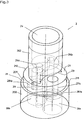
- the mixing fitting 1 selected as an exemplary embodiment consists of a mixer housing 2, into which two spindles 3a, b are inserted.
- two rotary levers 4a, b are provided on the mixing fitting, the movement of which can be transferred to the spindles in a form-fitting manner.
- a solder nipple 5 is partially inserted into the mixer housing 2, which is held via a head nut 6 and to which an outlet pipe 7 is arranged.
- the mixing valve is connected to a flange 8 in connection.
- the mixer housing 2 is designed rotationally symmetrical. It consists of a body 20, which is composed of three superimposed cylinders 200, 201, 202.
- the cylinders 200, 201, 202 have different diameters, wherein the flange 20 facing the cylinder 200 has the largest diameter, the middle cylinder 201 has a smaller diameter in relation to the cylinder 200 and the flange 202 facing away from the cylinder has the smallest diameter. Due to the different diameters paragraphs 21 are formed between the cylinders, which are referred to as stop surfaces 211 and 212.
- the mixing fitting 2 is provided with an external thread 22, which corresponds in the mounted state with the head nut 6. From the side facing away from the flange 8, a bore 24 is introduced into the mixing fitting 2, which has a bottom 241. At its end remote from the bottom 241, a groove 242 is formed in the bore.
- two mutually opposite cut-outs 23 are provided in the cylinder 202.
- the cutouts 23 are each in the form of a circle segment, for which reason the web 231 has a concave shape in plan view (FIGS. 4, 5, 10, 13 and 14).
- bores 29 are introduced into the cylinder 201, adjacent to the web 23, which receive stops 97 (FIG. 11).
- the stops 97 may be formed, for example in the form of notched or dowel pins.
- the web 231 and the cylinders 200 and 201 are penetrated by two holes 26 a, b.
- the bores 26a, b extend from the flange 8 facing the end of the cylinder 200 to the bottom 241 of the bore 24, in which the bores 26a, b open.
- the bores 26a, b are aligned parallel to one another and arranged opposite one another on one of the transverse centerlines of the mixing housing 2.
- the cylinders 200 and 201 are further penetrated by two holes 27 a, b.
- the bores 27a, b are offset by 90 ° relative to the bores 26a, b (FIGS. 4, 5, 9, 10, 13 and 14).
- the bores 27a, b extend from the end of the mixing fitting 2 facing the flange 8 into the area of the cutouts 13 in the amount of the stop surfaces 212 of the cylinder 201.
- grooves 271 and 27 are respectively provided in the bores 27a, b 272 trained.
- the Groove 271 serves to receive an inlet disc 92; the groove 272 receiving a lip seal 93.
- the holes 27a, b are made in the region of the cylinder 200 discontinued, whereby holes 28a, b are caused with larger diameter.
- stop surfaces 281 a, b are formed.
- connecting chambers 282a, b are arranged, which are crescent-shaped in plan view ( Figures 7 to 10).
- the chambers 282a, b ends the holes 26a, b, so that a connection between the holes 26a, b and 28a, b is caused.
- the spindles 3a, b are arranged in the bores 27a, b. They each have a spindle head 31a, b at their end remote from the flange 8.
- the spindle heads 31 a, b are provided in the embodiment of Figures 2, 4 and 5 with a toothing 311 a, b; in the embodiment of Figures 12, 13 and 14, the spindle heads 31 a, b are gearless and provided with a radial bore 312 a, b for receiving a ball pin 313 a, b, which is arranged movably in the bore 312 a, b.
- the spindle heads 31a, b protrude into the area of the cutouts 23.
- the spindles 3a, b are provided with a cutout 32a, b.
- the free cut 32a, b is followed by a respective cylinder 33a, b, which is interrupted by two annular grooves 34a, b for receiving O-rings 95, by means of which the spindles 3a, b are sealed against the mixer housing 2.
- a larger diameter control cylinder with drivers 35a, b is formed on the spindles 3a, b.
- a stop surface 36a, b is caused, which rests against the stop surface 28a, b of the mixer housing 2 with the interposition of a sliding disk 94.
- the drivers 35a, b serve to actuate the control disk 91st
- the rotary levers 4a, b are performed substantially in the manner of a hollow cylinder 41 a, b.
- the hollow cylinder can be seen as an annular part, to each of which a handle 43 a, b is formed.
- the handles 43a, b are formed as pins; they are beyond can also be realized in the form of wings (FIGS. 2 and 12).
- the hollow cylinder 41 a, b include the paragraphs 201 and 202 of the mixer housing 2.
- a drive ring 42a is formed inside the hollow cylinder 41 a, the arc length corresponds to one third of the inner circumference of the hollow cylinder 41 a.
- the drive ring 42a forms a groove 411 with the hollow cylinder 41 a.
- the hollow cylinder 41 b of the rotary lever 4 b has an internal diameter, which is equal to the inner diameter of the hollow cylinder 41 a.
- the hollow cylinder 41 b is disposed immediately adjacent to the hollow cylinder 41 a.
- a collar 412 is formed, which engages in the groove 411 of the rotary lever 4a.
- a drive ring 42b is arranged on the drive ring 42a of the rotary lever 4a side facing away from the collar 412.
- the collar 412 including the drive collar 42b forms with the hollow cylinder 41b a groove 413, into which the hollow cylinder 41a is inserted with its end facing away from the flange 8.
- the arc length of the drive ring 42b corresponds to that of the drive ring 42a.
- Both drive rings 42a, b have at their ends in each case a stop recess 421.
- the stop recesses 421 correspond to the stops 97.
- the interaction of the stop recesses 421 with the stops 97 of the rotation angle of the rotary lever 4a, b is limited to 60 ° or 40 °. Due to the selected geometry, a contact of the stop recesses 421 of the drive rings 42a, b on the respectively opposite stop 97 leads to a position of the handles 43 aligned exactly one above the other (FIGS. 1, 2, 12). This results from the arrangement as an outer stop - in the exemplary embodiment by the arrangement of the stops 97 between the cylinder 202 of the mixer housing 2 and the hollow cylinders 41 a, b on the outermost region of the stop surface 212th
- the drive rings 42a, b with a toothing 422a, b are provided, which engage in the assembled state in the teeth 311a, b of the spindles 3a, b.
- the teeth 422a, b are formed as a degree of toothing.
- a ball seat 423a, b is provided in the drive rings 42a, b, respectively, into which Grasp the ball pins 313a, b.
- the ball pins 313a, b are movably supported in the ball seats 323a, b.
- the Lotnippel 5 is inserted into the bore 24 of the mixer housing 2. It is rotationally symmetrical and has approximately centrally a collar 51 which rests in the mounted state in the groove 242 of the bore 24. At its end remote from the flange 8, the solder nipple 5 is externally provided with a chamfer 52. Adjacent to the chamfer 52, an annular groove 53 is arranged. On the side facing the flange 8, the solder nipple 5 is cylindrically formed following the collar 51, wherein two annular grooves 54 are provided for receiving O-rings 96. With the help of the O-rings 96 of the Lotnippel 5 is sealed against the mixer housing 2.
- the Lotnippel 5 is penetrated by a bore 55 which is divided into two regions of different diameters.
- the region of larger diameter serves as a mixing chamber 551, to which an outlet 552, which has a smaller diameter than the mixing chamber 551, connects.
- the free end of Lotnippels 5 serves to receive the outlet pipe 7, wherein the chamfer 52 facilitates slipping over of the tube 7.
- the flange 8 facing the end of the outlet pipe 7 is supported in the assembled state on the collar 51 from.
- the head nut 6 is rotationally symmetrical. It has, on the outside, a guide 61 in which the hollow cylinder 41b of the rotary lever 4b is guided. Inside it is provided with a thread 62 which corresponds to the external thread 22 of the mixer housing 2. The screwing of the nut 6 causes a fixation of the Lotnippels 5 with outlet pipe 7 and the rotary lever 4a, b to the mixer housing. 2
- the flange 8 has two bores 81 a, b, which are provided with integrated connections for hot and cold water.
- the bores 81a, b are aligned with the bores 27a, b of the mixer housing 2.
- the bore 81 a serves as a hot water inlet; the bore 81 b as a cold water inlet.
- In the region of the mixer housing 2 facing the end of the flange 8 is provided with flat support surfaces 82a, b.
- the bearing surfaces 82a, b are in contact with the lip seals 93, which are formed in a conventional manner.
- the control discs 91 are rotatably in the spindles 3a, b arranged. They each have a passage opening 911.
- the control discs 91 are made of ceramic.
- the inlet discs 92 are rotatably disposed in the mixer housing 2. They also have passage openings 921 and are preferably also made of ceramic. On the side facing the flange 8, the inlet disks 92 are in sealed contact with the lip seals 93.
- the spindle 3a together with the control disk 91 received by the driver 35 is rotated in the same direction via the combination of the teeth 311a / 422a or the combination ball pin 313a / ball seat 423a, whereby the passage opening 911 of the control disk 91st is moved via the passage opening 921 of the inlet disk 92.
- the water now flows past the driver 35a into the bore 28a.
- the water reaches from there the connecting chamber 282a and flows through the bores 26a and 24 of the mixer housing 2 via the bore 55 of the Lotnippels 5 in the outlet pipe 7.
Landscapes
- Engineering & Computer Science (AREA)
- Health & Medical Sciences (AREA)
- Life Sciences & Earth Sciences (AREA)
- Hydrology & Water Resources (AREA)
- Public Health (AREA)
- Water Supply & Treatment (AREA)
- General Engineering & Computer Science (AREA)
- Mechanical Engineering (AREA)
- Multiple-Way Valves (AREA)
- Mixers Of The Rotary Stirring Type (AREA)
- Preparation Of Clay, And Manufacture Of Mixtures Containing Clay Or Cement (AREA)
Description
- Die Erfindung betrifft eine Mischarmatur mit einem Mischergehäuse, in dem zwei drehbare Spindeln angeordnet sind, deren Drehwinkel durch Anschläge begrenzt sind und die jeweils mit einer Steuerscheibe im Eingriff stehen, welche jeweils mit einer drehfesten Einlassscheibe in Berührung steht, die mindestens eine Durchtrittsöffnung aufweist,
- Mit Hilfe von Mischarmaturen wird der Austritt von Medien aus Armaturen gesteuert. Bei Kalt- und Warmwasser-Mischarmaturen sind Ausführungen sowohl mit zwei Drehverschlüssen als auch mit Einhandhebelmischer bekannt. Armaturen mit zwei Drehverschlüssen haben den Vorteil, dass eine deutliche Trennung zwischen Warm- und Kaltwasserdosierung besteht Sie sind jedoch entweder nur mit zwei Händen oder einhändig durch umgreifen zu bedienen. Außerdem fehlt in der Regel eine optische Orientierung hinsichtlich des erzielten Mischungsverhältnisses. Einhandhebelmischer ermöglichen eine gleichzeitige Dosierung des Kalt- und Warmwasserzulaufs, wobei das Mischungsverhältnis in der Regel durch Drehen des Hebels verändert wird und die Dosierung der Wassermenge durch eine Hebelneigung erfolgt. Dabei kann eine Drehung sowie eine Neigung des Hebels gleichzeitig erfolgen. Diese gleichzeitige Steuerung der Wassermenge sowie des Mischungsverhältnisses durch eine dreidimensionale Hebelbewegung hat zur Folge, dass häufig ein ruckartiges Öffnen der Wasserzufuhr mit extremer Wassertemperatur (sehr heiss/sehr kalt) zu beobachten ist.
- Eine Armatur der eingangs genannten Art ist aus DE 196 35 614 C1 bekannt. Die bekannte Armatur weist ein Gehäuse auf, in dem zwei Kammern ausgebildet sind. Die Kammern nehmen zwei Ventilabsperrglieder auf, die von ortsfesten Scheiben und drehbaren Scheiben gebildet sind, die jeweils mindestens eine Durchgangsöffnung aufweisen. Die Ventilabsperrglieder sind durch ein gemeinsames Betätigungsglied mittels eines Zahntriebs durch Drehung um parallele Achsen betätigbar. Der Drehwinkel des Betätigungsgliedes ist durch einen Ansatz begrenzt.
- Aus US-A 4 074 697 ist weiterhin eine Mischarmatur bekannt, die ein Gehäuse und zwei Betätigungsgriffe aufweist. An der Armatur ist ein Montagegewindeschaft, der Zulaufleitungen aufnimmt, und koaxial zu Ausläufen ein Innenteil vorgesehen, das mit einem Außengewinde versehen ist, auf welches eine Ventilschaftnuss aufgeschraubt ist. Da die Nuss axial fest montiert ist, erfolgt bei Betätigung der Griffe eine axiale Bewegung eines drehfesten Ventilschaftes. In Abhängigkeit der Bewegungsrichtung der Griffe bewegt sich der Ventilschaft mit seinem Innenteil in Richtung eines Auslaufs bzw. in die abgewandte Richtung. Schließlich ist aus US-A 4 770 392 ein Schalter bekannt, der ein zylinderförmiges Gehäuse und ein drehbares Ventil aufweist. Für das Ventil ist ein Antriebsschaft vorgesehen, der das Gehäuse durchdringt; außerdem ein Sitz in dem Gehäuse. Auf dem Antriebsschaft ist ein ringförmiges Rad vorgesehen, welches bewegbare Führungen aufweist. In dem Ringrad ist eine Ventilzunge geführt, die mit dem Antriebsschaft durch ein Getriebe verbunden ist, welches die Ventilzunge auf ihren Sitz gedrückt hält. Wenn der Antriebsschaft sich zurückbewegt, hebt das Getriebe die Ventilzunge axial aus dem Sitz hoch, bis die Ventilzunge an dem Ringrad gehalten ist.
- Mit der Erfindung soll eine Mischarmatur der gattungsgemäßen Art so ausgebildet werden, dass einerseits eine komfortable Einhandbedienung ermöglicht und das Mischungsverhältnis der Medien deutlich angezeigt wird, andererseits eine zuverlässige Bewegungsübertragung von den Griffen auf die Spindel hervorgerufen und eine kostengünstige Herstellung wegen des Verzichts auf die Erstellung von Verzahnungen ermöglicht ist. Zudem soll bei geringem Kraftaufwand eine ruckfreie Betätigung ermöglicht werden. Gemäß der Erfindung wird diese Aufgabe durch die Merkmale des Patentanspruchs 1 gelöst.
- Mit der Erfindung ist eine Mischarmatur geschaffen, die eine komfortable Einhandbedienung ermöglicht und darüber hinaus das Mischungsverhältnis der Medien deutlich anzeigt. Da die Spindeln mit Bohrungen zur Aufnahme von Kugelstiften versehen sind, die in Kugelsitze der Antriebskränze fassen, ist eine zuverlässige Bewegungsübertragung von den Griffen auf die Spindeln hervorgerufen. Zudem ist eine kostengünstige Herstellung möglich und eine Betätigung mit geringem Kraftaufwand realisierbar. Die Bewegungsübertragung erfolgt ruckfrei, da keine ineinander greifenden Zungen vorhanden sind.
- In Weiterbildung der Erfindung sind die Anschläge auf dem äußeren Bereich des Mischergehäuses angeordnet. Hierdurch ist gewährleistet, dass die Griffe genau übereinander liegen und einen Drehwinkel von 60° oder 40° haben.
- In Ausgestaltung der Erfindung sind die Anschläge durch Pass- oder Kerbstifte gebildet. Bevorzugt sind diese in Bohrungen eines Körpers eingesetzt. Hierdurch sind auf einfache und damit preiswerte Art und Weise Anschläge zur Drehbegrenzung hervorgerufen.
- Andere Weiterbildungen und Ausgestaltungen der Erfindung sind in den übrigen Unteransprüchen angegeben. Ein Ausführungsbeispiel der Erfindung ist in den Zeichnungen dargestellt und wird nachfolgend im Einzelnen beschrieben. Es zeigen:
- Figur 1
- die dreidimensionale Darstellung einer Mischarmatur;
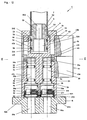
- Figur 2
- die in Figur 1 dargestellte Mischarmatur im Längsschnitt;
- Figur 3
- das Mischergehäuse der Mischarmatur in einer dreidimensionalen Darstellung;
- Figur 4
- den Schnitt entlang der Linie II-II in Figur 2 (Ventile geschlossen);
- Figur 5
- den Schnitt entlang der Linie II-II in Figur 2 (Ventile offen);
- Figur 6
- das Mischergehäuse der Mischarmatur im Längsschnitt;
- Figur 7
- das Mischergehäuse gemäß Figur 6 in der Draufsicht;
- Figur 8
- das Mischergehäuse gemäß Figur 6 in der Untersicht;
- Figur 9
- den Schnitt entlang der Linie A-B in Figur 6;
- Figur 10
- den Schnitt entlang der Linie C-D in Figur 6;
- Figur 11
- den Schnitt entlang der Linie E-F in Figur 8;
- Figur 12
- die in Figur 1 dargestellte Mischarmatur in anderer Ausgestaltung im Längsschnitt;
- Figur 13
- den Schnitt entlang der Linie III-III in Figur 12 (Ventile geschlossen) und
- Figur 14
- den Schnitt entlang der Linie III-III in Figur 12 (Ventile offen).
- Die als Ausführungsbeispiel gewählte Mischarmatur 1 besteht aus einem Mischergehäuse 2, in das zwei Spindeln 3a, b eingesetzt sind. Zur Betätigung sind an der Mischarmatur zwei Drehhebel 4a, b vorgesehen, deren Bewegung formschlüssig auf die Spindeln übertragbar ist. An seinem einen Ende ist in das Mischergehäuse 2 teilweise ein Lotnippel 5 eingesetzt, der über eine Kopfmutter 6 gehalten ist und an dem ein Auslaufrohr 7 angeordnet ist. An ihrem dem Auslaufrohr 7 abgewandten Ende steht die Mischarmatur mit einem Flansch 8 in Verbindung.
- Das Mischergehäuse 2 ist rotationssymmetrisch ausgeführt. Es besteht aus einem Körper 20, der aus drei übereinander angeordneten Zylindern 200, 201, 202 aufgebaut ist. Die Zylinder 200, 201, 202 weisen unterschiedliche Durchmesser auf, wobei der dem Flansch 8 zugewandten Zylinder 200 den grössten Durchmesser aufweist, der mittlere Zylinder 201 einen im Verhältnis zum Zylinder 200 kleineren Durchmesser und der dem Flansch abgewandte Zylinder 202 den kleinsten Durchmesser hat. Auf Grund der unterschiedlichen Durchmesser sind zwischen den Zylindern Absätze 21 ausgebildet, die als Anschlagflächen 211 und 212 bezeichnet sind.
- An seinem dem Flansch 8 abgewandten Ende ist die Mischarmatur 2 mit einem Aussengewinde 22 versehen, das in montiertem Zustand mit der Kopfmutter 6 korrespondiert. Von der dem Flansch 8 abgewandten Seite ist in die Mischarmatur 2 eine Bohrung 24 eingebracht, die einen Boden 241 aufweist. An ihrem dem Boden 241 abgewandten Ende ist in der Bohrung eine Nut 242 ausgebildet.
- An dem dem Zylinder 201 zugewandten Ende sind in dem Zylinder 202 zwei sich gegenüberliegende Ausfräsungen 23 vorgesehen. Durch die Ausfräsungen 23 ist ein Steg 231 ausgebildet. Die Ausfräsungen 23 haben jeweils die Form eines Kreissegments, weshalb der Steg 231 in der Draufsicht eine konkave Form aufweist (Fig. 4, 5, 10, 13 und 14). Auf der Längsmittellinie des Steges 231 sind aussen benachbart zum Steg 231 Bohrungen 29 in den Zylinder 201 eingebracht, die Anschläge 97 aufnehmen (Fig. 11). Die Anschläge 97 können beispielsweise in Form von Kerb- oder Passstiften ausgebildet sein.
- Der Steg 231 sowie die Zylinder 200 und 201 sind durchsetzt von zwei Bohrungen 26a, b. Die Bohrungen 26a, b erstrecken sich von dem dem Flansch 8 zugewandten Ende des Zylinders 200 bis zu dem Boden 241 der Bohrung 24, in die die Bohrungen 26a, b münden. Die Bohrungen 26a, b sind parallel zueinander ausgerichtet und gegenüberliegend auf einer der Quer-Mittellinien des Mischgehäuses 2 angeordnet.
- Die Zylinder 200 und 201 sind weiterhin von zwei Bohrungen 27a, b durchsetzt. Die Bohrungen 27a, b sind um 90° versetzt zu den Bohrungen 26a, b angeordnet (Fig. 4, 5, 9, 10, 13 und 14). Die Bohrungen 27a, b erstrecken sich von dem dem Flansch 8 zugewandten Ende der Mischarmatur 2 bis in den Bereich der Ausfräsungen 13 in Höhe der Anschlagflächen 212 des Zylinders 201. An ihrem dem Flansch zugewandten Ende sind in den Bohrungen 27a, b jeweils Nuten 271 und 272 ausgebildet. Die Nut 271 dient der Aufnahme einer Einlassscheibe 92; die Nut 272 der Aufnahme einer Lippendichtung 93. Die Bohrungen 27a, b sind im Bereich des Zylinders 200 abgesetzt ausgeführt, wodurch Bohrungen 28a, b mit grösserem Durchmesser hervorgerufen sind. Am Übergang der Bohrungen 27a, b und 28a, b sind Anschlagflächen 281 a, b ausgebildet. In den Bohrungen 28a, b sind Verbindungskammern 282a, b angeordnet, die in der Draufsicht sichelförmig sind (Figuren 7 bis 10). In den Kammern 282a, b enden die Bohrungen 26a, b, sodass eine Verbindung zwischen den Bohrungen 26a, b und 28a, b hervorgerufen ist.
- Die Spindeln 3a, b sind in den Bohrungen 27a, b angeordnet. Sie weisen jeweils an ihren dem Flansch 8 abgewandten Ende einen Spindelkopf 31a, b auf. Die Spindelköpfe 31 a, b sind im Ausführungsbeispiel nach den Figuren 2, 4 und 5 mit einer Verzahnung 311a, b versehen; im Ausführungsbeispiel nach den Figuren 12, 13 und 14 sind die Spindelköpfe 31 a, b verzahnungslos und mit einer radialen Bohrung 312a, b für die Aufnahme eines Kugelstiftes 313a, b versehen, der in der Bohrung 312a, b beweglich angeordnet ist.
- In montiertem Zustand ragen die Spindelköpfe 31a, b in den Bereich der Ausfräsungen 23. Im Anschluss an die Spindelköpfe 31a, b sind die Spindeln 3a, b mit einem Freischnitt 32a, b versehen. An den Freischnitt 32a, b schliesst sich jeweils ein Zylinder 33a, b an, der unterbrochen ist von jeweils zwei Ringnuten 34a, b zur Aufnahme von O-Ringen 95, mit deren Hilfe die Spindeln 3a, b gegen das Mischergehäuse 2 abgedichtet sind. Im Anschluss an den Zylinder 33a, b ist an den Spindeln 3a, b ein im Durchmesser grösserer Steuerzylinder mit Mitnehmern 35a, b ausgebildet. Durch die Durchmessererweiterung ist eine Anschlagfläche 36a, b hervorgerufen, die an der Anschlagfläche 28a, b des Mischergehäuses 2 unter Zwischenschaltung einer Gleitscheibe 94 anliegt. Die Mitnehmer 35a, b dienen der Betätigung der Steuerscheibe 91.
- Die Drehhebel 4a, b sind im Wesentlichen nach Art eines Hohlzylinders 41 a, b ausgeführt. In der Draufsicht (Fig. 4, 5, 13 und 14) ist der Hohlzylinder als ringförmiger Teil zu erkennen, an den jeweils ein Griff 43a, b angeformt ist. Im Ausführungsbeispiel nach Figur 1 sind die Griffe 43a, b als Stifte ausgebildet; sie sind darüber hinaus auch in Form von Flügeln realisierbar (Fig. 2 und 12). Die Hohlzylinder 41 a, b umfassen die Absätze 201 und 202 des Mischergehäuses 2. Im Bereich der Ausfräsung 23 des Mischergehäuses 2 ist innen an dem Hohlzylinder 41 a ein Antriebskranz 42a ausgebildet, dessen Bogenlänge einem Drittel des inneren Kreisumfangs des Hohlzylinders 41 a entspricht. Der Antriebskranz 42a bildet mit dem Hohlzylinder 41 a eine Nut 411 aus. Der Hohlzylinder 41 b des Drehhebels 4b weist einen Innendruchmesser auf, der gleich dem Innendurchmesser des Hohlzylinders 41 a ist.
- Der Hohlzylinder 41 b ist unmittelbar benachbart zum Hohlzylinder 41 a angeordnet. An seiner dem Hohlzylinder 41 a zugewandten Seite ist innen an dem Hohlzylinder 41 b ein Bund 412 angeformt, der in die Nut 411 des Drehhebels 4a eingreift. Auf der dem Antriebskranz 42a des Drehhebels 4a abgewandten Seite ist an dem Bund 412 ein Antriebskranz 42b angeordnet. Der Bund 412 einschließlich des Antriebskranzes 42b bildet mit dem Hohlzylinder 41 b eine Nut 413, in die der Hohlzylinder 41a mit seinem dem Flansch 8 abgewandten Ende eingesetzt ist. Die Bogenlänge des Antriebskranzes 42b entspricht derjenigen des Antriebskranzes 42a.
- Beide Antriebskränze 42a, b weisen an ihren Enden jeweils eine Anschlagmulde 421 auf. Die Anschlagmulden 421 korrespondieren mit den Anschlägen 97. Durch das Zusammenspiel der Anschlagmulden 421 mit den Anschlägen 97 ist der Drehwinkel der Drehhebel 4a, b auf 60° oder 40° begrenzt. Auf Grund der gewählten Geometrie führt ein Anliegen der Anschlagmulden 421 der Antriebskränze 42a, b an dem jeweils gegenüberliegenden Anschlag 97 zu einer exakt übereinander ausgerichteten Stellung der Griffe 43 (Fig. 1, 2, 12). Dies resultiert aus der Anordnung als Aussenanschlag - im Ausführungsbeispiel durch die Anordnung der Anschläge 97 zwischen Zylinder 202 des Mischergehäuses 2 und den Hohlzylindern 41 a, b auf dem äussersten Bereich der Anschlagfläche 212.
- Im Ausführungsbeispiel nach den Figuren 2, 4 und 5 sind die Antriebskränze 42a, b mit einer Verzahnung 422a, b versehen, die in montiertem Zustand in die Verzahnungen 311a, b der Spindeln 3a, b eingreifen. Die Verzahnungen 422a, b sind als Gradverzahnungen ausgebildet. Im Ausführungsbeispiel nach den Figuren 12, 13 und 14 ist in den Antriebskränzen 42a, b jeweils ein Kugelsitz 423a, b vorgesehen, in die die Kugelstifte 313a, b fassen. Die Kugelstifte 313a, b sind in den Kugelsitzen 323a, b beweglich gehalten.
- Der Lotnippel 5 ist in die Bohrung 24 des Mischergehäuses 2 eingesetzt. Er ist rotationssymmetrisch ausgebildet und weist etwa mittig einen Bund 51 auf, der in montiertem Zustand in der Nut 242 der Bohrung 24 aufliegt. An seinem dem Flansch 8 abgewandten Ende ist der Lotnippel 5 aussen mit einer Fase 52 versehen. Benachbart zu der Fase 52 ist eine Ringnut 53 angeordnet. Auf der dem Flansch 8 zugewandten Seite ist im Anschluss an den Bund 51 der Lotnippel 5 zylindrisch ausgebildet, wobei zwei Ringnuten 54 zur Aufnahme von O-Ringen 96 vorgesehen sind. Mit Hilfe der O-Ringe 96 ist der Lotnippel 5 gegen das Mischergehäuse 2 abgedichtet. Der Lotnippel 5 ist von einer Bohrung 55 durchsetzt, die in zwei Bereiche unterschiedlichen Durchmessers aufgeteilt ist. Der Bereich grösseren Durchmessers dient dabei als Mischkammer 551, an den sich ein Auslauf 552, der einen kleineren Durchmesser als die Mischkammer 551 aufweist, anschliesst. Das freie Ende des Lotnippels 5 dient der Aufnahme des Auslaufrohrs 7, wobei die Fase 52 ein Überstülpen des Rohrs 7 erleichtert. Das dem Flansch 8 zugewandte Ende des Auslaufrohrs 7 stützt sich in montiertem Zustand auf dem Bund 51 ab.
- Die Kopfmutter 6 ist rotationssymmetrisch ausgebildet. Sie weist aussen eine Führung 61 auf, in der der Hohlzylinder 41 b des Drehhebels 4b geführt ist. Innen ist sie mit einem Gewinde 62 versehen, das mit dem Aussengewinde 22 des Mischergehäuses 2 korrespondiert. Das Aufschrauben der Mutter 6 bewirkt eine Fixierung des Lotnippels 5 mit Auslaufrohr 7 sowie der Drehhebel 4a, b an dem Mischergehäuse 2.
- Der Flansch 8 weist zwei Bohrungen 81a, b auf, die mit integrierten Anschlüssen für Warm- und Kaltwasser versehen sind. Die Bohrungen 81a, b fluchten mit den Bohrungen 27a, b des Mischergehäuses 2. Im Ausführungsbeispiel dient die Bohrung 81 a als Warmwasser-Zulauf; die Bohrung 81 b als Kaltwasser-Zulauf. Im Bereich des dem Mischergehäuses 2 zugewandten Endes ist der Flansch 8 mit ebenen Auflageflächen 82a, b versehen. Die Auflageflächen 82a, b stehen in Kontakt mit den Lippendichtungen 93, die in an sich bekannter Weise ausgebildet sind.
- Die Steuerscheiben 91 sind drehfest in den Spindeln 3a, b angeordnet. Sie weisen jeweils eine Durchlassöffnung 911 auf. Bevorzugt sind die Steuerscheiben 91 aus Keramik hergestellt. Die Einlassscheiben 92 sind drehfest in dem Mischergehäuse 2 angeordnet. Sie weisen ebenfalls Durchlassöffnungen 921 auf und sind bevorzugt ebenfalls aus Keramik hergestellt. Auf der dem Flansch 8 zugewandten Seite stehen die Einlassscheiben 92 mit den Lippendichtungen 93 abgedichtet in Berührung.
- In der Grundstellung "Mischarmatur geschlossen" stehen Steuerscheibe 91 und Einlassscheibe 92 der Spindeln 3a, b derart zueinander, dass die Durchlassöffnung 921 der jeweiligen Einlassscheibe 92 durch die zugeordnete Steuerscheibe 91 verschlossen ist. In dieser Stellung stehen die Griffe 43 der Drehhebel 4a, b exakt übereinander, wobei die Anschlagmulden 421 der Antriebskränze 42a, b gegenüberliegend an die Anschlagstifte 97 anschlagen. Wird der Griff 41 a im Uhrzeigersinn bewegt, so wird die Spindel 3a mit samt der vom Mitnehmer 35 aufgenommenen Steuerscheibe 91 über die Kombination der Verzahnungen 311a/422a bzw. die Kombination Kugelstift 313a/Kugelsitz 423a gleichgerichtet gedreht, wodurch die Durchlassöffnung 911 der Steuerscheibe 91 über die Durchlassöffnung 921 der Einlassscheibe 92 bewegt wird. Durch die Freigabe der Durchlassöffnungen strömt nun das Wasser an dem Mitnehmer 35a vorbei in die Bohrung 28a. Das Wasser erreicht von dort die Verbindungskammer 282a und strömt durch die Bohrungen 26a und 24 des Mischergehäuses 2 über die Bohrung 55 des Lotnippels 5 in das Auslaufrohr 7. In gleicher Weise kann durch Drehung des Drehhebels 4b das Wasser des zweiten Zulaufs über die Bohrung 28b mit Verbindungskammer 282b und die Bohrung 26b freigegeben werden. Die Mischung der beiden Wasserströmungen erfolgt im Bereich des Bodens 241 der Bohrung 24 sowie der Mischkammer 551 der Bohrung 55 im Lotnippel 5. Von dort gelangt das Gemisch durch den Auslauf 552 der Bohrung 55 des Lotnippels 5 in das Auslaufrohr 7. Das Mischungsverhältnis kann über die Stellungen der Griffe 43 der Drehhebel 4a, b deutlich wahrgenommen werden. Sind die Griffe 43 übereinander angeordnet, so liegt ein gleich verteiltes Mischungsverhältnis von Warm- und Kaltwasser vor.
Claims (8)
- Mischarmatur (1) mit einem Mischergehäuse (2), in dem zwei drehbare Spindeln (3a, b) angeordnet sind, deren Drehwinkel durch Anschläge (97) begrenzt sind, und die jeweils mit einer Steuerscheibe (91) im Eingriff stehen, welche jeweils mit einer drehfesten Einlassscheibe (92) in Berührung steht, die mindestens eine Durchtrittsöffnung (921) aufweist, dadurch gekennzeichnet, dass die mit den Steuerscheiben (91) drehfesten Spindeln (3a,b) jeweils formschlüssig mit einem Drehhebel (4a, b) bedienbar sind, und dass die Spindeln (3a, b) mit Bohrungen (31 2a, b) zur Aufnahme von Kugelstiften (313a, b) versehen sind, die in Kugelsitze (423a, b) von Antriebskränzen (42a, b) fassen, die an den Drehhebeln (4a, b) ausgebildet sind.
- Mischarmatur nach Anspruch 1, dadurch gekennzeichnet, dass die Anschläge (97) auf dem äusseren Bereich des Mischergehäuses (2) angeordnet sind.
- Mischarmatur nach Anspruch 1 oder 2, dadurch gekennzeichnet, dass die Anschläge (97) zwischen einem Zylinder (202) des Mischergehäuses (2) und den Antriebskränzen (42a, b) der Drehhebel (4a, b) angeordnet sind.
- Mischarmatur nach Anspruch 2 oder 3, dadurch gekennzeichnet, dass die Anschläge (97) durch Pass- oder Kerbstifte gebildet sind.
- Mischarmatur nach Anspruch 4, dadurch gekennzeichnet, dass die Anschläge (97) in Bohrungen (29) eines Körpers (20) eingesetzt sind.
- Mischarmatur nach einem der Ansprüche 1 bis 5, dadurch gekennzeichnet, dass die Drehhebel (4a, b) als Hohlzylinder (41 a, b) ausgeführt sind, auf deren Innenseite jeweils die Zahnkränze (42a, b) angeordnet sind.
- Mischarmatur nach Anspruch 6, dadurch gekennzeichnet, dass die Bogenlänge der Zahnkränze (42a, b) etwa einem Drittel des Kreisumfangs der Innenwand des Hohlzylinders (41 a, b) der Drehhebel (4a, b) entspricht.
- Mischarmatur nach einem der Ansprüche 1 bis 7, dadurch gekennzeichnet, dass ein Flansch (8) mit integrierten Anschlüssen für zwei Zuleitungen vorgesehen ist.
Applications Claiming Priority (2)
| Application Number | Priority Date | Filing Date | Title |
|---|---|---|---|
| DE20308906U DE20308906U1 (de) | 2003-06-06 | 2003-06-06 | Mischarmatur |
| DE20308906U | 2003-06-06 |
Publications (2)
| Publication Number | Publication Date |
|---|---|
| EP1484536A1 EP1484536A1 (de) | 2004-12-08 |
| EP1484536B1 true EP1484536B1 (de) | 2006-07-26 |
Family
ID=27816454
Family Applications (1)
| Application Number | Title | Priority Date | Filing Date |
|---|---|---|---|
| EP04002629A Expired - Lifetime EP1484536B1 (de) | 2003-06-06 | 2004-02-06 | Mischarmatur |
Country Status (4)
| Country | Link |
|---|---|
| EP (1) | EP1484536B1 (de) |
| AT (1) | ATE334330T1 (de) |
| DE (2) | DE20308906U1 (de) |
| ES (1) | ES2270188T3 (de) |
Families Citing this family (6)
| Publication number | Priority date | Publication date | Assignee | Title |
|---|---|---|---|---|
| DE10347819A1 (de) * | 2003-10-10 | 2005-05-04 | Grohe Water Tech Ag & Co Kg | Mischbatterie |
| CN101639131B (zh) * | 2008-08-03 | 2011-06-01 | 邹建仁 | 旋钮式阀芯以及配置该旋钮式阀芯的水龙头 |
| CN102003549B (zh) * | 2010-11-30 | 2012-11-21 | 厦门市易洁卫浴有限公司 | 一种直通旋转切换阀 |
| EP3064660A1 (de) * | 2015-03-04 | 2016-09-07 | Franke Water Systems AG | Elektronisch gesteuerte Sanitärarmatur |
| US10184575B2 (en) * | 2017-01-11 | 2019-01-22 | Kohler Co. | Faucet with multi-directional controls |
| DE102018129625A1 (de) | 2018-11-23 | 2020-05-28 | Grohe Ag | Sanitärarmatur mit Mischventil und Ventil |
Family Cites Families (7)
| Publication number | Priority date | Publication date | Assignee | Title |
|---|---|---|---|---|
| DE583085C (de) * | 1932-01-26 | 1933-08-28 | Michel Theodorides | Misch- und Verteilerhahn |
| US2633872A (en) * | 1947-04-21 | 1953-04-07 | Vincent D Hennessey | Valve actuating mechanism and assemblage |
| FR2178384A5 (de) * | 1972-03-30 | 1973-11-09 | Adaglio Marie | |
| NO135648C (de) * | 1975-07-04 | 1977-05-04 | Lyng Ind As | |
| FR2565658B1 (fr) * | 1984-06-07 | 1987-09-11 | Mbd Groupe Design | Dispositif melangeur pour robinetterie sanitaire |
| US4770392A (en) * | 1985-05-30 | 1988-09-13 | Fritz Schmidt | Shut-off device for pipes |
| DE19635614C1 (de) * | 1996-09-03 | 1998-04-23 | Ashauer Ernst | Wasserhahn |
-
2003
- 2003-06-06 DE DE20308906U patent/DE20308906U1/de not_active Expired - Lifetime
-
2004
- 2004-02-06 AT AT04002629T patent/ATE334330T1/de not_active IP Right Cessation
- 2004-02-06 DE DE502004001015T patent/DE502004001015D1/de not_active Expired - Fee Related
- 2004-02-06 EP EP04002629A patent/EP1484536B1/de not_active Expired - Lifetime
- 2004-02-06 ES ES04002629T patent/ES2270188T3/es not_active Expired - Lifetime
Also Published As
| Publication number | Publication date |
|---|---|
| ATE334330T1 (de) | 2006-08-15 |
| ES2270188T3 (es) | 2007-04-01 |
| DE20308906U1 (de) | 2003-09-04 |
| DE502004001015D1 (de) | 2006-09-07 |
| EP1484536A1 (de) | 2004-12-08 |
Similar Documents
| Publication | Publication Date | Title |
|---|---|---|
| DE69110630T2 (de) | Ausgabevorrichtungen mit Mehrwegehahn. | |
| EP3420430B1 (de) | Thermostat-mischventil | |
| DE68904490T2 (de) | Scheibenventil. | |
| DE4330338C1 (de) | Fluidische, insbesondere hydraulische Servosteuerung | |
| EP1522777B1 (de) | Mischbatterie | |
| EP1022634A1 (de) | Kartusche für Sanitärarmaturen | |
| DE2337614A1 (de) | Mischventil | |
| EP1436536B1 (de) | Mischbatterie | |
| DE2334571C3 (de) | Hahnbetätigungsvorrichtung | |
| EP4089304B1 (de) | Ventilkartusche | |
| EP0653581B1 (de) | Misch- und Absperrventil | |
| DE1675471C3 (de) | Mischventil mit zwei voneinander unabhängigen Bedienungsgriffen | |
| EP1484536A1 (de) | Mischarmatur | |
| EP1462692B1 (de) | Ventiloberteil für Armaturen | |
| DE4035667A1 (de) | Sanitaere mischbatterie | |
| EP0844421B1 (de) | Steuerpatrone für eine Mischarmatur | |
| EP3112540B1 (de) | Ventiloberteil | |
| EP3702651B1 (de) | Ventiloberteil für sanitärarmaturen | |
| EP4137722B1 (de) | Ventilkartusche | |
| DE3890870C2 (de) | Gasflaschenventil | |
| DE102004022029B4 (de) | Ventil für sanitäre Anlagen | |
| DE2825383A1 (de) | Servolenksystem | |
| EP4276570B1 (de) | Verstelleinheit für eine thermostatkartusche | |
| EP4428418B1 (de) | Ventiloberteil für sanitärarmaturen | |
| EP1529752B1 (de) | Ventilvorrichtung zum Mischen von Getränken |
Legal Events
| Date | Code | Title | Description |
|---|---|---|---|
| PUAI | Public reference made under article 153(3) epc to a published international application that has entered the european phase |
Free format text: ORIGINAL CODE: 0009012 |
|
| AK | Designated contracting states |
Kind code of ref document: A1 Designated state(s): AT BE BG CH CY CZ DE DK EE ES FI FR GB GR HU IE IT LI LU MC NL PT RO SE SI SK TR |
|
| AX | Request for extension of the european patent |
Extension state: AL LT LV MK |
|
| 17P | Request for examination filed |
Effective date: 20050603 |
|
| AKX | Designation fees paid |
Designated state(s): AT BE BG CH CY CZ DE DK EE ES FI FR GB GR HU IE IT LI LU MC NL PT RO SE SI SK TR |
|
| GRAP | Despatch of communication of intention to grant a patent |
Free format text: ORIGINAL CODE: EPIDOSNIGR1 |
|
| GRAS | Grant fee paid |
Free format text: ORIGINAL CODE: EPIDOSNIGR3 |
|
| GRAA | (expected) grant |
Free format text: ORIGINAL CODE: 0009210 |
|
| AK | Designated contracting states |
Kind code of ref document: B1 Designated state(s): AT BE BG CH CY CZ DE DK EE ES FI FR GB GR HU IE IT LI LU MC NL PT RO SE SI SK TR |
|
| PG25 | Lapsed in a contracting state [announced via postgrant information from national office to epo] |
Ref country code: IT Free format text: LAPSE BECAUSE OF FAILURE TO SUBMIT A TRANSLATION OF THE DESCRIPTION OR TO PAY THE FEE WITHIN THE PRESCRIBED TIME-LIMIT;WARNING: LAPSES OF ITALIAN PATENTS WITH EFFECTIVE DATE BEFORE 2007 MAY HAVE OCCURRED AT ANY TIME BEFORE 2007. THE CORRECT EFFECTIVE DATE MAY BE DIFFERENT FROM THE ONE RECORDED. Effective date: 20060726 Ref country code: IE Free format text: LAPSE BECAUSE OF FAILURE TO SUBMIT A TRANSLATION OF THE DESCRIPTION OR TO PAY THE FEE WITHIN THE PRESCRIBED TIME-LIMIT Effective date: 20060726 Ref country code: FI Free format text: LAPSE BECAUSE OF FAILURE TO SUBMIT A TRANSLATION OF THE DESCRIPTION OR TO PAY THE FEE WITHIN THE PRESCRIBED TIME-LIMIT Effective date: 20060726 Ref country code: SK Free format text: LAPSE BECAUSE OF FAILURE TO SUBMIT A TRANSLATION OF THE DESCRIPTION OR TO PAY THE FEE WITHIN THE PRESCRIBED TIME-LIMIT Effective date: 20060726 Ref country code: RO Free format text: LAPSE BECAUSE OF FAILURE TO SUBMIT A TRANSLATION OF THE DESCRIPTION OR TO PAY THE FEE WITHIN THE PRESCRIBED TIME-LIMIT Effective date: 20060726 Ref country code: SI Free format text: LAPSE BECAUSE OF FAILURE TO SUBMIT A TRANSLATION OF THE DESCRIPTION OR TO PAY THE FEE WITHIN THE PRESCRIBED TIME-LIMIT Effective date: 20060726 Ref country code: NL Free format text: LAPSE BECAUSE OF FAILURE TO SUBMIT A TRANSLATION OF THE DESCRIPTION OR TO PAY THE FEE WITHIN THE PRESCRIBED TIME-LIMIT Effective date: 20060726 Ref country code: CZ Free format text: LAPSE BECAUSE OF FAILURE TO SUBMIT A TRANSLATION OF THE DESCRIPTION OR TO PAY THE FEE WITHIN THE PRESCRIBED TIME-LIMIT Effective date: 20060726 |
|
| REG | Reference to a national code |
Ref country code: GB Ref legal event code: FG4D Free format text: NOT ENGLISH |
|
| REG | Reference to a national code |
Ref country code: CH Ref legal event code: EP |
|
| REG | Reference to a national code |
Ref country code: IE Ref legal event code: FG4D Free format text: LANGUAGE OF EP DOCUMENT: GERMAN |
|
| REF | Corresponds to: |
Ref document number: 502004001015 Country of ref document: DE Date of ref document: 20060907 Kind code of ref document: P |
|
| PG25 | Lapsed in a contracting state [announced via postgrant information from national office to epo] |
Ref country code: SE Free format text: LAPSE BECAUSE OF FAILURE TO SUBMIT A TRANSLATION OF THE DESCRIPTION OR TO PAY THE FEE WITHIN THE PRESCRIBED TIME-LIMIT Effective date: 20061026 Ref country code: BG Free format text: LAPSE BECAUSE OF FAILURE TO SUBMIT A TRANSLATION OF THE DESCRIPTION OR TO PAY THE FEE WITHIN THE PRESCRIBED TIME-LIMIT Effective date: 20061026 Ref country code: DK Free format text: LAPSE BECAUSE OF FAILURE TO SUBMIT A TRANSLATION OF THE DESCRIPTION OR TO PAY THE FEE WITHIN THE PRESCRIBED TIME-LIMIT Effective date: 20061026 |
|
| GBT | Gb: translation of ep patent filed (gb section 77(6)(a)/1977) |
Effective date: 20061103 |
|
| PG25 | Lapsed in a contracting state [announced via postgrant information from national office to epo] |
Ref country code: PT Free format text: LAPSE BECAUSE OF FAILURE TO SUBMIT A TRANSLATION OF THE DESCRIPTION OR TO PAY THE FEE WITHIN THE PRESCRIBED TIME-LIMIT Effective date: 20061226 |
|
| NLV1 | Nl: lapsed or annulled due to failure to fulfill the requirements of art. 29p and 29m of the patents act | ||
| REG | Reference to a national code |
Ref country code: HU Ref legal event code: AG4A Ref document number: E000934 Country of ref document: HU |
|
| REG | Reference to a national code |
Ref country code: IE Ref legal event code: FD4D |
|
| PG25 | Lapsed in a contracting state [announced via postgrant information from national office to epo] |
Ref country code: MC Free format text: LAPSE BECAUSE OF NON-PAYMENT OF DUE FEES Effective date: 20070228 |
|
| ET | Fr: translation filed | ||
| REG | Reference to a national code |
Ref country code: ES Ref legal event code: FG2A Ref document number: 2270188 Country of ref document: ES Kind code of ref document: T3 |
|
| PLBE | No opposition filed within time limit |
Free format text: ORIGINAL CODE: 0009261 |
|
| STAA | Information on the status of an ep patent application or granted ep patent |
Free format text: STATUS: NO OPPOSITION FILED WITHIN TIME LIMIT |
|
| 26N | No opposition filed |
Effective date: 20070427 |
|
| BERE | Be: lapsed |
Owner name: FLUHS DREHTECHNIK G.M.B.H. Effective date: 20070228 |
|
| PG25 | Lapsed in a contracting state [announced via postgrant information from national office to epo] |
Ref country code: BE Free format text: LAPSE BECAUSE OF NON-PAYMENT OF DUE FEES Effective date: 20070228 |
|
| PG25 | Lapsed in a contracting state [announced via postgrant information from national office to epo] |
Ref country code: GR Free format text: LAPSE BECAUSE OF FAILURE TO SUBMIT A TRANSLATION OF THE DESCRIPTION OR TO PAY THE FEE WITHIN THE PRESCRIBED TIME-LIMIT Effective date: 20061027 |
|
| PGFP | Annual fee paid to national office [announced via postgrant information from national office to epo] |
Ref country code: DE Payment date: 20071224 Year of fee payment: 5 Ref country code: GB Payment date: 20080222 Year of fee payment: 5 Ref country code: IT Payment date: 20080226 Year of fee payment: 5 |
|
| PG25 | Lapsed in a contracting state [announced via postgrant information from national office to epo] |
Ref country code: AT Free format text: LAPSE BECAUSE OF NON-PAYMENT OF DUE FEES Effective date: 20070206 |
|
| PG25 | Lapsed in a contracting state [announced via postgrant information from national office to epo] |
Ref country code: EE Free format text: LAPSE BECAUSE OF FAILURE TO SUBMIT A TRANSLATION OF THE DESCRIPTION OR TO PAY THE FEE WITHIN THE PRESCRIBED TIME-LIMIT Effective date: 20060726 |
|
| REG | Reference to a national code |
Ref country code: CH Ref legal event code: PL |
|
| PG25 | Lapsed in a contracting state [announced via postgrant information from national office to epo] |
Ref country code: CH Free format text: LAPSE BECAUSE OF NON-PAYMENT OF DUE FEES Effective date: 20080229 Ref country code: LI Free format text: LAPSE BECAUSE OF NON-PAYMENT OF DUE FEES Effective date: 20080229 |
|
| PGFP | Annual fee paid to national office [announced via postgrant information from national office to epo] |
Ref country code: ES Payment date: 20080723 Year of fee payment: 5 |
|
| PGFP | Annual fee paid to national office [announced via postgrant information from national office to epo] |
Ref country code: FR Payment date: 20080718 Year of fee payment: 5 |
|
| PGFP | Annual fee paid to national office [announced via postgrant information from national office to epo] |
Ref country code: HU Payment date: 20080728 Year of fee payment: 5 |
|
| PG25 | Lapsed in a contracting state [announced via postgrant information from national office to epo] |
Ref country code: CY Free format text: LAPSE BECAUSE OF FAILURE TO SUBMIT A TRANSLATION OF THE DESCRIPTION OR TO PAY THE FEE WITHIN THE PRESCRIBED TIME-LIMIT Effective date: 20060726 Ref country code: LU Free format text: LAPSE BECAUSE OF NON-PAYMENT OF DUE FEES Effective date: 20070206 |
|
| PG25 | Lapsed in a contracting state [announced via postgrant information from national office to epo] |
Ref country code: TR Free format text: LAPSE BECAUSE OF FAILURE TO SUBMIT A TRANSLATION OF THE DESCRIPTION OR TO PAY THE FEE WITHIN THE PRESCRIBED TIME-LIMIT Effective date: 20060726 |
|
| GBPC | Gb: european patent ceased through non-payment of renewal fee |
Effective date: 20090206 |
|
| REG | Reference to a national code |
Ref country code: FR Ref legal event code: ST Effective date: 20091030 |
|
| PG25 | Lapsed in a contracting state [announced via postgrant information from national office to epo] |
Ref country code: HU Free format text: LAPSE BECAUSE OF NON-PAYMENT OF DUE FEES Effective date: 20090207 |
|
| PG25 | Lapsed in a contracting state [announced via postgrant information from national office to epo] |
Ref country code: DE Free format text: LAPSE BECAUSE OF NON-PAYMENT OF DUE FEES Effective date: 20090901 |
|
| REG | Reference to a national code |
Ref country code: ES Ref legal event code: FD2A Effective date: 20090207 |
|
| PG25 | Lapsed in a contracting state [announced via postgrant information from national office to epo] |
Ref country code: FR Free format text: LAPSE BECAUSE OF NON-PAYMENT OF DUE FEES Effective date: 20090302 Ref country code: GB Free format text: LAPSE BECAUSE OF NON-PAYMENT OF DUE FEES Effective date: 20090206 |
|
| PG25 | Lapsed in a contracting state [announced via postgrant information from national office to epo] |
Ref country code: ES Free format text: LAPSE BECAUSE OF NON-PAYMENT OF DUE FEES Effective date: 20090207 |