EP1484126A1 - Bohrmaschine, insbesondere zur Tieflochbohrung - Google Patents
Bohrmaschine, insbesondere zur Tieflochbohrung Download PDFInfo
- Publication number
- EP1484126A1 EP1484126A1 EP04012959A EP04012959A EP1484126A1 EP 1484126 A1 EP1484126 A1 EP 1484126A1 EP 04012959 A EP04012959 A EP 04012959A EP 04012959 A EP04012959 A EP 04012959A EP 1484126 A1 EP1484126 A1 EP 1484126A1
- Authority
- EP
- European Patent Office
- Prior art keywords
- wall
- drilling machine
- guide device
- drill
- machine according
- Prior art date
- Legal status (The legal status is an assumption and is not a legal conclusion. Google has not performed a legal analysis and makes no representation as to the accuracy of the status listed.)
- Granted
Links
- 238000005553 drilling Methods 0.000 claims abstract description 34
- 239000000463 material Substances 0.000 claims abstract description 23
- 238000010079 rubber tapping Methods 0.000 claims description 34
- 230000000295 complement effect Effects 0.000 description 3
- 239000000314 lubricant Substances 0.000 description 3
- 229920003023 plastic Polymers 0.000 description 2
- TVEXGJYMHHTVKP-UHFFFAOYSA-N 6-oxabicyclo[3.2.1]oct-3-en-7-one Chemical compound C1C2C(=O)OC1C=CC2 TVEXGJYMHHTVKP-UHFFFAOYSA-N 0.000 description 1
- 239000002826 coolant Substances 0.000 description 1
- 238000000034 method Methods 0.000 description 1
- 238000003801 milling Methods 0.000 description 1
Images

Classifications
-
- B—PERFORMING OPERATIONS; TRANSPORTING
- B23—MACHINE TOOLS; METAL-WORKING NOT OTHERWISE PROVIDED FOR
- B23B—TURNING; BORING
- B23B47/00—Constructional features of components specially designed for boring or drilling machines; Accessories therefor
- B23B47/28—Drill jigs for workpieces
-
- B—PERFORMING OPERATIONS; TRANSPORTING
- B23—MACHINE TOOLS; METAL-WORKING NOT OTHERWISE PROVIDED FOR
- B23B—TURNING; BORING
- B23B2247/00—Details of drilling jigs
- B23B2247/10—Jigs for drilling inclined holes
Definitions
- the invention relates to a drilling machine, in particular for deep hole drilling, according to the preamble of claim 1.
- Such a drilling machine is known from DE 43 18 830 Cl.
- the drill is generally used in such a drilling machine usable material-removing tool. It can be as also mentioned in DE 43 18 830 Cl, also act as a milling tool.
- the drill head of the well-known deep hole drilling machine to a material wall not oriented perpendicular to the longitudinal axis of the drill, so this is inevitably with a widening gap between connected to the drill head and the material wall. Through this gap chips or lubricants can escape. Furthermore, a such a gap affect the guiding properties of the guiding device.
- connection of the drilling machine, especially the drill head, on a material wall to be machined can be improved if the with the material wall to be processed contacting contact wall of the drill is movable is designed.
- the tapping body forms with the help of the contact wall in this way a lock against escaping chips or against escaping Lubricants or coolants.
- a storage unit according to claim 2 ensures free mobility the contact wall.
- connection of the tapping body with the guide device via a Connecting body according to claim 3 is structurally inexpensive.
- a connecting body according to claim 4 improves the storage of the Anbohr stressess.
- a guide bush according to claims 6 or 7 improves storage of the tapping body additionally.
- a quick locking device for. B. by means of a Bayonet lock, ensures quick interchangeability Guide device and the tapping body.
- a safety device according to claim 10, in particular as a grub screw can be carried out, prevents an undesirable shift of the tapping body.
- the security device can, for. B. in use cases are used in which the orientation of the contact wall to the material wall to be machined.
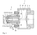
- Fig. 1 shows a drill head 1 of a deep hole drilling machine. From the basic Such a Tietlochbohrmaschine from DE is constructed 43 18 830 Cl known. so on a description of other components than the drill head I can be dispensed with.
- One in Fig. 1 only schematically dotted and interrupted drill 2 is in the deep hole drilling machine by means of a guide device 3 axially relative to one Housing 4 of the drill.
- the guide device 3 comprises a front guide device facing the material to be processed 5 for the drill 3 and a rear guide device, not shown.
- a material wall 6 of the material to be processed is indicated by dashed lines in FIG. 1.
- the tapping body 8 When drilling comes with the material wall 6 a contact wall 7 one annular tapping body 8 in contact.
- the tapping body 8 has one spherical zone-shaped outer wall, the first bearing wall 9 of a storage unit 10 for mounting the tapping body 8 in a base body 11 of the front guide device 5 is used.
- the first bearing wall 9 is flat on a complementary spherical zone-shaped second bearing wall 12 of the Basic body 11.
- the tapping body 8 is held in contact with the second bearing wall 12 Via a connecting body designed as a screw ring 13, which as Clamping body for the tapping body 8 is used.
- the screw ring 13 has a spherical zone-shaped third bearing wall 14, which the second bearing wall 12 continues.
- the two bearing walls 12, 14 abut each other in the Area of an equatorial plane of that specified by the bearing unit 10 Spherical shape.
- Via an internal thread 15 the screw ring 13 is with a complementary external threads 16 of the base body 11 are screwed thereto.
- the base body 11 has a central one for receiving the drill 2 Through opening 17, which steps towards the contact wall 7 extended. Included in this extension is a guide bush 18, in which the drill 2 is guided. With the inner wall of the guide bush 18 in alignment is a passage opening 19 of the tapping body 8 executed that a passage of the drill 2 through the tapping body 8 at all possible orientations of the tapping body 8 to the base body 11 the front guide device 5 is given.
- One of the passage opening 19 facing end portion of the guide bush 18 has a spherical zone fourth bearing wall 19a on which a fifth inner bearing wall of the tapping body 8 abuts.
- All bearing walls 9, 12, 14, 19a, 19b are parts of the bearing unit 10, by means of a pivoting of the tapping body 8 around the center of the ball predetermined by the bearing unit 10 spherical surface is possible.
- the tapping body 8 has one conically widening limiting recess 19c, which the fifth bearing wall 19b on that facing away from the passage opening 19 Page continues.
- an internal thread 20 is provided.
- fully screwed position is the screwed End of the grub screw 21 on the outer wall of the base body 11 near the connecting surface between the second bearing wall 12 and the third Bearing wall 14, that is close to the equatorial plane of the bearing unit 10.
- at the grub screw 21 cannot be screwed in up to the base body 11 Tapping body 8 around the center of the ball specified by the bearing unit 10 be pivoted.
- a quick-locking device designed in the manner of a bayonet lock 22 is the base body 11 on a connecting body 23 attached, the latter in turn in a support body 24 of the guide device 3 is fixed.
- the quick locking device 22 is used for easy replacement of the base body 11 the components carried by them.
- the support body 24 is a Flange connection 25 with a chip housing 26, which is part of the housing 4 of the drill is connected.
- a chip housing 26 opens the through opening 17 of the base body 11.
- Fig. 1 upwards the chip housing 26 is through a transparent plastic disc 27 covered.
- the drill head 1 is handled as follows: First, one for suitable drill 2 inserted into the drill head 1 for each drilling application.
- a guide bushing 18 is first made from a set of Guide bushes of the same outer shape selected, their inner diameter corresponds to the outside diameter of the drill 2 such that the drill 2 is guided in the guide bushing 18.
- the tapping body 8 After inserting the appropriate guide bushing 18 into the base body 11 is the tapping body 8 on the initially free end of the guide bush 18 placed, the first bearing wall 9 of the tapping body 8 with the second bearing wall 12 of the base body 11 and at the same time the fourth bearing wall 19a of the guide bush 18 with the fifth bearing wall 19b of the tapping body 8 comes into contact. Then the screw ring 13 screwed onto the base body 1 until the third bearing wall 14 of the screw ring 13 with the first bearing wall 9 of the tapping body 8 comes into contact.
- the drill head 1 with the grub screw not screwed in 21 positioned to the material wall 6 to be machined until the contact wall 7 lies flat against the material wall 6.
- the drilling process is started with the drill 2.
- the flat area the contact wall 7 on the material wall 6 ensures a good one Completion of the drill head 1 with the material wall 6, so that a leak is prevented by chips or lubricants.
- Through the tapping body 8 can also ensure additional guidance of the drill 2 his. Chips generated during drilling are not shown in a Longitudinal groove in the drill 2 away from the drilling point towards the chip housing 26 guided.
- the degree of filling of the chip housing 26 can be via the plastic disc 27 be checked visually.
- a relative orientation of the tapping body 8 to the base body 11 can be secured with the grub screw 21. For this, this is in screwed the screw ring 13 so that it is against the base body 11 exerts radial pressure. As a result, the second bearing wall 12 of the Base body 11 pressed against the first bearing wall 9 of the tapping body 8 and creates a frictional connection between these bearing walls 9, 12, so that a pivoting of the tapping body 8 in the bearing unit 10 prevents or is difficult.
Landscapes
- Engineering & Computer Science (AREA)
- Mechanical Engineering (AREA)
- Drilling And Boring (AREA)
- Perforating, Stamping-Out Or Severing By Means Other Than Cutting (AREA)
Abstract
Description
- Fig. 1
- einen Längsschnitt durch einen Gehäuseabschnitt einer Bohrmaschine mit einer Führungsvorrichtung zur axialen Führung eines Bohrers;
- Fig. 2
- eine Seitenansicht einer Führungseinrichtung der Führungsvorrichtung von Fig. 1;
- Fig. 3
- einen Längsschnitt durch die Führungseinrichtung von Fig. 2 gemäß Linie III-III in Fig. 4 und
- Fig. 4
- eine weitere Seitenansicht der Führungseinrichtung.
Claims (10)
- Bohrmaschine, insbesondere zur Tieflochbohrung,gekennzeichnet durchmit einem Bohrer (2),mit einem Gehäuse (4),mit einer Führungsvorrichtung (3) zur axialen Führung des Bohrers (2) mit einer dem zu bearbeitenden Material zugewandten Führungseinrichtung (5),einen mit dem zu bearbeitenden Material über eine Kontaktwand (7) in Kontakt bringbaren Anbohrkörper (8) mit einer von der Kontaktwand (7) begrenzten Durchtrittsöffnung (19) für den Bohrer (2),wobei der Anbohrkörper (8) am Gehäuse (4) und/oder an der Führungseinrichtung (5) über eine Lagereinheit (10) derart gelagert ist, dass die Kontaktwand (7) sich hinsichtlich ihrer Orientierung zu einer Materialwand (6) des zu bearbeitenden Materials ausrichten kann, wenn die Kontaktwand (7) in Anlage an die Materialwand (6) kommt.
- Bohrmaschine nach Anspruch 1, dadurch gekennzeichnet, dass die Lagereinheit (10) eine kugelzonenförmige erste Lagerwand (9) des Anbohrkörpers (8) aufweist, welche mit einer kugelzonenförmigen zweiten Lagerwand (12) der Führungseinrichtung (5) zusammenarbeitet.
- Bohrmaschine nach Anspruch 1 oder 2, dadurch gekennzeichnet, dass der Anbohrkörper (8) über einen an der Führungseinrichtung (5) festgelegten Verbindungskörper (13), insbesondere einen Klemmkörper, mit der Führungseinrichtung (5) verbunden ist.
- Bohrmaschine nach Anspruch 3, dadurch gekennzeichnet, dass der Verbindungskörper (13) eine kugelzonenförmige dritte Lagerwand (14) der Lagereinheit (10) umfasst.
- Bohrmaschine nach Anspruch 3 oder 4, dadurch gekennzeichnet, dass der Verbindungskörper (13) derart ausgeführt ist, dass über diesen der Anpressdruck der ersten (9) an der zweiten (12) Lagerwand einstellbar ist.
- Bohrmaschine nach einem der Ansprüche 1 bis 5, dadurch gekennzeichnet, dass die Führungseinrichtung (5) eine Führungsbuchse (18), in welcher der Bohrer (2) geführt ist, aufweist, wobei der Anbohrkörper (8) über die Lagereinheit (10) zusätzlich an der Führungsbuchse (18) gelagert ist.
- Bohrmaschine nach Anspruch 6, dadurch gekennzeichnet, dass die Lagereinheit (10) eine Lagerwand (19b) des Anbohrkörpers (8) aufweist, welche mit einer kugelzonenförmigen Lagerwand (19a) der Führungsbuchse (18) zusammenarbeitet.
- Bohrmaschine nach Anspruch 6 oder 7, dadurch gekennzeichnet, dass die Führungsbuchse ( 18) derart in der Führungseinrichtung (5) gehaltert ist. dass sie ausgewechselt werden kann.
- Bohrmaschine nach einem der Ansprüche 1 bis 8, dadurch gekennzeichnet, dass die Führungseinrichtung (5) mit dem Anbohrkörper (8) über eine Schnell-Verriegelungseinrichtung (22) mit dem Gehäuse (4) verbunden ist.
- Bohrmaschine nach einem der Ansprüche 1 bis 9, gekennzeichnet durch eine Sicherungseinrichtung (21), die derart ausgeführt ist, dass in einer Sicherungsstellung der Sicherungseinrichtung (21) ein Ausrichten der Kontaktwand (7) verhindert bzw. erschwert ist.
Applications Claiming Priority (2)
| Application Number | Priority Date | Filing Date | Title |
|---|---|---|---|
| DE10325066 | 2003-06-03 | ||
| DE10325066A DE10325066A1 (de) | 2003-06-03 | 2003-06-03 | Bohrmaschine, insbesondere zur Tieflochbohrung |
Publications (2)
| Publication Number | Publication Date |
|---|---|
| EP1484126A1 true EP1484126A1 (de) | 2004-12-08 |
| EP1484126B1 EP1484126B1 (de) | 2008-03-26 |
Family
ID=33154527
Family Applications (1)
| Application Number | Title | Priority Date | Filing Date |
|---|---|---|---|
| EP04012959A Expired - Lifetime EP1484126B1 (de) | 2003-06-03 | 2004-06-02 | Bohrmaschine, insbesondere zur Tieflochbohrung |
Country Status (3)
| Country | Link |
|---|---|
| EP (1) | EP1484126B1 (de) |
| AT (1) | ATE390231T1 (de) |
| DE (2) | DE10325066A1 (de) |
Cited By (6)
| Publication number | Priority date | Publication date | Assignee | Title |
|---|---|---|---|---|
| WO2011038724A3 (de) * | 2009-10-02 | 2011-07-21 | Ferroll Gmbh | Spanwerkzeug, insbesondere schälwerkzeug, aufbohrkopf, vollbohrkopf oder bohrkopf, sowie zerspanungsmaschine und verfahren |
| US8025467B2 (en) * | 2007-02-26 | 2011-09-27 | Airbus Operations, S.L. | Countersinking-carrier nozzle |
| US20110320031A1 (en) * | 2009-03-06 | 2011-12-29 | Thyssenkrupp System Engineering Gmbh | Machining device for machining a workpiece |
| CN102430780A (zh) * | 2011-10-31 | 2012-05-02 | 南通爱慕希机械有限公司 | 一种阻尼孔深孔加工治具 |
| CN101450394B (zh) * | 2007-11-30 | 2013-01-09 | 上海诺玛液压系统有限公司 | 用于电液伺服阀中衔铁上通孔的加工夹具 |
| CN104985224A (zh) * | 2015-08-09 | 2015-10-21 | 王建玲 | 卧式多工位多级深孔钻进机床 |
Families Citing this family (1)
| Publication number | Priority date | Publication date | Assignee | Title |
|---|---|---|---|---|
| DE102018132192A1 (de) * | 2018-12-13 | 2020-06-18 | Böllhoff Verbindungstechnik GmbH | Hohlzylinderförmiges Basiselement einer Verbindungseinheit |
Citations (3)
| Publication number | Priority date | Publication date | Assignee | Title |
|---|---|---|---|---|
| FR705225A (fr) * | 1930-11-07 | 1931-06-02 | Dispositif de guidage des mèches dans les trous des gabarits de perçage | |
| DE1140047B (de) * | 1959-09-17 | 1962-11-22 | Ernst Heinkel Flugzeugbau G M | Bohrplatte mit exzentrisch die Bohrbuchse tragender Drehscheibe |
| DE4318830C1 (de) * | 1993-06-07 | 1995-01-26 | Markus Buck | Wahlweise mit einem Bohrwerkzeug oder einem Fräswerkzeug ausrüstbare Tieflochbohrmaschine |
Family Cites Families (2)
| Publication number | Priority date | Publication date | Assignee | Title |
|---|---|---|---|---|
| DE328473C (de) * | 1918-08-27 | 1920-10-28 | Alexanderwerk A Von Der Nahmer | Abfuellhahn mit von einem Schwenkarm getragener Verschlusskappe |
| DE556098C (de) * | 1931-08-29 | 1932-08-08 | Europaeischer Verband Der Flas | Schervorrichtung zum Abtrennen eines Glasrestes unterhalb einer Saugform |
-
2003
- 2003-06-03 DE DE10325066A patent/DE10325066A1/de not_active Withdrawn
-
2004
- 2004-06-02 DE DE502004006634T patent/DE502004006634D1/de not_active Expired - Lifetime
- 2004-06-02 AT AT04012959T patent/ATE390231T1/de active
- 2004-06-02 EP EP04012959A patent/EP1484126B1/de not_active Expired - Lifetime
Patent Citations (3)
| Publication number | Priority date | Publication date | Assignee | Title |
|---|---|---|---|---|
| FR705225A (fr) * | 1930-11-07 | 1931-06-02 | Dispositif de guidage des mèches dans les trous des gabarits de perçage | |
| DE1140047B (de) * | 1959-09-17 | 1962-11-22 | Ernst Heinkel Flugzeugbau G M | Bohrplatte mit exzentrisch die Bohrbuchse tragender Drehscheibe |
| DE4318830C1 (de) * | 1993-06-07 | 1995-01-26 | Markus Buck | Wahlweise mit einem Bohrwerkzeug oder einem Fräswerkzeug ausrüstbare Tieflochbohrmaschine |
Cited By (6)
| Publication number | Priority date | Publication date | Assignee | Title |
|---|---|---|---|---|
| US8025467B2 (en) * | 2007-02-26 | 2011-09-27 | Airbus Operations, S.L. | Countersinking-carrier nozzle |
| CN101450394B (zh) * | 2007-11-30 | 2013-01-09 | 上海诺玛液压系统有限公司 | 用于电液伺服阀中衔铁上通孔的加工夹具 |
| US20110320031A1 (en) * | 2009-03-06 | 2011-12-29 | Thyssenkrupp System Engineering Gmbh | Machining device for machining a workpiece |
| WO2011038724A3 (de) * | 2009-10-02 | 2011-07-21 | Ferroll Gmbh | Spanwerkzeug, insbesondere schälwerkzeug, aufbohrkopf, vollbohrkopf oder bohrkopf, sowie zerspanungsmaschine und verfahren |
| CN102430780A (zh) * | 2011-10-31 | 2012-05-02 | 南通爱慕希机械有限公司 | 一种阻尼孔深孔加工治具 |
| CN104985224A (zh) * | 2015-08-09 | 2015-10-21 | 王建玲 | 卧式多工位多级深孔钻进机床 |
Also Published As
| Publication number | Publication date |
|---|---|
| DE10325066A1 (de) | 2004-12-23 |
| EP1484126B1 (de) | 2008-03-26 |
| ATE390231T1 (de) | 2008-04-15 |
| DE502004006634D1 (de) | 2008-05-08 |
Similar Documents
| Publication | Publication Date | Title |
|---|---|---|
| EP2950955B1 (de) | Werkzeugaufnahme für ein werkzeug mit einem mit einem aussengewinde versehenen werkzeugschaft | |
| DE3108439C1 (de) | Bohrwerkzeug, insbesondere Bohrstange | |
| DE60131780T2 (de) | Werkzeug und senker für spanabhebendes arbeiten | |
| DE69928548T2 (de) | Bohrwerkzeugzusammenbau | |
| DE29504857U1 (de) | Bohrlehre für chirurgische Bohrwerkzeuge | |
| EP2114599B1 (de) | Ausgewuchtetes ausbohrwerkzeug mit klemmeinrichtung | |
| EP0687516A1 (de) | Kombinationswerkzeug | |
| EP0141451A1 (de) | Werkzeugaufnahmevorrichtung und Werkzeugträger | |
| DE102009012155A1 (de) | Bearbeitungseinrichtung zur Bearbeitung eines Werkstücks | |
| DE69117286T2 (de) | Bohrer mit Senkgerät | |
| DE10315394A1 (de) | Ausbohrwerkzeug | |
| DE102017104914A1 (de) | Anschlag für ein Bohr-, Fräs- oder Senkwerkzeug | |
| DE1602750C3 (de) | Einrichtung zum Zuführen von Kühlmitteln in einem Spannfutter für Werkzeuge mit einem zylindrischen Werkzeugschaft | |
| CH654232A5 (de) | Bohrwerkzeug. | |
| DE10154434B4 (de) | Anschlagvorrichtung | |
| EP1484126B1 (de) | Bohrmaschine, insbesondere zur Tieflochbohrung | |
| DE102021110462A1 (de) | Rotationsschneidwerkzeug sowie Halteelement für ein Rotationsschneidwerkzeug | |
| EP3606693B1 (de) | Bohrwerkzeug mit wechselschneidplatte | |
| DE2852209C2 (de) | Senkwerkzeug | |
| DE8422976U1 (de) | Werkzeughalter mit Radialverstellvorrichtung für ein Werkzeug, insbesondere ein rotierendes Werkzeug | |
| DE10108103B9 (de) | Maschinenwerkzeug mit verstellbarer Schneidplatte | |
| DE3131478A1 (de) | Vorrichtung zur verbindung zweier um eine gemeinsame achse rotierender werkzeugteile | |
| DE3204245C2 (de) | Halter für ein Bohrwerkzeug | |
| EP3890910B1 (de) | Bohrkopf zum auskesseln von nicht-zylindrischen innenkonturen | |
| DE3307458A1 (de) | Tiefbohrwerkzeug und tiefbohrvorrichtung |
Legal Events
| Date | Code | Title | Description |
|---|---|---|---|
| PUAI | Public reference made under article 153(3) epc to a published international application that has entered the european phase |
Free format text: ORIGINAL CODE: 0009012 |
|
| AK | Designated contracting states |
Kind code of ref document: A1 Designated state(s): AT BE BG CH CY CZ DE DK EE ES FI FR GB GR HU IE IT LI LU MC NL PL PT RO SE SI SK TR |
|
| AX | Request for extension of the european patent |
Extension state: AL HR LT LV MK |
|
| 17P | Request for examination filed |
Effective date: 20050216 |
|
| AKX | Designation fees paid |
Designated state(s): AT BE BG CH CY CZ DE DK EE ES FI FR GB GR HU IE IT LI LU MC NL PL PT RO SE SI SK TR |
|
| GRAP | Despatch of communication of intention to grant a patent |
Free format text: ORIGINAL CODE: EPIDOSNIGR1 |
|
| GRAS | Grant fee paid |
Free format text: ORIGINAL CODE: EPIDOSNIGR3 |
|
| GRAA | (expected) grant |
Free format text: ORIGINAL CODE: 0009210 |
|
| AK | Designated contracting states |
Kind code of ref document: B1 Designated state(s): AT BE BG CH CY CZ DE DK EE ES FI FR GB GR HU IE IT LI LU MC NL PL PT RO SE SI SK TR |
|
| REG | Reference to a national code |
Ref country code: GB Ref legal event code: FG4D Free format text: NOT ENGLISH |
|
| REG | Reference to a national code |
Ref country code: CH Ref legal event code: EP Ref country code: IE Ref legal event code: FG4D Free format text: LANGUAGE OF EP DOCUMENT: GERMAN |
|
| REF | Corresponds to: |
Ref document number: 502004006634 Country of ref document: DE Date of ref document: 20080508 Kind code of ref document: P |
|
| PG25 | Lapsed in a contracting state [announced via postgrant information from national office to epo] |
Ref country code: FI Free format text: LAPSE BECAUSE OF FAILURE TO SUBMIT A TRANSLATION OF THE DESCRIPTION OR TO PAY THE FEE WITHIN THE PRESCRIBED TIME-LIMIT Effective date: 20080326 |
|
| NLV1 | Nl: lapsed or annulled due to failure to fulfill the requirements of art. 29p and 29m of the patents act | ||
| PG25 | Lapsed in a contracting state [announced via postgrant information from national office to epo] |
Ref country code: SI Free format text: LAPSE BECAUSE OF FAILURE TO SUBMIT A TRANSLATION OF THE DESCRIPTION OR TO PAY THE FEE WITHIN THE PRESCRIBED TIME-LIMIT Effective date: 20080326 Ref country code: PL Free format text: LAPSE BECAUSE OF FAILURE TO SUBMIT A TRANSLATION OF THE DESCRIPTION OR TO PAY THE FEE WITHIN THE PRESCRIBED TIME-LIMIT Effective date: 20080326 |
|
| REG | Reference to a national code |
Ref country code: IE Ref legal event code: FD4D |
|
| PG25 | Lapsed in a contracting state [announced via postgrant information from national office to epo] |
Ref country code: ES Free format text: LAPSE BECAUSE OF FAILURE TO SUBMIT A TRANSLATION OF THE DESCRIPTION OR TO PAY THE FEE WITHIN THE PRESCRIBED TIME-LIMIT Effective date: 20080707 Ref country code: SK Free format text: LAPSE BECAUSE OF FAILURE TO SUBMIT A TRANSLATION OF THE DESCRIPTION OR TO PAY THE FEE WITHIN THE PRESCRIBED TIME-LIMIT Effective date: 20080326 Ref country code: CZ Free format text: LAPSE BECAUSE OF FAILURE TO SUBMIT A TRANSLATION OF THE DESCRIPTION OR TO PAY THE FEE WITHIN THE PRESCRIBED TIME-LIMIT Effective date: 20080326 Ref country code: SE Free format text: LAPSE BECAUSE OF FAILURE TO SUBMIT A TRANSLATION OF THE DESCRIPTION OR TO PAY THE FEE WITHIN THE PRESCRIBED TIME-LIMIT Effective date: 20080626 Ref country code: PT Free format text: LAPSE BECAUSE OF FAILURE TO SUBMIT A TRANSLATION OF THE DESCRIPTION OR TO PAY THE FEE WITHIN THE PRESCRIBED TIME-LIMIT Effective date: 20080901 |
|
| PG25 | Lapsed in a contracting state [announced via postgrant information from national office to epo] |
Ref country code: RO Free format text: LAPSE BECAUSE OF FAILURE TO SUBMIT A TRANSLATION OF THE DESCRIPTION OR TO PAY THE FEE WITHIN THE PRESCRIBED TIME-LIMIT Effective date: 20080326 Ref country code: NL Free format text: LAPSE BECAUSE OF FAILURE TO SUBMIT A TRANSLATION OF THE DESCRIPTION OR TO PAY THE FEE WITHIN THE PRESCRIBED TIME-LIMIT Effective date: 20080326 |
|
| BERE | Be: lapsed |
Owner name: UCK, HELMUT Effective date: 20080630 |
|
| EN | Fr: translation not filed | ||
| PG25 | Lapsed in a contracting state [announced via postgrant information from national office to epo] |
Ref country code: MC Free format text: LAPSE BECAUSE OF NON-PAYMENT OF DUE FEES Effective date: 20080630 Ref country code: DK Free format text: LAPSE BECAUSE OF FAILURE TO SUBMIT A TRANSLATION OF THE DESCRIPTION OR TO PAY THE FEE WITHIN THE PRESCRIBED TIME-LIMIT Effective date: 20080326 Ref country code: IE Free format text: LAPSE BECAUSE OF FAILURE TO SUBMIT A TRANSLATION OF THE DESCRIPTION OR TO PAY THE FEE WITHIN THE PRESCRIBED TIME-LIMIT Effective date: 20080326 |
|
| PLBE | No opposition filed within time limit |
Free format text: ORIGINAL CODE: 0009261 |
|
| STAA | Information on the status of an ep patent application or granted ep patent |
Free format text: STATUS: NO OPPOSITION FILED WITHIN TIME LIMIT |
|
| GBPC | Gb: european patent ceased through non-payment of renewal fee |
Effective date: 20080626 |
|
| 26N | No opposition filed |
Effective date: 20081230 |
|
| PG25 | Lapsed in a contracting state [announced via postgrant information from national office to epo] |
Ref country code: BE Free format text: LAPSE BECAUSE OF NON-PAYMENT OF DUE FEES Effective date: 20080630 |
|
| PG25 | Lapsed in a contracting state [announced via postgrant information from national office to epo] |
Ref country code: EE Free format text: LAPSE BECAUSE OF FAILURE TO SUBMIT A TRANSLATION OF THE DESCRIPTION OR TO PAY THE FEE WITHIN THE PRESCRIBED TIME-LIMIT Effective date: 20080326 Ref country code: BG Free format text: LAPSE BECAUSE OF FAILURE TO SUBMIT A TRANSLATION OF THE DESCRIPTION OR TO PAY THE FEE WITHIN THE PRESCRIBED TIME-LIMIT Effective date: 20080626 Ref country code: FR Free format text: LAPSE BECAUSE OF FAILURE TO SUBMIT A TRANSLATION OF THE DESCRIPTION OR TO PAY THE FEE WITHIN THE PRESCRIBED TIME-LIMIT Effective date: 20090116 |
|
| PG25 | Lapsed in a contracting state [announced via postgrant information from national office to epo] |
Ref country code: GB Free format text: LAPSE BECAUSE OF NON-PAYMENT OF DUE FEES Effective date: 20080626 |
|
| PG25 | Lapsed in a contracting state [announced via postgrant information from national office to epo] |
Ref country code: CY Free format text: LAPSE BECAUSE OF FAILURE TO SUBMIT A TRANSLATION OF THE DESCRIPTION OR TO PAY THE FEE WITHIN THE PRESCRIBED TIME-LIMIT Effective date: 20080326 |
|
| PG25 | Lapsed in a contracting state [announced via postgrant information from national office to epo] |
Ref country code: HU Free format text: LAPSE BECAUSE OF FAILURE TO SUBMIT A TRANSLATION OF THE DESCRIPTION OR TO PAY THE FEE WITHIN THE PRESCRIBED TIME-LIMIT Effective date: 20080927 Ref country code: LU Free format text: LAPSE BECAUSE OF NON-PAYMENT OF DUE FEES Effective date: 20080602 |
|
| PG25 | Lapsed in a contracting state [announced via postgrant information from national office to epo] |
Ref country code: TR Free format text: LAPSE BECAUSE OF FAILURE TO SUBMIT A TRANSLATION OF THE DESCRIPTION OR TO PAY THE FEE WITHIN THE PRESCRIBED TIME-LIMIT Effective date: 20080326 |
|
| PG25 | Lapsed in a contracting state [announced via postgrant information from national office to epo] |
Ref country code: GR Free format text: LAPSE BECAUSE OF FAILURE TO SUBMIT A TRANSLATION OF THE DESCRIPTION OR TO PAY THE FEE WITHIN THE PRESCRIBED TIME-LIMIT Effective date: 20080627 |
|
| PGFP | Annual fee paid to national office [announced via postgrant information from national office to epo] |
Ref country code: CH Payment date: 20120523 Year of fee payment: 9 |
|
| PGFP | Annual fee paid to national office [announced via postgrant information from national office to epo] |
Ref country code: IT Payment date: 20120623 Year of fee payment: 9 |
|
| PGFP | Annual fee paid to national office [announced via postgrant information from national office to epo] |
Ref country code: AT Payment date: 20120522 Year of fee payment: 9 |
|
| REG | Reference to a national code |
Ref country code: CH Ref legal event code: PL |
|
| REG | Reference to a national code |
Ref country code: AT Ref legal event code: MM01 Ref document number: 390231 Country of ref document: AT Kind code of ref document: T Effective date: 20130602 |
|
| PG25 | Lapsed in a contracting state [announced via postgrant information from national office to epo] |
Ref country code: LI Free format text: LAPSE BECAUSE OF NON-PAYMENT OF DUE FEES Effective date: 20130630 Ref country code: CH Free format text: LAPSE BECAUSE OF NON-PAYMENT OF DUE FEES Effective date: 20130630 |
|
| PG25 | Lapsed in a contracting state [announced via postgrant information from national office to epo] |
Ref country code: IT Free format text: LAPSE BECAUSE OF NON-PAYMENT OF DUE FEES Effective date: 20130602 Ref country code: AT Free format text: LAPSE BECAUSE OF NON-PAYMENT OF DUE FEES Effective date: 20130602 |
|
| PGFP | Annual fee paid to national office [announced via postgrant information from national office to epo] |
Ref country code: DE Payment date: 20140821 Year of fee payment: 11 |
|
| REG | Reference to a national code |
Ref country code: DE Ref legal event code: R119 Ref document number: 502004006634 Country of ref document: DE |
|
| PG25 | Lapsed in a contracting state [announced via postgrant information from national office to epo] |
Ref country code: DE Free format text: LAPSE BECAUSE OF NON-PAYMENT OF DUE FEES Effective date: 20160101 |