EP1484097B1 - Méthode pour la détermination des conditions d'épuisement d'une cartouche de filtration de carafe filtrante avec cartouche remplaçable et carafe filtrante fonctionnant selon cette méthode. - Google Patents
Méthode pour la détermination des conditions d'épuisement d'une cartouche de filtration de carafe filtrante avec cartouche remplaçable et carafe filtrante fonctionnant selon cette méthode. Download PDFInfo
- Publication number
- EP1484097B1 EP1484097B1 EP04008513A EP04008513A EP1484097B1 EP 1484097 B1 EP1484097 B1 EP 1484097B1 EP 04008513 A EP04008513 A EP 04008513A EP 04008513 A EP04008513 A EP 04008513A EP 1484097 B1 EP1484097 B1 EP 1484097B1
- Authority
- EP
- European Patent Office
- Prior art keywords
- filtering
- water
- cartridge
- carafe
- basin
- Prior art date
- Legal status (The legal status is an assumption and is not a legal conclusion. Google has not performed a legal analysis and makes no representation as to the accuracy of the status listed.)
- Expired - Lifetime
Links
- 238000001914 filtration Methods 0.000 title claims abstract description 50
- 238000000034 method Methods 0.000 title claims abstract description 16
- XLYOFNOQVPJJNP-UHFFFAOYSA-N water Substances O XLYOFNOQVPJJNP-UHFFFAOYSA-N 0.000 claims abstract description 46
- 230000004913 activation Effects 0.000 claims description 8
- 238000007654 immersion Methods 0.000 claims description 2
- 238000005259 measurement Methods 0.000 claims 1
- 230000000875 corresponding effect Effects 0.000 description 4
- 239000003344 environmental pollutant Substances 0.000 description 2
- 231100000719 pollutant Toxicity 0.000 description 2
- 238000010276 construction Methods 0.000 description 1
- 230000002596 correlated effect Effects 0.000 description 1
- 150000002500 ions Chemical class 0.000 description 1
- 239000000463 material Substances 0.000 description 1
- 230000010355 oscillation Effects 0.000 description 1
- 230000005236 sound signal Effects 0.000 description 1
- 230000000007 visual effect Effects 0.000 description 1
Images


Classifications
-
- C—CHEMISTRY; METALLURGY
- C02—TREATMENT OF WATER, WASTE WATER, SEWAGE, OR SLUDGE
- C02F—TREATMENT OF WATER, WASTE WATER, SEWAGE, OR SLUDGE
- C02F1/00—Treatment of water, waste water, or sewage
- C02F1/001—Processes for the treatment of water whereby the filtration technique is of importance
- C02F1/003—Processes for the treatment of water whereby the filtration technique is of importance using household-type filters for producing potable water, e.g. pitchers, bottles, faucet mounted devices
-
- B—PERFORMING OPERATIONS; TRANSPORTING
- B01—PHYSICAL OR CHEMICAL PROCESSES OR APPARATUS IN GENERAL
- B01D—SEPARATION
- B01D35/00—Filtering devices having features not specifically covered by groups B01D24/00 - B01D33/00, or for applications not specifically covered by groups B01D24/00 - B01D33/00; Auxiliary devices for filtration; Filter housing constructions
- B01D35/14—Safety devices specially adapted for filtration; Devices for indicating clogging
- B01D35/143—Filter condition indicators
-
- C—CHEMISTRY; METALLURGY
- C02—TREATMENT OF WATER, WASTE WATER, SEWAGE, OR SLUDGE
- C02F—TREATMENT OF WATER, WASTE WATER, SEWAGE, OR SLUDGE
- C02F2209/00—Controlling or monitoring parameters in water treatment
- C02F2209/02—Temperature
-
- C—CHEMISTRY; METALLURGY
- C02—TREATMENT OF WATER, WASTE WATER, SEWAGE, OR SLUDGE
- C02F—TREATMENT OF WATER, WASTE WATER, SEWAGE, OR SLUDGE
- C02F2209/00—Controlling or monitoring parameters in water treatment
- C02F2209/05—Conductivity or salinity
-
- C—CHEMISTRY; METALLURGY
- C02—TREATMENT OF WATER, WASTE WATER, SEWAGE, OR SLUDGE
- C02F—TREATMENT OF WATER, WASTE WATER, SEWAGE, OR SLUDGE
- C02F2209/00—Controlling or monitoring parameters in water treatment
- C02F2209/44—Time
-
- C—CHEMISTRY; METALLURGY
- C02—TREATMENT OF WATER, WASTE WATER, SEWAGE, OR SLUDGE
- C02F—TREATMENT OF WATER, WASTE WATER, SEWAGE, OR SLUDGE
- C02F2209/00—Controlling or monitoring parameters in water treatment
- C02F2209/44—Time
- C02F2209/445—Filter life
-
- C—CHEMISTRY; METALLURGY
- C02—TREATMENT OF WATER, WASTE WATER, SEWAGE, OR SLUDGE
- C02F—TREATMENT OF WATER, WASTE WATER, SEWAGE, OR SLUDGE
- C02F2307/00—Location of water treatment or water treatment device
- C02F2307/04—Location of water treatment or water treatment device as part of a pitcher or jug
Definitions
- the object of the present invention is a method to determine the conditions of exhaustion of a filtering cartridge for filtering carafes with replaceable cartridge and a carafe operating in compliance with such method.
- Filtering carafes including a system of determination of the conditions of exhaustion of a filtering cartridge are familiar, for example by US 5,900,138 of the same applicant.
- the filtering power of the cartridge does not vary according to the quantity of water treated but also according to its quality.
- the filtering carafes available up until today include a counting system of the filtering cycles carried out from initial activation of the cartridge, identified for example according to the counting of the number of accesses to the first water collection basin to be filtered.
- a counting system of the filtering cycles carried out from initial activation of the cartridge identified for example according to the counting of the number of accesses to the first water collection basin to be filtered.
- an auxiliary counting system which counts the amount of time from the initial activation of the cartridge, compared with a time limit of lifespan of the cartridge, in order to calculate the exhaustion of the cartridge according to the first of the two events (exhaustion of time from the first activation - counting of the filtered water) that is verified.
- Carafes capable of calculating the exhaustion of the cartridge according to the quality of the water treated are not currently known.
- a main objective of the invention is to provide a method of determination of the conditions of exhaustion of a filter cartridge for filtering carafes with replaceable cartridge in which the condition of exhaustion is established in an accurate and reliable manner.
- Another objective of the invention is to provide a filtering carafe with replaceable cartridge operating in compliance with such method and at the same time built in a simple and functional way.
- Another objective of the findings is to provide a carafe that, in one single device, incorporates all of the indicators desired for an accurate determination of the conditions of exhaustion of the cartridge.
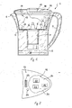
- drawing 1 indicates on the whole a filtering carafe including a container 2 with a handle 3 and an opposite pouring spout 4.
- Container 2 holds a removable feedbox 5 in which the first basin 6 is defined, destined for collection of water to be filtered, the bottom of which has an open discharge conduit 7 destined to hold a filtering cartridge 8 of a replaceable kind.
- Container 2 also holds a second basin 10 for collection of the filtered water.
- Container 2 is closed by a removable cover 11 which may be fitted with an open top 12 (drawings 3 and 4) in order to fill the first basin 6.
- the water treatment process is carried out by introducing the water to be filtered into the first basin, prior to removal of the cover 11 that is to say prior to opening of the door 12 so that the water flows through the conduit 7 through the filter bed that is located in the cartridge 8 and passes onto the second basin.
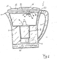
- the first basin includes an impedance measurer of the water to be filtered operatively connected to calculation means of the conditions of exhaustion of the cartridge.
- the impedance measurer is generally indicated by 15 and the calculations means are generally indicated by 16.
- the impedance measurer includes at least two electrodes 17, 18 which are fitted in the first basin 6 and between which an electric circuit can be closed in the presence of water to be filtered. It is preferable that measuring is carried out in direct current, generated by a small accumulator 19, and therefore the impedance measured is equal to the electrical resistance of the water to be filtered. As well as measuring the conductivity of the water to be filtered, the value of which is correlated to the concentration of ions and as such affects the lifespan of the filtering cartridge 8, the electrodes 17, 18 are also used as counting means to identify the number of times the first collection basin is filled and the consequent amount of water already filtered. In order to do so it is preferable that measures are made to prevent that simple shaking of the carafe 1 may lead to the creation of a counting signal following temporary immersion of the two electrodes and subsequent closing of the electrical circuit between them.
- An initial trick lies in the position of the electrode 17 close to the bottom of the first basin 6 while the electrode 18 is placed close to the cover 11. Furthermore, in addition to the two measuring electrodes 17, 18 two consent electrodes 21 are also provided, with the task of identifying contemporarily with the measuring electrodes the state of submersion in the water to be filtered and therefore to confirm that the submersion of the electrodes 17, 18 has not been accidentally provoked by movement of the carafe.
- Electrodes 17, 18 are fitted onto the cover and extended in a filling conduit 32 which flows into the basin 6 at the opening point 33.
- the electrodes 17, 18 are preferably contained, at least partially, in a chamber 34 the bottom of which contains passages 35 suitably created in terms of dimension in order to time the emptying of the chamber 34 compared with a minimum predefined period of time. This avoids that simple temporary accidental submersions of the electrodes due to movements of the carafe may generate false calculations.
- the result is achieved by defining a minimum period of time of submersion of the electrodes which exceeds a time limit established so that the signal generated is received as effective by the counting means 16.
- a limit may be defined for means of calculation in such a way that only closing signals of the circuit that exceed or are equal to a period of 40 seconds are considered. Signals that last less than 40 seconds will be ignored.
- the electrodes 17, 18, 21 derive from a circuit 20 powered by the accumulator 19 and includes counting means 22 to count the filling cycles of the said first basin and furthermore includes a display 23 susceptible to highlight important information of the filtering cycles carried out and/or the residual lifespan of the cartridge 8.
- the circuit 20 includes timers 24 to measure the amount of time that has passed from initial use of the cartridge and to calculate the amount of time left until its exhaustion and signal means 25, such as a visual LED alarm and/or a buzzer or other kind of sound signal, to inform the user of exhaustion of the filtering cartridge.
- signal means 25 such as a visual LED alarm and/or a buzzer or other kind of sound signal
- the means 17, 18, 21 identify closing of the circuit 20 during each new filling of the first basin 6 and at the same time false indications of closing of the circuit 20 following accidental submersion of the electrodes 17, 18, 21 are avoided.
- circuit 20 includes a timer 26 activated upon each closing of the circuit 20 in order to exclude counting if the duration of the afore-mentioned closing extends for an amount of time lower than the limit value predefined.
- the timer 26 therefore acts as a signal excluder device susceptible to accepting identification only if it extends beyond the predefined time limit.
- the erection of a pair of watertight panels aimed at creating a labyrinth passage to prevent accidental closing of the circuit in the absence of effective filling of the first basin 6 is also provided for between the measuring electrodes 17, 18.
- the signals measured by the electrodes 17, 18, 21, the counting means 22 and the timers 24, 26 are fed to an input of a microprocessor 30 that, on the basis of a resident programme, elaborates important data on the lifespan of the cartridge according to the amount of time passed since its first activation and the amount of water treated, identified in terms of closure considered important by the circuit between the electrodes, and by the ionic concentration of the pollutants, identified in terms of conductivity of the water being treated.
- the important data calculated in this way is visualised, preferably in terms of a "count-down", on the display 23 which indicates the number of cycles remaining until exhaustion of the cartridge 8.
- FIG. 5 illustrates another example of this present invention. Similar details are marked using the same numerical references as the previous Drawings.
- Drawing 5 is rather useful to take into consideration, in the calculation of exhaustion of the cartridge 8, of partial fillings of the first collection basin 6.
- a watertight panel 52 carries, close to the bottom, a gauged opening 53 with the objective of minimizing level variations in the compensation chamber following oscillations of the carafe typically when it is inclined for pouring.
- the electrodes of level 51 are associated with a reference electrode 50, also located at the bottom of the compensation chamber.
- the electrodes 50, 51 are associated with corresponding branches of the measuring circuit of impedance so as to close the corresponding branch once the corresponding level of water in the basin is reached.
- reading of the impedance measurer provides an important value of the ratio between the quality of the water to be filtered and of the water filtered. Said value is therefore a direct index of the residual efficiency of the cartridge when measuring is carried out and highlights the capacity of the cartridge to carry out other filters or the need for replacement.
- Said sensor may alternatively be placed in the lower basin 10, as long as the temperature of the water to be filtered is not subject to appreciable variations.
- the temperature measured is sent to the calculation means 16 and is used to correct the calculation of the conditions of exhaustion of the cartridge according to the temperature measured. In fact as the temperature increases a corresponding increase in electric conductivity measure due to a variation in the ionic concentration entirely in the solution is expected.
Claims (24)
- Procédé de détermination des conditions d'épuisement d'une cartouche de filtration pour des carafes filtrantes (1) avec une cartouche remplaçable (8), dans lequel est prévue une détermination initiale d'impédance d'eau à filtrer pour calculer ensuite un paramètre important pour la détermination de la durée de vie efficace de la cartouche de filtration (8).
- Procédé selon la revendication 1, dans lequel ladite détermination d'impédance est effectuée dans l'eau filtrée.
- Procédé selon la revendication 1 ou 2, dans lequel au moins une seconde détermination est choisie entre l'identification de la quantité d'eau traitée et l'identification de la quantité de temps depuis la première utilisation de la cartouche.
- Procédé selon la revendication 1 ou 3, dans lequel au moins l'une desdites première et seconde identifications est effectuée en utilisant des électrodes (17, 18) pouvant être immergées dans un premier réservoir (6) d'eau à filtrer.
- Procédé selon l'une ou plusieurs des revendications précédentes, dans lequel l'identification d'impédance est effectuée en courant continu identifiant une mesure de conductivité électrique de l'eau à traiter.
- Procédé selon l'une ou plusieurs des revendications précédentes, dans lequel est prévue une identification de la température de l'eau filtrée pour corriger ledit paramètre important conformément à une identification de température.
- Procédé selon l'une ou plusieurs des revendications précédentes, dans lequel ladite identification d'impédance est effectuée dans l'eau filtrée et dans l'eau à filtrer, ledit paramètre important pour la détermination de la durée de vie de la cartouche filtrante étant calculé conformément auxdites deux valeurs d'impédance.
- Carafe filtrante (1) avec cartouche remplaçable (8) comprenant un premier réservoir (6) d'eau à filtrer, un conduit d'écoulement (7) provenant dudit premier réservoir (6) et une cartouche filtrante (8) placée sur ledit conduit d'écoulement (7) pour dépurer l'eau se déplaçant du premier réservoir (6) vers un second réservoir (10) pour le stockage de l'eau filtrée, caractérisée par le fait qu'elle comprend, dans ledit premier réservoir (6), un circuit de mesure d'impédance de l'eau à filtrer relié en fonctionnement à des moyens de calcul des conditions d'épuisement de la cartouche.
- Carafe filtrante (1) selon la revendication 8, dans laquelle ledit mesureur d'impédance comprend au moins deux électrodes (17, 18) dans ledit premier réservoir (6) entre lesquelles un circuit électrique (20) est fermé en présence d'eau dans ledit premier réservoir (6).
- Carafe filtrante (1) selon la revendication 8 ou 9, dans laquelle ledit circuit (20) comprend des moyens de comptage (22) pour compter les cycles de remplissage dudit premier réservoir (6).
- Carafe filtrante (1) selon la revendication 8, 9 ou 10, dans laquelle lesdites électrodes (17, 18) sont appliquées audit couvercle (11).
- Carafe filtrante (1) selon la revendication 11, dans laquelle lesdites électrodes (17, 18) sont appliquées à un conduit de remplissage (32) du premier réservoir (6).
- Carafe filtrante (1) selon la revendication 12, dans laquelle lesdites électrodes (17, 18) sont appliquées en correspondance avec une chambre (34) dudit conduit pouvant se vider en une période de temps prédéfinie minimum.
- Carafe filtrante (1) selon la revendication 13, dans laquelle ladite chambre (34) comprend des passages calibrés (35).
- Carafe filtrante (1) selon l'une ou plusieurs des revendications 8 à 14, dans laquelle ledit circuit (20) comprend des horloges (24) pour mesurer la quantité de temps à partir de la première utilisation de la cartouche (8) et pour calculer la quantité de temps restant jusqu'à son épuisement.
- Carafe filtrante (1) selon la revendication 15, dans laquelle lesdites horloges (24) sont soumises auxdites électrodes (17, 18).
- Carafe filtrante (1) selon l'une ou plusieurs des revendications 8 à 16, dans laquelle ledit circuit (20) comprend des moyens de signal (23) pour indiquer l'épuisement de la cartouche de filtration (8).
- Carafe filtrante (1) selon l'une ou plusieurs des revendications 8 à 17, comprenant des moyens d'identification (17, 18, 21) pour identifier la fermeture du circuit chaque fois que le premier réservoir (6) est rempli et simultanément pour exclure l'identification de la fermeture du circuit (20) dans le cas d'une submersion lesdites électrodes (17, 18).
- Carafe filtrante (1) selon la revendication 18, dans laquelle lesdits moyens d'identification (17, 18, 19) comprennent un dispositif d'exclusion de signal (26) pouvant accepter l'identification seulement si la limite de temps prédéfinie est dépassée.
- Carafe filtrante (1) selon l'une ou plusieurs des revendications 8 à 19, dans laquelle lesdits moyens d'identification comprennent des électrodes d'homologation (21) situées dans ledit réservoir.
- Cartouche filtrante (1) selon l'une ou plusieurs des revendications 8 à 20, dans laquelle ledit circuit électrique (20) comporte un circuit à courant continu pouvant identifier la conductivité électrique de l'eau à traiter.
- Carafe filtrante (1) selon l'une ou plusieurs des revendications 8 à 21, dans laquelle ledit circuit de mesure d'impédance est associé à l'un et/ou l'autre desdits réservoirs.
- Carafe filtrante (1) selon l'une ou plusieurs des revendications 9 à 22, comprenant une pluralité d'électrodes (51, 50, 51', 50') situées dans l'un et/ou l'autre réservoir (6, 10) à des niveaux augmentant progressivement correspondant à des subdivisions du circuit de mesure d'impédance associé auxdites électrodes de manière à fermer le circuit dans la subdivision correspondante une fois que le niveau correspondant d'eau dans le réservoir respectif (6, 10) a été atteint.
- Carafe filtrante (1) selon la revendication 23, dans laquelle lesdites subdivisions du circuit de mesure sont associées aux moyens de calcul pour ajouter la quantité d'eau traitée pendant une durée de vie efficace de la cartouche (8) et pour établir ensuite les conditions d'épuisement.
Priority Applications (7)
| Application Number | Priority Date | Filing Date | Title |
|---|---|---|---|
| PL04008513T PL1484097T3 (pl) | 2003-06-04 | 2004-04-08 | Sposób określania stanów zużycia wkładu filtrującego do dzbanków z wymiennym wkładem i dzbanek działający zgodnie z takim sposobem |
| SI200430152T SI1484097T1 (sl) | 2003-06-04 | 2004-04-08 | Postopek za dolocanje stanja izcrpanosti filtrirne patrone za lovilno rocko z izmenljivo patrono in lovilna rocka za obratovanje ob upostevanju tega postopka |
| CA2475198A CA2475198C (fr) | 2004-04-08 | 2004-07-20 | Methode de determination des conditions d'epuisement d'une cartouche filtrante pour carafes filtrantes a cartouche remplacable et une carafe fonctionnant selon cette methode |
| US10/895,319 US7294277B2 (en) | 2004-04-08 | 2004-07-21 | Method of determination of the conditions of exhaustion of a filtering cartridge for filtering carafes with replaceable cartridge and carafe operating in compliance with such method |
| JP2004228589A JP5030125B2 (ja) | 2004-04-08 | 2004-08-04 | 交換可能なカートリッジを備えた濾過カラフのためのフィルタカートリッジの消耗の状態を測定する方法および上述の方法に応じて作動するカラフ |
| CN200410087033A CN100574842C (zh) | 2004-04-08 | 2004-10-22 | 确定滤壶的可更换滤筒耗竭状况的方法及依此法操作的壶 |
| US11/859,730 US7678282B2 (en) | 2004-04-08 | 2007-09-21 | Method of determination of the conditions of exhaustion of a filtering cartridge for filtering carafes with replaceable cartridge and carafe operating in compliance with such method |
Applications Claiming Priority (2)
| Application Number | Priority Date | Filing Date | Title |
|---|---|---|---|
| ITPD20030121 | 2003-06-04 | ||
| IT000121A ITPD20030121A1 (it) | 2003-06-04 | 2003-06-04 | Metodo di determinazione delle condizioni di esaurimento di |
Publications (2)
| Publication Number | Publication Date |
|---|---|
| EP1484097A1 EP1484097A1 (fr) | 2004-12-08 |
| EP1484097B1 true EP1484097B1 (fr) | 2006-10-11 |
Family
ID=33156357
Family Applications (1)
| Application Number | Title | Priority Date | Filing Date |
|---|---|---|---|
| EP04008513A Expired - Lifetime EP1484097B1 (fr) | 2003-06-04 | 2004-04-08 | Méthode pour la détermination des conditions d'épuisement d'une cartouche de filtration de carafe filtrante avec cartouche remplaçable et carafe filtrante fonctionnant selon cette méthode. |
Country Status (7)
| Country | Link |
|---|---|
| EP (1) | EP1484097B1 (fr) |
| AT (1) | ATE342114T1 (fr) |
| DE (1) | DE602004002728T2 (fr) |
| ES (1) | ES2273114T3 (fr) |
| IT (1) | ITPD20030121A1 (fr) |
| PL (1) | PL1484097T3 (fr) |
| SI (1) | SI1484097T1 (fr) |
Cited By (1)
| Publication number | Priority date | Publication date | Assignee | Title |
|---|---|---|---|---|
| CN101827789A (zh) * | 2007-07-31 | 2010-09-08 | 塞尔温社团有限公司 | 带有可更换滤芯的渗滤式过滤系统、用于确定过滤系统中的可更换滤芯的效能耗尽的方法以及结合这种方法的成套装置 |
Families Citing this family (17)
| Publication number | Priority date | Publication date | Assignee | Title |
|---|---|---|---|---|
| DE102004011066A1 (de) * | 2004-03-06 | 2005-09-22 | Aqua Select Gmbh | Vorrichtung zur Reingiung von Wasser |
| ITTO20040903A1 (it) * | 2004-12-24 | 2005-03-24 | Eltek Spa | Dispositivo per la rilevazione di caratteristiche di un fluido in autoveicoli |
| DE102005035045B9 (de) | 2005-07-27 | 2007-11-08 | Brita Gmbh | Messvorrichtung für die Bestimmung von Durchflussmengen elektrisch leitender Flüssigkeiten, Messelement und Verfahren |
| EP1752421A1 (fr) * | 2005-08-12 | 2007-02-14 | Aquis Wasser-Luft-Systeme GmbH, Lindau | Dispositif pour le traitement de l'eau |
| EP1806322A1 (fr) * | 2006-01-07 | 2007-07-11 | Wal SA | Dispositif de filtration d'eau avec cartouche filtrante remplaçable |
| DE102006006230B3 (de) * | 2006-02-09 | 2007-11-15 | Anna Distribution Lp | Wechselanzeige für eine Wasserfiltervorrichtung |
| RU2446859C2 (ru) * | 2007-07-31 | 2012-04-10 | Селвин Корпорейт Лтд. | Перколяционная фильтрующая система со сменным картриджем, способ определения истощения сменного картриджа в фильтрующей системе и комплект, интегрирующий этот способ |
| ES2387188T3 (es) | 2008-03-28 | 2012-09-17 | Brita Gmbh | Método para medir el volumen de caudal de líquidos eléctricamente conductores a través de una vasija |
| DE102008023488C5 (de) | 2008-05-14 | 2021-12-09 | Bwt Water+More Gmbh | Wasserfiltervorrichtung |
| IT1394870B1 (it) * | 2009-06-10 | 2012-07-20 | Laica Spa | Sistema filtrante |
| DE102010061953A1 (de) * | 2010-11-25 | 2012-05-31 | Delphin Water Systems Gmbh & Co. Kg | Vorrichtung zur Entfernung von Verunreinigungen aus einer Flüssigkeit |
| RU2460972C1 (ru) * | 2011-04-22 | 2012-09-10 | Закрытое акционерное общество "МЕТТЭМ-технологии" | Способ определения количества электропроводящей жидкости и комплекс оборудования для его реализации |
| ITMI20112299A1 (it) | 2011-12-18 | 2013-06-19 | Tenacta Group Spa | Dispositivo filtrante per filtrare liquidi |
| RU2527854C2 (ru) * | 2012-11-30 | 2014-09-10 | Государственное бюджетное образовательное учреждение высшего прфессионального образования "Кировская государственная медицинская академия" Министерства здравоохранения Российской Федерации (ГБОУ ВПО Кировская ГМА Минздрава России) | Способ в.г. вохмянина определения окончания срока годности картриджей автономных устройств для обработки подаваемой самотеком воды (варианты). |
| EP2960210A1 (fr) | 2014-06-26 | 2015-12-30 | Electrolux Appliances Aktiebolag | Broc muni d'un indicateur capable de détecter la condition du filtre associé |
| RU2669276C1 (ru) * | 2016-07-08 | 2018-10-09 | Акционерное Общество "БВТ БАРЬЕР РУС" | Способ определения количества жидкости, вытекающей из ёмкости произвольной формы |
| JP2024502663A (ja) * | 2021-01-15 | 2024-01-22 | ブリタ エスエー | ろ過装置 |
Family Cites Families (6)
| Publication number | Priority date | Publication date | Assignee | Title |
|---|---|---|---|---|
| US5131277A (en) * | 1990-01-16 | 1992-07-21 | Teledyne Industries, Inc. | Reverse osmosis system |
| JP3327636B2 (ja) * | 1992-09-14 | 2002-09-24 | 勝夫 江原 | 寿命インジケーター及びカートリッジ |
| EP0788397B1 (fr) * | 1994-10-28 | 2000-12-27 | LAICA S.r.L. | Recipient pour la filtration de liquides et notamment de l'eau potable |
| DE19731092A1 (de) * | 1997-07-19 | 1999-01-21 | Brita Wasserfilter | Einrichtung für die Anzeige der Erschöpfung eines Reinigungsmittels |
| DE19819098A1 (de) * | 1998-04-29 | 1999-11-11 | Brita Gmbh | Wasserreinigungsvorrichtung mit Mitteln zur Anzeige der Erschöpfung des Reinigungsmittels |
| AU2001263691A1 (en) * | 2000-06-05 | 2001-12-17 | Hb Innovation Ltd. | Fluid flow meter system |
-
2003
- 2003-06-04 IT IT000121A patent/ITPD20030121A1/it unknown
-
2004
- 2004-04-08 AT AT04008513T patent/ATE342114T1/de active
- 2004-04-08 ES ES04008513T patent/ES2273114T3/es not_active Expired - Lifetime
- 2004-04-08 PL PL04008513T patent/PL1484097T3/pl unknown
- 2004-04-08 SI SI200430152T patent/SI1484097T1/sl unknown
- 2004-04-08 DE DE602004002728T patent/DE602004002728T2/de not_active Expired - Lifetime
- 2004-04-08 EP EP04008513A patent/EP1484097B1/fr not_active Expired - Lifetime
Cited By (1)
| Publication number | Priority date | Publication date | Assignee | Title |
|---|---|---|---|---|
| CN101827789A (zh) * | 2007-07-31 | 2010-09-08 | 塞尔温社团有限公司 | 带有可更换滤芯的渗滤式过滤系统、用于确定过滤系统中的可更换滤芯的效能耗尽的方法以及结合这种方法的成套装置 |
Also Published As
| Publication number | Publication date |
|---|---|
| ATE342114T1 (de) | 2006-11-15 |
| SI1484097T1 (sl) | 2007-04-30 |
| EP1484097A1 (fr) | 2004-12-08 |
| ES2273114T3 (es) | 2007-05-01 |
| PL1484097T3 (pl) | 2007-03-30 |
| DE602004002728T2 (de) | 2007-08-16 |
| ITPD20030121A1 (it) | 2004-12-05 |
| DE602004002728D1 (de) | 2006-11-23 |
Similar Documents
| Publication | Publication Date | Title |
|---|---|---|
| US7678282B2 (en) | Method of determination of the conditions of exhaustion of a filtering cartridge for filtering carafes with replaceable cartridge and carafe operating in compliance with such method | |
| EP1484097B1 (fr) | Méthode pour la détermination des conditions d'épuisement d'une cartouche de filtration de carafe filtrante avec cartouche remplaçable et carafe filtrante fonctionnant selon cette méthode. | |
| JP5559141B2 (ja) | 容器を通る導電性流体の体積流量測定方法 | |
| JP5038598B2 (ja) | 水の消費およびフィルター使用度をモニターするための装置 | |
| CN100563780C (zh) | 监视水消耗量和过滤器使用的装置和方法 | |
| EP2240252A1 (fr) | Procédé de détermination de l'épuisement d'une cartouche filtrante dans un système de filtration à cartouche remplaçable et dispositif fonctionnant conformément à ce procédé | |
| JP5384497B2 (ja) | 着脱可能なカートリッジを備えた濾過システムと、濾過システムの着脱可能なカートリッジの消耗を決定する方法と、この方法を果たすためのキット | |
| US20060011523A1 (en) | Water filter cartridge comprising an exchangeable testing unit that contains a conductance sensor | |
| EP2081475B1 (fr) | Carafe pour filtrer des liquides | |
| EP2440494B1 (fr) | Système de filtration | |
| EP2960210A1 (fr) | Broc muni d'un indicateur capable de détecter la condition du filtre associé | |
| US20080047883A1 (en) | Lid for a water filtration apparatus | |
| RU2353421C2 (ru) | Фильтр-кувшин со сменным картриджем | |
| EP2170770A1 (fr) | Système de filtre de percolation avec cartouche amovible | |
| RU2342325C2 (ru) | Устройство для очистки воды | |
| JP2007509736A (ja) | 交換可能なカートリッジを備えたろ過ポット、及び交換可能なカートリッジろ過装置内のフイルターカートリッジの能力をモニター並びに制御する方法 | |
| KR20090085392A (ko) | 정수기 |
Legal Events
| Date | Code | Title | Description |
|---|---|---|---|
| PUAI | Public reference made under article 153(3) epc to a published international application that has entered the european phase |
Free format text: ORIGINAL CODE: 0009012 |
|
| AK | Designated contracting states |
Kind code of ref document: A1 Designated state(s): AT BE BG CH CY CZ DE DK EE ES FI FR GB GR HU IE IT LI LU MC NL PL PT RO SE SI SK TR |
|
| AX | Request for extension of the european patent |
Extension state: AL HR LT LV MK |
|
| RAP1 | Party data changed (applicant data changed or rights of an application transferred) |
Owner name: LAICA S.P.A. |
|
| RAP1 | Party data changed (applicant data changed or rights of an application transferred) |
Owner name: LAICA S.P.A. |
|
| 17P | Request for examination filed |
Effective date: 20050316 |
|
| AKX | Designation fees paid |
Designated state(s): AT BE BG CH CY CZ DE DK EE ES FI FR GB GR HU IE IT LI LU MC NL PL PT RO SE SI SK TR |
|
| AXX | Extension fees paid |
Extension state: LV Payment date: 20050316 Extension state: MK Payment date: 20050316 Extension state: LT Payment date: 20050316 |
|
| GRAP | Despatch of communication of intention to grant a patent |
Free format text: ORIGINAL CODE: EPIDOSNIGR1 |
|
| GRAS | Grant fee paid |
Free format text: ORIGINAL CODE: EPIDOSNIGR3 |
|
| GRAA | (expected) grant |
Free format text: ORIGINAL CODE: 0009210 |
|
| AK | Designated contracting states |
Kind code of ref document: B1 Designated state(s): AT BE BG CH CY CZ DE DK EE ES FI FR GB GR HU IE IT LI LU MC NL PL PT RO SE SI SK TR |
|
| AX | Request for extension of the european patent |
Extension state: LT LV MK |
|
| PG25 | Lapsed in a contracting state [announced via postgrant information from national office to epo] |
Ref country code: RO Free format text: LAPSE BECAUSE OF FAILURE TO SUBMIT A TRANSLATION OF THE DESCRIPTION OR TO PAY THE FEE WITHIN THE PRESCRIBED TIME-LIMIT Effective date: 20061011 Ref country code: CZ Free format text: LAPSE BECAUSE OF FAILURE TO SUBMIT A TRANSLATION OF THE DESCRIPTION OR TO PAY THE FEE WITHIN THE PRESCRIBED TIME-LIMIT Effective date: 20061011 Ref country code: SK Free format text: LAPSE BECAUSE OF FAILURE TO SUBMIT A TRANSLATION OF THE DESCRIPTION OR TO PAY THE FEE WITHIN THE PRESCRIBED TIME-LIMIT Effective date: 20061011 Ref country code: IT Free format text: LAPSE BECAUSE OF FAILURE TO SUBMIT A TRANSLATION OF THE DESCRIPTION OR TO PAY THE FEE WITHIN THE PRESCRIBED TIME-LIMIT;WARNING: LAPSES OF ITALIAN PATENTS WITH EFFECTIVE DATE BEFORE 2007 MAY HAVE OCCURRED AT ANY TIME BEFORE 2007. THE CORRECT EFFECTIVE DATE MAY BE DIFFERENT FROM THE ONE RECORDED. Effective date: 20061011 |
|
| REG | Reference to a national code |
Ref country code: GB Ref legal event code: FG4D |
|
| REG | Reference to a national code |
Ref country code: CH Ref legal event code: EP |
|
| REG | Reference to a national code |
Ref country code: IE Ref legal event code: FG4D |
|
| REF | Corresponds to: |
Ref document number: 602004002728 Country of ref document: DE Date of ref document: 20061123 Kind code of ref document: P |
|
| REG | Reference to a national code |
Ref country code: CH Ref legal event code: NV Representative=s name: ZIMMERLI, WAGNER & PARTNER AG |
|
| REG | Reference to a national code |
Ref country code: SE Ref legal event code: TRGR |
|
| PG25 | Lapsed in a contracting state [announced via postgrant information from national office to epo] |
Ref country code: BG Free format text: LAPSE BECAUSE OF FAILURE TO SUBMIT A TRANSLATION OF THE DESCRIPTION OR TO PAY THE FEE WITHIN THE PRESCRIBED TIME-LIMIT Effective date: 20070111 Ref country code: DK Free format text: LAPSE BECAUSE OF FAILURE TO SUBMIT A TRANSLATION OF THE DESCRIPTION OR TO PAY THE FEE WITHIN THE PRESCRIBED TIME-LIMIT Effective date: 20070111 |
|
| REG | Reference to a national code |
Ref country code: GR Ref legal event code: EP Ref document number: 20060404470 Country of ref document: GR |
|
| ET | Fr: translation filed | ||
| PG25 | Lapsed in a contracting state [announced via postgrant information from national office to epo] |
Ref country code: PT Free format text: LAPSE BECAUSE OF FAILURE TO SUBMIT A TRANSLATION OF THE DESCRIPTION OR TO PAY THE FEE WITHIN THE PRESCRIBED TIME-LIMIT Effective date: 20070319 |
|
| REG | Reference to a national code |
Ref country code: PL Ref legal event code: T3 |
|
| REG | Reference to a national code |
Ref country code: ES Ref legal event code: FG2A Ref document number: 2273114 Country of ref document: ES Kind code of ref document: T3 |
|
| PLBE | No opposition filed within time limit |
Free format text: ORIGINAL CODE: 0009261 |
|
| STAA | Information on the status of an ep patent application or granted ep patent |
Free format text: STATUS: NO OPPOSITION FILED WITHIN TIME LIMIT |
|
| 26N | No opposition filed |
Effective date: 20070712 |
|
| PG25 | Lapsed in a contracting state [announced via postgrant information from national office to epo] |
Ref country code: EE Free format text: LAPSE BECAUSE OF FAILURE TO SUBMIT A TRANSLATION OF THE DESCRIPTION OR TO PAY THE FEE WITHIN THE PRESCRIBED TIME-LIMIT Effective date: 20061011 |
|
| PG25 | Lapsed in a contracting state [announced via postgrant information from national office to epo] |
Ref country code: MC Free format text: LAPSE BECAUSE OF NON-PAYMENT OF DUE FEES Effective date: 20070430 |
|
| PG25 | Lapsed in a contracting state [announced via postgrant information from national office to epo] |
Ref country code: CY Free format text: LAPSE BECAUSE OF FAILURE TO SUBMIT A TRANSLATION OF THE DESCRIPTION OR TO PAY THE FEE WITHIN THE PRESCRIBED TIME-LIMIT Effective date: 20061011 Ref country code: LU Free format text: LAPSE BECAUSE OF NON-PAYMENT OF DUE FEES Effective date: 20070408 |
|
| PG25 | Lapsed in a contracting state [announced via postgrant information from national office to epo] |
Ref country code: HU Free format text: LAPSE BECAUSE OF FAILURE TO SUBMIT A TRANSLATION OF THE DESCRIPTION OR TO PAY THE FEE WITHIN THE PRESCRIBED TIME-LIMIT Effective date: 20070412 |
|
| REG | Reference to a national code |
Ref country code: CH Ref legal event code: PFA Owner name: LAICA S.P.A. Free format text: LAICA S.P.A.#VIALE DEL LAVORO, 10#36020 BARBARANO VICENTINO (VI) (IT) -TRANSFER TO- LAICA S.P.A.#VIALE DEL LAVORO, 10#36020 BARBARANO VICENTINO (VI) (IT) |
|
| PGFP | Annual fee paid to national office [announced via postgrant information from national office to epo] |
Ref country code: IE Payment date: 20110426 Year of fee payment: 8 Ref country code: TR Payment date: 20110405 Year of fee payment: 8 Ref country code: SE Payment date: 20110414 Year of fee payment: 8 |
|
| PGRI | Patent reinstated in contracting state [announced from national office to epo] |
Ref country code: IT Effective date: 20110616 |
|
| PGFP | Annual fee paid to national office [announced via postgrant information from national office to epo] |
Ref country code: BE Payment date: 20110414 Year of fee payment: 8 Ref country code: FI Payment date: 20110414 Year of fee payment: 8 Ref country code: NL Payment date: 20110426 Year of fee payment: 8 |
|
| BERE | Be: lapsed |
Owner name: *LAICA S.P.A. Effective date: 20120430 |
|
| REG | Reference to a national code |
Ref country code: NL Ref legal event code: V1 Effective date: 20121101 |
|
| REG | Reference to a national code |
Ref country code: LT Ref legal event code: MM9D Effective date: 20120408 |
|
| REG | Reference to a national code |
Ref country code: SE Ref legal event code: EUG |
|
| PGFP | Annual fee paid to national office [announced via postgrant information from national office to epo] |
Ref country code: ES Payment date: 20120425 Year of fee payment: 9 |
|
| REG | Reference to a national code |
Ref country code: IE Ref legal event code: MM4A |
|
| PG25 | Lapsed in a contracting state [announced via postgrant information from national office to epo] |
Ref country code: BE Free format text: LAPSE BECAUSE OF NON-PAYMENT OF DUE FEES Effective date: 20120430 Ref country code: FI Free format text: LAPSE BECAUSE OF NON-PAYMENT OF DUE FEES Effective date: 20120408 Ref country code: IE Free format text: LAPSE BECAUSE OF NON-PAYMENT OF DUE FEES Effective date: 20120408 |
|
| PG25 | Lapsed in a contracting state [announced via postgrant information from national office to epo] |
Ref country code: SE Free format text: LAPSE BECAUSE OF NON-PAYMENT OF DUE FEES Effective date: 20120409 |
|
| PG25 | Lapsed in a contracting state [announced via postgrant information from national office to epo] |
Ref country code: NL Free format text: LAPSE BECAUSE OF NON-PAYMENT OF DUE FEES Effective date: 20121101 |
|
| PGFP | Annual fee paid to national office [announced via postgrant information from national office to epo] |
Ref country code: GB Payment date: 20130418 Year of fee payment: 10 |
|
| PGFP | Annual fee paid to national office [announced via postgrant information from national office to epo] |
Ref country code: SI Payment date: 20130329 Year of fee payment: 10 Ref country code: GR Payment date: 20130419 Year of fee payment: 10 |
|
| PG25 | Lapsed in a contracting state [announced via postgrant information from national office to epo] |
Ref country code: TR Free format text: LAPSE BECAUSE OF NON-PAYMENT OF DUE FEES Effective date: 20120408 |
|
| REG | Reference to a national code |
Ref country code: CH Ref legal event code: NV Representative=s name: WAGNER PATENT AG, CH |
|
| PGFP | Annual fee paid to national office [announced via postgrant information from national office to epo] |
Ref country code: FR Payment date: 20140422 Year of fee payment: 11 Ref country code: CH Payment date: 20140418 Year of fee payment: 11 |
|
| GBPC | Gb: european patent ceased through non-payment of renewal fee |
Effective date: 20140408 |
|
| REG | Reference to a national code |
Ref country code: GR Ref legal event code: ML Ref document number: 20060404470 Country of ref document: GR Effective date: 20141104 |
|
| PG25 | Lapsed in a contracting state [announced via postgrant information from national office to epo] |
Ref country code: GR Free format text: LAPSE BECAUSE OF NON-PAYMENT OF DUE FEES Effective date: 20141104 Ref country code: GB Free format text: LAPSE BECAUSE OF NON-PAYMENT OF DUE FEES Effective date: 20140408 |
|
| REG | Reference to a national code |
Ref country code: SI Ref legal event code: KO00 Effective date: 20141209 |
|
| PG25 | Lapsed in a contracting state [announced via postgrant information from national office to epo] |
Ref country code: SI Free format text: LAPSE BECAUSE OF NON-PAYMENT OF DUE FEES Effective date: 20140409 |
|
| REG | Reference to a national code |
Ref country code: CH Ref legal event code: PL |
|
| PG25 | Lapsed in a contracting state [announced via postgrant information from national office to epo] |
Ref country code: LI Free format text: LAPSE BECAUSE OF NON-PAYMENT OF DUE FEES Effective date: 20150430 Ref country code: CH Free format text: LAPSE BECAUSE OF NON-PAYMENT OF DUE FEES Effective date: 20150430 |
|
| REG | Reference to a national code |
Ref country code: FR Ref legal event code: ST Effective date: 20151231 |
|
| PG25 | Lapsed in a contracting state [announced via postgrant information from national office to epo] |
Ref country code: FR Free format text: LAPSE BECAUSE OF NON-PAYMENT OF DUE FEES Effective date: 20150430 |
|
| PG25 | Lapsed in a contracting state [announced via postgrant information from national office to epo] |
Ref country code: ES Free format text: LAPSE BECAUSE OF NON-PAYMENT OF DUE FEES Effective date: 20140409 |
|
| PGFP | Annual fee paid to national office [announced via postgrant information from national office to epo] |
Ref country code: IT Payment date: 20170320 Year of fee payment: 14 |
|
| PGFP | Annual fee paid to national office [announced via postgrant information from national office to epo] |
Ref country code: AT Payment date: 20170420 Year of fee payment: 14 |
|
| REG | Reference to a national code |
Ref country code: AT Ref legal event code: MM01 Ref document number: 342114 Country of ref document: AT Kind code of ref document: T Effective date: 20180408 |
|
| PG25 | Lapsed in a contracting state [announced via postgrant information from national office to epo] |
Ref country code: AT Free format text: LAPSE BECAUSE OF NON-PAYMENT OF DUE FEES Effective date: 20180408 |
|
| PG25 | Lapsed in a contracting state [announced via postgrant information from national office to epo] |
Ref country code: IT Free format text: LAPSE BECAUSE OF FAILURE TO SUBMIT A TRANSLATION OF THE DESCRIPTION OR TO PAY THE FEE WITHIN THE PRESCRIBED TIME-LIMIT Effective date: 20180408 |
|
| PGFP | Annual fee paid to national office [announced via postgrant information from national office to epo] |
Ref country code: PL Payment date: 20210326 Year of fee payment: 18 |
|
| PGFP | Annual fee paid to national office [announced via postgrant information from national office to epo] |
Ref country code: DE Payment date: 20220420 Year of fee payment: 19 |
|
| PG25 | Lapsed in a contracting state [announced via postgrant information from national office to epo] |
Ref country code: PL Free format text: LAPSE BECAUSE OF NON-PAYMENT OF DUE FEES Effective date: 20220408 |
|
| REG | Reference to a national code |
Ref country code: DE Ref legal event code: R119 Ref document number: 602004002728 Country of ref document: DE |
|
| PG25 | Lapsed in a contracting state [announced via postgrant information from national office to epo] |
Ref country code: DE Free format text: LAPSE BECAUSE OF NON-PAYMENT OF DUE FEES Effective date: 20231103 |