EP1481734A1 - Closure for a spray head - Google Patents
Closure for a spray head Download PDFInfo
- Publication number
- EP1481734A1 EP1481734A1 EP04003977A EP04003977A EP1481734A1 EP 1481734 A1 EP1481734 A1 EP 1481734A1 EP 04003977 A EP04003977 A EP 04003977A EP 04003977 A EP04003977 A EP 04003977A EP 1481734 A1 EP1481734 A1 EP 1481734A1
- Authority
- EP
- European Patent Office
- Prior art keywords
- spray head
- closure element
- head according
- outlet opening
- closure
- Prior art date
- Legal status (The legal status is an assumption and is not a legal conclusion. Google has not performed a legal analysis and makes no representation as to the accuracy of the status listed.)
- Granted
Links
Images


Classifications
-
- B—PERFORMING OPERATIONS; TRANSPORTING
- B65—CONVEYING; PACKING; STORING; HANDLING THIN OR FILAMENTARY MATERIAL
- B65D—CONTAINERS FOR STORAGE OR TRANSPORT OF ARTICLES OR MATERIALS, e.g. BAGS, BARRELS, BOTTLES, BOXES, CANS, CARTONS, CRATES, DRUMS, JARS, TANKS, HOPPERS, FORWARDING CONTAINERS; ACCESSORIES, CLOSURES, OR FITTINGS THEREFOR; PACKAGING ELEMENTS; PACKAGES
- B65D83/00—Containers or packages with special means for dispensing contents
- B65D83/14—Containers or packages with special means for dispensing contents for delivery of liquid or semi-liquid contents by internal gaseous pressure, i.e. aerosol containers comprising propellant for a product delivered by a propellant
- B65D83/16—Containers or packages with special means for dispensing contents for delivery of liquid or semi-liquid contents by internal gaseous pressure, i.e. aerosol containers comprising propellant for a product delivered by a propellant characterised by the actuating means
- B65D83/20—Containers or packages with special means for dispensing contents for delivery of liquid or semi-liquid contents by internal gaseous pressure, i.e. aerosol containers comprising propellant for a product delivered by a propellant characterised by the actuating means operated by manual action, e.g. button-type actuator or actuator caps
- B65D83/205—Actuator caps, or peripheral actuator skirts, attachable to the aerosol container
- B65D83/206—Actuator caps, or peripheral actuator skirts, attachable to the aerosol container comprising a cantilevered actuator element, e.g. a lever pivoting about a living hinge
-
- B—PERFORMING OPERATIONS; TRANSPORTING
- B65—CONVEYING; PACKING; STORING; HANDLING THIN OR FILAMENTARY MATERIAL
- B65D—CONTAINERS FOR STORAGE OR TRANSPORT OF ARTICLES OR MATERIALS, e.g. BAGS, BARRELS, BOTTLES, BOXES, CANS, CARTONS, CRATES, DRUMS, JARS, TANKS, HOPPERS, FORWARDING CONTAINERS; ACCESSORIES, CLOSURES, OR FITTINGS THEREFOR; PACKAGING ELEMENTS; PACKAGES
- B65D83/00—Containers or packages with special means for dispensing contents
- B65D83/14—Containers or packages with special means for dispensing contents for delivery of liquid or semi-liquid contents by internal gaseous pressure, i.e. aerosol containers comprising propellant for a product delivered by a propellant
- B65D83/34—Cleaning or preventing clogging of the discharge passage
- B65D83/345—Anti-clogging means for outlets
-
- B—PERFORMING OPERATIONS; TRANSPORTING
- B65—CONVEYING; PACKING; STORING; HANDLING THIN OR FILAMENTARY MATERIAL
- B65D—CONTAINERS FOR STORAGE OR TRANSPORT OF ARTICLES OR MATERIALS, e.g. BAGS, BARRELS, BOTTLES, BOXES, CANS, CARTONS, CRATES, DRUMS, JARS, TANKS, HOPPERS, FORWARDING CONTAINERS; ACCESSORIES, CLOSURES, OR FITTINGS THEREFOR; PACKAGING ELEMENTS; PACKAGES
- B65D83/00—Containers or packages with special means for dispensing contents
- B65D83/14—Containers or packages with special means for dispensing contents for delivery of liquid or semi-liquid contents by internal gaseous pressure, i.e. aerosol containers comprising propellant for a product delivered by a propellant
- B65D83/56—Containers or packages with special means for dispensing contents for delivery of liquid or semi-liquid contents by internal gaseous pressure, i.e. aerosol containers comprising propellant for a product delivered by a propellant with means for preventing delivery, e.g. shut-off when inverted
-
- B—PERFORMING OPERATIONS; TRANSPORTING
- B05—SPRAYING OR ATOMISING IN GENERAL; APPLYING FLUENT MATERIALS TO SURFACES, IN GENERAL
- B05B—SPRAYING APPARATUS; ATOMISING APPARATUS; NOZZLES
- B05B11/00—Single-unit hand-held apparatus in which flow of contents is produced by the muscular force of the operator at the moment of use
- B05B11/0005—Components or details
- B05B11/0027—Means for neutralising the actuation of the sprayer ; Means for preventing access to the sprayer actuation means
- B05B11/0032—Manually actuated means located downstream the discharge nozzle for closing or covering it, e.g. shutters
Definitions
- the present invention relates to a spray head for discharging foam, Gel or similar medium from a container.
- Spray heads for foam or gel products are well known. You own often a cross-plate essay element with a container for the Medium is connectable. Furthermore, a relative to the attachment element is movable Actuator provided, which has an outlet opening and a pressure section having. The outlet opening is via a connection with a valve opening connected to the container. The valve is pressurized through the pressure section operated the neck. After use, the spray head can be closed by an overcap become.
- the present invention has for its object to provide a spray head for To provide foams or gels, the unintentional by simple means Triggering of the spray head prevents and seals an outlet opening.
- a Attachment and an actuator provided in the spray head according to the invention for discharging foam, gel or another medium from a valved container.
- the attachment sits on the container, preferably plate-spreading.
- the Actuator movably mounted in the attachment element.
- the actuating element has an outlet opening and a printing section, wherein it is not necessary that the Printing section is particularly designed or marked.
- the outlet opening of the actuating element is connected via a connecting piece with the valve opening.
- a fastener attached to the attachment element closes the outlet opening in its closed position.
- the Closure element and the actuating element have a locking device, in the closed position of the closure element triggering the Actuator locks.
- the closure element is on the attachment element hinged.
- About the locking device is in the closed position also determines the position of the actuating element relative to the container, so that accidental operation of the valve can not be done.
- Spray head can be dispensed with an overcap, as an unintentional Operation is already avoided by the closure element. in addition comes that the closure element in its locked position and the outlet opening closes and thus the formation and / or the escape of foam or Gel residue prevented.
- the locking device consists of a Recess and a projection in the closed position of the closure element mesh.
- a triggering of the actuating element blocked.
- the closure element with a pin-shaped projection provided in the closed position in a recess in the corresponding Actuator engages. The projection locks the actuator such that the valve of the container is closed.
- the closure element To effectively prevent re-foaming of the spray head, on the Be arranged inside the closure element projecting portions, which in protrude the closed position of the closure element in the outlet opening. If the outlet opening is, for example, star-shaped, then so can the projecting portion may be formed in a star shape to enter the exit opening preside. The above section may also be partially in the outlet opening protrude.
- the closure element is located in the spray head according to the invention in its closed position, so is the actuator locked and the outlet opening sealed by the protruding portion, so that a NachMumen omitted and precluded accidental operation is.
- the protruding portion may be integrally formed in the closure member his.
- the closure element is provided with an insert, which carries the protruding portion for the outlet opening. The use can be used firmly in the closure element.
- the attachment element has at least two openings, of which in a first opening the pressure area of the actuating element and in the second opening, the outlet opening of the actuating element is free.
- the closure element is in one Area between first and second opening at the top of the attachment element hinged.
- the closure element hereby preferably bears at its from the articulation pointing end the projection of the locking device, which in the Actuator engages.
- the attachment element with a common Opening designed for the entire actuator, from this with his Outlet opening and the actuating portion protrudes.
- the attachment element is formed substantially in the form of a ring.
- the closure element can in this embodiment in his lying close to the articulation End be provided with a projection as part of the locking device.
- the closure element is preferably designed in the form of a flap, the less covered as a half of the spray head.
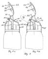
- FIGS 1 to 6 show a first embodiment of the spray head according to the invention for foam or gel products.
- the spray head has a hood-shaped, plate-spanning attachment element 10, on which an actuating element 12 is movable is attached.
- the actuating element 12 with the attachment element connected and the actuating element is pivotally mounted in the attachment element 10th held.
- the actuating element 12 has a pressure region 14 which is in the direction of actuation A of the valve exerted force via a pipe 15 to a valve and that's how it works.
- the nozzle 15 opens into the outlet opening 16 of the Actuating element.
- the outlet opening is provided in a wall element, that is held by a funnel-shaped wall portion.
- the article 10 has an opening in which the actuator 12 with his Pressure range 14 is freely accessible. From a second opening 20 of the essay 10, the actuator with its opening 16 is slightly ahead. Will the actuator Pressed 12 in the area 14, so the actuator 12 is the Opening 20 partially free, especially in the region of the tip of the attachment element (see Fig. 1d).
- FIG. 1d shows by way of example a leaking foam.
- a closure flap 22 is articulated in a region 24.
- the Shutter 22 is in shape to the top 10 and the actuator 12 adapted in the region of its outlet opening, so that the article in the closed Position has a continuous contour.
- the area 24 is between the first opening 18 and second opening 20.
- the flap 22 has her pointing away from the articulation end a pin-shaped locking projection 26.
- Inside the flap is a hollow pin 28 as above Molded portion which in the closed position of the flap 22 in the Outlet opening 16 dives and this closes.
- the projection 26 in a bore 30 (see Fig. 1b) in the actuator disposed below the outlet opening 16. hereby the position of the actuator is determined. This is still supported in that the closure flap 22 is flat on the attachment 10 in the region 31 is applied.
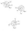
- FIGS. 2a to 2d show a perspective view of the spray head from FIG. 1, wherein like elements are provided with like reference numerals.
- the pressure region 14 is a substantially has oval shape.
- the wall is 33 of the essay 10 deeper drawn in the pressure range.
- FIG. 3 shows a detailed view of the connection of actuating element 12 and Attachment 10.
- the corresponding connection is shown in FIG. 1 by the reference numeral 35 characterized.
- Actuator 12 and attachment 10 are connected via a web 37 with each other connected.
- the web 37 opens into the outer surface of the actuating element 12 forming a T-shaped connection, while the web 37 from the end of the essay 10 is formed.
- FIG. 4 shows a detailed view of an additional inner seal 39 which is shown in FIG Shutter 22 is formed.
- the additional seal 39 is circular Bead is formed, which in the closed position of the flap against the actuating element in the area around the outlet opening 16 abuts.
- Figure 5 shows the locking mechanism in detail.
- the pin 26 with a rounded Tip extends through the opening 31 in the actuator and protrudes from the inside of the flap 22.
- FIGS. 6a to 6e show a perspective view of the spray head from FIG. 1 in FIG his open position. Same elements are again with the same reference numerals Provided. From Figure 6a can be clearly seen that the outlet opening 16th is formed star-shaped, wherein from a central bore 16 from outlet slots 43 protrude radially. Also in Figure 6a it can be seen that around the outlet slots 43 around a paragraph 45 is provided in the actuator, the is sealed over the bead 39.
- FIG. 6 a shows a perspective view from the front
- FIG. 6 b shows a perspective view View with open flap 22 from the side
- FIG. 6c shows the spray head from behind with a plan view of the printing area 14.
- Figure FIG. 6d is a sectional view substantially corresponding to FIG Spray cap is not placed on a container.
- FIG. 6e shows the spray cap in FIG a perspective view from above.
- Figure 6f is a detail view of the connector 24. From the article is in Area of the tip a projection 47 before. Over a range with diminished Thickness of the projection 47 goes into a projection 45, which consists of the closure flap 22 protrudes.
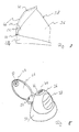
- Figure 7 shows an alternative embodiment of the invention Spray nozzle.
- the spray head has a cap 34, from the the actuator 36 protrudes.
- the actuator 36 has a Pressure range 38.
- the opening 40 is slightly offset arranged on the tip of the actuator 36.
- the outlet opening 40 is again star-shaped and in a circular planar portion 42 is arranged.
- the outlet opening 40 is closed by a on the attachment 34 in the area 44 hinged flap 46.
- FIG. 8 shows the flap 46 in its open position, while FIG closed position shown. At its end pointing away from the essay 34 the flap 46 has an insert 48 with star-shaped projections 50. In the closed position of the flap 46, they close the star-shaped outlet opening 40th
- the flap 46 is provided with a projection 52 Provided.
- the projection 52 engages in a recess 54 in the actuating element 46.
Abstract
Description
Die vorliegende Erfindung betrifft einen Sprühkopf zum Austragen von Schaum, Gel oder einem ähnlichen Medium aus einem Behälter.The present invention relates to a spray head for discharging foam, Gel or similar medium from a container.
Sprühköpfe für Schaum- oder Gelprodukte sind hinlänglich bekannt. Sie besitzen häufig ein tellerübergreifendes Aufsatzelement, das mit einem Behälter für das Medium verbindbar ist. Ferner ist ein relativ zum Aufsatzelement bewegliches Betätigungselement vorgesehen, das eine Austrittsöffnung und einen Druckabschnitt aufweist. Die Austrittsöffnung ist dabei über einen Stutzen mit einer Ventilöffnung des Behälters verbunden. Das Ventil wird über den Druckabschnitt durch Druck auf den Stutzen betätigt. Nach Gebrauch kann der Sprühkopf durch ein Überkappe verschlossen werden.Spray heads for foam or gel products are well known. You own often a cross-plate essay element with a container for the Medium is connectable. Furthermore, a relative to the attachment element is movable Actuator provided, which has an outlet opening and a pressure section having. The outlet opening is via a connection with a valve opening connected to the container. The valve is pressurized through the pressure section operated the neck. After use, the spray head can be closed by an overcap become.
Der vorliegenden Erfindung liegt die Aufgabe zugrunde, einen Sprühkopf für Schäume oder Gele zur Verfügung zu stellen, der mit einfachen Mitteln ein ungewolltes Auslösen des Sprühkopfes verhindert und eine Austrittsöffnung abdichtet.The present invention has for its object to provide a spray head for To provide foams or gels, the unintentional by simple means Triggering of the spray head prevents and seals an outlet opening.
Erfindungsgemäß wird die Aufgabe durch einen Sprühkopf mit den Merkmalen aus Anspruch 1 gelöst. Vorteilhafte Ausgestaltungen bilden den Gegenstand der Unteransprüche.According to the invention the object is achieved by a spray head with the features Claim 1 solved. Advantageous embodiments form the subject of the Dependent claims.
Bei dem erfindungsgemäßen Sprühkopf zum Austragen von Schaum, Gel oder einem anderen Medium aus einem mit einem Ventil versehenen Behälter sind ein Aufsatzelement und ein Betätigungselement vorgesehen. Das Aufsatzelement sitzt auf dem Behälter, vorzugsweise tellerübergreifend. In dem Aufsatzelement ist das Betätigungselement beweglich gelagert. Das Betätigungselement besitzt eine Austrittsöffnung und einen Druckabschnitt, wobei es nicht erforderlich ist, daß der Druckabschnitt besonders ausgestaltet oder gekennzeichnet ist. Die Austrittsöffnung des Betätigungselements ist über einen Stutzen mit der Ventilöffnung verbunden. Bei einem Druck auf den Druckabschnitt des Betätigungselements wird das Ventil geöffnet und das in dem Behälter enthaltene Medium wird durch den Stutzen über die Austrittsöffnung ausgetragen. Ein an dem Aufsatzelement befestigtes Verschlußelement verschließt in seiner geschlossenen Position die Austrittsöffnung. Das Verschlußelement und das Betätigungselement besitzen eine Verriegelungseinrichtung, die in der geschlossenen Position des Verschlußelements ein Auslösen des Betätigungselements sperrt. Das Verschlußelement ist an dem Aufsatzelement angelenkt. Über die Verriegelungseinrichtung wird in der geschlossenen Position auch die Position des Betätigungselements relativ zu dem Behälter festgelegt, so daß eine versehentliche Betätigung des Ventils nicht erfolgen kann. Bei dem erfindungsgemäßen Sprühkopf kann auf eine Überkappe verzichtet werden, da eine unbeabsichtigte Betätigung bereits durch das Verschlußelement vermieden wird. Hinzu kommt, daß das Verschlußelement in seiner verriegelten Stellung auch die Austrittsöffnung verschließt und somit die Bildung und/oder den Austritt von Schaumoder Gelresten verhindert.In the spray head according to the invention for discharging foam, gel or another medium from a valved container is a Attachment and an actuator provided. The attachment sits on the container, preferably plate-spreading. In the attachment element is the Actuator movably mounted. The actuating element has an outlet opening and a printing section, wherein it is not necessary that the Printing section is particularly designed or marked. The outlet opening of the actuating element is connected via a connecting piece with the valve opening. At a pressure on the pressure section of the actuating element, the valve opened and the medium contained in the container is through the nozzle over discharged the outlet. A fastener attached to the attachment element closes the outlet opening in its closed position. The Closure element and the actuating element have a locking device, in the closed position of the closure element triggering the Actuator locks. The closure element is on the attachment element hinged. About the locking device is in the closed position also determines the position of the actuating element relative to the container, so that accidental operation of the valve can not be done. In the inventive Spray head can be dispensed with an overcap, as an unintentional Operation is already avoided by the closure element. in addition comes that the closure element in its locked position and the outlet opening closes and thus the formation and / or the escape of foam or Gel residue prevented.
In einer bevorzugten Ausgestaltung besteht die Verriegelungseinrichtung aus einer Ausnehmung und einem Vorsprung, die in der geschlossenen Position des Verschlußelements ineinandergreifen. Hierdurch wird ein Auslösen des Betätigungselements gesperrt. Bevorzugt ist das Verschlußelement mit einem stiftförmigen Vorsprung versehen, der in der geschlossenen Position in eine Ausnehmung in dem korrespondierenden Betätigungselement eingreift. Der Vorsprung verriegelt das Betätigungselement derart, daß das Ventil des Behälters geschlossen ist. In a preferred embodiment, the locking device consists of a Recess and a projection in the closed position of the closure element mesh. As a result, a triggering of the actuating element blocked. Preferably, the closure element with a pin-shaped projection provided in the closed position in a recess in the corresponding Actuator engages. The projection locks the actuator such that the valve of the container is closed.
Um ein Nachschäumen des Sprühkopfs wirksam zu verhindern, können auf der Innenseite des Verschlußelements vorstehende Abschnitte angeordnet sein, die in der geschlossenen Position des Verschlußelements in die Austrittsöffnung vorstehen. Ist die Austrittsöffnung beispielsweise sternförmig ausgebildet, so kann auch der vorstehende Abschnitt sternförmig ausgebildet sein, um in die Austrittsöffnung vorzustehen. Der vorstehende Abschnitt kann aber auch teilweise in die Austrittsöffnung vorstehen. Befindet sich bei dem erfindungsgemäßen Sprühkopf das Verschlußelement in seiner geschlossenen Position, so ist das Betätigungselement gesperrt und die Austrittsöffnung durch den vorstehenden Abschnitt abgedichtet, so daß ein Nachschäumen unterbleibt und eine versehentliche Betätigung ausgeschlossen ist. Der vorstehende Abschnitt kann einstückig in dem Verschlußelement ausgeformt sein.To effectively prevent re-foaming of the spray head, on the Be arranged inside the closure element projecting portions, which in protrude the closed position of the closure element in the outlet opening. If the outlet opening is, for example, star-shaped, then so can the projecting portion may be formed in a star shape to enter the exit opening preside. The above section may also be partially in the outlet opening protrude. The closure element is located in the spray head according to the invention in its closed position, so is the actuator locked and the outlet opening sealed by the protruding portion, so that a Nachschäumen omitted and precluded accidental operation is. The protruding portion may be integrally formed in the closure member his.
In einer alternativen Ausgestaltung ist das Verschlußelement mit einem Einsatz versehen, der den vorstehenden Abschnitt für die Austrittsöffnung trägt. Der Einsatz kann fest in das Verschlußelement eingesetzt werden.In an alternative embodiment, the closure element is provided with an insert, which carries the protruding portion for the outlet opening. The use can be used firmly in the closure element.
In einer möglichen Ausgestaltung besitzt das Aufsatzelement mindestens zwei Öffnungen, von denen in einer ersten Öffnung der Druckbereich des Betätigungselements und in der zweiten Öffnung die Austrittsöffnung des Betätigungselements frei liegt. In dieser Ausgestaltung des Sprühkopfs ist das Verschlußelement in einem Bereich zwischen erster und zweiter Öffnung an der Spitze des Aufsatzelements angelenkt. Das Verschlußelement trägt hierbei bevorzugt an seinem von der Anlenkung fortweisenden Ende den Vorsprung der Verriegelungseinrichtung, der in das Betätigungselement eingreift.In a possible embodiment, the attachment element has at least two openings, of which in a first opening the pressure area of the actuating element and in the second opening, the outlet opening of the actuating element is free. In this embodiment of the spray head, the closure element is in one Area between first and second opening at the top of the attachment element hinged. The closure element hereby preferably bears at its from the articulation pointing end the projection of the locking device, which in the Actuator engages.
In einer alternativen Ausgestaltung ist das Aufsatzelement mit einer gemeinsamen Öffnung für das gesamte Betätigungselement ausgestaltet, aus der dieses mit seiner Austrittsöffnung und dem Betätigungsabschnitt vorsteht. Bei dieser Ausgestaltung ist das Aufsatzelement im wesentlichen in Form eines Rings ausgebildet. Das Verschlußelement kann bei dieser Ausgestaltung in seinem nahe zur Anlenkung liegendem Ende mit einem Vorsprung als Teil der Verriegelungseinrichtung versehen sein.In an alternative embodiment, the attachment element with a common Opening designed for the entire actuator, from this with his Outlet opening and the actuating portion protrudes. In this embodiment the attachment element is formed substantially in the form of a ring. The closure element can in this embodiment in his lying close to the articulation End be provided with a projection as part of the locking device.
Das Verschlußelement ist bevorzugt in Form einer Klappe ausgeführt, die weniger als eine Hälfte des Sprühkopfes bedeckt.The closure element is preferably designed in the form of a flap, the less covered as a half of the spray head.
Nachfolgend werden zwei Ausführungsbeispiele des erfindungsgemäßen Sprühkopfes anhand von Zeichnungen näher erläutert. Es zeigt:
- Fig. 1
- ein erstes Beispiel für einen erfindungsgemäßen Sprühkopf in unterschiedlichen Positionen der Verschlußklappe,
- Fig. 2a bis 2d
- den Sprühkopf aus Fig. 1 in einer perspektivischen Ansicht,
- Fig. 3
- eine Detailansicht der Verbindung von Betätigungselement und Aufsatz,
- Fig. 4
- einen innerem Dichtring in dem Verschlußelement in einer Detailansicht,
- Fig. 5
- eine Verriegelungseinrichtung in einer Detailansicht,
- Fig. 6a bis 6f
- eine perspektivische Ansicht des Sprühkopfes aus Fig. 1 und eine Detailansicht zu der Verbindung von Verschlußklappe und Aufsatzelement,
- Fig. 7
- eine zweite Ausgestaltung des erfindungsgemäßen Sprühkopfes in der Seitenansicht und
- Fig. 8
- den Sprühkopf aus Fig. 7 in einer perspektivischen Ansicht.
- Fig. 1
- a first example of a spray head according to the invention in different positions of the closure flap,
- Fig. 2a to 2d
- the spray head of Fig. 1 in a perspective view,
- Fig. 3
- a detailed view of the connection of the actuator and essay,
- Fig. 4
- an inner sealing ring in the closure element in a detailed view,
- Fig. 5
- a locking device in a detailed view,
- Fig. 6a to 6f
- a perspective view of the spray head of Figure 1 and a detailed view of the connection of the flap and attachment element,
- Fig. 7
- a second embodiment of the spray head according to the invention in side view and
- Fig. 8
- the spray head of Fig. 7 in a perspective view.
Figuren 1 bis 6 zeigen eine erste Ausgestaltung des erfindungsgemäßen Sprühkopfes
für Schaum- oder Gelprodukte. Der Sprühkopf besitzt ein haubenförmiges,
tellerübergreifendes Aufsatzelement 10, an dem ein Betätigungselement 12 beweglich
befestigt ist. Hierbei ist das Betätigungselement 12 mit dem Aufsatzelement
verbunden und das Betätigungselement ist schwenkbar in dem Aufsatzelement 10
gehalten.Figures 1 to 6 show a first embodiment of the spray head according to the invention
for foam or gel products. The spray head has a hood-shaped,
plate-spanning
Das Betätigungselement 12 besitzt einen Druckbereich 14, der eine in Betätigungsrichtung
A des Ventils ausgeübte Kraft über einen Stutzen 15 an ein Ventil weiterleitet
und dieses so betätigt. Der Stutzen 15 mündet in der Austrittsöffnung 16 des
Betätigungselements. Die Austrittsöffnung ist in einem Wandelement vorgesehen,
daß von einem trichterförmigen Wandabschnitt gehalten ist.The
Der Aufsatz 10 besitzt eine Öffnung, in der das Betätigungselement 12 mit seinem
Druckbereich 14 frei zugänglich liegt. Aus einer zweiten Öffnung 20 des Aufsatzes
10 steht das Betätigungselement mit seiner Öffnung 16 leicht vor. Wird das Betätigungselement
12 im Bereich 14 gedrückt, so gibt das Betätigungselement 12 die
Öffnung 20 teilweise frei, insbesondere im Bereich der Spitze des Aufsatzelements
(vgl. Fig. 1d). Figur 1d zeigt mit B beispielhaft einen austretenden Schaum.The
An dem Aufsatz 10 ist eine Verschlußklappe 22 in einem Bereich 24 angelenkt. Die
Verschlußklappe 22 ist in ihrer Form an den Aufsatz 10 und das Betätigungselement
12 im Bereich seiner Austrittsöffnung angepaßt, so daß der Aufsatz in der geschlossenen
Position eine durchgehende Kontur besitzt. Der Bereich 24 liegt zwischen der
ersten Öffnung 18 und der zweiten Öffnung 20. Die Verschlußklappe 22 besitzt an
ihrem von der Anlenkung fortweisenden Ende einen stiftförmigen Verriegelungsvorsprung
26. Im inneren der Verschlußklappe ist ein Hohlzapfen 28 als vorstehender
Abschnitt angeformt, der in der geschlossenen Position der Klappe 22 in die
Austrittsöffnung 16 taucht und diese verschließt. In der in Fig. 1a dargestellten
geschlossenen Position, ist der Vorsprung 26 in einer Bohrung 30 (vgl. Fig. 1b) in
dem Betätigungselement unterhalb der Austrittsöffnung 16 angeordnet. Hierdurch
wird die Position des Betätigungselements festgelegt. Unterstützt wird dies noch
dadurch, daß die Verschlußklappe 22 an dem Aufsatz 10 im Bereich 31 flächig
anliegt.At the top 10, a
Figuren 2a bis 2d zeigen eine perspektivische Ansicht des Sprühkopfes aus Fig. 1,
wobei gleiche Elemente mit gleichen Bezugszeichen versehen sind. In der Darstellung
von Figur 2 ist zu erkennen, daß der Druckbereich 14 eine im wesentlichen
ovale Form besitzt. Wie in Figur 2b und 2c deutlich zu erkennen, ist die Wandung
33 des Aufsatzes 10 im Druckbereich tiefergezogen.FIGS. 2a to 2d show a perspective view of the spray head from FIG. 1,
wherein like elements are provided with like reference numerals. In the presentation
From Figure 2 it can be seen that the
Figur 3 zeigt eine Detailansicht zur Verbindung von Betätigungselement 12 und
Aufsatz 10. Die entsprechende Verbindung ist in Figur 1 mit dem Bezugszeichen 35
gekennzeichnet. Betätigungselement 12 und Aufsatz 10 sind über einen Steg 37 miteinander
verbunden. Der Steg 37 mündet in die Außenfläche des Betätigungselements
12 einen t-förmigen Anschluß bildend, während der Steg 37 aus dem Ende
des Aufsatzes 10 herausgeformt ist.FIG. 3 shows a detailed view of the connection of actuating
Figur 4 zeigt die Detailansicht einer zusätzlichen inneren Dichtung 39, die in der
Verschlußklappe 22 angeformt ist. Die zusätzliche Dichtung 39 ist als kreisförmiger
Wulst ausgebildet, der in der verschlossenen Position der Klappe gegen das Betätigungselement
im Bereich um die Austrittsöffnung 16 anliegt. FIG. 4 shows a detailed view of an additional
Figur 5 zeigt den Verriegelungsmechanismus im Detail. Der Stift 26 mit einer abgerundeten
Spitze reicht durch die Öffnung 31 in dem Betätigungselement durch und
steht aus der Innenseite der Verschlußklappe 22 vor. Zum besseren Halt der Verschlußklappe
in der Verriegelungsposition ist in der Öffnung 31 ein umlaufender
Wulst 41 ausgeformt, dessen Innendurchmesser dem Außendurchmesser des Stifts
26 entspricht.Figure 5 shows the locking mechanism in detail. The
Figuren 6a bis 6e zeigen eine perspektivische Ansicht des Sprühkopfs aus Figur 1 in
seiner geöffneten Position. Gleiche Elemente sind wieder mit gleichen Bezugszeichen
versehen. Aus Figur 6a ist deutlich zu erkennen, daß die Austrittsöffnung 16
sternförmig ausgebildet ist, wobei von einer zentralen Bohrung 16 aus Austrittsschlitze
43 radial abstehen. Ebenfalls in Figur 6a ist zu erkennen, daß um die Austrittsschlitze
43 herum ein Absatz 45 in dem Betätigungselement vorgesehen ist, der
über den Wulst 39 abgedichtet wird.FIGS. 6a to 6e show a perspective view of the spray head from FIG. 1 in FIG
his open position. Same elements are again with the same reference numerals
Provided. From Figure 6a can be clearly seen that the outlet opening 16th
is formed star-shaped, wherein from a
Figur 6a zeigt eine perspektivische Ansicht von vorne, während Figur 6b eine perspektivische
Ansicht bei geöffneter Verschlußklappe 22 von der Seite zeigt. Figur 6c
zeigt den Sprühkopf von hinten mit einer Draufsicht auf den Druckbereich 14. Figur
6d zeigt eine Schnittansicht, die im wesentlichen Figur 1 entspricht, wobei die
Sprühkappe nicht auf einen Behälter aufgesetzt ist. Figur 6e zeigt die Sprühkappe in
einer perspektivischen Ansicht von oben.FIG. 6 a shows a perspective view from the front, while FIG. 6 b shows a perspective view
View with
Figur 6f ist eine Detailansicht des Verbindungsstücks 24. Aus dem Aufsatz steht im
Bereich der Spitze ein Vorsprung 47 vor. Über einen Bereich mit verminderter
Wandstärke geht der Vorsprung 47 in einen Vorsprung 45 über, der aus der Verschlußklappe
22 vorsteht. Figure 6f is a detail view of the
Figur 7 zeigt ein alternatives Ausführungsbeispiel für den erfindungsgemäßen
Sprühkopf. In dieser Ausgestaltung besitzt der Sprühkopf einen Aufsatz 34, aus dem
das Betätigungselement 36 vorsteht. Das Betätigungselement 36 besitzt einen
Druckbereich 38. Wie in Figur 7 deutlich zu erkennen, ist die Öffnung 40 leicht versetzt
auf der Spitze des Betätigungselements 36 angeordnet. Auch in diesem Ausführungsbeispiel
ist die Austrittsöffnung 40 wieder sternförmig ausgebildet und in
einem kreisförmigen ebenem Abschnitt 42 angeordnet.Figure 7 shows an alternative embodiment of the invention
Spray nozzle. In this embodiment, the spray head has a
Verschlossen wird die Austrittsöffnung 40 durch eine an dem Aufsatz 34 im Bereich
44 angelenkte Klappe 46.The
Figur 8 zeigt die Klappe 46 in ihrer geöffneten Position, während Figur 7 die
geschlossene Position dargestellt. An ihrem von dem Aufsatz 34 fortweisenden Ende
besitzt die Klappe 46 einen Einsatz 48 mit sternförmigen Vorsprüngen 50. In der
geschlossenen Position der Klappe 46 verschließen diese die sternförmige Austrittsöffnung
40.FIG. 8 shows the
An dem zum Aufsatz weisenden Ende ist die Klappe 46 mit einem Vorsprung 52
versehen. Der Vorsprung 52 greift in eine Ausnehmung 54 in dem Betätigungselement
46 ein. Hierdurch wird das Betätigungselement 36 in seiner Position relativ
zu dem Aufsatz 34 und somit zu dem Behälter festgelegt, so daß kein Austrag des
Mediums in der geschlossenen Position der Klappe erfolgen kann.At the end facing the attachment, the
Claims (12)
Applications Claiming Priority (2)
| Application Number | Priority Date | Filing Date | Title |
|---|---|---|---|
| DE20308449U DE20308449U1 (en) | 2003-05-30 | 2003-05-30 | Spray head for foams or gels |
| DE20308449U | 2003-05-30 |
Publications (2)
| Publication Number | Publication Date |
|---|---|
| EP1481734A1 true EP1481734A1 (en) | 2004-12-01 |
| EP1481734B1 EP1481734B1 (en) | 2006-05-10 |
Family
ID=33103747
Family Applications (1)
| Application Number | Title | Priority Date | Filing Date |
|---|---|---|---|
| EP04003977A Expired - Lifetime EP1481734B1 (en) | 2003-05-30 | 2004-02-21 | Closure for a spray head |
Country Status (5)
| Country | Link |
|---|---|
| EP (1) | EP1481734B1 (en) |
| AT (1) | ATE325660T1 (en) |
| DE (2) | DE20308449U1 (en) |
| ES (1) | ES2262044T3 (en) |
| PT (1) | PT1481734E (en) |
Cited By (2)
| Publication number | Priority date | Publication date | Assignee | Title |
|---|---|---|---|---|
| USD942586S1 (en) | 2018-11-27 | 2022-02-01 | Church & Dwight Co., Inc. | Front band on a spray nozzle |
| EP3974344A4 (en) * | 2019-05-21 | 2023-02-01 | Aptar do Brasil Embalagens Ltda. | Dispensing device for pressurized fluids with anti-actuation system |
Families Citing this family (2)
| Publication number | Priority date | Publication date | Assignee | Title |
|---|---|---|---|---|
| DE102005015696B4 (en) | 2005-04-05 | 2012-05-24 | Vogelsang-Holding Ag | Spray can |
| DE202011000160U1 (en) | 2011-01-21 | 2012-04-23 | Lindal Dispenser Gmbh | spray nozzle |
Citations (2)
| Publication number | Priority date | Publication date | Assignee | Title |
|---|---|---|---|---|
| US3904088A (en) * | 1972-10-18 | 1975-09-09 | Sr Benjamin K Milbourne | Safety closure for an aerosol container |
| WO2002043872A2 (en) * | 2000-12-01 | 2002-06-06 | Dispensing Patents International Llc | Spray dispensing device with nozzle closure |
-
2003
- 2003-05-30 DE DE20308449U patent/DE20308449U1/en not_active Expired - Lifetime
-
2004
- 2004-02-21 AT AT04003977T patent/ATE325660T1/en not_active IP Right Cessation
- 2004-02-21 PT PT04003977T patent/PT1481734E/en unknown
- 2004-02-21 EP EP04003977A patent/EP1481734B1/en not_active Expired - Lifetime
- 2004-02-21 DE DE502004000527T patent/DE502004000527D1/en not_active Expired - Lifetime
- 2004-02-21 ES ES04003977T patent/ES2262044T3/en not_active Expired - Lifetime
Patent Citations (2)
| Publication number | Priority date | Publication date | Assignee | Title |
|---|---|---|---|---|
| US3904088A (en) * | 1972-10-18 | 1975-09-09 | Sr Benjamin K Milbourne | Safety closure for an aerosol container |
| WO2002043872A2 (en) * | 2000-12-01 | 2002-06-06 | Dispensing Patents International Llc | Spray dispensing device with nozzle closure |
Cited By (2)
| Publication number | Priority date | Publication date | Assignee | Title |
|---|---|---|---|---|
| USD942586S1 (en) | 2018-11-27 | 2022-02-01 | Church & Dwight Co., Inc. | Front band on a spray nozzle |
| EP3974344A4 (en) * | 2019-05-21 | 2023-02-01 | Aptar do Brasil Embalagens Ltda. | Dispensing device for pressurized fluids with anti-actuation system |
Also Published As
| Publication number | Publication date |
|---|---|
| PT1481734E (en) | 2006-08-31 |
| DE502004000527D1 (en) | 2006-06-14 |
| ATE325660T1 (en) | 2006-06-15 |
| ES2262044T3 (en) | 2006-11-16 |
| DE20308449U1 (en) | 2004-10-14 |
| EP1481734B1 (en) | 2006-05-10 |
Similar Documents
| Publication | Publication Date | Title |
|---|---|---|
| DE60133073T2 (en) | Dispensing unit for the simultaneous dispensing of two products | |
| EP1471013B9 (en) | Spray cap | |
| EP3094414B1 (en) | Dispensing device | |
| DE3829023A1 (en) | TIP LOCK FOR A CONTAINER | |
| DE69818004T2 (en) | Dispensing head for dispensing a product and a dispensing device provided with such a dispensing head | |
| DE3803229A1 (en) | DISPENSER FOR PORTIONED ISSUE OF PASTOESER MASS | |
| EP0301135A1 (en) | Container closure with retractable turnspout | |
| DE102004057704A1 (en) | Cap, for an aerosol/spray can, has a folded acoustic seal at the button as an elastic link between it and the cap | |
| DE102006036517A1 (en) | Dispensing head for a pressurized container receiving a flowable medium | |
| EP0390974A1 (en) | Closure device for flexible liquid containers | |
| EP1481734B1 (en) | Closure for a spray head | |
| DE2425951B2 (en) | SINGLE-PIECE DESIGNED SPRAY HEAD FOR AN AEROSOL PRESSURE CAN AND MOLD FOR ITS PRODUCTION | |
| EP1118554A1 (en) | Spray cap with integral head | |
| EP1586514B1 (en) | Atomiser for a container with a valve | |
| DE7903111U1 (en) | Lock arrangement | |
| WO2003026983A1 (en) | Self-closing distribution head for a pressure vessel | |
| DE69910452T2 (en) | Delayed closing valve | |
| EP1739032B1 (en) | Dispensing head for a container having a valve for dispensing a fluid | |
| DE19533134A1 (en) | Container closure for cosmetics or perfume containers | |
| DE19650566A1 (en) | Dispenser system | |
| DE19681702B4 (en) | Two-component aerosol can | |
| DE2433656C2 (en) | Valve actuation device, in particular for extinguishing agent containers | |
| DE20314632U1 (en) | Dispenser head for a pressure pack | |
| EP1262416A2 (en) | Container for recieving and dispensing of fluid material | |
| DE7623770U1 (en) | Container for an aerosol dispenser |
Legal Events
| Date | Code | Title | Description |
|---|---|---|---|
| PUAI | Public reference made under article 153(3) epc to a published international application that has entered the european phase |
Free format text: ORIGINAL CODE: 0009012 |
|
| 17P | Request for examination filed |
Effective date: 20040824 |
|
| AK | Designated contracting states |
Kind code of ref document: A1 Designated state(s): AT BE BG CH CY CZ DE DK EE ES FI FR GB GR HU IE IT LI LU MC NL PT RO SE SI SK TR |
|
| AX | Request for extension of the european patent |
Extension state: AL LT LV MK |
|
| 17Q | First examination report despatched |
Effective date: 20050208 |
|
| AKX | Designation fees paid |
Designated state(s): AT BE BG CH CY CZ DE DK EE ES FI FR GB GR HU IE IT LI LU MC NL PT RO SE SI SK TR |
|
| GRAP | Despatch of communication of intention to grant a patent |
Free format text: ORIGINAL CODE: EPIDOSNIGR1 |
|
| GRAS | Grant fee paid |
Free format text: ORIGINAL CODE: EPIDOSNIGR3 |
|
| GRAA | (expected) grant |
Free format text: ORIGINAL CODE: 0009210 |
|
| AK | Designated contracting states |
Kind code of ref document: B1 Designated state(s): AT BE BG CH CY CZ DE DK EE ES FI FR GB GR HU IE IT LI LU MC NL PT RO SE SI SK TR |
|
| PG25 | Lapsed in a contracting state [announced via postgrant information from national office to epo] |
Ref country code: IT Free format text: LAPSE BECAUSE OF FAILURE TO SUBMIT A TRANSLATION OF THE DESCRIPTION OR TO PAY THE FEE WITHIN THE PRESCRIBED TIME-LIMIT;WARNING: LAPSES OF ITALIAN PATENTS WITH EFFECTIVE DATE BEFORE 2007 MAY HAVE OCCURRED AT ANY TIME BEFORE 2007. THE CORRECT EFFECTIVE DATE MAY BE DIFFERENT FROM THE ONE RECORDED. Effective date: 20060510 Ref country code: SI Free format text: LAPSE BECAUSE OF FAILURE TO SUBMIT A TRANSLATION OF THE DESCRIPTION OR TO PAY THE FEE WITHIN THE PRESCRIBED TIME-LIMIT Effective date: 20060510 Ref country code: RO Free format text: LAPSE BECAUSE OF FAILURE TO SUBMIT A TRANSLATION OF THE DESCRIPTION OR TO PAY THE FEE WITHIN THE PRESCRIBED TIME-LIMIT Effective date: 20060510 Ref country code: SK Free format text: LAPSE BECAUSE OF FAILURE TO SUBMIT A TRANSLATION OF THE DESCRIPTION OR TO PAY THE FEE WITHIN THE PRESCRIBED TIME-LIMIT Effective date: 20060510 Ref country code: FI Free format text: LAPSE BECAUSE OF FAILURE TO SUBMIT A TRANSLATION OF THE DESCRIPTION OR TO PAY THE FEE WITHIN THE PRESCRIBED TIME-LIMIT Effective date: 20060510 |
|
| REG | Reference to a national code |
Ref country code: GB Ref legal event code: FG4D Free format text: NOT ENGLISH |
|
| REG | Reference to a national code |
Ref country code: CH Ref legal event code: EP |
|
| REG | Reference to a national code |
Ref country code: SE Ref legal event code: TRGR |
|
| REG | Reference to a national code |
Ref country code: CH Ref legal event code: NV Representative=s name: ISLER & PEDRAZZINI AG |
|
| REF | Corresponds to: |
Ref document number: 502004000527 Country of ref document: DE Date of ref document: 20060614 Kind code of ref document: P |
|
| REG | Reference to a national code |
Ref country code: IE Ref legal event code: FG4D Free format text: LANGUAGE OF EP DOCUMENT: GERMAN |
|
| PG25 | Lapsed in a contracting state [announced via postgrant information from national office to epo] |
Ref country code: DK Free format text: LAPSE BECAUSE OF FAILURE TO SUBMIT A TRANSLATION OF THE DESCRIPTION OR TO PAY THE FEE WITHIN THE PRESCRIBED TIME-LIMIT Effective date: 20060810 |
|
| REG | Reference to a national code |
Ref country code: HU Ref legal event code: AG4A Ref document number: E000450 Country of ref document: HU |
|
| REG | Reference to a national code |
Ref country code: PT Ref legal event code: SC4A Effective date: 20060619 |
|
| GBT | Gb: translation of ep patent filed (gb section 77(6)(a)/1977) |
Effective date: 20060830 |
|
| REG | Reference to a national code |
Ref country code: GR Ref legal event code: EP Ref document number: 20060402443 Country of ref document: GR |
|
| REG | Reference to a national code |
Ref country code: ES Ref legal event code: FG2A Ref document number: 2262044 Country of ref document: ES Kind code of ref document: T3 |
|
| ET | Fr: translation filed | ||
| PG25 | Lapsed in a contracting state [announced via postgrant information from national office to epo] |
Ref country code: MC Free format text: LAPSE BECAUSE OF NON-PAYMENT OF DUE FEES Effective date: 20070228 |
|
| PLBE | No opposition filed within time limit |
Free format text: ORIGINAL CODE: 0009261 |
|
| STAA | Information on the status of an ep patent application or granted ep patent |
Free format text: STATUS: NO OPPOSITION FILED WITHIN TIME LIMIT |
|
| 26N | No opposition filed |
Effective date: 20070213 |
|
| REG | Reference to a national code |
Ref country code: CH Ref legal event code: PCAR Free format text: ISLER & PEDRAZZINI AG;POSTFACH 1772;8027 ZUERICH (CH) |
|
| PG25 | Lapsed in a contracting state [announced via postgrant information from national office to epo] |
Ref country code: EE Free format text: LAPSE BECAUSE OF FAILURE TO SUBMIT A TRANSLATION OF THE DESCRIPTION OR TO PAY THE FEE WITHIN THE PRESCRIBED TIME-LIMIT Effective date: 20060510 |
|
| PG25 | Lapsed in a contracting state [announced via postgrant information from national office to epo] |
Ref country code: CY Free format text: LAPSE BECAUSE OF FAILURE TO SUBMIT A TRANSLATION OF THE DESCRIPTION OR TO PAY THE FEE WITHIN THE PRESCRIBED TIME-LIMIT Effective date: 20060510 Ref country code: LU Free format text: LAPSE BECAUSE OF NON-PAYMENT OF DUE FEES Effective date: 20070221 |
|
| PG25 | Lapsed in a contracting state [announced via postgrant information from national office to epo] |
Ref country code: TR Free format text: LAPSE BECAUSE OF FAILURE TO SUBMIT A TRANSLATION OF THE DESCRIPTION OR TO PAY THE FEE WITHIN THE PRESCRIBED TIME-LIMIT Effective date: 20060510 |
|
| PGFP | Annual fee paid to national office [announced via postgrant information from national office to epo] |
Ref country code: CH Payment date: 20100225 Year of fee payment: 7 Ref country code: CZ Payment date: 20100310 Year of fee payment: 7 Ref country code: ES Payment date: 20100225 Year of fee payment: 7 Ref country code: HU Payment date: 20100322 Year of fee payment: 7 Ref country code: IE Payment date: 20100226 Year of fee payment: 7 Ref country code: PT Payment date: 20100316 Year of fee payment: 7 |
|
| PGFP | Annual fee paid to national office [announced via postgrant information from national office to epo] |
Ref country code: FR Payment date: 20100315 Year of fee payment: 7 Ref country code: IT Payment date: 20100325 Year of fee payment: 7 |
|
| PGFP | Annual fee paid to national office [announced via postgrant information from national office to epo] |
Ref country code: AT Payment date: 20100322 Year of fee payment: 7 Ref country code: GB Payment date: 20100225 Year of fee payment: 7 Ref country code: TR Payment date: 20100316 Year of fee payment: 7 |
|
| PGFP | Annual fee paid to national office [announced via postgrant information from national office to epo] |
Ref country code: BG Payment date: 20100224 Year of fee payment: 7 |
|
| PGFP | Annual fee paid to national office [announced via postgrant information from national office to epo] |
Ref country code: BE Payment date: 20100323 Year of fee payment: 7 Ref country code: DE Payment date: 20100409 Year of fee payment: 7 Ref country code: NL Payment date: 20100225 Year of fee payment: 7 |
|
| PGFP | Annual fee paid to national office [announced via postgrant information from national office to epo] |
Ref country code: SE Payment date: 20100225 Year of fee payment: 7 |
|
| PGFP | Annual fee paid to national office [announced via postgrant information from national office to epo] |
Ref country code: GR Payment date: 20100323 Year of fee payment: 7 |
|
| BERE | Be: lapsed |
Owner name: *LINDAL VENTIL G.M.B.H. Effective date: 20110228 |
|
| REG | Reference to a national code |
Ref country code: NL Ref legal event code: V1 Effective date: 20110901 |
|
| REG | Reference to a national code |
Ref country code: CH Ref legal event code: PL |
|
| REG | Reference to a national code |
Ref country code: SE Ref legal event code: EUG |
|
| GBPC | Gb: european patent ceased through non-payment of renewal fee |
Effective date: 20110221 |
|
| PG25 | Lapsed in a contracting state [announced via postgrant information from national office to epo] |
Ref country code: LI Free format text: LAPSE BECAUSE OF NON-PAYMENT OF DUE FEES Effective date: 20110228 Ref country code: PT Free format text: LAPSE BECAUSE OF NON-PAYMENT OF DUE FEES Effective date: 20110822 Ref country code: CH Free format text: LAPSE BECAUSE OF NON-PAYMENT OF DUE FEES Effective date: 20110228 |
|
| REG | Reference to a national code |
Ref country code: FR Ref legal event code: ST Effective date: 20111102 |
|
| REG | Reference to a national code |
Ref country code: IE Ref legal event code: MM4A |
|
| PG25 | Lapsed in a contracting state [announced via postgrant information from national office to epo] |
Ref country code: AT Free format text: LAPSE BECAUSE OF NON-PAYMENT OF DUE FEES Effective date: 20110221 Ref country code: BE Free format text: LAPSE BECAUSE OF NON-PAYMENT OF DUE FEES Effective date: 20110228 Ref country code: GR Free format text: LAPSE BECAUSE OF NON-PAYMENT OF DUE FEES Effective date: 20110902 Ref country code: HU Free format text: LAPSE BECAUSE OF NON-PAYMENT OF DUE FEES Effective date: 20110222 Ref country code: CZ Free format text: LAPSE BECAUSE OF NON-PAYMENT OF DUE FEES Effective date: 20110221 |
|
| PG25 | Lapsed in a contracting state [announced via postgrant information from national office to epo] |
Ref country code: NL Free format text: LAPSE BECAUSE OF NON-PAYMENT OF DUE FEES Effective date: 20110901 |
|
| REG | Reference to a national code |
Ref country code: DE Ref legal event code: R119 Ref document number: 502004000527 Country of ref document: DE Effective date: 20110901 |
|
| PG25 | Lapsed in a contracting state [announced via postgrant information from national office to epo] |
Ref country code: FR Free format text: LAPSE BECAUSE OF NON-PAYMENT OF DUE FEES Effective date: 20110228 Ref country code: IE Free format text: LAPSE BECAUSE OF NON-PAYMENT OF DUE FEES Effective date: 20110221 |
|
| PG25 | Lapsed in a contracting state [announced via postgrant information from national office to epo] |
Ref country code: GB Free format text: LAPSE BECAUSE OF NON-PAYMENT OF DUE FEES Effective date: 20110221 |
|
| REG | Reference to a national code |
Ref country code: ES Ref legal event code: FD2A Effective date: 20120411 |
|
| PG25 | Lapsed in a contracting state [announced via postgrant information from national office to epo] |
Ref country code: ES Free format text: LAPSE BECAUSE OF NON-PAYMENT OF DUE FEES Effective date: 20110222 |
|
| PG25 | Lapsed in a contracting state [announced via postgrant information from national office to epo] |
Ref country code: TR Free format text: LAPSE BECAUSE OF FAILURE TO SUBMIT A TRANSLATION OF THE DESCRIPTION OR TO PAY THE FEE WITHIN THE PRESCRIBED TIME-LIMIT Effective date: 20110221 |
|
| PG25 | Lapsed in a contracting state [announced via postgrant information from national office to epo] |
Ref country code: DE Free format text: LAPSE BECAUSE OF NON-PAYMENT OF DUE FEES Effective date: 20110901 |
|
| PG25 | Lapsed in a contracting state [announced via postgrant information from national office to epo] |
Ref country code: SE Free format text: LAPSE BECAUSE OF NON-PAYMENT OF DUE FEES Effective date: 20110222 Ref country code: BG Free format text: LAPSE BECAUSE OF NON-PAYMENT OF DUE FEES Effective date: 20111231 |
|
| PG25 | Lapsed in a contracting state [announced via postgrant information from national office to epo] |
Ref country code: IT Free format text: LAPSE BECAUSE OF NON-PAYMENT OF DUE FEES Effective date: 20110221 |