EP1480694B1 - Apparatus for reducing fat content of blood - Google Patents
Apparatus for reducing fat content of blood Download PDFInfo
- Publication number
- EP1480694B1 EP1480694B1 EP03705585A EP03705585A EP1480694B1 EP 1480694 B1 EP1480694 B1 EP 1480694B1 EP 03705585 A EP03705585 A EP 03705585A EP 03705585 A EP03705585 A EP 03705585A EP 1480694 B1 EP1480694 B1 EP 1480694B1
- Authority
- EP
- European Patent Office
- Prior art keywords
- blood
- compartment
- chamber
- pipe
- fat
- Prior art date
- Legal status (The legal status is an assumption and is not a legal conclusion. Google has not performed a legal analysis and makes no representation as to the accuracy of the status listed.)
- Expired - Lifetime
Links
- 239000008280 blood Substances 0.000 title claims abstract description 135
- 210000004369 blood Anatomy 0.000 title claims abstract description 135
- 239000000463 material Substances 0.000 claims description 13
- 230000017531 blood circulation Effects 0.000 claims description 8
- 238000007789 sealing Methods 0.000 claims description 8
- 230000007246 mechanism Effects 0.000 claims description 7
- 229920003023 plastic Polymers 0.000 claims description 7
- 239000004033 plastic Substances 0.000 claims description 4
- 238000013022 venting Methods 0.000 claims description 4
- 238000004891 communication Methods 0.000 claims description 3
- 239000012530 fluid Substances 0.000 claims 1
- 238000000926 separation method Methods 0.000 description 14
- 238000001356 surgical procedure Methods 0.000 description 12
- 238000001816 cooling Methods 0.000 description 8
- 238000000034 method Methods 0.000 description 7
- 238000010276 construction Methods 0.000 description 5
- 229920002678 cellulose Polymers 0.000 description 4
- 239000001913 cellulose Substances 0.000 description 4
- 238000013461 design Methods 0.000 description 4
- 239000000835 fiber Substances 0.000 description 4
- 229920000728 polyester Polymers 0.000 description 4
- 210000001367 artery Anatomy 0.000 description 3
- 238000010438 heat treatment Methods 0.000 description 3
- 239000007788 liquid Substances 0.000 description 3
- 230000008569 process Effects 0.000 description 3
- 239000006096 absorbing agent Substances 0.000 description 2
- 230000000740 bleeding effect Effects 0.000 description 2
- 238000007675 cardiac surgery Methods 0.000 description 2
- 239000002826 coolant Substances 0.000 description 2
- 238000001914 filtration Methods 0.000 description 2
- 210000004072 lung Anatomy 0.000 description 2
- 238000012544 monitoring process Methods 0.000 description 2
- 230000037361 pathway Effects 0.000 description 2
- 239000007787 solid Substances 0.000 description 2
- 238000012546 transfer Methods 0.000 description 2
- 230000000007 visual effect Effects 0.000 description 2
- 206010073734 Microembolism Diseases 0.000 description 1
- 239000004952 Polyamide Substances 0.000 description 1
- 239000011358 absorbing material Substances 0.000 description 1
- 230000009471 action Effects 0.000 description 1
- 230000000735 allogeneic effect Effects 0.000 description 1
- 230000004075 alteration Effects 0.000 description 1
- 230000036760 body temperature Effects 0.000 description 1
- 210000004556 brain Anatomy 0.000 description 1
- 230000002612 cardiopulmonary effect Effects 0.000 description 1
- 239000011248 coating agent Substances 0.000 description 1
- 238000000576 coating method Methods 0.000 description 1
- 239000000549 coloured material Substances 0.000 description 1
- 230000003073 embolic effect Effects 0.000 description 1
- 238000005516 engineering process Methods 0.000 description 1
- 238000005188 flotation Methods 0.000 description 1
- 238000005187 foaming Methods 0.000 description 1
- 230000001900 immune effect Effects 0.000 description 1
- 150000002632 lipids Chemical class 0.000 description 1
- 239000008206 lipophilic material Substances 0.000 description 1
- 239000007791 liquid phase Substances 0.000 description 1
- 238000012986 modification Methods 0.000 description 1
- 230000004048 modification Effects 0.000 description 1
- 230000009251 neurologic dysfunction Effects 0.000 description 1
- 208000015015 neurological dysfunction Diseases 0.000 description 1
- 239000002245 particle Substances 0.000 description 1
- 229920002647 polyamide Polymers 0.000 description 1
- 229920000098 polyolefin Polymers 0.000 description 1
- 229920002620 polyvinyl fluoride Polymers 0.000 description 1
- 230000002980 postoperative effect Effects 0.000 description 1
- 238000012545 processing Methods 0.000 description 1
- XLYOFNOQVPJJNP-UHFFFAOYSA-N water Substances O XLYOFNOQVPJJNP-UHFFFAOYSA-N 0.000 description 1
Images


Classifications
-
- A—HUMAN NECESSITIES
- A61—MEDICAL OR VETERINARY SCIENCE; HYGIENE
- A61M—DEVICES FOR INTRODUCING MEDIA INTO, OR ONTO, THE BODY; DEVICES FOR TRANSDUCING BODY MEDIA OR FOR TAKING MEDIA FROM THE BODY; DEVICES FOR PRODUCING OR ENDING SLEEP OR STUPOR
- A61M1/00—Suction or pumping devices for medical purposes; Devices for carrying-off, for treatment of, or for carrying-over, body-liquids; Drainage systems
- A61M1/36—Other treatment of blood in a by-pass of the natural circulatory system, e.g. temperature adaptation, irradiation ; Extra-corporeal blood circuits
- A61M1/3621—Extra-corporeal blood circuits
- A61M1/3627—Degassing devices; Buffer reservoirs; Drip chambers; Blood filters
-
- A—HUMAN NECESSITIES
- A61—MEDICAL OR VETERINARY SCIENCE; HYGIENE
- A61M—DEVICES FOR INTRODUCING MEDIA INTO, OR ONTO, THE BODY; DEVICES FOR TRANSDUCING BODY MEDIA OR FOR TAKING MEDIA FROM THE BODY; DEVICES FOR PRODUCING OR ENDING SLEEP OR STUPOR
- A61M1/00—Suction or pumping devices for medical purposes; Devices for carrying-off, for treatment of, or for carrying-over, body-liquids; Drainage systems
- A61M1/36—Other treatment of blood in a by-pass of the natural circulatory system, e.g. temperature adaptation, irradiation ; Extra-corporeal blood circuits
- A61M1/3613—Reperfusion, e.g. of the coronary vessels, e.g. retroperfusion
-
- A—HUMAN NECESSITIES
- A61—MEDICAL OR VETERINARY SCIENCE; HYGIENE
- A61M—DEVICES FOR INTRODUCING MEDIA INTO, OR ONTO, THE BODY; DEVICES FOR TRANSDUCING BODY MEDIA OR FOR TAKING MEDIA FROM THE BODY; DEVICES FOR PRODUCING OR ENDING SLEEP OR STUPOR
- A61M1/00—Suction or pumping devices for medical purposes; Devices for carrying-off, for treatment of, or for carrying-over, body-liquids; Drainage systems
- A61M1/36—Other treatment of blood in a by-pass of the natural circulatory system, e.g. temperature adaptation, irradiation ; Extra-corporeal blood circuits
- A61M1/3621—Extra-corporeal blood circuits
- A61M1/3623—Means for actively controlling temperature of blood
-
- A—HUMAN NECESSITIES
- A61—MEDICAL OR VETERINARY SCIENCE; HYGIENE
- A61M—DEVICES FOR INTRODUCING MEDIA INTO, OR ONTO, THE BODY; DEVICES FOR TRANSDUCING BODY MEDIA OR FOR TAKING MEDIA FROM THE BODY; DEVICES FOR PRODUCING OR ENDING SLEEP OR STUPOR
- A61M2202/00—Special media to be introduced, removed or treated
- A61M2202/08—Lipoids
-
- A—HUMAN NECESSITIES
- A61—MEDICAL OR VETERINARY SCIENCE; HYGIENE
- A61M—DEVICES FOR INTRODUCING MEDIA INTO, OR ONTO, THE BODY; DEVICES FOR TRANSDUCING BODY MEDIA OR FOR TAKING MEDIA FROM THE BODY; DEVICES FOR PRODUCING OR ENDING SLEEP OR STUPOR
- A61M2205/00—General characteristics of the apparatus
- A61M2205/33—Controlling, regulating or measuring
- A61M2205/3368—Temperature
Definitions
- the present invention relates to an apparatus as defined in claim 1 for reducing the fat content of blood and in particular to an apparatus for reducing the fat content of pericardial suction blood.
- Extra corporeal circuits are regularly used during surgery and in particular for open heart surgery and are controlled by a Perfusionist.
- Venous blood bypasses the heart in one such circuit and is reintroduced into an artery in a patient's body after it has been oxygenated.
- Pericardial blood is also removed from the surgical site and is combined with the venous blood, oxygenated and subsequently reintroduced into the patient's body.
- One of the remaining problems associated with cardiac surgery is post-operative neurological dysfunction.
- Cardiopulmonary bypass (CPB) operations have been linked with micro embolisms in the small arteries of the brain, known as SCADS.
- SCADS micro embolisms in the small arteries of the brain
- a number of solutions have been proposed to overcome this problem.
- One such solution is to wash the pericardial suction blood, however this technique is relatively expensive and time consuming.
- Another solution is filtration, a technique that can be inefficient due to the difficulties associated with filtration of fat in liquid phase.
- a third solution is to avoid retransfusion of the pericardial suction blood. This solution adds known problems associated with an increased use of allogeneic blood, such as immunological modulation.
- US-B-6 264 890 discloses an apparatus for processing blood with a filter between two chambers placed below each other.
- EP-A-743 071 discloses an apparatus for collecting blood and reducing lipids having two chambers with a vacuum-operated drain-valve between them.
- the absorber comprises a porous structure, a mesh structure, or a fibrous mass structure of lipophilic material of variable depth that increases the contact surface area to blood, herein referred to as filter.
- filter may also comprise a thin structure of surface coating when so is described.
- the absorbing filter is in contact with blood, not necessarily meaning blood passing thorough the filter from one side to the other.
- the solid or high viscosity fat makes contact with, or passes through, the absorbing filter it adheres to the filter thereby reducing the fat content of the blood.
- Temperature control means may maintain the blood at a suitable temperature for transfusion back into the patient's body. At the maintained temperature, or slightly heated, the separation of fat from the blood medium may also be facilitated as the viscosity of fat is maintained or lowered.
- the temperature control means is provided by a heat exchanger in contact with the conduit.
- the absorber is manufactured from cellulose or polyester fiber but can also be based on derivatives of polyamides, polyolefins, or polyvinyl fluoride, although not being limited to any of these materials.
- the last portion of blood which has collected adjacent the top surface of the blood in the first chamber has a high concentration of fat which always remains in the first compartment.
- the channels are releasably sealable by sealing means.
- a blood pipe passes through the inlet, the chamber and the outlet and the portion of the blood pipe within the chamber defines perforations.
- a separate filter is located within at least one compartment.
- the heat exchanger is mounted on the chamber.
- the heat exchanger is provided by a heat exchange chamber having and inlet and an outlet.
- the heat exchanger is provided by a piezoelectric element.
- the apparatus can be supported on a holder.
- the holder is constructed from a light coloured material.
- the holder includes an illuminating background which makes the layer of fat easier to see.
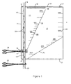
- a chamber 2 for separating fat from blood The chamber 2 has an inlet 5 and an outlet 6.
- the chamber 2 has a substantially rectangular shape and a pipe 4 extends along one edge 7 of the chamber 2.
- the chamber 2 has a slot 8 on the edge 7 exposing a portion 9 of the pipe 4.
- the remaining portion 18 of the pipe 4 between the inlet 5 and the outlet 6 is enclosed within the chamber 2 and has perforations 201.
- the pipe 4 may be located anywhere within the chamber 2 with opening 8 exposing a portion of the pipe 4.
- a sealing clamp 10 is mounted on the exposed portion 9 of the pipe 4.
- the chamber 2 is divided into two compartments 11 and 12 by a welded seam 14.
- the compartments 11 and 12 are in communication via a first channel 15 due to an interruption in the seam 14 and a second channel, in this embodiment provided by the portion 9 of the pipe 4 bridging the slot 8.
- a de-foamer 16 and an air escape valve 17 are located along the uppermost edge 19 of the chamber 2 when the chamber 2 is in an in use position.
- a volume scale 20 for each of the compartments 11 and 12 is incorporated into the plastic material of the chamber 2.
- a second sealing clamp 22 is mounted on a portion 23 of the pipe 4 outside the chamber 2 after the outlet 6.
- the chamber 2 and pipe 4 described in this embodiment are produced from a pliable transparent plastic material, although they are not limited to this particular material.
- pericardial suction blood from a surgery site is pumped to the inlet 5 of the pipe 4 and continues down through the pipe 4 until it reaches the clamp 10.
- barometric pressure forces blood and air from the wound out through perforations 201 in the portion 18 of the pipe 4.
- Blood collects in compartment 11 and the fat contained therein flows to the top of the blood under a normal process of separation. If the blood fills the compartment 11, it can flow over into compartment 12 via channel 15.
- the de-foamer 16 is activated in the event of foaming of blood in its vicinity. Seam 14 and an additional seam 31 promote the flow of blood towards the clamp 10 and the outlet 6 respectively when the chamber 2 is held in an in use position.
- the clamp 10 When the perfusionist is satisfied that a substantial portion of the fat has collected in a layer on top of the blood in compartment 11, the clamp 10 is opened and under normal barometric pressure, the blood flows from compartment 11 into compartment 12.
- the geometry of compartments 11 and 12 and their spatial orientation relative to one another is designed so that a final volume of blood containing the layer of fat which has collected on top of the blood in compartment 11 remains in compartment 11 after the transfer of the blood to compartment 12.
- This design feature of the chamber 2 reduces the need for careful visual monitoring of the transfer of blood from compartment 11 to compartment 12 by a perfusionist, improving the functionality of the chamber 2.
- the clamp 10 When substantially all of the blood from compartment 11 has transferred to compartment 12, the clamp 10 is reapplied to the exposed portion 9 of the pipe 4.
- the compartment 11 refills with inflowing blood from the surgery site.
- the separated fat layer remains adjacent the surface of the blood.
- Fat contained in the blood flowing into the compartment 11 again begins to float towards the surface of the blood stored in the compartment 11.
- the fat contained in the blood stored in compartment 12 also floats towards the top surface. There is no turbulence from incoming blood to disturb the process of separation in compartment 12 so further separation of fat and blood occurs efficiently.
- the second clamp 22 is opened after a predetermined time and blood flows from the compartment 12 into a venous reservoir (not shown) or directly back to the body of a patient.
- the perfusionist prevents the last portion of the blood which contains the layer of fat from leaving compartment 12 through the outlet 6.
- the scale 20 on the chamber 2 is used for this purpose in conjunction with visual monitoring by the perfusionist.
- chamber 2 provides the operator with a variety of uses for the chamber 2 when the chamber is manufactured from a pliable plastic material.
- the chamber 2 is rolled around the pipe 4. If an operator wishes to avail of the function of fat separation, the chamber 2 is uncoiled from the pipe 4 and mounted on a holder (not shown).
- the chamber 2 can be manufactured having a short pipe 4 which is connected, or cut in, to an existing pipe used for standard and commercially available machinery of heart lung technology.
- These pipe-to-pipe connectors are of standard design and commercially available.
- the inlet pipe 5 and outlet pipe 6 may have branched connectors for in and out coming pipes.
- the chamber 2 includes a recess (not shown) in or about edge 19 for receiving a spike for releasably securing the chamber 2 on the holder.
- the chamber 2 can be used as a standard blood pipe 4 with the chamber 2 remaining wrapped around the pipe 4 during use.
- the air valve 17 is in a closed position on delivery and must be opened if the fat separation function is needed. If a large volume of blood is being removed from the surgery site, it is possible to use the chamber 2 in an open system, allowing blood to flow through the system continuously provided the inlet 5 and outlet 6 are in direct communication.
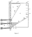
- FIG. 2 there is shown a chamber 2 substantially as described in Figure 1 .
- Reference numerals used to designate features of the chamber 2 of Figure 1 are used to designate identical features of the chamber 2 in Figures 2 to 6 , which illustrate similar embodiments of the chamber 2.
- an additional compartment 41 is shown having an integral filter 42 welded or glued to the plastic material of the compartment 41.
- a second recess 43 exposes an additional portion 44 of the pipe 4 and a third clamp 45 is mounted on this portion 44.
- the chamber 2 works in the same way as the chamber 2 of Figure 1 but including the additional step of blood in compartment 12 flowing into compartment 41 and contacting the absorbing material of the filter 42 prior to the blood flowing back to the venous reservoir or back into the patient's body.
- the filter 42 absorbs fat from the blood which has reached a partially solid state or fat which has an increased viscosity due to (1) cooling as a result of the blood being stored in the chamber 2 during the separation process and/or (2) cooling by a heat exchanger (not shown).
- This chamber 2 is also suitable for allowing through flow of blood by removing all the clamps 10, 22, 45, if high volume bleeding occurs at the surgery site.
- FIG. 4 shows a filter 42 welded or glued to an internal surface 51 of the chamber 2.
- the de-foamer 16 is shown adjacent the top edge 52 of the chamber 2.
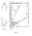
- FIGs 5 and 6 a second embodiment of filter 61 is shown which is free to move in the compartment 12 and without blood passing through the filter 61.
- the filter 61 can be fixed to either or both internal surfaces 62 of the chamber 2. It is also within the scope of the invention to envisage an additional absorbing filter located freely or fixed in the compartment 11.
- the blood contacts the filter 61, which is typically but not exclusively manufactured from cellulose or polyester fiber and fat particles adhere to the filter 61.
- This filter 61 further increases the separation of fat and blood already occurring due to flotation of fat to the surface of the stored blood.
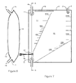
- Figures 7 and 8 show a third embodiment of chamber 2 having specially formed attachments 71 integrated into a side 74 of the chamber 2 for inlet pipe 72 and outlet pipe 73.
- a similar attachment 71 is used for the air escape valve 17.
- This construction removes the need for a pipe 4 extending within the chamber 2.
- a clamp 75 is mounted directly onto the chamber 2 on or about channel 13 in order to prevent blood from flowing between compartments 11 and 12. It will of course be appreciated that filters of the type described in relation to Figures 2 to 6 may be incorporated into the chamber 2 of this embodiment.
- Figures 9 and 10 show the chamber 2 of Figure 1 incorporating a heat exchanger 80.
- Figure 10 shows a heat exchanger 80 having a heat exchange chamber 81 fixed onto one side, of the chamber 2.
- the heat exchange chamber 81 has an inlet 82 and an outlet 83 and provides a pathway for a flow, preferably although not exclusively a reverse-flow (relative to the direction of flow of blood), cooling or heating medium which can be pumped through the heat exchange chamber 81.
- the cooling medium lowers the temperature of the blood towards approximately 5 °-10 °C.
- fat in the liquid form contained in the blood solidifies or has a higher viscosity, and is much easier to remove from the blood by contact with absorbing filters 42, 61 as described above.
- the blood temperature is maintained at 37 ° C or increased towards approximately 40 ° C in order to lower the viscosity of fat in liquid form which facilitates its separation from the blood medium.
- FIGS 11 and 12 show a different construction of heat exchanger 90 which is provided by a coil 92 fixed to one side of the chamber 2.
- the coil 92 has an inlet 93 and an outlet 94 which, in combination with the coil 92, provide a pathway for the temperature-controlling medium.
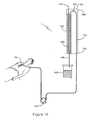
- Figure 13 and Figure 14 show an alternative construction of heat exchanger 100 provided by a piezoelectric element 101 mounted on one side of the chamber 2.
- the piezoelectric element 101 has a number of recesses 102 on one face 103.
- the recesses 102 extend from and are spaced angularly around a central point 104 which defines an opening into a bore 105.
- the bore 105 may be located anywhere along any of the recesses 102.
- the bore 105 extends through the piezoelectric element 101 and is connected to a vacuum pump (not shown).
- the bore 105 may extend and connect to the vacuum pump from other locations of the piezoelectric element 101.
- the piezoelectric element 101 is placed in contact with the chamber 2 and the vacuum pump generates a vacuum resulting in the chamber 2 and piezoelectric element 101 adhering to one another.
- the piezoelectric element 101 induces cooling of the blood flowing through the chamber 2 via an electrical circuit.
- a piezoelectric element 101 can be provided on both sides of the chamber 2.
- Figures 15 and 16 show another configuration of heat exchanger 110 provided by a double-sided coil 111.
- the double-sided coil 111 is connected via a port 112 allowing the cooling/heating medium to flow through the coil 111 on both sides of the chamber 2.
- the cooling/heating medium flows in through inlet 114 and up along one side of the coil 111.
- the medium passes through port 112 and flows down along the opposite side of the chamber 2 and out through outlet 115.
- Figures 17 and 18 illustrate another embodiment of heat exchanger 130.
- a heat exchange chamber 131 having an inlet 132 and an outlet 133 is located within the chamber 2. In use, the medium flows into the heat exchange chamber 131 through inlet 132 and is pumped up through the heat exchange chamber 131 contra to the flow of blood or in the same direction.
- FIG 19 illustrates an apparatus 1 having a heat exchanger 161 having an inlet 162 and an outlet 163 providing a flow path for a medium into, through and out of the heat exchanger 161.
- a separation chamber 164 having a blood inlet pipe 165 and a blood outlet pipe 166.
- the separation chamber 164 also includes an air escape valve 167 and has an absorbing filter 168 housed within the chamber 164.
- the blood outlet pipe 166 flows to a venous reservoir 169, the venous reservoir 169 being a part of commercially available heart and lung machines used for cardiac surgery. Alternatively, the blood with reduced fat may also be allowed to drain directly into the body of the patient (not shown).
- pericardial blood is pumped by a standard pump 153 from surgery site 151 to the separation chamber 164 via the blood inlet pipe 165.
- blood could be aspirated by the standard pump 153 or a vacuum source (not shown) through the separation chamber 164 for which mode of action the air escape valve 167 is omitted.
- a portion 152 of the blood inlet pipe 165 is contained within the heat exchanger 161 and blood flowing through this portion 152 is subject to cooling prior to entering the chamber 164 by the cooling medium flowing through the heat exchanger 161.
- the cooled blood has a temperature towards approximately 5 °-10 °C as it enters the chamber 164.
- the fat contained within the blood has solidified, or reached a level of high viscosity, and is absorbed by the filter 168, which preferably but not exclusively is formed from cellulose or polyester fiber.
- the fat-reduced blood returns to the venous reservoir 169.
- blood can flow continuously from the surgery site 151 through the apparatus without the need for clamps or other flow restrictors.
- the chamber 164 is produced from a pliable transparent plastic material, although they are not limited to this particular material.
- a chamber 164 manufactured from a rigid material is also within the scope of the invention.
- the heat exchanger 161 could have features similar to that described in any of the previous Figures 9 to 18 .
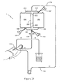
- Figure 20 shows an apparatus 1 having a pump 173 mounted on a pipe 174 between the surgery site 172 and a heat exchanger 175.
- the heat exchanger 175 is mounted on a portion of the pipe 174 leading into chamber 2.
- the chamber 2 in this embodiment is similar in construction and function to the chamber 2 described in Figure 1 .
- a commercially available filter 179 for through flow of blood such as (PALL LeukoGuard RS ® , PALL Medical, Portsmouth, England) is provided on a section of the pipe 174 leading away from the chamber 2.
- the pipe 174 is then connected to a venous reservoir 176 or is connected directly back to the body of the patient 177.
- blood is pumped from the surgery site 172 by a standard pump 173 to the heat exchanger 175 via the pipe 174.
- the heat exchanger 175 is used to reduce the temperature of the blood towards approximately 5°-10 °C.
- the chamber 2 includes a number of absorbing filters (not shown) which are preferably, but not exclusively manufactured from cellulose or polyester fiber. Fat in the pericardial suction blood solidifies or reaches a level of high viscosity at reduced temperatures and is absorbed by the filters. In addition, the blood and fat can be separated further in the chamber 2 as described in the in use description of Figure 1 .
- the commercial filter 179 removes any fat remaining in the blood after it passes through the chamber 2. The blood is then alternatively redirected to the venous reservoir 176 or back to the patient's body 177.
- FIG. 21 there is shown a chamber 181 comprising compartments 184 and 185 as separate units connected by pipes 182 and 183. It will of course be appreciated that a heat exchanger as previously discussed could also be applied to the apparatus 1 of this embodiment.
- the pipe 174 from the surgery site 172 branches into two separate pipes 202, 203 which enter a chamber 184 and 185 respectively.
- a clamp 187 blocks the pipe 203 entering chamber 185.
- Outlet pipes 188, 189 extend from the base of the compartments 184 and 185 respectively and these pipes merge together to form a single pipe 190.
- a second clamp 191 blocks the pipe 188 emerging from compartment 184 and a third clamp 192 blocks the pipe 190. In use, blood flows unimpeded into compartment 184 until it reaches clamp 191.
- the fat in the blood collecting in compartment 184 starts to float towards the surface of the blood.
- clamp 191 is opened and the blood flows through the outlet pipe 188 and up into the compartment 185.
- the fat which has collected adjacent the surface of the blood remains in the compartment 184.
- the clamp 191 is closed when the desired amount of blood has flown into the compartment 185.
- This blood is allowed to settle again in the compartment 185 in order to allow additional fat to float to the surface of the blood.
- clamp 192 is released and all the blood except the blood containing the separated fat is allowed to flow out of the compartment 185. This blood flows through filter 179 removing still further fat.
- filters can be located in both or either of the compartments 184 and 185.
- the two compartments 184 and 185 can be used separately.
- blood flows unimpeded into compartment 184 until it reaches clamp 191.
- clamp 187 is opened and moved to instead occlude inlet pipe 202.
- Additional blood now enters the opened inlet tube 203 and container 185.
- the fat in the blood collected in compartment 184 starts to float towards the surface of the blood without interference from turbulence of incoming blood.
- the lower fraction of blood in container 184 is emptied by first occluding the outlet pipe 189, by moving the clamp 192 to its new location 189, and opening the outlet pipe 188 by removing clamp 191.
- the top fraction of blood in container 184, holding a concentrated amount of fat, is prevented from reaching the patient by re-occluding outlet pipe 188 using clamp 191.
- the same procedure is carried out with compartment 185 after filling with further incoming blood being re-directed to again fill compartment 184.
- an apparatus 1 having a chamber 300 comprising compartments 301 and 302 and with an interconnecting conduit 303.
- the chamber 300 is substantially as described in Figure 1 with reference to chamber 2 but with a spatial arrangement of compartment 301 being above compartment 302.
- An inlet 304 directs blood via pipe 305 to collect in compartment 301 via perforations 306 identical to what is described for pipe 4, compartment 11, and perforations 201 in Figure 1 .
- the pipe 305 is here illustrated to have essentially a central location within chamber 300 but can be located along the edge of chamber 300 similar to what is described for pipe 4 of chamber 2 in Figure 1 .
- the chamber 300 has an opening 307 positioned within the space of compartment 301 created by an encircling welded seam 308 exposing a portion 309 of the pipe 305.
- a first sealing clamp 310 is mounted on the exposed portion 309 of the pipe 305 to block the pipe 305 in order for blood to collect in compartment 301.
- Air that collects in compartment 301 together with blood pumped from the patient's wound escapes from compartment 301 via a valve opening 311 that is positioned essentially along the top edge of compartment 301, similar to what is described for valve 17 in Figure 1 .
- the valve 311 could be connected by a separate pipe to the venous reservoir (not shown).
- the compartment 301 is in connection with compartment 302 via the conduit 303.
- the conduit 303 comprises a channel 312 at the bottom of compartment 301, an entrapped space 313 of compartment 301 created by two welded seams 314 that connects with the welded seam 308, perforation 315 of pipe 305, an extension 316 of pipe 305 into compartment 302, and perforation 317 of pipe 305.
- the spatial arrangement of the details 312, 313, 315, and 316 of conduit 303 create together a water-lock mechanism 320.
- the water-lock mechanism 320 is symmetrically arranged on both sides of the pipe 305 but can also be single-sided in the case the pipe 305 is located along the edge of the chamber 300, similar to what is described in Figure 1 .
- the conduit 303 has an opening 321, similar to 307, exposing a section 322 of the pipe 316.
- a second sealing clamp 325 is mounted on the exposed section 322 of the pipe 316 to open and close the conduit 303.
- Located at the top of the entrapped space 313 is a venting port 327 consisting of a pipe 328 inside compartment 301 in connection with the top of chamber 300.
- the pipe 328 could connect with the valve opening 311. It is of course appreciated that the port 327 and venting pipe 328 can have a path outside compartment 301.
- the venting port 327 of conduit 303 prevents a negative barometric pressure to build up within the water-lock mechanism 320 to prevent a portion of the blood that has accumulated in compartment 301 to fill over to compartment 302 when the sealing clamp 325 is released.
- Fat collects at the top surface of blood in compartment 301 and remains in compartment 301 together with the top portion of blood that is prevented to flow over into compartment 302.
- the flow rate by which fat-reduced blood fills over from compartment 301 to compartment 302 is controlled by the flow resistance of conduit 303, in particular but not limited to a narrowing within channel 312.
- a typical drainage time is about 30 seconds but can set to other time duration depending on use of the apparatus 1.
- the compartment 302 comprises an extension 316 of pipe 305 with one or more perforations 317, and pipe 305 emerges at the bottom of compartment 302 to form an outlet 330.
- a third sealing clamp 331 is mounted on the pipe 305 at outlet 330 of compartment 302 to control drainage of blood from the chamber 300 into the venous reservoir (not shown) or back into the patient's body.
- This chamber 300 is also suitable for allowing through flow of blood by removing all the clamps 310, 325, 331, if high volume bleeding occurs at the surgery site. It is well appreciated within the scope of the invention that the design of compartment 302 can be similar to what is described for compartment 301 comprising a second water-lock mechanism identical to the water-lock 320.
- the second water lock prevents the last portion of blood in compartment 302, containing a concentrated amount of fat that has accumulated at the top surface of blood, to reach the patient's body. It is also understood that additional compartments, identical to 301 and 302, can be connected in series to form a multi-compartment fat-separation chamber. It will further be appreciated that a fat-absorbing filter of the type described in relation to Figures 2 to 6 may be incorporated into the chamber 300 of this embodiment, that a heat exchanger as previously discussed could also be applied to the apparatus 1 of this embodiment, and that pipe connections 71 of Figures 7 and 8 could be used within this embodiment.
- the chamber 300 and pipe 305 described in this embodiment are produced from a pliable transparent plastic material, although they are not limited to this particular material.
- clamps described are not limited to manual actuation and could be operated mechanically, electrically, pneumatically or hydraulically.
Landscapes
- Health & Medical Sciences (AREA)
- Heart & Thoracic Surgery (AREA)
- Vascular Medicine (AREA)
- Biomedical Technology (AREA)
- Engineering & Computer Science (AREA)
- Anesthesiology (AREA)
- Cardiology (AREA)
- Hematology (AREA)
- Life Sciences & Earth Sciences (AREA)
- Animal Behavior & Ethology (AREA)
- General Health & Medical Sciences (AREA)
- Public Health (AREA)
- Veterinary Medicine (AREA)
- External Artificial Organs (AREA)
Applications Claiming Priority (3)
| Application Number | Priority Date | Filing Date | Title |
|---|---|---|---|
| SE0200381A SE523410C2 (sv) | 2002-02-08 | 2002-02-08 | Apparat för reducering av fettinnehåll i blod |
| SE0200381 | 2002-02-08 | ||
| PCT/SE2003/000178 WO2003066136A1 (en) | 2002-02-08 | 2003-02-03 | Apparatus for reducing fat content of blood |
Publications (2)
| Publication Number | Publication Date |
|---|---|
| EP1480694A1 EP1480694A1 (en) | 2004-12-01 |
| EP1480694B1 true EP1480694B1 (en) | 2010-07-14 |
Family
ID=20286911
Family Applications (1)
| Application Number | Title | Priority Date | Filing Date |
|---|---|---|---|
| EP03705585A Expired - Lifetime EP1480694B1 (en) | 2002-02-08 | 2003-02-03 | Apparatus for reducing fat content of blood |
Country Status (6)
| Country | Link |
|---|---|
| US (1) | US7914508B2 (enExample) |
| EP (1) | EP1480694B1 (enExample) |
| AT (1) | ATE473771T1 (enExample) |
| DE (1) | DE60333345D1 (enExample) |
| SE (1) | SE523410C2 (enExample) |
| WO (1) | WO2003066136A1 (enExample) |
Families Citing this family (13)
| Publication number | Priority date | Publication date | Assignee | Title |
|---|---|---|---|---|
| USD539899S1 (en) | 2004-10-14 | 2007-04-03 | Astra Tech Ab | Blood recovery unit |
| USD576274S1 (en) | 2006-04-26 | 2008-09-02 | Astra Tech Ab | Fat reducing blood bag |
| ITMI20080622A1 (it) * | 2008-04-09 | 2009-10-10 | Eurosets Srl | Cardiotomo con raccordi di entrata e di uscita del sangue posizionati per ottimizzare il funzionamento. |
| US8535241B2 (en) | 2011-10-13 | 2013-09-17 | Magnolia Medical Technologies, Inc. | Fluid diversion mechanism for bodily-fluid sampling |
| US9022950B2 (en) | 2012-05-30 | 2015-05-05 | Magnolia Medical Technologies, Inc. | Fluid diversion mechanism for bodily-fluid sampling |
| US9060724B2 (en) | 2012-05-30 | 2015-06-23 | Magnolia Medical Technologies, Inc. | Fluid diversion mechanism for bodily-fluid sampling |
| US9204864B2 (en) | 2012-08-01 | 2015-12-08 | Magnolia Medical Technologies, Inc. | Fluid diversion mechanism for bodily-fluid sampling |
| EP3906952A1 (en) | 2012-10-11 | 2021-11-10 | Magnolia Medical Technologies, Inc. | Systems and methods for delivering a fluid to a patient with reduced contamination |
| US10772548B2 (en) | 2012-12-04 | 2020-09-15 | Magnolia Medical Technologies, Inc. | Sterile bodily-fluid collection device and methods |
| IL286196B (en) | 2012-12-04 | 2022-09-01 | Magnolia Medical Technologies Inc | Sterile device and methods for collecting body fluids |
| EP3541284B1 (en) | 2016-11-18 | 2023-02-22 | Magnolia Medical Technologies, Inc. | Device for blood sample collection with reduced hemolysis |
| IL309638A (en) | 2017-06-09 | 2024-02-01 | Magnolia Medical Technologies Inc | Liquid control devices and methods for their use |
| IL273025B2 (en) | 2017-09-12 | 2024-12-01 | Magnolia Medical Technologies Inc | Fluid control devices and methods of using them |
Family Cites Families (18)
| Publication number | Priority date | Publication date | Assignee | Title |
|---|---|---|---|---|
| US3866608A (en) * | 1973-10-23 | 1975-02-18 | Sorenson Research Co | Aseptic suction collection system and method |
| US4775482A (en) * | 1985-05-28 | 1988-10-04 | Mederi Medical Systems, Inc. | Method for removing fat and for purifying and defoaming liquids |
| US5203778A (en) | 1986-02-18 | 1993-04-20 | Boehringer Laboratories | Process and apparatus for removal of insoluble fat from blood of a patient |
| US5133703A (en) * | 1986-02-18 | 1992-07-28 | Boehringer Laboratories | Process and apparatus for collecting blood of a patient for autotransfusion |
| SU1504219A1 (ru) | 1987-07-13 | 1989-08-30 | Таджикский политехнический институт | Устройство дл очистки сточных вод |
| US4994022A (en) * | 1989-02-02 | 1991-02-19 | Stryker Corporation | Blood conservation system |
| US5049146A (en) * | 1989-05-31 | 1991-09-17 | Baxter International, Inc. | Blood/gas separator and flow system |
| US5362406A (en) * | 1990-07-27 | 1994-11-08 | Pall Corporation | Leucocyte depleting filter device and method of use |
| US5318556A (en) * | 1993-04-09 | 1994-06-07 | Deknatel Technology Corporation | Fluid bag |
| US5540836A (en) * | 1994-06-16 | 1996-07-30 | Coyne; Thomas J. | Wastewater treatment system and method |
| US5634893A (en) | 1995-04-24 | 1997-06-03 | Haemonetics Corporation | Autotransfusion apparatus |
| US5573526A (en) * | 1995-05-08 | 1996-11-12 | Minntech Corporation | Soft shell reservoir |
| US5653888A (en) | 1995-11-02 | 1997-08-05 | Arbor Technologies, Inc. | Fluid filter assembly including gel removing barbs |
| US5827243A (en) * | 1996-11-29 | 1998-10-27 | Palestrant; Aubrey M. | Collapsible aspiration catheter |
| US5879624A (en) * | 1997-01-15 | 1999-03-09 | Boehringer Laboratories, Inc. | Method and apparatus for collecting and processing blood |
| US6337049B1 (en) * | 1998-08-28 | 2002-01-08 | Yehuda Tamari | Soft shell venous reservoir |
| MXPA03004139A (es) | 2000-11-09 | 2004-09-10 | Luca Kenneth Allan De | Extraccion de grasa. |
| US6695804B2 (en) | 2001-04-24 | 2004-02-24 | Charles Dennis Rugenstein | Device for removal of fatty debris from blood |
-
2002
- 2002-02-08 SE SE0200381A patent/SE523410C2/sv not_active IP Right Cessation
-
2003
- 2003-02-03 AT AT03705585T patent/ATE473771T1/de not_active IP Right Cessation
- 2003-02-03 EP EP03705585A patent/EP1480694B1/en not_active Expired - Lifetime
- 2003-02-03 DE DE60333345T patent/DE60333345D1/de not_active Expired - Lifetime
- 2003-02-03 WO PCT/SE2003/000178 patent/WO2003066136A1/en not_active Ceased
- 2003-02-03 US US10/503,603 patent/US7914508B2/en not_active Expired - Fee Related
Also Published As
| Publication number | Publication date |
|---|---|
| SE0200381L (sv) | 2003-08-09 |
| US20050131333A1 (en) | 2005-06-16 |
| SE523410C2 (sv) | 2004-04-13 |
| DE60333345D1 (enExample) | 2010-08-26 |
| WO2003066136A1 (en) | 2003-08-14 |
| ATE473771T1 (de) | 2010-07-15 |
| SE0200381D0 (sv) | 2002-02-08 |
| US7914508B2 (en) | 2011-03-29 |
| EP1480694A1 (en) | 2004-12-01 |
| AU2003206542A1 (en) | 2003-09-02 |
Similar Documents
| Publication | Publication Date | Title |
|---|---|---|
| EP1480694B1 (en) | Apparatus for reducing fat content of blood | |
| CA1044103A (en) | Cardiotomy reservoir | |
| EP0745397B1 (en) | Blood filter and extracorporeal circuit | |
| WO1995024255A1 (en) | A filtration device for removal of leukocytes | |
| JPH0447583B2 (enExample) | ||
| EP1982739B1 (en) | Extracorporeal circuit | |
| JPH11506701A (ja) | 心臓切開用リザーバと静脈用リザーバの結合リザーバ | |
| EA016521B1 (ru) | Аппарат высокой производительности для фильтрации биологических жидкостей | |
| JP5699008B2 (ja) | 血液浄化装置 | |
| WO2003026773A1 (en) | Filtration device and system for biological fluids and a method for filtering | |
| WO1994023664A1 (en) | Fluid bag | |
| AU2003206542B2 (en) | Apparatus for reducing fat content of blood | |
| EP0767682B1 (en) | A device for filtration and collection of blood | |
| JP2002511013A (ja) | 体液を濾過し脱気する装置、特に血液濾過器 | |
| US8337700B1 (en) | High capacity biological fluid filtration apparatus | |
| JPH07194678A (ja) | 血液濾過用使い捨て滅菌済み器具 | |
| JP4747422B2 (ja) | 血液回路自動脱気システム | |
| JPS6330442Y2 (enExample) | ||
| JP2000107282A5 (enExample) | ||
| JPS64940Y2 (enExample) | ||
| JPS6323100Y2 (enExample) | ||
| JP3705850B2 (ja) | 貯血槽 | |
| JPH03277370A (ja) | 血液成分分離装置 |
Legal Events
| Date | Code | Title | Description |
|---|---|---|---|
| PUAI | Public reference made under article 153(3) epc to a published international application that has entered the european phase |
Free format text: ORIGINAL CODE: 0009012 |
|
| 17P | Request for examination filed |
Effective date: 20040907 |
|
| AK | Designated contracting states |
Kind code of ref document: A1 Designated state(s): AT BE BG CH CY CZ DE DK EE ES FI FR GB GR HU IE IT LI LU MC NL PT SE SI SK TR |
|
| AX | Request for extension of the european patent |
Extension state: AL LT LV MK RO |
|
| 17Q | First examination report despatched |
Effective date: 20060602 |
|
| GRAP | Despatch of communication of intention to grant a patent |
Free format text: ORIGINAL CODE: EPIDOSNIGR1 |
|
| GRAS | Grant fee paid |
Free format text: ORIGINAL CODE: EPIDOSNIGR3 |
|
| RAP1 | Party data changed (applicant data changed or rights of an application transferred) |
Owner name: ESTR ENGSTROM SCIENTIFIC & TECHNICAL RESEARCH AKTI Owner name: POLYSTAN AS |
|
| GRAA | (expected) grant |
Free format text: ORIGINAL CODE: 0009210 |
|
| AK | Designated contracting states |
Kind code of ref document: B1 Designated state(s): AT BE BG CH CY CZ DE DK EE ES FI FR GB GR HU IE IT LI LU MC NL PT SE SI SK TR |
|
| REG | Reference to a national code |
Ref country code: GB Ref legal event code: FG4D |
|
| REG | Reference to a national code |
Ref country code: CH Ref legal event code: EP |
|
| REG | Reference to a national code |
Ref country code: IE Ref legal event code: FG4D |
|
| REF | Corresponds to: |
Ref document number: 60333345 Country of ref document: DE Date of ref document: 20100826 Kind code of ref document: P |
|
| REG | Reference to a national code |
Ref country code: NL Ref legal event code: T3 |
|
| REG | Reference to a national code |
Ref country code: SE Ref legal event code: TRGR |
|
| REG | Reference to a national code |
Ref country code: CH Ref legal event code: NV Representative=s name: OFFICE ERNEST T. FREYLINGER S.A. |
|
| PG25 | Lapsed in a contracting state [announced via postgrant information from national office to epo] |
Ref country code: FI Free format text: LAPSE BECAUSE OF FAILURE TO SUBMIT A TRANSLATION OF THE DESCRIPTION OR TO PAY THE FEE WITHIN THE PRESCRIBED TIME-LIMIT Effective date: 20100714 Ref country code: AT Free format text: LAPSE BECAUSE OF FAILURE TO SUBMIT A TRANSLATION OF THE DESCRIPTION OR TO PAY THE FEE WITHIN THE PRESCRIBED TIME-LIMIT Effective date: 20100714 |
|
| PG25 | Lapsed in a contracting state [announced via postgrant information from national office to epo] |
Ref country code: PT Free format text: LAPSE BECAUSE OF FAILURE TO SUBMIT A TRANSLATION OF THE DESCRIPTION OR TO PAY THE FEE WITHIN THE PRESCRIBED TIME-LIMIT Effective date: 20101115 Ref country code: SI Free format text: LAPSE BECAUSE OF FAILURE TO SUBMIT A TRANSLATION OF THE DESCRIPTION OR TO PAY THE FEE WITHIN THE PRESCRIBED TIME-LIMIT Effective date: 20100714 Ref country code: CY Free format text: LAPSE BECAUSE OF FAILURE TO SUBMIT A TRANSLATION OF THE DESCRIPTION OR TO PAY THE FEE WITHIN THE PRESCRIBED TIME-LIMIT Effective date: 20100714 Ref country code: BG Free format text: LAPSE BECAUSE OF FAILURE TO SUBMIT A TRANSLATION OF THE DESCRIPTION OR TO PAY THE FEE WITHIN THE PRESCRIBED TIME-LIMIT Effective date: 20101014 |
|
| PG25 | Lapsed in a contracting state [announced via postgrant information from national office to epo] |
Ref country code: BE Free format text: LAPSE BECAUSE OF FAILURE TO SUBMIT A TRANSLATION OF THE DESCRIPTION OR TO PAY THE FEE WITHIN THE PRESCRIBED TIME-LIMIT Effective date: 20100714 Ref country code: GR Free format text: LAPSE BECAUSE OF FAILURE TO SUBMIT A TRANSLATION OF THE DESCRIPTION OR TO PAY THE FEE WITHIN THE PRESCRIBED TIME-LIMIT Effective date: 20101015 |
|
| PG25 | Lapsed in a contracting state [announced via postgrant information from national office to epo] |
Ref country code: DK Free format text: LAPSE BECAUSE OF FAILURE TO SUBMIT A TRANSLATION OF THE DESCRIPTION OR TO PAY THE FEE WITHIN THE PRESCRIBED TIME-LIMIT Effective date: 20100714 |
|
| PLBE | No opposition filed within time limit |
Free format text: ORIGINAL CODE: 0009261 |
|
| STAA | Information on the status of an ep patent application or granted ep patent |
Free format text: STATUS: NO OPPOSITION FILED WITHIN TIME LIMIT |
|
| PG25 | Lapsed in a contracting state [announced via postgrant information from national office to epo] |
Ref country code: IT Free format text: LAPSE BECAUSE OF FAILURE TO SUBMIT A TRANSLATION OF THE DESCRIPTION OR TO PAY THE FEE WITHIN THE PRESCRIBED TIME-LIMIT Effective date: 20100714 Ref country code: EE Free format text: LAPSE BECAUSE OF FAILURE TO SUBMIT A TRANSLATION OF THE DESCRIPTION OR TO PAY THE FEE WITHIN THE PRESCRIBED TIME-LIMIT Effective date: 20100714 Ref country code: SK Free format text: LAPSE BECAUSE OF FAILURE TO SUBMIT A TRANSLATION OF THE DESCRIPTION OR TO PAY THE FEE WITHIN THE PRESCRIBED TIME-LIMIT Effective date: 20100714 Ref country code: CZ Free format text: LAPSE BECAUSE OF FAILURE TO SUBMIT A TRANSLATION OF THE DESCRIPTION OR TO PAY THE FEE WITHIN THE PRESCRIBED TIME-LIMIT Effective date: 20100714 |
|
| 26N | No opposition filed |
Effective date: 20110415 |
|
| PG25 | Lapsed in a contracting state [announced via postgrant information from national office to epo] |
Ref country code: ES Free format text: LAPSE BECAUSE OF FAILURE TO SUBMIT A TRANSLATION OF THE DESCRIPTION OR TO PAY THE FEE WITHIN THE PRESCRIBED TIME-LIMIT Effective date: 20101025 |
|
| REG | Reference to a national code |
Ref country code: DE Ref legal event code: R097 Ref document number: 60333345 Country of ref document: DE Effective date: 20110415 |
|
| REG | Reference to a national code |
Ref country code: NL Ref legal event code: V1 Effective date: 20110901 |
|
| PG25 | Lapsed in a contracting state [announced via postgrant information from national office to epo] |
Ref country code: MC Free format text: LAPSE BECAUSE OF NON-PAYMENT OF DUE FEES Effective date: 20110228 |
|
| REG | Reference to a national code |
Ref country code: CH Ref legal event code: PL |
|
| REG | Reference to a national code |
Ref country code: SE Ref legal event code: EUG |
|
| PG25 | Lapsed in a contracting state [announced via postgrant information from national office to epo] |
Ref country code: CH Free format text: LAPSE BECAUSE OF NON-PAYMENT OF DUE FEES Effective date: 20110228 Ref country code: LI Free format text: LAPSE BECAUSE OF NON-PAYMENT OF DUE FEES Effective date: 20110228 |
|
| REG | Reference to a national code |
Ref country code: IE Ref legal event code: MM4A |
|
| PG25 | Lapsed in a contracting state [announced via postgrant information from national office to epo] |
Ref country code: NL Free format text: LAPSE BECAUSE OF NON-PAYMENT OF DUE FEES Effective date: 20110901 |
|
| PG25 | Lapsed in a contracting state [announced via postgrant information from national office to epo] |
Ref country code: IE Free format text: LAPSE BECAUSE OF NON-PAYMENT OF DUE FEES Effective date: 20110203 |
|
| PGFP | Annual fee paid to national office [announced via postgrant information from national office to epo] |
Ref country code: FR Payment date: 20120312 Year of fee payment: 10 |
|
| PGFP | Annual fee paid to national office [announced via postgrant information from national office to epo] |
Ref country code: DE Payment date: 20120305 Year of fee payment: 10 |
|
| PGFP | Annual fee paid to national office [announced via postgrant information from national office to epo] |
Ref country code: GB Payment date: 20120306 Year of fee payment: 10 |
|
| PG25 | Lapsed in a contracting state [announced via postgrant information from national office to epo] |
Ref country code: SE Free format text: LAPSE BECAUSE OF NON-PAYMENT OF DUE FEES Effective date: 20110204 |
|
| PG25 | Lapsed in a contracting state [announced via postgrant information from national office to epo] |
Ref country code: LU Free format text: LAPSE BECAUSE OF NON-PAYMENT OF DUE FEES Effective date: 20110203 |
|
| PG25 | Lapsed in a contracting state [announced via postgrant information from national office to epo] |
Ref country code: TR Free format text: LAPSE BECAUSE OF FAILURE TO SUBMIT A TRANSLATION OF THE DESCRIPTION OR TO PAY THE FEE WITHIN THE PRESCRIBED TIME-LIMIT Effective date: 20100714 |
|
| GBPC | Gb: european patent ceased through non-payment of renewal fee |
Effective date: 20130203 |
|
| PG25 | Lapsed in a contracting state [announced via postgrant information from national office to epo] |
Ref country code: HU Free format text: LAPSE BECAUSE OF FAILURE TO SUBMIT A TRANSLATION OF THE DESCRIPTION OR TO PAY THE FEE WITHIN THE PRESCRIBED TIME-LIMIT Effective date: 20100714 |
|
| REG | Reference to a national code |
Ref country code: FR Ref legal event code: ST Effective date: 20131031 |
|
| REG | Reference to a national code |
Ref country code: DE Ref legal event code: R119 Ref document number: 60333345 Country of ref document: DE Effective date: 20130903 |
|
| PG25 | Lapsed in a contracting state [announced via postgrant information from national office to epo] |
Ref country code: GB Free format text: LAPSE BECAUSE OF NON-PAYMENT OF DUE FEES Effective date: 20130203 Ref country code: DE Free format text: LAPSE BECAUSE OF NON-PAYMENT OF DUE FEES Effective date: 20130903 Ref country code: FR Free format text: LAPSE BECAUSE OF NON-PAYMENT OF DUE FEES Effective date: 20130228 |