EP1479967A2 - Systeme de montage pour appareils d'éclairage - Google Patents
Systeme de montage pour appareils d'éclairage Download PDFInfo
- Publication number
- EP1479967A2 EP1479967A2 EP04011709A EP04011709A EP1479967A2 EP 1479967 A2 EP1479967 A2 EP 1479967A2 EP 04011709 A EP04011709 A EP 04011709A EP 04011709 A EP04011709 A EP 04011709A EP 1479967 A2 EP1479967 A2 EP 1479967A2
- Authority
- EP
- European Patent Office
- Prior art keywords
- ceiling panel
- opening
- fixture
- fixture box
- ceiling
- Prior art date
- Legal status (The legal status is an assumption and is not a legal conclusion. Google has not performed a legal analysis and makes no representation as to the accuracy of the status listed.)
- Withdrawn
Links
Images


Classifications
-
- F—MECHANICAL ENGINEERING; LIGHTING; HEATING; WEAPONS; BLASTING
- F24—HEATING; RANGES; VENTILATING
- F24F—AIR-CONDITIONING; AIR-HUMIDIFICATION; VENTILATION; USE OF AIR CURRENTS FOR SCREENING
- F24F13/00—Details common to, or for air-conditioning, air-humidification, ventilation or use of air currents for screening
- F24F13/02—Ducting arrangements
- F24F13/06—Outlets for directing or distributing air into rooms or spaces, e.g. ceiling air diffuser
- F24F13/078—Outlets for directing or distributing air into rooms or spaces, e.g. ceiling air diffuser combined with lighting fixtures
-
- E—FIXED CONSTRUCTIONS
- E04—BUILDING
- E04B—GENERAL BUILDING CONSTRUCTIONS; WALLS, e.g. PARTITIONS; ROOFS; FLOORS; CEILINGS; INSULATION OR OTHER PROTECTION OF BUILDINGS
- E04B9/00—Ceilings; Construction of ceilings, e.g. false ceilings; Ceiling construction with regard to insulation
- E04B9/02—Ceilings; Construction of ceilings, e.g. false ceilings; Ceiling construction with regard to insulation having means for ventilation or vapour discharge
-
- E—FIXED CONSTRUCTIONS
- E04—BUILDING
- E04B—GENERAL BUILDING CONSTRUCTIONS; WALLS, e.g. PARTITIONS; ROOFS; FLOORS; CEILINGS; INSULATION OR OTHER PROTECTION OF BUILDINGS
- E04B9/00—Ceilings; Construction of ceilings, e.g. false ceilings; Ceiling construction with regard to insulation
- E04B9/32—Translucent ceilings, i.e. permitting both the transmission and diffusion of light
-
- F—MECHANICAL ENGINEERING; LIGHTING; HEATING; WEAPONS; BLASTING
- F21—LIGHTING
- F21S—NON-PORTABLE LIGHTING DEVICES; SYSTEMS THEREOF; VEHICLE LIGHTING DEVICES SPECIALLY ADAPTED FOR VEHICLE EXTERIORS
- F21S8/00—Lighting devices intended for fixed installation
- F21S8/02—Lighting devices intended for fixed installation of recess-mounted type, e.g. downlighters
- F21S8/026—Lighting devices intended for fixed installation of recess-mounted type, e.g. downlighters intended to be recessed in a ceiling or like overhead structure, e.g. suspended ceiling
-
- F—MECHANICAL ENGINEERING; LIGHTING; HEATING; WEAPONS; BLASTING
- F21—LIGHTING
- F21V—FUNCTIONAL FEATURES OR DETAILS OF LIGHTING DEVICES OR SYSTEMS THEREOF; STRUCTURAL COMBINATIONS OF LIGHTING DEVICES WITH OTHER ARTICLES, NOT OTHERWISE PROVIDED FOR
- F21V21/00—Supporting, suspending, or attaching arrangements for lighting devices; Hand grips
- F21V21/02—Wall, ceiling, or floor bases; Fixing pendants or arms to the bases
- F21V21/04—Recessed bases
-
- A—HUMAN NECESSITIES
- A62—LIFE-SAVING; FIRE-FIGHTING
- A62C—FIRE-FIGHTING
- A62C35/00—Permanently-installed equipment
- A62C35/58—Pipe-line systems
- A62C35/68—Details, e.g. of pipes or valve systems
-
- F—MECHANICAL ENGINEERING; LIGHTING; HEATING; WEAPONS; BLASTING
- F21—LIGHTING
- F21Y—INDEXING SCHEME ASSOCIATED WITH SUBCLASSES F21K, F21L, F21S and F21V, RELATING TO THE FORM OR THE KIND OF THE LIGHT SOURCES OR OF THE COLOUR OF THE LIGHT EMITTED
- F21Y2103/00—Elongate light sources, e.g. fluorescent tubes
Definitions
- the present invention concerns a mounting system for at least one fixture, including a ceiling panel with a top side and an underside which is provided with a covering, and where in the ceiling panel there is made a preferably rectangular, elongated opening with a number of side edges, and at least one fixture box which is provided with at least one open side.
- Fixture boxes with flanges extending down under the ceiling panel while getting hold of the underside of the ceiling panel simultaneously with the fixture box at the top side of the ceiling plate being provided with clamping abutments are visible and project down into the room. Therefore, they have an unwanted visual effect and they will not be relevant in buildings where unobtrusive design of the ceiling lighting is desired.
- fixture boxes that are fastened at the underside of the ceiling panel with screws or the like through contact surfaces, after which felt is used for covering the contact faces, and where irregularities are filled up subsequently.
- the open side of the fixture box is connected with the top side of the ceiling panel so that the fixture box lies on the top side of the ceiling panel, implying that no parts of the fixture box are protruding down below the underside of the ceiling panel, and that the fixture box is not fastened with screws or the like in order to stay in the desired position.
- the ceiling panel is not perforated at the underside when the fixture box is mounted.
- the mounting process is thereby simplified since the electrician can install the electric installations in the interspace between the ceiling and the suspended ceiling, after which the carpenter can put up the ceiling panels, and the underside of the ceiling panels can be surface treated, after which the electrician can mount and connect the fixture box. In this way, the carpenter and the electrician will not work at the same place at the same time.
- the ceiling panel in which a fixture box is to be mounted is provided with an elongated opening in which the fixture box is to be placed.
- this elongated opening is prefabricated so that the carpenter only has to know where a ceiling panel with an opening is to be fitted. This implies that the carpenter does not have to cut out the openings in a standard ceiling panel, and that openings in the ceiling panels become more uniform.
- the fixture box For easy fitting the fixture box, it is designed so that it has a height which is less than the width of the opening, and that the open side of the fixture box has a width at least corresponding to the width of the opening in the ceiling panel.
- the fixture box can be inserted in the opening by turning it 90° to one side.
- the fixture box is turned 90° back and may be disposed with the open side down against the top side of the ceiling panel.
- the open side of the fixture box has a width at least corresponding to the width of the opening in the ceiling panel, the fixture box will remain lying at the top side of the ceiling panel.
- the width of the open side of the fixture box is greater than the width of the opening in the ceiling panel, whereby it is possible to place the fixture box loosely at the top side of the ceiling panel, so that the fixture box is only connected to electric/mechanical connections or piping.
- the fixture box In order to retain the fixture box to the opening in the ceiling panel, the fixture box is provided with contact members at opposite long sides of the open side of the fixture box, and which contact members are designed as sockets that bear against the top side and the side edges of the opening in the ceiling panel.
- contact members have an angular part that bears against the top side of the ceiling panel and a socket part that extends down with a length into the opening and bears against a part of the side edges of the opening in the ceiling panel.
- a fixture panel with this type of contact members will be secured in the opening and cannot be laterally displaced, however, it will not be possible to displace the fixture box longitudinally.
- these contact members can be designed as angles that originate from the long sides of the fixture box and in over the ceiling panel, and be designed with downwards directed projections which due to the weight of the fixture box and the fixture are bearing against the top side of the ceiling panel, whereby the fixture box is retained.
- the opening in the ceiling panel has greater length than the fixture box. This implies that there is access to the interspace between the ceiling and the top side of the ceiling panel.
- the access can be used for connecting the fixture box to the electric network, to air ducts and/or piping.
- the mounting system includes a number of blank-off plates which may be disposed either releasably connected to the fixture boxes, or designed with a width which is greater than the width of the opening in the ceiling panel, so that they, like the fixture boxes, can be disposed at the top side of the ceiling panel.
- the lower edge of the blank-off plate is mounted in the opening in such a way that it lies at the same level as the lower edge of the fixture box.
- the blank-off plates are only used as screen plates that cover the remaining part of the opening in the ceiling panel.
- the blank-off plates are adapted for mounting measuring/sensor means, signal emitters, emergency lighting or sprinklers, where:
- the blank-off plates are designed with different shape that may constitute a uniform transition between different fixture members.
- the ceiling panels can be mounted staggered so that one elongated opening is formed in the room. In that way, e.g. a number of fixture boxes with different functions may be mounted.
- the present invention has been described used for mounting fixtures in a suspended ceiling.
- These fixtures can be of different kinds, so that said fixture boxes are arranged for mounting lighting, air-conditioning, ventilation and/or sensors, where the fixture boxes:
- the at least one open side of the fixture box can be designed so that it appears as partly open, e.g. it may be partly covered with a grating element, a guide plate, screen or the like.
- a light fixture is mounted in a suspended ceiling by means of the present invention and consists of the following steps:
- the ceiling panel is made of a number of plate elements which are joined.
- a joining of a number of plate elements will furthermore imply that the carrying capacity of the ceiling panel is increased considerably, and that there is a considerable reduction of the risk that the ceiling panel cracks/splits during transport from the factory to the site of mounting and in connection with the workmen's handling of the ceiling panel.
- the ceiling panel is made as a sandwich construction where upon the lowermost ceiling panel there is provided one or more ceiling panels.
- the dimension of these further ceiling panels may vary from being of the same dimension as the lower ceiling panel to having a dimension that only just encircles the opening.
- the ceiling panel has been reinforced with one or more panel parts which are connected with the side edges of the opening in an upright position so that assembling of panel parts and the ceiling panel occurs in the area around the opening.
- An upright panel part along the side edges of the opening will strengthen the ceiling panel, since the moment of inertia of the ceiling panel is considerably increased.
- the joint between the upright panel part and ceiling panel can be hidden behind a covering which is applied a peripheral edge of the opening.
- the ceiling panel is made of one thick plate element which is made with a thickness corresponding to the desired spacing between the underside of the fixture box and the underside of the ceiling panel.
- the joining between the panel part and the ceiling panel, or between the ceiling panels, can be performed by means of gluing, either as direct gluing or by means of double-adhesive tape.
- the individual ceiling panels will typically be joined first and the openings will be cut out subsequently, so that the side edges of the openings become as uniform as possible.
- the openings can be cut out at first, after which the ceiling panels are joined.
- the side edges of the opening in the ceiling panel are provided with a side covering of the same nature as the covering at the underside of the ceiling panel. This implies that no unwanted colour differences and edges will appear when the suspended ceiling is painted, since the side covering and the covering at the underside of the ceiling panel are having the same absorbing capacity.
- the side covering of the opening is a part of the covering at the underside of the ceiling panel which has been bent up into the opening and fastened at least along the side edges of the opening. This puts further demands on the production process of the ceiling panels, since the cutting of the opening must not destroy the covering at the underside of the ceiling panel.
- the ceiling panel may e.g. be made with openings in the pressing/moulding process, after which covering on the side faces of the ceiling panel is mounted, and the covering around the opening can be cut, bent up into the opening and fastened along at least the side edges of the opening.
- the ceiling panels can be made with two plies of covering at the underside of the ceiling panel, where the first ply of covering is mounted before making the opening in the ceiling panel, whereas the second ply of covering is mounted after cutting the opening, whereby the covering around the opening can be cut, bent up into the opening and fastened along at least the side edges of the opening.
- the opening By providing the peripheral edge with a bent covering which is fastened to the underside of the ceiling panel and which extends a length up into the opening, the opening will furthermore be protected against deformation through impact and the like, e.g. when fixture box is installed.
- the covering can cover up through the opening, so that all long side edges in the opening is coated with covering. If the covering is provided with a reflecting surface, the covered long side edges in the opening can function as a part of the reflecting screen of the fixture, whereby the light intensity and the scattering of light can be changed and/or increased.
- the covering at the underside of the ceiling panel, the side covering along the side edges of the opening and the edge covering along the peripheral edge is made of one or more of the following materials: paper, cardboard, plastic film and metal film.
- the ceiling panels are made of a gypsum material and the covering of paper.
- the mounting system furthermore includes a bridge member which is adapted for retaining the fixture down against the top side of the ceiling panel.
- This bridge member is mounted displacing in the suspension of the ceiling panels before mounting the fixture box.
- the bridge member is displaced across the top side of the fixture box so that it cannot be lifted out of the opening.
- the bridge member may be designed so that it approximately has a clearance fitting with the height of the fixture box, so that there are only a couple of millimetres between the underside of the bridge element and the top side of the fixture box. This implies that there is room for the ceiling panel, suspension and bridge member to work a bit, depending on temperature and general settling of the building without the fixture box being wedged. This clearance furthermore entails that the bridge member may easily be displaced laterally across the fixture box.
- One or more bridge members are to be placed for each fixture box. However, it must be possible to reach up through the opening when the fixture box has been positioned, and to displace the bridge member across the fixture box.
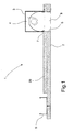
- a mounting system 1 for mounting a fixture box 3 in a suspended ceiling which includes a suspension rail 5 and a ceiling panel 2 designed with elongated openings 8.
- the ceiling panel 2 is reinforced with a ceiling panel 20.
- the elongated opening 8 has been made through both ceiling panels 2, 20.
- the fixture box 3 with fixture 4 is mounted in the opening 8 where the contact members 7 of the fixture box 3 bear against side edges of the opening 8.
- the fixture box 3 has a height which is less than the width of the opening 8 so that it is possible to insert fixture box 3 through opening 8.
- On the peripheral edge 8 in ceiling panel 2 there is fitted a bent covering 6 that protects the peripheral edge.
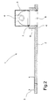
- a mounting system 1 for mounting a fixture box 3 in a suspended ceiling that includes a suspension rail 5 and a ceiling 2 which is designed with elongated openings 8.
- the ceiling panel 2 around the opening 8 is reinforced with an upright plate part 9 which, apart from increasing the strength of the ceiling panel 2, elevates the fixture box 3 up into the suspended ceiling.
- the upright plate part 9 is joined with the ceiling panel 2 at the peripheral edge of the opening 8, but the joining is hidden behind a bent covering 6.
- the contact members 7 of the fixture box 3 are bearing against an edge part of the upright plate part 9.
- a fixture box 10 adapted for mounting other types of fixtures (not shown).
- an opening 11 At the top of fixture 10 is designed an opening 11 that may be used for e.g. connection to air ducts, pipes or flexible hoses.
- Fig. 4 On Fig. 4 is shown a side view of a fixture box 3 which is mounted in an elongated opening 8. In connection with the fixture 4 is mounted a grating 12 and a blank-off plate 13 that covers the part of the opening 8 which is not covered by the light fixture 4.
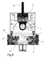
- a fixture box 3 in which is fitted a light fixture 4 connected to the network via wire 16.
- the contact members 7 of the fixture box 3 includes an angular par 22 and a socket member 21, where socket member 21 engages the peripheral edge of the opening 8, preventing lateral displacement of fixture box 3 while angular part 22 bears against the top side of the ceiling panel 2, preventing fixture box 3 from falling through opening 8.
- a fixture box 3 with fixture 4, grating 12 and blank-off plate 13 which is provided with an aperture 15 for e.g. a sprinkler nozzle (not shown).
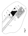
- Fig. 7 On Fig. 7 is shown how the fixture box (not shown) is mounted in the opening 8 in the ceiling panel 2.
- the socket part 21 of the fixture box contact members 7 bears against the peripheral edge of the opening 8.
- Blank-off plate 13 is to cover the part of opening 8 that fixture 4 does not cover.
- a fixture 4 fully mounted in ceiling panel 2.
- Blank-off plate 13 is mounted in opening 8 and covers the part of opening 8 which fixture 4 does not cover.
- a sprinkler nozzle 14 In connection with blank-off plate 13 is mounted a sprinkler nozzle 14.
- a bridge element 30 that at each end is connected displacing in suspension rails 5.
- the bridge element 30 is disposed across the top side of the fixture box 3 so that the fixture box 3 is held down against the top side of the ceiling panel 2 and in place in the opening 8.
Landscapes
- Engineering & Computer Science (AREA)
- General Engineering & Computer Science (AREA)
- Architecture (AREA)
- Chemical & Material Sciences (AREA)
- Combustion & Propulsion (AREA)
- Mechanical Engineering (AREA)
- Physics & Mathematics (AREA)
- Electromagnetism (AREA)
- Civil Engineering (AREA)
- Structural Engineering (AREA)
- Residential Or Office Buildings (AREA)
- Non-Portable Lighting Devices Or Systems Thereof (AREA)
Applications Claiming Priority (2)
| Application Number | Priority Date | Filing Date | Title |
|---|---|---|---|
| DKPA200300767 | 2003-05-21 | ||
| DK200300767 | 2003-05-21 |
Publications (2)
| Publication Number | Publication Date |
|---|---|
| EP1479967A2 true EP1479967A2 (fr) | 2004-11-24 |
| EP1479967A3 EP1479967A3 (fr) | 2005-12-21 |
Family
ID=33040864
Family Applications (1)
| Application Number | Title | Priority Date | Filing Date |
|---|---|---|---|
| EP04011709A Withdrawn EP1479967A3 (fr) | 2003-05-21 | 2004-05-18 | Système de montage pour appareils d'éclairage |
Country Status (1)
| Country | Link |
|---|---|
| EP (1) | EP1479967A3 (fr) |
Cited By (3)
| Publication number | Priority date | Publication date | Assignee | Title |
|---|---|---|---|---|
| WO2010078741A1 (fr) * | 2008-12-29 | 2010-07-15 | Xu Jianguang | Structure décorative de plafond de bâtiment |
| EP2306080A1 (fr) * | 2008-06-27 | 2011-04-06 | Optoworld Co., Ltd. | Dispositif de support de modules électroluminescents |
| RU179326U1 (ru) * | 2017-10-17 | 2018-05-08 | Закрытое акционерное общество "Производственное объединение "Спецавтоматика" | Устройство монтажное для спринклерного оросителя |
Citations (5)
| Publication number | Priority date | Publication date | Assignee | Title |
|---|---|---|---|---|
| US2376715A (en) * | 1940-06-27 | 1945-05-22 | Miller Co | Ceiling |
| US4431151A (en) * | 1981-07-21 | 1984-02-14 | Robert L. Fournier | Fixture supporting clip |
| US4729074A (en) * | 1986-12-11 | 1988-03-01 | Steadman Earl J | Ceiling frame for a lighting fixture |
| EP0805313A2 (fr) * | 1996-04-30 | 1997-11-05 | Schako Metallwarenfabrik Ferdinand Schad Kg | Sortie d'air |
| DE10124000A1 (de) * | 2001-05-17 | 2002-12-05 | Spectral Ges Fuer Lichttechnik | Decke eines Raumes in Bauwerken |
-
2004
- 2004-05-18 EP EP04011709A patent/EP1479967A3/fr not_active Withdrawn
Patent Citations (5)
| Publication number | Priority date | Publication date | Assignee | Title |
|---|---|---|---|---|
| US2376715A (en) * | 1940-06-27 | 1945-05-22 | Miller Co | Ceiling |
| US4431151A (en) * | 1981-07-21 | 1984-02-14 | Robert L. Fournier | Fixture supporting clip |
| US4729074A (en) * | 1986-12-11 | 1988-03-01 | Steadman Earl J | Ceiling frame for a lighting fixture |
| EP0805313A2 (fr) * | 1996-04-30 | 1997-11-05 | Schako Metallwarenfabrik Ferdinand Schad Kg | Sortie d'air |
| DE10124000A1 (de) * | 2001-05-17 | 2002-12-05 | Spectral Ges Fuer Lichttechnik | Decke eines Raumes in Bauwerken |
Cited By (4)
| Publication number | Priority date | Publication date | Assignee | Title |
|---|---|---|---|---|
| EP2306080A1 (fr) * | 2008-06-27 | 2011-04-06 | Optoworld Co., Ltd. | Dispositif de support de modules électroluminescents |
| EP2306080A4 (fr) * | 2008-06-27 | 2011-10-05 | Optoworld Co Ltd | Dispositif de support de modules électroluminescents |
| WO2010078741A1 (fr) * | 2008-12-29 | 2010-07-15 | Xu Jianguang | Structure décorative de plafond de bâtiment |
| RU179326U1 (ru) * | 2017-10-17 | 2018-05-08 | Закрытое акционерное общество "Производственное объединение "Спецавтоматика" | Устройство монтажное для спринклерного оросителя |
Also Published As
| Publication number | Publication date |
|---|---|
| EP1479967A3 (fr) | 2005-12-21 |
Similar Documents
| Publication | Publication Date | Title |
|---|---|---|
| US6226939B1 (en) | Downlighter cover | |
| CA1048221A (fr) | Plafond a coffrage | |
| EP0908668A3 (fr) | Boítier résistant au feu pour luminaire | |
| EP2180240B1 (fr) | Anneau pour aperture du lampe | |
| US20030106276A1 (en) | Ceiling tile support system and method | |
| CN102906357A (zh) | 用于干墙施工的可闭合检查口 | |
| US5649393A (en) | Domed ceiling structure | |
| EP1479967A2 (fr) | Systeme de montage pour appareils d'éclairage | |
| US7096633B1 (en) | Method of hanging a false cloth ceiling | |
| US20090107083A1 (en) | Multicategory Collection of Ceiling/Wall Devices With Familial Appearances | |
| CA2313121C (fr) | Boitier amovible d'avertisseur d'incendie | |
| US4427171A (en) | Mounting bracket for use in installing beam-like channel members under horizontal surfaces, in particular ceilings | |
| FR2762630B1 (fr) | Grille pour la construction d'un faux plafond suspendu | |
| US7325948B2 (en) | Recessed light fixture | |
| CA2471528A1 (fr) | Dispositif et methode d'encastrement de grilles a conduits d'air, de plaques de commandes electriques, de plaques de prises de courant, de luminaires et d'autres couvercles d'ouvertures de cloison seche sur des surfaces pourvues de baguettes pour cloison seche | |
| KR20200142197A (ko) | 조립식 블록형 실내 인테리어 마감재 | |
| JPH05182508A (ja) | 天井に於ける照明装置 | |
| US8582120B2 (en) | Measurement device and method | |
| JPH0447288Y2 (fr) | ||
| DE29821295U1 (de) | Unterdecke für Brandschutzzwecke | |
| JP3098821B2 (ja) | システム天井 | |
| JP2008184866A (ja) | 地下施設用天井構造 | |
| JPH1037447A (ja) | 天井裏点検口の構造 | |
| NO345404B1 (en) | Mounting bracket and method for mounting an object to a connection box | |
| JPH05179748A (ja) | 天井骨組用横架材 |
Legal Events
| Date | Code | Title | Description |
|---|---|---|---|
| PUAI | Public reference made under article 153(3) epc to a published international application that has entered the european phase |
Free format text: ORIGINAL CODE: 0009012 |
|
| AK | Designated contracting states |
Kind code of ref document: A2 Designated state(s): AT BE BG CH CY CZ DE DK EE ES FI FR GB GR HU IE IT LI LU MC NL PL PT RO SE SI SK TR |
|
| AX | Request for extension of the european patent |
Extension state: AL HR LT LV MK |
|
| PUAL | Search report despatched |
Free format text: ORIGINAL CODE: 0009013 |
|
| AK | Designated contracting states |
Kind code of ref document: A3 Designated state(s): AT BE BG CH CY CZ DE DK EE ES FI FR GB GR HU IE IT LI LU MC NL PL PT RO SE SI SK TR |
|
| AX | Request for extension of the european patent |
Extension state: AL HR LT LV MK |
|
| AKX | Designation fees paid | ||
| REG | Reference to a national code |
Ref country code: DE Ref legal event code: 8566 |
|
| STAA | Information on the status of an ep patent application or granted ep patent |
Free format text: STATUS: THE APPLICATION IS DEEMED TO BE WITHDRAWN |
|
| 18D | Application deemed to be withdrawn |
Effective date: 20060622 |