EP1479909A1 - Pleuel für den Kolben eines Verdichters - Google Patents
Pleuel für den Kolben eines Verdichters Download PDFInfo
- Publication number
- EP1479909A1 EP1479909A1 EP04008174A EP04008174A EP1479909A1 EP 1479909 A1 EP1479909 A1 EP 1479909A1 EP 04008174 A EP04008174 A EP 04008174A EP 04008174 A EP04008174 A EP 04008174A EP 1479909 A1 EP1479909 A1 EP 1479909A1
- Authority
- EP
- European Patent Office
- Prior art keywords
- connecting rod
- vibration
- bearing
- piston
- rod according
- Prior art date
- Legal status (The legal status is an assumption and is not a legal conclusion. Google has not performed a legal analysis and makes no representation as to the accuracy of the status listed.)
- Granted
Links
Images

Classifications
-
- F—MECHANICAL ENGINEERING; LIGHTING; HEATING; WEAPONS; BLASTING
- F04—POSITIVE - DISPLACEMENT MACHINES FOR LIQUIDS; PUMPS FOR LIQUIDS OR ELASTIC FLUIDS
- F04B—POSITIVE-DISPLACEMENT MACHINES FOR LIQUIDS; PUMPS
- F04B35/00—Piston pumps specially adapted for elastic fluids and characterised by the driving means to their working members, or by combination with, or adaptation to, specific driving engines or motors, not otherwise provided for
- F04B35/01—Piston pumps specially adapted for elastic fluids and characterised by the driving means to their working members, or by combination with, or adaptation to, specific driving engines or motors, not otherwise provided for the means being mechanical
-
- F—MECHANICAL ENGINEERING; LIGHTING; HEATING; WEAPONS; BLASTING
- F04—POSITIVE - DISPLACEMENT MACHINES FOR LIQUIDS; PUMPS FOR LIQUIDS OR ELASTIC FLUIDS
- F04B—POSITIVE-DISPLACEMENT MACHINES FOR LIQUIDS; PUMPS
- F04B39/00—Component parts, details, or accessories, of pumps or pumping systems specially adapted for elastic fluids, not otherwise provided for in, or of interest apart from, groups F04B25/00 - F04B37/00
- F04B39/0005—Component parts, details, or accessories, of pumps or pumping systems specially adapted for elastic fluids, not otherwise provided for in, or of interest apart from, groups F04B25/00 - F04B37/00 adaptations of pistons
- F04B39/0022—Component parts, details, or accessories, of pumps or pumping systems specially adapted for elastic fluids, not otherwise provided for in, or of interest apart from, groups F04B25/00 - F04B37/00 adaptations of pistons piston rods
-
- F—MECHANICAL ENGINEERING; LIGHTING; HEATING; WEAPONS; BLASTING
- F04—POSITIVE - DISPLACEMENT MACHINES FOR LIQUIDS; PUMPS FOR LIQUIDS OR ELASTIC FLUIDS
- F04B—POSITIVE-DISPLACEMENT MACHINES FOR LIQUIDS; PUMPS
- F04B39/00—Component parts, details, or accessories, of pumps or pumping systems specially adapted for elastic fluids, not otherwise provided for in, or of interest apart from, groups F04B25/00 - F04B37/00
- F04B39/0027—Pulsation and noise damping means
-
- F—MECHANICAL ENGINEERING; LIGHTING; HEATING; WEAPONS; BLASTING
- F04—POSITIVE - DISPLACEMENT MACHINES FOR LIQUIDS; PUMPS FOR LIQUIDS OR ELASTIC FLUIDS
- F04B—POSITIVE-DISPLACEMENT MACHINES FOR LIQUIDS; PUMPS
- F04B53/00—Component parts, details or accessories not provided for in, or of interest apart from, groups F04B1/00 - F04B23/00 or F04B39/00 - F04B47/00
- F04B53/14—Pistons, piston-rods or piston-rod connections
- F04B53/144—Adaptation of piston-rods
-
- F—MECHANICAL ENGINEERING; LIGHTING; HEATING; WEAPONS; BLASTING
- F16—ENGINEERING ELEMENTS AND UNITS; GENERAL MEASURES FOR PRODUCING AND MAINTAINING EFFECTIVE FUNCTIONING OF MACHINES OR INSTALLATIONS; THERMAL INSULATION IN GENERAL
- F16J—PISTONS; CYLINDERS; SEALINGS
- F16J1/00—Pistons; Trunk pistons; Plungers
- F16J1/10—Connection to driving members
- F16J1/12—Connection to driving members with piston-rods, e.g. rigid connections
Definitions
- the invention relates to a connecting rod for the piston of a compressor with the Features in the preamble of claim 1.
- a connecting rod of this kind is usually at a compressor between the output of a drive device and a piston or piston carrier of the compressor placed to via the connecting rod, the rotating, eccentric output movement of the drive device to translate into a reciprocating motion of the piston.
- a connecting rod of this kind is usually at a compressor between the output of a drive device and a piston or piston carrier of the compressor placed to via the connecting rod, the rotating, eccentric output movement of the drive device to translate into a reciprocating motion of the piston.
- a Such an arrangement in a compressor is known (EP 12 33 183 A1). It has shown that during the movement process of the piston at the piston and at the valves of the compressor vibrations occur that over the Connecting rod and the connecting rod bearing are transmitted. Furthermore arise from the Drive device and its eccentric ago vibrations. These Vibrations can be premature due to the mechanical stresses Warehouse damage and also have the disadvantage that this disturbing Noises are generated, which are particularly uncomfortable when
- the invention is based on the object, a connecting rod of the type mentioned in such a way that when it is installed in the compressor in this area resulting vibrations dampened and thus generated noise at least be reduced.
- the task is in a connecting rod of the type mentioned in accordance with Invention solved by the features in claim 1. Because of at least a vibration damping device, which in the connecting rod between the Pleuelager and the coupling point is arranged, is a very good vibration damping achieved with the result that otherwise resulting noise be reduced many times over. This makes one with such a suitable Condenser equipped compressor with particular preference for installation everywhere, where it comes down to low noise, z. B. in vehicles. The Design is simple, inexpensive and reliable. Because of the achieved Vibration damping can also increase the life of the bearings be achieved.
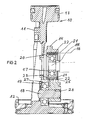
- a piston 10 of a compressor not otherwise shown shown the analog with a high-performance electric motor, not shown EP 12 33 183 A1 can be assembled into a functional unit.
- the Piston 10 is designed as a double piston, which has an elongated piston carrier 11 having at one end a first piston 12 with a large diameter for a first pressure stage and at the opposite end a second piston 13th having a smaller diameter for a second pressure stage. Based on these Design of the piston 10, the compressor not shown in two stages.
- the Piston carrier 11 forms with at least one of the two pistons 12, 13 a one-piece component, the z. B. as a molded part made of plastic or from Die-cast aluminum is formed.
- the piston 10, in particular the piston carrier 11, is connected by means of a connecting rod 14 driven on an eccentric 15 at the end of a shaft 16 by means of a Warehouse 17, z. B. a ball bearing, is rotatably mounted.
- the shaft 16 is part of a Drive device in the form of an electrical not shown High-performance engine.
- the connecting rod 14 extends approximately parallel to the piston carrier 11th and approximately at right angles to the longitudinal center axis of the shaft 16.
- a transverse bolt 18 is fixed to the piston carrier 11 attached, which is thus an integral part of the piston carrier 11 and from this approximately parallel to the longitudinal center axis of the shaft 16 and in the direction of this so far protrudes that the connecting rod 14 by means of a bearing 19, z. B. a ball bearing, so that it is pivotable, in particular rotatable, can be coupled.
- the bearing 19 is seated with its inner ring firmly on the bolt 18, while its outer ring rotatably in the connecting rod 14 is added.
- the other bearing 17, hereinafter referred to as a connecting rod bearing 17, runs in essentially in the same radial plane as the bearing 19, but radially offset to, and sits with its inner ring firmly on the eccentric 15.
- at least one vibration damping device 20 is arranged, which in Area of the coupling site, e.g. the local warehouse 19, and / or - as in Fig. 1 is executed - is provided in the region of the connecting rod bearing 17.
- These Vibration damping device 20 has a vibration damping Bearing receptacle 21, which has a vibration-damping layer 22, which is elastic, in particular made of rubber, synthetic rubber od. Like. Is formed.
- the vibration damping layer 22 has z. B. a hardness of about 80 ° Shore A. on.
- the vibration damping Bearing seat 21 a rubber spring on while at another, not shown embodiment, the bearing seat 21 alone from the vibration damping layer 22 may be formed.
- the bearing seat 21 is Connecting rod bearing 17 with its outer ring directly into the vibration damping Layer 22 embedded, in turn, in a receptacle 23, in particular Bore, is arranged in the connecting rod 14.
- rubber spring has these two concentric rings 24 and 25, in particular of metal, and between the rings 24, 25, the annular extending layer 22, the z. B. formed as vulcanized rubber layer is.
- the vibration-damping bearing seat 21 is the connecting rod bearing 17th embedded in the receptacle 23 of the connecting rod 14.
- the arrangement of the vibration damping device 20 at this point has proved to be particularly beneficial proved.
- the vibration damping layer 22 is designed to be in Circumferential direction has a greater elasticity than in the radial direction, preferably in the radial direction z. B. is relatively rigid.
- the at least one vibration damping device 20 Due to the arrangement of the at least one vibration damping device 20 a very good damping of vibrations is achieved, the arise during the movement process of the piston 10 and over the Connecting rod 14 and the bearings 17 and 19 are transmitted and the other by the drive device not shown further and the eccentric 15 arise. Such vibrations not only burden the bearings but lead to disturbing noises, which are especially unpleasant make noticeable if so trained compressors z. B.in vehicles are installed. Due to the vibration damping device 20 are so Such vibrations in the region of the bearing seat 21 of the layer 22nd Recorded and muted, reducing noise by a Multiple is achieved.
- the second embodiment differs from the first in that in the second embodiment in Fig. 2, the bolt 18 in a bore 26 of the Pleuels 14 is attached, z. B. is pressed, and in the transverse direction in the drawing to the left over the connecting rod 14 and the piston carrier 11 protrudes out, in the Area of the local coupling point the bearing 19 not, as in Fig. 1, in the connecting rod 14th but instead is arranged in a bore 27 of the piston carrier 11, in the bearing 19 is contained with its outer ring, while the bearing inner ring firmly seated on the bolt 18. Also in Fig. 2 is corresponding to the first Embodiment at least one vibration damping device 20 in Provided area of the connecting rod bearing 17, which is designed in the same way as explained above with reference to FIG. 1.
- FIG. 2 may additionally or instead whose bearing 19 of the coupling point by means of a vibration damping Bearing seat 21 in a part of the piston 10, in particular of the piston carrier 11, be embedded.
Landscapes
- Engineering & Computer Science (AREA)
- General Engineering & Computer Science (AREA)
- Mechanical Engineering (AREA)
- Chemical & Material Sciences (AREA)
- Combustion & Propulsion (AREA)
- Compressor (AREA)
- Shafts, Cranks, Connecting Bars, And Related Bearings (AREA)
Abstract
Description
- Fig. 1
- einen schematischen Schnitt eines Kolbens mit daran angreifendem Pleuel eines ansonsten nicht weiter gezeigten Verdichters, gemäß einem ersten Ausführungsbeispiel,
- Fig. 2
- einen schematischen Schnitt eines Kolbens mit daran angreifendem Pleuel ähnlich Fig. 1 gemäß einem zweiten Ausführungsbeispiel.
Claims (13)
- Pleuel für den Kolben eines Verdichters, insbesondere für einen Doppelkolben, das mit einem Abschnitt mittels eines Pleuellagers (17) auf einem Exzenter (15) einer Antriebseinrichtung (16) lagerbar ist und in Abstand davon mit dem Kolben (10) schwenkbeweglich koppelbar ist,
gekennzeichnet durch
zumindest eine Schwingungsdämpfungseinrichtung (20), die im Pleuelverlauf zwischen dem Pleuellager (17) und der Koppelstelle (19) angeordnet ist. - Pleuel nach Anspruch 1,
dadurch gekennzeichnet, dass die Schwingungsdämpfungseinrichtung (20) im Bereich der Koppelstelle, z.B. eines dortigen Lagers (19), vorgesehen ist. - Pleuel nach Anspruch 1,
dadurch gekennzeichnet, dass die Schwingungsdämpfungseinrichtung (20) im Bereich des.Pleuellagers (17) vorgesehen ist. - Pleuel nach einem der Ansprüche 1 bis 3,
dadurch gekennzeichnet, dass die Schwingungsdämpfungseinrichtung (20) eine schwingungsdämpfende Lageraufnahme (21) aufweist. - Pleuel nach Anspruch 4,
dadurch gekennzeichnet, dass die schwingungsdämpfende Lageraufnahme (21)eine schwingungsdämpfende Schicht (22) aufweist. - Pleuel nach Anspruch 5,
dadurch gekennzeichnet, dass die schwingungsdämpfende Schicht (22) der Lageraufnahme (21) elastisch ist, insbesondere aus Gummi, Kunstgummi od. dgl. gebildet ist. - Pleuel nach Anspruch 6 oder 7,
dadurch gekennzeichnet, dass die schwingungsdämpfende Schicht (22) eine Härte von etwa 80° Shore A aufweist. - Pleuel nach einem der Ansprüche 4 bis 7,
dadurch gekennzeichnet, dass die Lageraufnahme allein aus der schwingungsdämpfenden Schicht (22) gebildet ist. - Pleuel nach einem der Ansprüche 4 bis 7,
dadurch gekennzeichnet, dass die schwingungsdämpfende Lageraufnahme (21) eine Gummifeder aufweist. - Pleuel nach Anspruch 9,
dadurch gekennzeichnet, dass die Gummifeder zwei konzentrische Ringe (24, 25), insbesondere aus Metall, und zwischen den Ringen (24, 25) eine ringförmige, z.B. anvulkanisierte, Gummischicht (22) aufweist. - Pleuel nach einem der Ansprüche 5 bis 10,
dadurch gekennzeichnet, dass die schwingungsdämpfende Schicht (22) so ausgelegt ist, dass diese in Umfangsrichtung eine größere Elastizität als in radialer Richtung aufweist, vorzugsweise in radialer Richtung relativ starr ist. - Pleuel nach einem der Ansprüche 1 bis 11,
dadurch gekennzeichnet, dass das Pleuellager (17) mittels der schwingungsdämpfenden Lageraufnahme (21) in das Pleuel (14) eingebettet ist. - Pleuel nach einem der Ansprüche 1 bis 12,
dadurch gekennzeichnet, dass das Lager (19) der Koppelstelle mittels der schwingungsdämpfenden Lageraufnahme (21) in das Pleuel (14) und/oder in einen Teil (11) des Kolbens (10) eingebettet ist.
Priority Applications (1)
| Application Number | Priority Date | Filing Date | Title |
|---|---|---|---|
| PL04008174T PL1479909T3 (pl) | 2003-05-22 | 2004-04-03 | Korbowód tłoka sprężarki |
Applications Claiming Priority (2)
| Application Number | Priority Date | Filing Date | Title |
|---|---|---|---|
| DE10323125 | 2003-05-22 | ||
| DE10323125A DE10323125A1 (de) | 2003-05-22 | 2003-05-22 | Pleuel für den Kolben eines Verdichters |
Publications (2)
| Publication Number | Publication Date |
|---|---|
| EP1479909A1 true EP1479909A1 (de) | 2004-11-24 |
| EP1479909B1 EP1479909B1 (de) | 2006-06-14 |
Family
ID=33039264
Family Applications (1)
| Application Number | Title | Priority Date | Filing Date |
|---|---|---|---|
| EP04008174A Expired - Lifetime EP1479909B1 (de) | 2003-05-22 | 2004-04-03 | Pleuel für den Kolben eines Verdichters |
Country Status (4)
| Country | Link |
|---|---|
| US (1) | US20040231508A1 (de) |
| EP (1) | EP1479909B1 (de) |
| DE (2) | DE10323125A1 (de) |
| PL (1) | PL1479909T3 (de) |
Families Citing this family (6)
| Publication number | Priority date | Publication date | Assignee | Title |
|---|---|---|---|---|
| DE102016001595A1 (de) * | 2016-02-11 | 2017-08-17 | Wabco Gmbh | Hubkolbenmaschine, insbesondere zwei- oder mehrstufiger Kolbenkompressor, Druckluftversorgungsanlage, Druckluftversorgungssystem und Fahrzeug, insbesondere PKW mit einer Druckluftversorgungsanlage |
| DE102018128557A1 (de) | 2018-11-14 | 2020-05-14 | Wabco Gmbh | Hubkolbenmaschine, Druckluftversorgungsanlage, Fahrzeug und Verfahren zur Herstellung einer Hubkolbenmaschine |
| DE102018130887A1 (de) | 2018-12-04 | 2020-06-04 | Amk Holding Gmbh & Co. Kg | Kolbenverdichter |
| DE102020134398A1 (de) | 2020-12-21 | 2022-06-23 | Amk Holding Gmbh & Co. Kg | Kolben und Kolbenverdichter |
| DE102023104247A1 (de) | 2022-02-25 | 2023-08-31 | Amk Holding Gmbh & Co. Kg | Verdichtervorrichtung sowie diesbezügliches Druckluftversorgungssystem, Elektromotor für eine Verdichtervorrichtung und Fahrzeug und Verfahren zum Herstellen einer Verdichtervorrichtung |
| DE102023126663B3 (de) * | 2023-08-10 | 2024-12-24 | Rolls-Royce Solutions GmbH | Kopplungs- und/oder Verbinderstruktur, Verbinderbauteil, Brennkraftmaschine und Verfahren zum Herstellen einer Kopplungs- und/oder Verbinderstruktur |
Citations (4)
| Publication number | Priority date | Publication date | Assignee | Title |
|---|---|---|---|---|
| US2343211A (en) * | 1943-01-26 | 1944-02-29 | Gen Electric | Reciprocating compressor |
| GB2288864A (en) * | 1994-04-23 | 1995-11-01 | Ford Motor Co | Engine with variable compression ratio |
| DE10042214A1 (de) * | 2000-08-28 | 2002-03-14 | Knorr Bremse Systeme | Kolbenkompressor mit einem dynamischen Massenausgleich im Bereich der Kurbeltriebe, insbesondere für Schienenfahrzeuge (Ausgleichspleuel) |
| DE10155776A1 (de) * | 2001-11-14 | 2003-05-22 | Helmut Obieglo | Resonanzförderer |
Family Cites Families (1)
| Publication number | Priority date | Publication date | Assignee | Title |
|---|---|---|---|---|
| US3574293A (en) * | 1968-11-05 | 1971-04-13 | Joseph A Vriend | Antiknock bearing device |
-
2003
- 2003-05-22 DE DE10323125A patent/DE10323125A1/de not_active Withdrawn
-
2004
- 2004-04-03 DE DE502004000745T patent/DE502004000745D1/de not_active Expired - Lifetime
- 2004-04-03 EP EP04008174A patent/EP1479909B1/de not_active Expired - Lifetime
- 2004-04-03 PL PL04008174T patent/PL1479909T3/pl unknown
- 2004-05-17 US US10/847,011 patent/US20040231508A1/en not_active Abandoned
Patent Citations (4)
| Publication number | Priority date | Publication date | Assignee | Title |
|---|---|---|---|---|
| US2343211A (en) * | 1943-01-26 | 1944-02-29 | Gen Electric | Reciprocating compressor |
| GB2288864A (en) * | 1994-04-23 | 1995-11-01 | Ford Motor Co | Engine with variable compression ratio |
| DE10042214A1 (de) * | 2000-08-28 | 2002-03-14 | Knorr Bremse Systeme | Kolbenkompressor mit einem dynamischen Massenausgleich im Bereich der Kurbeltriebe, insbesondere für Schienenfahrzeuge (Ausgleichspleuel) |
| DE10155776A1 (de) * | 2001-11-14 | 2003-05-22 | Helmut Obieglo | Resonanzförderer |
Also Published As
| Publication number | Publication date |
|---|---|
| DE10323125A1 (de) | 2004-12-16 |
| US20040231508A1 (en) | 2004-11-25 |
| PL1479909T3 (pl) | 2006-09-29 |
| DE502004000745D1 (de) | 2006-07-27 |
| EP1479909B1 (de) | 2006-06-14 |
Similar Documents
| Publication | Publication Date | Title |
|---|---|---|
| EP3431815B1 (de) | Riemenspannvorrichtung | |
| DE10063638B4 (de) | Automatische Selbstspannvorrichtung | |
| DE102015222203B4 (de) | Spielfreie Pendellagerung am Entkopplungsspanner | |
| DE19805003B4 (de) | Elektromotor | |
| EP1589224A1 (de) | Doppelkolben für einen Verdichter | |
| DE3590411T (de) | Riemenspannvorrichtung und Herstellungsverfahren | |
| WO2009003829A2 (de) | Dämpfungsvorrichtung eines mechanischen spannsystems für einen zugmitteltrieb | |
| WO2002076797A1 (de) | Scheibenwischvorrichtung, insbesondere für ein kraftfahrzeug sowie verfahren zu deren herstellung | |
| DE102014206716A1 (de) | Riemenspannvorrichtung | |
| EP3960605A1 (de) | Elektrofahrrad-antriebseinheits-befestigungsanordnung | |
| DE102015115750A1 (de) | Riemenspannvorrichtung | |
| DE102010019066A1 (de) | Riemenspanner | |
| EP1479909A1 (de) | Pleuel für den Kolben eines Verdichters | |
| DE102013217257A1 (de) | Hydraulikaggregat einer Fahrzeugbremsanlage mit einem Motorwellenlager | |
| EP0033362A2 (de) | Elastisches Gelenk, Kupplung oder dergleichen | |
| DE102014209780A1 (de) | Exzenterspanner für einen Zugmitteltrieb eines Verbrennungsmotors | |
| EP1736688A2 (de) | Riemenspanner mit aussenliegender Dämpfungshülse | |
| DE102016203074B3 (de) | Getriebemotor | |
| WO2022002575A1 (de) | Elektropneumatisches schlagwerk | |
| DE102004017300A1 (de) | Anordnung zur Dämpfung einer Schwingungsübertragung | |
| EP1736689A2 (de) | Riemenspannvorrichtung zur Befestigung an einem Aggregat | |
| DE19955688A1 (de) | Kolben-Vakuumpumpe | |
| WO2009024418A1 (de) | Riemenspanner | |
| DE3716098A1 (de) | Antriebsvorrichtung fuer pumpen oder dgl. | |
| DE19606002A1 (de) | Spann- oder Gleitschiene für Kettentriebe von Brennkraftmaschinen |
Legal Events
| Date | Code | Title | Description |
|---|---|---|---|
| PUAI | Public reference made under article 153(3) epc to a published international application that has entered the european phase |
Free format text: ORIGINAL CODE: 0009012 |
|
| AK | Designated contracting states |
Kind code of ref document: A1 Designated state(s): AT BE BG CH CY CZ DE DK EE ES FI FR GB GR HU IE IT LI LU MC NL PL PT RO SE SI SK TR |
|
| AX | Request for extension of the european patent |
Extension state: AL HR LT LV MK |
|
| 17P | Request for examination filed |
Effective date: 20050307 |
|
| 17Q | First examination report despatched |
Effective date: 20050429 |
|
| AKX | Designation fees paid |
Designated state(s): CZ DE FR GB IT PL |
|
| RAP1 | Party data changed (applicant data changed or rights of an application transferred) |
Owner name: AMK ARNOLD MUELLER GMBH & CO.KG |
|
| GRAP | Despatch of communication of intention to grant a patent |
Free format text: ORIGINAL CODE: EPIDOSNIGR1 |
|
| GRAS | Grant fee paid |
Free format text: ORIGINAL CODE: EPIDOSNIGR3 |
|
| GRAA | (expected) grant |
Free format text: ORIGINAL CODE: 0009210 |
|
| AK | Designated contracting states |
Kind code of ref document: B1 Designated state(s): CZ DE FR GB IT PL |
|
| PG25 | Lapsed in a contracting state [announced via postgrant information from national office to epo] |
Ref country code: IT Free format text: LAPSE BECAUSE OF FAILURE TO SUBMIT A TRANSLATION OF THE DESCRIPTION OR TO PAY THE FEE WITHIN THE PRESCRIBED TIME-LIMIT;WARNING: LAPSES OF ITALIAN PATENTS WITH EFFECTIVE DATE BEFORE 2007 MAY HAVE OCCURRED AT ANY TIME BEFORE 2007. THE CORRECT EFFECTIVE DATE MAY BE DIFFERENT FROM THE ONE RECORDED. Effective date: 20060614 |
|
| REG | Reference to a national code |
Ref country code: GB Ref legal event code: FG4D Free format text: NOT ENGLISH |
|
| GBT | Gb: translation of ep patent filed (gb section 77(6)(a)/1977) |
Effective date: 20060614 |
|
| REF | Corresponds to: |
Ref document number: 502004000745 Country of ref document: DE Date of ref document: 20060727 Kind code of ref document: P |
|
| ET | Fr: translation filed | ||
| PLBE | No opposition filed within time limit |
Free format text: ORIGINAL CODE: 0009261 |
|
| STAA | Information on the status of an ep patent application or granted ep patent |
Free format text: STATUS: NO OPPOSITION FILED WITHIN TIME LIMIT |
|
| 26N | No opposition filed |
Effective date: 20070315 |
|
| PGRI | Patent reinstated in contracting state [announced from national office to epo] |
Ref country code: IT Effective date: 20080601 |
|
| REG | Reference to a national code |
Ref country code: DE Ref legal event code: R082 Ref document number: 502004000745 Country of ref document: DE Representative=s name: BARTELS & PARTNER PATENTANWAELTE, DE Ref country code: DE Ref legal event code: R082 Ref document number: 502004000745 Country of ref document: DE Representative=s name: BARTELS UND PARTNER PATENTANWAELTE, DE Ref country code: DE Ref legal event code: R082 Ref document number: 502004000745 Country of ref document: DE Representative=s name: STUMPF PATENTANWAELTE PARTGMBB, DE |
|
| REG | Reference to a national code |
Ref country code: FR Ref legal event code: PLFP Year of fee payment: 13 |
|
| REG | Reference to a national code |
Ref country code: DE Ref legal event code: R082 Ref document number: 502004000745 Country of ref document: DE Representative=s name: STUMPF PATENTANWAELTE PARTGMBB, DE |
|
| REG | Reference to a national code |
Ref country code: DE Ref legal event code: R082 Ref document number: 502004000745 Country of ref document: DE Representative=s name: STUMPF PATENTANWAELTE PARTGMBB, DE |
|
| REG | Reference to a national code |
Ref country code: FR Ref legal event code: PLFP Year of fee payment: 14 |
|
| REG | Reference to a national code |
Ref country code: FR Ref legal event code: PLFP Year of fee payment: 15 |
|
| REG | Reference to a national code |
Ref country code: DE Ref legal event code: R082 Ref document number: 502004000745 Country of ref document: DE Representative=s name: STUMPF PATENTANWAELTE PARTGMBB, DE Ref country code: DE Ref legal event code: R081 Ref document number: 502004000745 Country of ref document: DE Owner name: AMK HOLDING GMBH & CO. KG, DE Free format text: FORMER OWNER: AMK ARNOLD MUELLER GMBH & CO. KG, 73230 KIRCHHEIM, DE |
|
| REG | Reference to a national code |
Ref country code: GB Ref legal event code: 732E Free format text: REGISTERED BETWEEN 20191017 AND 20191023 |
|
| PGFP | Annual fee paid to national office [announced via postgrant information from national office to epo] |
Ref country code: CZ Payment date: 20200319 Year of fee payment: 17 |
|
| PGFP | Annual fee paid to national office [announced via postgrant information from national office to epo] |
Ref country code: DE Payment date: 20200401 Year of fee payment: 17 Ref country code: FR Payment date: 20200421 Year of fee payment: 17 |
|
| PGFP | Annual fee paid to national office [announced via postgrant information from national office to epo] |
Ref country code: IT Payment date: 20200423 Year of fee payment: 17 Ref country code: GB Payment date: 20200423 Year of fee payment: 17 |
|
| PG25 | Lapsed in a contracting state [announced via postgrant information from national office to epo] |
Ref country code: CZ Free format text: LAPSE BECAUSE OF NON-PAYMENT OF DUE FEES Effective date: 20210403 |
|
| REG | Reference to a national code |
Ref country code: DE Ref legal event code: R119 Ref document number: 502004000745 Country of ref document: DE |
|
| GBPC | Gb: european patent ceased through non-payment of renewal fee |
Effective date: 20210403 |
|
| PG25 | Lapsed in a contracting state [announced via postgrant information from national office to epo] |
Ref country code: FR Free format text: LAPSE BECAUSE OF NON-PAYMENT OF DUE FEES Effective date: 20210430 Ref country code: GB Free format text: LAPSE BECAUSE OF NON-PAYMENT OF DUE FEES Effective date: 20210403 Ref country code: DE Free format text: LAPSE BECAUSE OF NON-PAYMENT OF DUE FEES Effective date: 20211103 |
|
| PGFP | Annual fee paid to national office [announced via postgrant information from national office to epo] |
Ref country code: PL Payment date: 20200323 Year of fee payment: 17 |
|
| PG25 | Lapsed in a contracting state [announced via postgrant information from national office to epo] |
Ref country code: IT Free format text: LAPSE BECAUSE OF FAILURE TO SUBMIT A TRANSLATION OF THE DESCRIPTION OR TO PAY THE FEE WITHIN THE PRESCRIBED TIME-LIMIT Effective date: 20200403 |
|
| PG25 | Lapsed in a contracting state [announced via postgrant information from national office to epo] |
Ref country code: PL Free format text: LAPSE BECAUSE OF NON-PAYMENT OF DUE FEES Effective date: 20210403 |
|
| PG25 | Lapsed in a contracting state [announced via postgrant information from national office to epo] |
Ref country code: IT Free format text: LAPSE BECAUSE OF NON-PAYMENT OF DUE FEES Effective date: 20210403 |