EP1477451A2 - Uncoiling device for an extension jib of a mobile crane - Google Patents
Uncoiling device for an extension jib of a mobile crane Download PDFInfo
- Publication number
- EP1477451A2 EP1477451A2 EP04006222A EP04006222A EP1477451A2 EP 1477451 A2 EP1477451 A2 EP 1477451A2 EP 04006222 A EP04006222 A EP 04006222A EP 04006222 A EP04006222 A EP 04006222A EP 1477451 A2 EP1477451 A2 EP 1477451A2
- Authority
- EP
- European Patent Office
- Prior art keywords
- folding
- folding tip
- bending device
- telescopic
- tip bending
- Prior art date
- Legal status (The legal status is an assumption and is not a legal conclusion. Google has not performed a legal analysis and makes no representation as to the accuracy of the status listed.)
- Granted
Links
- 238000005452 bending Methods 0.000 claims abstract description 25
- 125000006850 spacer group Chemical group 0.000 claims description 4
- 238000010276 construction Methods 0.000 description 4
- 238000003466 welding Methods 0.000 description 3
- 238000004519 manufacturing process Methods 0.000 description 2
- 230000002787 reinforcement Effects 0.000 description 2
- 229910000831 Steel Inorganic materials 0.000 description 1
- 238000001514 detection method Methods 0.000 description 1
- 239000012530 fluid Substances 0.000 description 1
- 238000003780 insertion Methods 0.000 description 1
- 230000037431 insertion Effects 0.000 description 1
- 238000012986 modification Methods 0.000 description 1
- 230000004048 modification Effects 0.000 description 1
- 238000012544 monitoring process Methods 0.000 description 1
- 230000008092 positive effect Effects 0.000 description 1
- 239000010959 steel Substances 0.000 description 1
Images


Classifications
-
- B—PERFORMING OPERATIONS; TRANSPORTING
- B66—HOISTING; LIFTING; HAULING
- B66C—CRANES; LOAD-ENGAGING ELEMENTS OR DEVICES FOR CRANES, CAPSTANS, WINCHES, OR TACKLES
- B66C23/00—Cranes comprising essentially a beam, boom, or triangular structure acting as a cantilever and mounted for translatory of swinging movements in vertical or horizontal planes or a combination of such movements, e.g. jib-cranes, derricks, tower cranes
- B66C23/62—Constructional features or details
- B66C23/64—Jibs
- B66C23/70—Jibs constructed of sections adapted to be assembled to form jibs or various lengths
- B66C23/701—Jibs constructed of sections adapted to be assembled to form jibs or various lengths telescopic
- B66C23/702—Jibs constructed of sections adapted to be assembled to form jibs or various lengths telescopic with a jib extension boom
Definitions
- the present invention relates to a folding tip bending device for a mobile crane.
- folding tips serve as extension arms Mobile cranes.
- the mobile crane 20 carries one on his outermost shot attached folding tip 10, which by means of a Bending device 9 can be angled so that a projection over the edge of the building is made possible.
- folding tip bending devices There are two different types of folding tip bending devices in the prior art known. On the one hand, it is mechanical adjustable rods in the upper or tensile load area of the joint area and on the other hand, hydraulic cylinder bending devices in the lower or Pressure area of the joint area.
- FIG. 2 shows a bending device according to the prior art a hydraulic cylinder 17 in the lower pressure load area of the joint area 9 ' shown.
- the hydraulic cylinder 17 is a via the inflow and outflow Hydraulic fluids controlled and thus changed in length. This has the advantage that the angle adjustment from the crane cab in all main boom positions can be operated. Unfortunately, high production costs arise, that are not always accepted.
- Figure 3 shows the "mechanical solution” according to the prior art, in which mechanically adjustable rods 16 are present in the joint area 9 ′′ in the upper tensile load range.
- the disadvantage of such a construction is that they do not replace the hydraulic cylinder version ( Figure 2) without major modifications can.
- the Basic construction of hydraulically angled tips can be used to to provide an inexpensive mechanically adjustable tip in a short time.
- adjustment measures for the folding tip angle should be easy and can be carried out safely.
- this object is achieved by a folding-tip bending device solved according to claim 1.
- the sub-claims defined advantageous embodiments of the invention.
- a folding jib bending device for a mobile crane with a Joint area, by the angle of which the angle of the folding tip is adjusted and which has a joint in the upper or in the tensile load range, are based Advantages of the invention that the joint area in the lower or Compressed load area has a mechanically lockable telescopic device.
- this is a hydraulic-free one Telescoping device is provided, which only includes funds to their mechanical adjustment and locking in desired lengths are.
- such a solution offers a relatively inexpensive alternative because the costs for expensive hydraulic cylinders, for the hydraulic supply and the Control and monitoring can be saved.
- the Telescopic device on a telescopic tube In a preferred embodiment of the invention, the Telescopic device on a telescopic tube.
- the telescopic device or that Telescopic tube can advantageously have support elements by means of it can be determined mechanically in different lengths.
- the telescopic device or the Telescopic tube on a support element and an extendable element.
- the Bracket element is articulated on the side towards the base of the folding tip attached to the joint area, and the extendable element is articulated to the The tip of the folding tip is attached to the side of the joint area. It So the same fastenings in the lower or pressure load range used as with hydraulic cylinders, which is the replacement of the Hydraulic cylinder makes it possible in a simple manner.
- the support elements for the extendable element can be arranged on the mounting element.
- the telescopic device In the lower or pressure load range, the telescopic device only has to do so be designed so that they angled the upper part of the folding tip against the Base of the folding tip supports.
- the support is sufficient, it does not necessarily have to be one bi-directional detection is provided, i.e. the upper part the folding tip is sufficiently determined if a in the telescopic device one-sided support against a further reduction of the folding tip angle for Available.
- the attachment of the bracket to the base of the folding tip located side of the joint area forms according to a preferred Embodiment of the invention one of the support devices.
- This component leaves use themselves in two ways and on the one hand ensures that Joint attachment and on the other hand for the counter support of the largest pre-adjustable tip angle.
- the telescopic device advantageously has a round or angular one Base tube (as a support element) and an extendable piston (as an extendable Element) on, with the base tube cross holes for receiving support bolts has, which support the piston at its lower end.
- the telescopic device has a fuse that prevents its Parts of the telescope come apart.
- this backup be a spacer sleeve between the lower, supporting end of the extendable element and the upper end of the mounting element is and can serve as a fall protection for the folding seats.
- This backup or Spacer preferably limits the maximum length of the telescopic device.
- FIGS. 4 and 5 show the expensive embodiment of a bending device with a hydraulic cylinder according to the prior art ( Figure 4) one Execution according to the invention compared.
- Figure 4 shows the Articulated area 9 'of the folding tip, with a pressure load on the lower side is present, a hydraulic cylinder 17 is arranged between two joints.
- Figure 5 instead of the hydraulic cylinder, a telescopic tube 7 is used.
- a telescopic tube 7 is used instead of the hydraulic cylinder.
- the Telescopic tube 7 has the base tube 7a and the extendable piston 7b the positions designated 1 and 1 'as shown in Figure 5 on the folding tip be articulated.
- the base tube 7a and the extendable piston 7b, the here is also designed as a tube, can be completely prefabricated and then simply pushed into each other. By inserting or The length of the bolt can be omitted, which will be discussed in more detail later Overall arrangement, that is, the total length of the telescopic tube 7 can be changed.
- the base tube 7a has a cross section the point with the bolt 2 in Figure 6 shows cross holes, one of which with the reference numeral 6 is indicated.
- Support bolts 2 are used, one of which is shown in Figure 6.
- This Support bolts support the lower part of the piston 7b (on different Set) in certain lengths for the entire telescopic tube 7.
- the base tube 7a does not have to be processed on the inside.
- the centering is over the Bolt 2 and the fillet or groove in the piston crown 3 in one axis and in the other axis by the piston 7b and those provided with the reference numeral 4 Welding hubs realized so that the guide is independent of the Manufacturing tolerances of the pipe is.
- the welding hubs 4 form how 7, reinforcements on the edges of the Through holes 6, the surface pressure due to larger sheet thicknesses can be reduced between bolt 2 and pipe wall.
- the welding hubs 4 thus have two functions, namely the centering of the piston 7b in the one hand Base tube 7a and on the other hand the reinforcement as support elements in the area of Through holes.
- the bolt in the bearing 1 ( Figures 5 and 6) in addition to its function as a hinge pin as a counter bearing (support) for the piston 7b can be used in the inserted state. This will make the dead length reduced and the overlap when extended extended. The bigger one Overlap has a positive effect on buckling safety.
- the spacer sleeve 5 is shown, which the Pulling apart of the telescopic tube prevented, so that the folding tip in can not "tip over" when it is not angled. Since the lower opening on the base tube 7a a simple pushing the parts 7a and 7b enables the piston crown 3 to be firmly connected to the piston tube. A simple assembly of the telescopic tube 7 is thus possible.
- the piston crown 3 can also be designed to be removable.
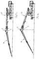
- FIGS. 9 and 10 show the erection of the jib of a mobile crane 20 the folding tip 10. Since the piston 7b, as shown in Figures 5 to 8, only on one side on one of the selected or inserted bolts (2 or 1) supports, the setting of the bolts can easily be done in a state at which the crane tip has no or only a very small angle, as in Figure 9 is shown. In the state shown in FIG. 9, the End angle position by inserting the bolt into the base tube 7a Telescopic tube 7 can be set at the desired location. If so, as in 10, the boom is raised, the telescopic tube 7 is shortened until the piston 7b hits the pin (2 or 1) and is supported on it. In FIG.
- the special construction according to the present invention makes it possible to the desired angle of the folding tip (length of the telescopic tube) with small Select the main boom angle. The tip then angles when lifting the Main boom until the telescopic tube has reached the preselected length. It is no further securing of the tip required, making all setup work in Near the ground are possible. So it becomes an inexpensive alternative to expensive ones Hydraulic cylinder devices provided by the invention that are convenient Set up on the ground without risk of accident.
Landscapes
- Engineering & Computer Science (AREA)
- Mechanical Engineering (AREA)
- Jib Cranes (AREA)
- Mutual Connection Of Rods And Tubes (AREA)
Abstract
Description
Die vorliegende Erfindung betrifft eine Klappspitzen-Abwinklungsvorrichtung für
einen Mobilkran. Solche Klappspitzen dienen als Auslegerverlängerung an
Mobilkranen. Um beispielsweise über Gebäudekanten eine größere Ausladung bei
gleicher Krangröße zu erreichen, ist es erforderlich, die Klappspitze abzuwinkeln. Ein
solcher Einsatz ist in der beiliegenden Figur 1 gezeigt. Um über der Oberkante des
Hochhauses 30 arbeiten zu können, trägt der Mobilkran 20 eine an seinem
äußersten Schuss befestigte Klappspitze 10, die mittels einer
Abwinklungsvorrichtung 9 so abgewinkelt werden kann, dass eine Ausladung über
der Gebäudekante ermöglicht wird.The present invention relates to a folding tip bending device for
a mobile crane. Such folding tips serve as extension arms
Mobile cranes. In order, for example, to have a larger projection over the edges of the building
To achieve the same crane size, it is necessary to bend the folding tip. On
such use is shown in the accompanying Figure 1. To over the top of the
To be able to work high-
Es sind im Stand der Technik zwei unterschiedliche Arten von Klappspitzen-Abwinklungsvorrichtungen bekannt. Dabei handelt es sich einerseits um mechanisch einstellbare Stangen im oberen bzw. Zuglast-Bereich des Gelenkbereiches und andererseits um Hydraulikzylinder-Abwinklungsvorrichtungen im unteren bzw. Druckbereich des Gelenkbereiches.There are two different types of folding tip bending devices in the prior art known. On the one hand, it is mechanical adjustable rods in the upper or tensile load area of the joint area and on the other hand, hydraulic cylinder bending devices in the lower or Pressure area of the joint area.
In der Figur 2 ist eine Abwinklungsvorrichtung gemäß dem Stand der Technik mit
einem Hydraulikzylinder 17 im unteren Drucklast-Bereich des Gelenkbereiches 9'
gezeigt. Der Hydraulikzylinder 17 wird über die Zu- und Abströmung eines
Hydraulikfluides angesteuert und damit in der Länge verändert. Dies hat den Vorteil,
dass die Winkelverstellung aus der Krankabine in allen Hauptauslegerstellungen
bedient werden kann. Nachteiligerweise entstehen aber hohe Herstellungskosten,
die nicht immer akzeptiert werden.FIG. 2 shows a bending device according to the prior art
a
Die Figur 3 zeigt die "mechanische Lösung" gemäß dem Stand der Technik, bei der
mechanisch einstellbare Stangen 16 im Gelenkbereich 9" vorhanden sind, und zwar
im oberen Zuglast-Bereich. Der Nachteil einer solchen Konstruktion liegt darin, dass
sie nicht ohne größere Umbauten die Hydraulikzylinder-Version (Figur 2) ersetzen
kann.Figure 3 shows the "mechanical solution" according to the prior art, in which
mechanically
Es ist die Aufgabe der vorliegenden Erfindung, eine Klappspitzen-Abwinklungseinrichtung bereitzustellen, welche die oben aufgezeigten Nachteile des Standes der Technik vermeidet. Insbesondere soll dafür gesorgt werden, dass die Grundkonstruktion hydraulisch abwinkelbarer Spitzen verwendet werden kann, um eine kostengünstige mechanisch zu verstellende Spitze in kurzer Zeit bereitzustellen. Ferner sollen auch Einstellmaßnahmen für den Klappspitzenwinkel leicht und ungefährlich durchgeführt werden können.It is the object of the present invention to provide a folding tip bending device To provide, which have the disadvantages of Avoid prior art. In particular, it should be ensured that the Basic construction of hydraulically angled tips can be used to to provide an inexpensive mechanically adjustable tip in a short time. Furthermore, adjustment measures for the folding tip angle should be easy and can be carried out safely.
Diese Aufgabe wird erfindungsgemäß durch eine Klappspitzen-Abwinklungsvorrichtung gemäß Anspruch 1 gelöst. Die Unteransprüche definierten vorteilhafte Ausführungsformen der Erfindung.According to the invention, this object is achieved by a folding-tip bending device solved according to claim 1. The sub-claims defined advantageous embodiments of the invention.
Bei einer Klappspitzen-Abwinklungsvorrichtung für einen Mobilkran, mit einem Gelenkbereich, durch dessen Abwinklung der Winkel der Klappspitze eingestellt wird und der ein Gelenk im oberen bzw. im Zuglast-Bereich aufweist, beruhen die erfindungsgemäßen Vorteile darauf, dass der Gelenkbereich im unteren bzw. im Drucklast-Bereich eine mechanisch feststellbare Teleskopiereinrichtung aufweist. Mit anderen Worten wird hier im Gegensatz zu dem Hydraulikzylinder eine hydraulikfreie Teleskopiereinrichtung zur Verfügung gestellt, die lediglich Mittel umfasst, die zu ihrer mechanischen Verstellung und Feststellung in gewünschten Längen geeignet sind. Einerseits bietet eine solche Lösung eine relativ kostengünstige Alternative, da die Kosten für teure Hydraulikzylinder, für die Hydraulikversorgung und die Steuerung und Überwachung eingespart werden können. Andererseits kann ein solcher teurer Hydraulikzylinder ohne weiteres durch eine mechanisch feststellbare Teleskopiereinrichtung ersetzt werden, die im unteren bzw. im Drucklast-Bereich des Gelenkbereiches eingebaut ist, so dass alle Stahlbauteile der hydraulisch abwinkelbaren Spitze verwendet werden können und ohne zu großen Aufwand bei Verwendung vieler Gleichteile ein kostengünstige, rein mechanisch verstellbare Klappspitze angeboten werden kann. In a folding jib bending device for a mobile crane, with a Joint area, by the angle of which the angle of the folding tip is adjusted and which has a joint in the upper or in the tensile load range, are based Advantages of the invention that the joint area in the lower or Compressed load area has a mechanically lockable telescopic device. With in other words, in contrast to the hydraulic cylinder, this is a hydraulic-free one Telescoping device is provided, which only includes funds to their mechanical adjustment and locking in desired lengths are. On the one hand, such a solution offers a relatively inexpensive alternative because the costs for expensive hydraulic cylinders, for the hydraulic supply and the Control and monitoring can be saved. On the other hand, a such expensive hydraulic cylinder easily by a mechanically lockable Telescopic device to be replaced in the lower or in the pressure load range of the Joint area is installed, so that all steel components of the hydraulic bendable tip can be used and without too much effort Use of many identical parts an inexpensive, purely mechanically adjustable Folding tip can be offered.
Bei einer bevorzugten Ausführungsform der Erfindung weist die Teleskopiereinrichtung ein Teleskoprohr auf. Die Teleskopiereinrichtung bzw. das Teleskoprohr können vorteilhafterweise Abstützelemente aufweisen, mittels der sie/es in unterschiedlichen Längen mechanisch feststellbar ist.In a preferred embodiment of the invention, the Telescopic device on a telescopic tube. The telescopic device or that Telescopic tube can advantageously have support elements by means of it can be determined mechanically in different lengths.
Bei einer Ausführungsvariante weist die Teleskopiereinrichtung bzw. das Teleskoprohr ein Halterungselement und ein ausfahrbares Element auf. Das Halterungselement ist gelenkig an der zur Basis der Klappspitze hin gelegenen Seite des Gelenkbereiches befestigt, und das ausfahrbare Element ist gelenkig an der zur Spitze der Klappspitze hin gelegenen Seite des Gelenkbereiches befestigt. Es werden also die gleichen Befestigungen im unteren bzw. Drucklast-Bereich verwendet wie bei Hydraulikzylindern, was die oben schon erwähnte Ersetzung des Hydraulikzylinders in einfacher Weise möglich macht. Die Abstützelemente für das ausfahrbare Element können am Halterungselement angeordnet sein.In one embodiment variant, the telescopic device or the Telescopic tube on a support element and an extendable element. The Bracket element is articulated on the side towards the base of the folding tip attached to the joint area, and the extendable element is articulated to the The tip of the folding tip is attached to the side of the joint area. It So the same fastenings in the lower or pressure load range used as with hydraulic cylinders, which is the replacement of the Hydraulic cylinder makes it possible in a simple manner. The support elements for the extendable element can be arranged on the mounting element.
Im unteren bzw. Drucklast-Bereich muss die Teleskopiereinrichtung lediglich so ausgelegt sein, dass sie den oberen Teil der Klappspitze abgewinkelt gegen die Basis der Klappspitze abstützt. Die Abstützung genügt, es muss nicht unbedingt eine in beiden Richtungen wirkende Feststellung bereitgestellt werden, d.h. der obere Teil der Klappspitze ist ausreichend festgestellt, wenn in der Teleskopiereinrichtung eine einseitige Abstützung gegen eine weitere Verkleinerung des Klappspitzenwinkels zur Verfügung steht. Hieraus resultiert nun der Vorteil, dass die Einstellung des letztendlichen Klappspitzenwinkels schon am Boden geschehen kann, und zwar dann, wenn der gesamte Ausleger mit Klappspitze sehr nahe über dem Boden abgelegt wird. In diesem Zustand wird das ausgewählte Abstützelement installiert, wobei der Gelenkbereich in geringer Höhe über dem Boden liegt und Unfallgefahr vermieden wird. Erst bei Anheben des Auslegers verschiebt sich die Teleskopiereinrichtung dann solange, bis das Abstützelement sperrt und einen bestimmten Winkel einstellt. Es kann also eine unkomplizierte und ungefährliche Vorabeinstellung des Klappspitzenwinkels am Boden erfolgen.In the lower or pressure load range, the telescopic device only has to do so be designed so that they angled the upper part of the folding tip against the Base of the folding tip supports. The support is sufficient, it does not necessarily have to be one bi-directional detection is provided, i.e. the upper part the folding tip is sufficiently determined if a in the telescopic device one-sided support against a further reduction of the folding tip angle for Available. This now has the advantage that the setting of the ultimate folding tip angle can already happen on the ground, namely then when the entire jib with jib is very close to the ground is filed. In this state, the selected support element is installed, the joint area is at a low height above the ground and risk of accident is avoided. It only moves when the boom is lifted Telescope then until the support element locks and one sets a certain angle. So it can be a straightforward and safe The tip of the folding tip is pre-set on the floor.
Die Befestigung des Halterungselements an der zur Basis der Klappspitze hin gelegenen Seite des Gelenkbereiches bildet gemäß einer bevorzugten Ausführungsform der Erfindung eine der Abstützvorrichtungen. Dieses Bauteil lässt sich also in zweifacher Weise verwenden und sorgt einerseits für die Gelenkbefestigung und andererseits für den Gegenhalt bei dem größten voreinstellbaren Klappspitzenwinkel.The attachment of the bracket to the base of the folding tip located side of the joint area forms according to a preferred Embodiment of the invention one of the support devices. This component leaves use themselves in two ways and on the one hand ensures that Joint attachment and on the other hand for the counter support of the largest pre-adjustable tip angle.
Vorteilhafterweise weist die Teleskopiereinrichtung ein rundes oder eckiges Basisrohr (als Halterungselement) und einen ausfahrbaren Kolben (als ausfahrbares Element) auf, wobei das Basisrohr Querbohrungen zur Aufnahme von Abstützbolzen aufweist, die den Kolben an seinem unteren Ende abstützen.The telescopic device advantageously has a round or angular one Base tube (as a support element) and an extendable piston (as an extendable Element) on, with the base tube cross holes for receiving support bolts has, which support the piston at its lower end.
Es ist ferner möglich, bei einer Konstruktion mit Basisrohr und ausfahrbarem Kolben am Basisrohr seitliche Einsätze vorzusehen, welche zur Führung des Kolbens dienen, und außerdem können diese seitlichen Einsätze Naben für die Querbohrungen bilden und so wiederum zwei Funktionen erfüllen. Vorteilhafterweise weist die Teleskopiereinrichtung eine Sicherung auf, die verhindert, dass ihre Teleskopbestandteile sich voneinander lösen. Insbesondere kann diese Sicherung eine Distanzhülse sein, die zwischen dem unteren, abstützenden Ende des ausfahrbaren Elements und dem oberen Ende des Halterungselementes angeordnet ist und als Rückfallsicherung für die Klappsitze dienen kann. Diese Sicherung oder Distanzhülse begrenzt bevorzugt die Maximallänge der Teleskopiereinrichtung.It is also possible for a construction with a base tube and an extendable piston Provide lateral inserts on the base tube, which are used to guide the piston serve, and also these side inserts hubs for the Form cross holes and thus in turn fulfill two functions. advantageously, the telescopic device has a fuse that prevents its Parts of the telescope come apart. In particular, this backup be a spacer sleeve between the lower, supporting end of the extendable element and the upper end of the mounting element is and can serve as a fall protection for the folding seats. This backup or Spacer preferably limits the maximum length of the telescopic device.
Die hierin beschriebenen Merkmale der vorliegenden Erfindung können einzeln und in jedweder Kombination in verschiedenen Ausführungsformen umgesetzt werden. Eine bevorzugte Ausführungsform wird im Weiteren anhand der beiliegenden Zeichnungen näher erläutert. Es zeigen:
- Figur 1
- einen Mobilkran mit einer Klappspitze über einem Hochhaus;
Figur 2- einen Gelenkbereich für eine Klappspitze nach dem Stand der Technik mit einem Hydraulikzylinder;
Figur 3- einen Gelenkbereich für eine Klappspitze nach dem Stand der Technik mit Stangenverstellung;
- Figuren 4 und 5
- eine Gegenüberstellung eines Gelenkbereiches mit Hydraulikzylinder gemäß dem Stand der Technik und eines Gelenkbereiches mit einem Teleskoprohr gemäß der vorliegenden Erfindung;
Figuren 6 bis 8- Einzelheiten des Teleskoprohres der Klappspitzen-Abwinklungsvorrichtung gemäß der vorliegenden Erfindung; und
Figuren 9 und 10- die Abwinklung der Klappspitze beim Anheben eines Auslegers, mit einer Abwinklungsvorrichtung gemäß der vorliegenden Erfindung.
- Figure 1
- a mobile crane with a folding jib above a skyscraper;
- Figure 2
- a hinge area for a folding tip according to the prior art with a hydraulic cylinder;
- Figure 3
- a joint area for a folding tip according to the prior art with rod adjustment;
- Figures 4 and 5
- a comparison of a joint area with hydraulic cylinder according to the prior art and a joint area with a telescopic tube according to the present invention;
- Figures 6 to 8
- Details of the telescopic tube of the folding tip bending device according to the present invention; and
- Figures 9 and 10
- the bending of the folding tip when lifting a boom, with a bending device according to the present invention.
In den Figuren 4 und 5 ist die teure Ausführungsform einer Abwinklungsvorrichtung
mit einem Hydraulikzylinder gemäß dem Stand der Technik (Figur 4) einer
erfindungsgemäßen Ausführung gegenüber gestellt. Die Figur 4 zeigt den
Gelenkbereich 9' der Klappspitze, wobei an der unteren Seite, an der eine Drucklast
vorliegt, ein Hydraulikzylinder 17 zwischen zwei Gelenken angeordnet ist. Um diese
- wie oben erläutert - teure und aufwendige Ausführung zu vereinfachen und eine
kostengünstige Alternative bereitzustellen, wird nun gemäß der Erfindung (Figur 5)
anstelle des Hydraulikzylinders ein Teleskoprohr 7 eingesetzt. Dabei können alle
restlichen Bauteile der Klappspitze bzw. des Gelenkbereichs 9 weiterverwendet
werden. Das zur rechten Seite in Figur 5 hin verlaufende Oberteil der Klappspitze
schwenkt um das Gelenk 8, wobei ein Winkel eingestellt wird, der durch die Länge
des Teleskoprohrs 7 vorgegeben wird, dessen Basisrohr 7a und Kolbenrohr 7b sich
je nach Einbringung der Abstützelemente (diese werden später erläutert) in einer
bestimmten Stellung aneinander abstützen und somit eine gewisse Länge und
Winkelstellung vorgeben. In Figur 5 ist ferner noch zu sehen, dass die
Gelenkverbindungen 1 und 1' für das Teleskoprohr an exakt denselben Stellen
angreifen wie diejenigen des in Figur 4 gezeigten Hydraulikzylinders 17.FIGS. 4 and 5 show the expensive embodiment of a bending device
with a hydraulic cylinder according to the prior art (Figure 4) one
Execution according to the invention compared. Figure 4 shows the
Articulated area 9 'of the folding tip, with a pressure load on the lower side
is present, a
Einzelheiten des Teleskoprohrs 7 sind in den Figuren 6 bis 8 dargestellt. Das
Teleskoprohr weist das Basisrohr 7a und den ausfahrbaren Kolben 7b auf, die an
dem mit 1 und 1' bezeichneten Stellen wie in Figur 5 dargestellt an der Klappspitze
gelenkig angebracht werden. Das Basisrohr 7a und der ausfahrbare Kolben 7b, der
hier ebenfalls als Rohr ausgebildet ist, können komplett vorgefertigt und
anschließend einfach ineinandergeschoben werden. Durch ein Einstecken bzw.
Weglassen von Bolzen, die später detaillierter erörtert werden, kann die Länge der
Gesamtanordnung, also die Gesamtlänge des Teleskoprohres 7 verändert werden. Details of the
Das Basisrohr 7a weist, wie auch aus Figur 7 hervorgeht, die einen Querschnitt an
der Stelle mit dem Bolzen 2 in Figur 6 zeigt, Querbohrungen auf, von denen eine mit
dem Bezugszeichen 6 angedeutet ist. In diese Querbohrungen können
Abstützbolzen 2 eingesetzt werden, von denen einer in Figur 6 gezeigt ist. Diese
Abstützbolzen stützen den unteren Teil des Kolbens 7b (an unterschiedlichen
Stellen) in bestimmten Längen für das Gesamt-Teleskoprohr 7 ab. Das Basisrohr 7a
muss nicht an der Innenseite bearbeitet werden. Die Zentrierung wird über den
Bolzen 2 und die Ausrundung oder Nut im Kolbenboden 3 in einer Achse und in der
anderen Achse durch den Kolben 7b und die mit dem Bezugszeichen 4 versehenen
Einschweißnaben realisiert, so dass die Führung unabhängig von den
Herstellungstoleranzen des Rohres ist. Die Einschweißnaben 4 bilden, wie
insbesondere aus Figur 7 hervorgeht, Verstärkungen an den Rändern der
Durchgangsbohrungen 6, wobei durch größere Blechstärken die Flächenpressung
zwischen Bolzen 2 und Rohrwand verringert werden kann. Die Einschweißnaben 4
haben also zwei Funktionen, nämlich einerseits die Zentrierung des Kolbens 7b im
Basisrohr 7a und andererseits die Verstärkung als Stützelemente im Bereich der
Durchgangsbohrungen.As can also be seen from FIG. 7, the
Besonders vorteilhaft ist, dass der Bolzen im Lager 1 (Figur 5 und 6) zusätzlich zu seiner Funktion als Gelenkbolzen noch als Gegenlager (Abstützung) für den Kolben 7b im eingeschobenen Zustand genutzt werden kann. Hierdurch wird die Totlänge reduziert und die Überlappung im ausgeschobenen Zustand vergrößert. Die größere Überlappung wirkt sich positiv auf die Knicksicherheit aus.It is particularly advantageous that the bolt in the bearing 1 (Figures 5 and 6) in addition to its function as a hinge pin as a counter bearing (support) for the piston 7b can be used in the inserted state. This will make the dead length reduced and the overlap when extended extended. The bigger one Overlap has a positive effect on buckling safety.
In den Figuren 6 und 8 ist noch die Distanzhülse 5 aufgezeigt, welche das
Auseinanderziehen des Teleskoprohres verhindert, so dass die Klappspitze auch im
nicht abgewinkelten Zustand keineswegs nach hinten "umkippen" kann. Da die
untere Öffnung am Basisrohr 7a ein einfaches Ineinanderschieben der Teile 7a und
7b ermöglicht, kann der Kolbenboden 3 fest mit dem Kolbenrohr verbunden sein.
Damit ist eine einfache Montage des Teleskoprohres 7 möglich. Der Kolbenboden 3
kann auch abnehmbar ausgestaltet sein.In Figures 6 and 8, the
Die Figuren 9 und 10 zeigen das Aufstellen des Auslegers eines Mobilkrans 20 mit
der Klappspitze 10. Da der Kolben 7b, wie in den Figuren 5 bis 8 dargestellt, sich
lediglich einseitig auf einem der ausgewählten bzw. eingesteckten Bolzen (2 oder 1)
abstützt, kann das Setzen der Bolzen ohne weiteres in einem Zustand erfolgen, bei
dem die Kranspitze keine oder eine nur sehr kleine Abwinklung aufweist, wie in Figur
9 gezeigt ist. In dem in Figur 9 gezeigten Zustand kann in relativ geringer Höhe die
Endwinkelstellung durch das Setzen des Bolzens in das Basisrohr 7a des
Teleskoprohrs 7 an der gewünschten Stelle eingestellt werden. Wenn dann, wie in
Figur 10 gezeigt, der Ausleger angehoben wird, verkürzt sich das Teleskoprohr 7
solange, bis der Kolben 7b auf den Bolzen (2 bzw. 1) trifft und sich daran abstützt. In
Figur 10 ist ein Zustand gezeigt, bei dem die kürzeste Länge des Teleskoprohrs als
Endstellung gewählt wird, hierbei wird sich der Kolben auf den Gelenkbolzen 1
abstützen (siehe Figur 6). Danach kann der Ausleger mit der abwinkelbaren
Klappspitze oder Wippspitze 10 völlig angehoben und sicher betrieben werden.FIGS. 9 and 10 show the erection of the jib of a
Durch die besondere Konstruktion gemäß der vorliegenden Erfindung ist es möglich, den gewünschten Winkel der Klappspitze (Länge des Teleskoprohres) bei kleinem Hauptauslegerwinkel vorzuwählen. Die Spitze winkelt dann beim Anheben des Hauptauslegers ab, bis das Teleskoprohr die vorgewählte Länge erreicht hat. Es ist kein weiteres Sichern der Spitze erforderlich, wodurch alle Rüstarbeiten in Bodennähe möglich sind. Es wird also eine kostengünstige Alternative zu teuren Hydraulikzylinder-Vorrichtungen durch die Erfindung bereitgestellt, die ein bequemes Rüsten am Boden ohne Unfallgefahr ermöglicht.The special construction according to the present invention makes it possible to the desired angle of the folding tip (length of the telescopic tube) with small Select the main boom angle. The tip then angles when lifting the Main boom until the telescopic tube has reached the preselected length. It is no further securing of the tip required, making all setup work in Near the ground are possible. So it becomes an inexpensive alternative to expensive ones Hydraulic cylinder devices provided by the invention that are convenient Set up on the ground without risk of accident.
Claims (12)
Applications Claiming Priority (2)
| Application Number | Priority Date | Filing Date | Title |
|---|---|---|---|
| DE10321493 | 2003-05-13 | ||
| DE10321493A DE10321493B4 (en) | 2003-05-13 | 2003-05-13 | Folding pinnacle bending |
Publications (3)
| Publication Number | Publication Date |
|---|---|
| EP1477451A2 true EP1477451A2 (en) | 2004-11-17 |
| EP1477451A3 EP1477451A3 (en) | 2005-11-16 |
| EP1477451B1 EP1477451B1 (en) | 2007-02-28 |
Family
ID=33016375
Family Applications (1)
| Application Number | Title | Priority Date | Filing Date |
|---|---|---|---|
| EP04006222A Expired - Lifetime EP1477451B1 (en) | 2003-05-13 | 2004-03-16 | Uncoiling device for an extension jib of a mobile crane |
Country Status (7)
| Country | Link |
|---|---|
| US (1) | US7131548B2 (en) |
| EP (1) | EP1477451B1 (en) |
| JP (1) | JP4727946B2 (en) |
| CN (1) | CN100354195C (en) |
| CA (1) | CA2465464C (en) |
| DE (2) | DE10321493B4 (en) |
| ES (1) | ES2279244T3 (en) |
Cited By (4)
| Publication number | Priority date | Publication date | Assignee | Title |
|---|---|---|---|---|
| WO2009026870A1 (en) * | 2007-08-29 | 2009-03-05 | Terex-Demag Gmbh | Element for connecting a lattice system |
| DE202008015659U1 (en) | 2008-11-26 | 2009-03-19 | Palfinger Ag | Crane tip for a loading crane |
| WO2009033198A1 (en) * | 2007-09-11 | 2009-03-19 | Franz Ehrenleitner | Folding boom |
| EP2253576A1 (en) | 2009-05-22 | 2010-11-24 | Terex Demag GmbH | Angle adjustment of a jib system |
Families Citing this family (21)
| Publication number | Priority date | Publication date | Assignee | Title |
|---|---|---|---|---|
| DE102005049606B4 (en) * | 2005-10-17 | 2016-03-31 | Liebherr-Werk Ehingen Gmbh | Mobile crane with additional boom and procedure for disassembling the jib |
| US7878346B1 (en) | 2008-08-25 | 2011-02-01 | Link-Belt Construction Equipment Co., L.P., Lllp | Adaptable boom extension for a mobile crane having a telescoping boom |
| DE102009010452A1 (en) * | 2009-02-26 | 2010-09-02 | Terex-Demag Gmbh | Method and device for mounting and dismounting an attachment on the main boom of a mobile crane |
| US8739988B2 (en) * | 2010-09-20 | 2014-06-03 | Manitowoc Crane Companies, Llc | Pinned connection system for crane column segments |
| DE202010014104U1 (en) * | 2010-10-08 | 2012-01-10 | Liebherr-Werk Ehingen Gmbh | Boom element, outrigger and construction vehicle |
| JP5609686B2 (en) * | 2011-02-04 | 2014-10-22 | コベルコクレーン株式会社 | Mobile crane |
| CN102718156B (en) * | 2012-06-29 | 2014-05-21 | 三一重工股份有限公司 | Crane arm support system and crane |
| CN102756978A (en) * | 2012-07-20 | 2012-10-31 | 辽宁抚挖重工机械股份有限公司 | Foldable arm of crawler crane |
| DE102013006259A1 (en) * | 2013-04-11 | 2014-10-16 | Liebherr-Werk Ehingen Gmbh | Telescopic boom and crane |
| CN103449319B (en) * | 2013-09-06 | 2015-12-02 | 中联重科股份有限公司 | Crane arm and hoisting crane |
| CN103601084B (en) * | 2013-11-29 | 2015-08-12 | 三一汽车起重机械有限公司 | Arm point pulley mechanism, arm point pulley mechanism from assembly and disassembly methods and hoisting crane |
| CN104071710B (en) * | 2014-07-01 | 2017-08-25 | 徐工集团工程机械股份有限公司 | A kind of crane and its stepless variable-amplitude auxiliary arm device |
| DE102015002626A1 (en) * | 2015-03-03 | 2016-09-08 | Liebherr-Werk Ehingen Gmbh | Telescopic boom of a crane and method for its bracing, as well as for erecting telescopic extensions |
| CN105060140B (en) * | 2015-08-19 | 2018-03-16 | 徐州重型机械有限公司 | Auxiliary, crane arm and the crane of crane |
| DE102015119379B3 (en) | 2015-11-10 | 2017-03-30 | Terex Global Gmbh | Mobile crane and method for bending a main boom extension relative to a main boom of a mobile crane |
| DE102015119381B3 (en) * | 2015-11-10 | 2017-04-27 | Terex Global Gmbh | Mobile crane and method for bending a main boom extension relative to a main boom of a mobile crane |
| DE102015120350B3 (en) | 2015-11-24 | 2017-05-24 | Terex Global Gmbh | Mobile crane for bending a main boom extension relative to a main boom of a mobile crane |
| CN106241628A (en) * | 2016-08-25 | 2016-12-21 | 徐州重型机械有限公司 | Truss arm structure and crane |
| DE102018115519B3 (en) * | 2018-06-27 | 2019-09-12 | Terex Global Gmbh | Mobile crane with a movable adapter between main boom and main boom extension |
| CN110193869A (en) * | 2019-07-09 | 2019-09-03 | 邢珊珊 | A kind of wood processing machine of the pressing mechanism containing folding |
| CN111943063B (en) * | 2020-08-19 | 2022-08-12 | 东台市杰顺机械制造有限公司 | Flexible fastening lifting device for flywheel housing processing production |
Citations (3)
| Publication number | Priority date | Publication date | Assignee | Title |
|---|---|---|---|---|
| US3944082A (en) * | 1974-12-20 | 1976-03-16 | Harnischfeger Corporation | Locking means for relatively movable boom sections of boom of mobile crane |
| DE9318480U1 (en) * | 1993-12-02 | 1994-03-10 | Buck Erwin | Pallet truck for lifting, lowering and transporting loads |
| FR2719574A1 (en) * | 1994-05-06 | 1995-11-10 | Ppm | Extension assembly for telescopic crane jib |
Family Cites Families (31)
| Publication number | Priority date | Publication date | Assignee | Title |
|---|---|---|---|---|
| DE291531C (en) | ||||
| US2147313A (en) * | 1936-06-23 | 1939-02-14 | Payson Rudolph | Telescopic hoisting apparatus |
| US2198793A (en) * | 1937-09-02 | 1940-04-30 | Yale & Towne Mfg Co | Tilting boom |
| US2512150A (en) * | 1947-01-08 | 1950-06-20 | Airquipment Company | Hydraulic ram mechanism having shielding and stop means |
| US3092261A (en) * | 1960-03-23 | 1963-06-04 | Patent Resources Inc | Crane boom safety apparatus |
| US3085695A (en) * | 1961-03-23 | 1963-04-16 | Carl A Miller | Hinge for crane boom |
| US3638804A (en) * | 1969-09-17 | 1972-02-01 | Pacific Gas Equipment Co | Hoisting apparatus |
| US3754666A (en) * | 1970-03-09 | 1973-08-28 | Hopper Inc | Folding crane |
| US3899089A (en) * | 1974-02-05 | 1975-08-12 | N J Wardlaw | Removable mounted hoist for pick-up truck |
| SU619588A1 (en) * | 1976-10-20 | 1978-08-15 | Строительно-Монтажное Управление N1 Треста "Востокпроводмеханизация" | Hydraulic excavator working equipment |
| FR2444639A1 (en) * | 1978-12-20 | 1980-07-18 | Potain Sa | HANDLING EQUIPMENT, PARTICULARLY FOR A SELF-PROPELLED MACHINE |
| DD139830B1 (en) * | 1978-12-21 | 1982-10-27 | Horst Bendix | SUPPLEMENTARY TO RAIL SPECIAL CRANES OR THE LIKE |
| US4484686A (en) * | 1982-04-23 | 1984-11-27 | Kidde, Inc. | Multiple offset boom extension |
| JPS59173689A (en) * | 1983-03-23 | 1984-10-01 | Hitachi Ltd | Heat transmission device |
| JPS6043690A (en) * | 1983-08-19 | 1985-03-08 | 三洋電機株式会社 | Crt terminal |
| GB2160170A (en) * | 1984-06-15 | 1985-12-18 | Didsbury Eng | Davit (especially for vehicles) |
| US4621742A (en) * | 1985-01-25 | 1986-11-11 | Harnischfeger Corporation | Boom extension storage means and mechanisms |
| JPH07115831B2 (en) * | 1988-05-06 | 1995-12-13 | 株式会社神戸製鋼所 | Jib overhang and storage device for crane |
| US4953724A (en) * | 1989-06-29 | 1990-09-04 | Kabushiki Kaisha Kobe Seiko Sho | Jib stretching and folding device |
| CA2015519C (en) * | 1989-08-10 | 1994-09-27 | Yukio Koizumi | Jib stretching and folding device for crane |
| DD291531A5 (en) * | 1990-01-08 | 1991-07-04 | Maschinenbau "Karl Marx",De | BOOMS WITH ONE DEVICE FOR ONE OR MULTIPLE TIPPABLE BOOM EXTENSIONS FOR CRANES, ESPECIALLY MOBILE CRANES |
| JP2781637B2 (en) * | 1990-03-16 | 1998-07-30 | 株式会社神戸製鋼所 | Jib support rod mounting device for crane |
| CA2036895A1 (en) * | 1991-02-22 | 1992-08-23 | James Vandervalk | Mobile crane |
| US5725112A (en) * | 1991-12-17 | 1998-03-10 | Thorby; Donald Frederick | Crane |
| US5758785A (en) * | 1995-06-22 | 1998-06-02 | Spinosa; Dominic | Lifting system |
| US5704498A (en) * | 1996-09-25 | 1998-01-06 | Kidde Industries, Inc. | Transportable crane |
| DE19731587A1 (en) * | 1997-07-17 | 1999-01-28 | Mannesmann Ag | Telescopic crane with luffing jib |
| CN1242337A (en) * | 1998-07-01 | 2000-01-26 | 美国格若沃责任有限公司 | Transportable crane |
| DE19932009A1 (en) * | 1998-07-07 | 2000-01-27 | Mannesmann Ag | Mobile crane with sectional telescopic jib-arm |
| FR2794734B1 (en) * | 1999-06-10 | 2001-07-13 | Potain Sa | SELF-PROPELLED TROLLEY WITH TELESCOPIC ARM AND BOOSTER |
| ITMI20010116A1 (en) * | 2001-01-23 | 2002-07-23 | San Marco Internat S R L | TOWER CRANE WITH SELF-ASSEMBLING STRUCTURE WITH FOLDABLE AND REMOVABLE TOWER AND ARM WITH MULTIPLE PORTIONS |
-
2003
- 2003-05-13 DE DE10321493A patent/DE10321493B4/en not_active Expired - Fee Related
-
2004
- 2004-03-16 DE DE502004003002T patent/DE502004003002D1/en not_active Expired - Lifetime
- 2004-03-16 ES ES04006222T patent/ES2279244T3/en not_active Expired - Lifetime
- 2004-03-16 EP EP04006222A patent/EP1477451B1/en not_active Expired - Lifetime
- 2004-04-20 US US10/827,242 patent/US7131548B2/en active Active
- 2004-04-27 CA CA002465464A patent/CA2465464C/en not_active Expired - Fee Related
- 2004-05-11 JP JP2004141181A patent/JP4727946B2/en active Active
- 2004-05-13 CN CNB200410043130XA patent/CN100354195C/en not_active Expired - Fee Related
Patent Citations (3)
| Publication number | Priority date | Publication date | Assignee | Title |
|---|---|---|---|---|
| US3944082A (en) * | 1974-12-20 | 1976-03-16 | Harnischfeger Corporation | Locking means for relatively movable boom sections of boom of mobile crane |
| DE9318480U1 (en) * | 1993-12-02 | 1994-03-10 | Buck Erwin | Pallet truck for lifting, lowering and transporting loads |
| FR2719574A1 (en) * | 1994-05-06 | 1995-11-10 | Ppm | Extension assembly for telescopic crane jib |
Cited By (6)
| Publication number | Priority date | Publication date | Assignee | Title |
|---|---|---|---|---|
| WO2009026870A1 (en) * | 2007-08-29 | 2009-03-05 | Terex-Demag Gmbh | Element for connecting a lattice system |
| US8414214B2 (en) | 2007-08-29 | 2013-04-09 | Terex Cranes Germany Gmbh | Element for connecting a lattice system |
| WO2009033198A1 (en) * | 2007-09-11 | 2009-03-19 | Franz Ehrenleitner | Folding boom |
| DE202008015659U1 (en) | 2008-11-26 | 2009-03-19 | Palfinger Ag | Crane tip for a loading crane |
| EP2253576A1 (en) | 2009-05-22 | 2010-11-24 | Terex Demag GmbH | Angle adjustment of a jib system |
| DE102009022262A1 (en) | 2009-05-22 | 2010-11-25 | Terex Demag Gmbh | Angular adjustment of a boom system |
Also Published As
| Publication number | Publication date |
|---|---|
| DE10321493A1 (en) | 2004-12-23 |
| CN1621334A (en) | 2005-06-01 |
| US20050011850A1 (en) | 2005-01-20 |
| DE502004003002D1 (en) | 2007-04-12 |
| EP1477451A3 (en) | 2005-11-16 |
| US7131548B2 (en) | 2006-11-07 |
| DE10321493B4 (en) | 2006-07-20 |
| CA2465464A1 (en) | 2004-11-13 |
| JP2004338953A (en) | 2004-12-02 |
| JP4727946B2 (en) | 2011-07-20 |
| CA2465464C (en) | 2010-01-19 |
| CN100354195C (en) | 2007-12-12 |
| ES2279244T3 (en) | 2007-08-16 |
| EP1477451B1 (en) | 2007-02-28 |
Similar Documents
| Publication | Publication Date | Title |
|---|---|---|
| EP1477451B1 (en) | Uncoiling device for an extension jib of a mobile crane | |
| EP3337752B1 (en) | Mobile crane and method for angling a main boom extension in relation to a main boom of a mobile crane | |
| WO2002064911A2 (en) | Distribution device for thick matter, especially for concrete | |
| DE102015119379B3 (en) | Mobile crane and method for bending a main boom extension relative to a main boom of a mobile crane | |
| DE102011115355B4 (en) | Boom element, telescopic boom and construction vehicle | |
| EP2465809A1 (en) | Telescopic system for crane boom and jib | |
| EP2067737B1 (en) | Side bracing for a grid extension of a crane | |
| EP3564182B1 (en) | Automatic concrete pump | |
| EP2288770A2 (en) | Device for demolishing constructions | |
| DE102013011173B4 (en) | Method for assembling a crane as well as articulation, telescopic boom and crane | |
| EP3556718B1 (en) | Concrete pump vehicle | |
| DE102011115357B4 (en) | Boom element, telescopic boom, bolt system and construction vehicle | |
| EP3477018B1 (en) | Hollow two point lever | |
| DE202016005419U1 (en) | Crane and counterweight for a crane | |
| DE102019104142B4 (en) | Foldable suspended ballast guide for a crane | |
| EP0893392A2 (en) | Telescopic crane with luffable jib extension | |
| EP3558858A1 (en) | Crane having a collapsible jib | |
| EP1373120B1 (en) | Telescopic boom for a vehicle crane | |
| DE202016100483U1 (en) | Vehicle light crane with telescopic folding tip | |
| EP3543197B1 (en) | Device for applying a ladder section of a crane operator lift to a crane mast | |
| DE102011010042A1 (en) | Three boom for e.g. displacing tombs, has leg divided into two leg sections, which are guided into each other and provided with adjusting device that mechanically continuously telescopes total leg length under load | |
| EP1936108B1 (en) | Stabilising strut for a ladder or scaffolding | |
| EP0685422B1 (en) | Device for erecting and aligning of a self-erecting crane | |
| WO2021032529A1 (en) | Telescopic jib with swing-out mast | |
| DE202009013085U1 (en) | mobile crane |
Legal Events
| Date | Code | Title | Description |
|---|---|---|---|
| PUAI | Public reference made under article 153(3) epc to a published international application that has entered the european phase |
Free format text: ORIGINAL CODE: 0009012 |
|
| AK | Designated contracting states |
Kind code of ref document: A2 Designated state(s): AT BE BG CH CY CZ DE DK EE ES FI FR GB GR HU IE IT LI LU MC NL PL PT RO SE SI SK TR |
|
| AX | Request for extension of the european patent |
Extension state: AL LT LV MK |
|
| PUAL | Search report despatched |
Free format text: ORIGINAL CODE: 0009013 |
|
| AK | Designated contracting states |
Kind code of ref document: A3 Designated state(s): AT BE BG CH CY CZ DE DK EE ES FI FR GB GR HU IE IT LI LU MC NL PL PT RO SE SI SK TR |
|
| AX | Request for extension of the european patent |
Extension state: AL LT LV MK |
|
| 17P | Request for examination filed |
Effective date: 20060118 |
|
| AKX | Designation fees paid |
Designated state(s): DE ES FR GB IT |
|
| GRAP | Despatch of communication of intention to grant a patent |
Free format text: ORIGINAL CODE: EPIDOSNIGR1 |
|
| GRAS | Grant fee paid |
Free format text: ORIGINAL CODE: EPIDOSNIGR3 |
|
| GRAA | (expected) grant |
Free format text: ORIGINAL CODE: 0009210 |
|
| AK | Designated contracting states |
Kind code of ref document: B1 Designated state(s): DE ES FR GB IT |
|
| REG | Reference to a national code |
Ref country code: GB Ref legal event code: FG4D Free format text: NOT ENGLISH |
|
| GBT | Gb: translation of ep patent filed (gb section 77(6)(a)/1977) |
Effective date: 20070228 |
|
| REF | Corresponds to: |
Ref document number: 502004003002 Country of ref document: DE Date of ref document: 20070412 Kind code of ref document: P |
|
| REG | Reference to a national code |
Ref country code: ES Ref legal event code: FG2A Ref document number: 2279244 Country of ref document: ES Kind code of ref document: T3 |
|
| ET | Fr: translation filed | ||
| PLBE | No opposition filed within time limit |
Free format text: ORIGINAL CODE: 0009261 |
|
| STAA | Information on the status of an ep patent application or granted ep patent |
Free format text: STATUS: NO OPPOSITION FILED WITHIN TIME LIMIT |
|
| 26N | No opposition filed |
Effective date: 20071129 |
|
| REG | Reference to a national code |
Ref country code: GB Ref legal event code: 732E Free format text: REGISTERED BETWEEN 20110915 AND 20110921 |
|
| REG | Reference to a national code |
Ref country code: FR Ref legal event code: TP Owner name: MANITOWOC CRANE GROUP FRANCE, FR Effective date: 20110920 |
|
| REG | Reference to a national code |
Ref country code: ES Ref legal event code: PC2A Owner name: MANITOWOC CRANE GROUP FRANCE SAS Effective date: 20111027 |
|
| REG | Reference to a national code |
Ref country code: DE Ref legal event code: R082 Ref document number: 502004003002 Country of ref document: DE Representative=s name: SCHWABE SANDMAIR MARX, DE |
|
| REG | Reference to a national code |
Ref country code: DE Ref legal event code: R081 Ref document number: 502004003002 Country of ref document: DE Owner name: MANITOWOC CRANE GROUP FRANCE SAS, FR Free format text: FORMER OWNER: GROVE U.S. LLC, SHADY GROVE, PA., US Effective date: 20120330 Ref country code: DE Ref legal event code: R082 Ref document number: 502004003002 Country of ref document: DE Representative=s name: SCHWABE SANDMAIR MARX, DE Effective date: 20120330 Ref country code: DE Ref legal event code: R081 Ref document number: 502004003002 Country of ref document: DE Owner name: MANITOWOC CRANE GROUP FRANCE SAS, FR Free format text: FORMER OWNER: GROVE U.S. LLC, SHADY GROVE, US Effective date: 20120330 Ref country code: DE Ref legal event code: R082 Ref document number: 502004003002 Country of ref document: DE Representative=s name: SCHWABE SANDMAIR MARX PATENTANWAELTE RECHTSANW, DE Effective date: 20120330 |
|
| PGFP | Annual fee paid to national office [announced via postgrant information from national office to epo] |
Ref country code: GB Payment date: 20130321 Year of fee payment: 10 |
|
| GBPC | Gb: european patent ceased through non-payment of renewal fee |
Effective date: 20140316 |
|
| PG25 | Lapsed in a contracting state [announced via postgrant information from national office to epo] |
Ref country code: GB Free format text: LAPSE BECAUSE OF NON-PAYMENT OF DUE FEES Effective date: 20140316 |
|
| REG | Reference to a national code |
Ref country code: DE Ref legal event code: R082 Ref document number: 502004003002 Country of ref document: DE Representative=s name: SCHWABE SANDMAIR MARX, DE |
|
| REG | Reference to a national code |
Ref country code: DE Ref legal event code: R081 Ref document number: 502004003002 Country of ref document: DE Owner name: MANITOWOC CRANE GROUP FRANCE SAS, FR Free format text: FORMER OWNER: MANITOWOC CRANE GROUP FRANCE SAS, ECULLY, FR Effective date: 20150317 Ref country code: DE Ref legal event code: R082 Ref document number: 502004003002 Country of ref document: DE Representative=s name: SCHWABE SANDMAIR MARX, DE Effective date: 20150317 Ref country code: DE Ref legal event code: R082 Ref document number: 502004003002 Country of ref document: DE Representative=s name: SCHWABE SANDMAIR MARX PATENTANWAELTE RECHTSANW, DE Effective date: 20150317 |
|
| REG | Reference to a national code |
Ref country code: FR Ref legal event code: PLFP Year of fee payment: 13 |
|
| REG | Reference to a national code |
Ref country code: FR Ref legal event code: PLFP Year of fee payment: 14 |
|
| REG | Reference to a national code |
Ref country code: FR Ref legal event code: PLFP Year of fee payment: 15 |
|
| PGFP | Annual fee paid to national office [announced via postgrant information from national office to epo] |
Ref country code: ES Payment date: 20200522 Year of fee payment: 17 |
|
| REG | Reference to a national code |
Ref country code: ES Ref legal event code: FD2A Effective date: 20220523 |
|
| PG25 | Lapsed in a contracting state [announced via postgrant information from national office to epo] |
Ref country code: ES Free format text: LAPSE BECAUSE OF NON-PAYMENT OF DUE FEES Effective date: 20210317 |
|
| PGFP | Annual fee paid to national office [announced via postgrant information from national office to epo] |
Ref country code: FR Payment date: 20230321 Year of fee payment: 20 |
|
| PGFP | Annual fee paid to national office [announced via postgrant information from national office to epo] |
Ref country code: DE Payment date: 20230321 Year of fee payment: 20 |
|
| P01 | Opt-out of the competence of the unified patent court (upc) registered |
Effective date: 20230515 |
|
| PGFP | Annual fee paid to national office [announced via postgrant information from national office to epo] |
Ref country code: IT Payment date: 20230328 Year of fee payment: 20 |
|
| REG | Reference to a national code |
Ref country code: DE Ref legal event code: R071 Ref document number: 502004003002 Country of ref document: DE |