EP1476938B1 - Vorrichtung zum erzeugen von schwingungen im hochfrequenz-bereich - Google Patents
Vorrichtung zum erzeugen von schwingungen im hochfrequenz-bereich Download PDFInfo
- Publication number
- EP1476938B1 EP1476938B1 EP02798263A EP02798263A EP1476938B1 EP 1476938 B1 EP1476938 B1 EP 1476938B1 EP 02798263 A EP02798263 A EP 02798263A EP 02798263 A EP02798263 A EP 02798263A EP 1476938 B1 EP1476938 B1 EP 1476938B1
- Authority
- EP
- European Patent Office
- Prior art keywords
- base body
- gunn
- circuit arrangement
- connection
- bias choke
- Prior art date
- Legal status (The legal status is an assumption and is not a legal conclusion. Google has not performed a legal analysis and makes no representation as to the accuracy of the status listed.)
- Expired - Lifetime
Links
- 230000010355 oscillation Effects 0.000 title claims abstract description 6
- 238000005476 soldering Methods 0.000 claims description 5
- 239000000853 adhesive Substances 0.000 claims description 3
- 230000001070 adhesive effect Effects 0.000 claims description 3
- 229910052751 metal Inorganic materials 0.000 claims description 3
- 239000002184 metal Substances 0.000 claims description 3
- 239000004020 conductor Substances 0.000 claims 4
- 238000004026 adhesive bonding Methods 0.000 claims 1
- 239000003795 chemical substances by application Substances 0.000 claims 1
- 239000011810 insulating material Substances 0.000 claims 1
- 230000001629 suppression Effects 0.000 description 4
- 239000003990 capacitor Substances 0.000 description 3
- 238000011161 development Methods 0.000 description 2
- 230000018109 developmental process Effects 0.000 description 2
- 230000001105 regulatory effect Effects 0.000 description 2
- 230000007704 transition Effects 0.000 description 2
- 229910000952 Be alloy Inorganic materials 0.000 description 1
- 238000001514 detection method Methods 0.000 description 1
- 230000014509 gene expression Effects 0.000 description 1
- 238000009434 installation Methods 0.000 description 1
- 230000033001 locomotion Effects 0.000 description 1
- 238000004519 manufacturing process Methods 0.000 description 1
- 239000000463 material Substances 0.000 description 1
- 238000000034 method Methods 0.000 description 1
- 229910000679 solder Inorganic materials 0.000 description 1
- 229910000859 α-Fe Inorganic materials 0.000 description 1
Images
Classifications
-
- H—ELECTRICITY
- H03—ELECTRONIC CIRCUITRY
- H03B—GENERATION OF OSCILLATIONS, DIRECTLY OR BY FREQUENCY-CHANGING, BY CIRCUITS EMPLOYING ACTIVE ELEMENTS WHICH OPERATE IN A NON-SWITCHING MANNER; GENERATION OF NOISE BY SUCH CIRCUITS
- H03B9/00—Generation of oscillations using transit-time effects
- H03B9/12—Generation of oscillations using transit-time effects using solid state devices, e.g. Gunn-effect devices
- H03B9/14—Generation of oscillations using transit-time effects using solid state devices, e.g. Gunn-effect devices and elements comprising distributed inductance and capacitance
- H03B9/145—Generation of oscillations using transit-time effects using solid state devices, e.g. Gunn-effect devices and elements comprising distributed inductance and capacitance the frequency being determined by a cavity resonator, e.g. a hollow waveguide cavity or a coaxial cavity
- H03B9/146—Generation of oscillations using transit-time effects using solid state devices, e.g. Gunn-effect devices and elements comprising distributed inductance and capacitance the frequency being determined by a cavity resonator, e.g. a hollow waveguide cavity or a coaxial cavity formed by a disc, e.g. a waveguide cap resonator
Definitions
- the present invention relates to a device according to the preamble of claim 1 (see WO 99/03002 A1 from the prior art; see. furthermore also the publication en US Pat. No. 6,218,916 B1 . WO9903002 . US5126696 as well as the publication of GL LAN et al., "A W-band channeled monolithic receiver", IEEE MICROWAVE AND MILLIMETER-WAVE MONOLITHIC CIRCUITS SYMPOSIUM, 1989, June 12, 1989, pp. 95-99 ).
- Gunn elements are used to generate the electromagnetic oscillations.
- Such Gunn elements can each be arranged in a housing (cf., for example, the publication DE 199 06 205 A1 ).
- H (och) F (requency) sources here Gunn oscillators, for example, 77 gigahertz used. These Gunn oscillators are connected in known embodiments via a screwable waveguide connection with suitable transitions (so-called “step-transformers”), which feed the high-frequency energy into planar distribution networks. The supply of the DC supply voltage is carried out via a hand soldered cable connection in the rule.
- the present invention has the object, a device of the type mentioned in such a way that it can be mounted in a simple, inexpensive and fast way.
- At least one planar mountable or S (face) M (ounted) D (evice) mountable Gunn oscillator according to claim 1 provided (S (urface) M (ounted) D (evice) device surface mounted device), which is formed on at least one circuit board-like , in substantially planar extending electrical or electronic circuitry, in particular electrical or electronic H (och) F (requency) circuitry, can be mounted.
- a particularly durable, efficient and reliable connection to the H (och) F (requency) circuit can take place here via adhesive technology or via soldering technology or via a combination of these two techniques.
- the voltage is not supplied by means of separate soldering (as is the case in the prior art), but by at least one integrated spring member. Furthermore, it is also essential to the invention that the suppression capacitors do not require an additional printed circuit board.
- the present invention relates to at least one device designed in particular as a vehicle radar device for detecting and / or adaptively regulating the distance of a means of locomotion with respect to at least one object, comprising at least one device of the type set forth above.
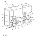
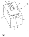
- FIGS. 1 and 2 illustrated embodiment explained in more detail.
- FIGS. 1 and 2 From the perspective representations of FIGS. 1 and 2 is a so-called Gunn oscillator, that is, a device 100 for generating electromagnetic oscillations in H (och) F (requency) range, namely in the gigahertz range (GHz range), out.
- This device 100 is part of a device designed as a vehicle radar device for detecting and adaptively regulating the distance of a motor vehicle.
- FIG. 1 shows a device 100 which, like an electronic S (face) M (ounted) D (evice) device, is directly mounted on a H-plate F (requency) planar circuit can.
- This gun oscillator 100 has a metallic main body 20 in the form of an oscillator block with a rectangular or round waveguide 22 introduced.
- this rectangular or round waveguide 22 projects the actual Gunn diode 10, which is pressed with its integrated heatsink 12 in a first bore 26 of the body 20 and is additionally secured there with a caulking 14 against expressions.
- bias choke 16 is mounted in a further bore 28 of the main body 20.
- This bias choke 16 includes (as in known per se also) a resonator disk and H (och) F (requency) filter structures.
- an insulating plastic body 30 is attached by means of a clip connection 40.
- a metallic conductive (connecting) element 50 is introduced, which is preferably injected directly during manufacture of the plastic part 30 with.
- the conductive element 50 has at its one end 52 an integrally formed spring structure 60, which exerts a force on the bias choke 16 and thus provides for the connection of the bias choke 16 with the Gunn diode 10.
- the spring member 60 is a copper-beryllium alloy, which has both good spring properties and good conductivity.
- a separate spring element can alternatively also be mounted.
- the design of the resilient region is in this context such that between the spring and the bias choke 16, an annular ferrite 62nd can be introduced, which is required for the suppression of unwanted current oscillations of the supply.
- the plastic element 30 also has a particular conical bore 32 in which the end of the bias choke 16 is guided to catch any, during assembly or caused by vibration in the vehicle use transverse forces.
- the other end 54 of the injected metal part 50 is formed like a terminal leg of an electronic component and dimensioned such that the pad 70 of the leg forms a plane with the exit surface 24 of the waveguide 22 from the oscillator block 20.
- the exit surface 24 on the oscillator block 20 further has a recess 80, which allows the passage of the H (och) F (requency) line on the planar circuit. Furthermore, grooves 90 are provided for capturing excess amounts of conductive adhesive or solder.
- FIGS. 1 and 2 note:
- the Gunn oscillator 100 shown here can be equipped like an electronic component on the H (och) F (requenz) circuit, wherein the voltage supply to the legs 54 of the injected metal part 50 is contacted, while the ground connection on the end face of the oscillator block 20 takes place.
- both contacts are made in a fully automated operation.
- the basis of the embodiment according to the FIGS. 1 and 2 set-up of the Gunn oscillator 100 also has the advantage that possibly additionally required suppression capacitors can be accommodated very close to the DC voltage pin 54 on the H (och) F (requency) circuit with.
- the additional printed circuit board used in known oscillator designs can be dispensed with close to the bias choke 16.
Landscapes
- Radar Systems Or Details Thereof (AREA)
- Shielding Devices Or Components To Electric Or Magnetic Fields (AREA)
Abstract
Description
- Die vorliegende Erfindung betrifft eine Vorrichtung gemäß dem Oberbegriff des Anspruchs 1 (vgl. Druckschrift
WO 99/03002 A1 US 6 218 916 B1 ,WO9903002 US5126696 sowie die Veröffentlichung von G. L. LAN et al., "A W-band channelized monolithic receiver", IEEE MICROWAVE AND MILLIMETER-WAVE MONOLITHIC CIRCUITS SYMPOSIUM, 1989, 12. Juni 1989, Seiten 95 bis 99). - Bei H(och)F(requenz)- und Höchstfrequenz-Schaltungen (Frequenz f größer als fünfzig Gigahertz) werden zum Erzeugen der elektromagnetischen Schwingungen Gunn-Elemente eingesetzt. Derartige Gunn-Elemente können jeweils in einem Gehäuse angeordnet sein (vgl. etwa die Druckschrift
DE 199 06 205 A1 ). - Für Anwendungen in Fahrzeug-Radargeräten zur Abstandserkennung und -regelung kommen als H(och)F(requenz)-Quellen hierbei Gunn-Oszillatoren bei beispielsweise 77 Gigahertz zum Einsatz. Diese Gunn-Oszillatoren sind in bekannten Ausgestaltungsformen über eine schraubbare Hohlleiter-Verbindung mit geeigneten Übergängen (sogenannte "Step-Transformer") verbunden, die die hochfrequente Energie in planare Verteilnetzwerke einspeisen. Die Zuführung der Versorgungsgleichspannung erfolgt hierbei über eine im Regelfall handgelötete Kabelverbindung.
- Allerdings ist bei dieser Art des Übergangs mindestens eine Flanschverbindung mit Verschraubung und mit Passtiften vorgesehen, wodurch die Vorrichtung aufwendig wird sowie umständlich zu montieren ist; des weiteren muß gemäß dem Stand der Technik die Spannungszuführung separat gelötet werden; schließlich benötigen angeordnete Entstörkondensatoren konventionellerweise eine zusätzliche Leiterplatte.
- Ausgehend von den vorstehend dargelegten Nachteilen und Unzulänglichkeiten sowie unter Würdigung des umrissenen Standes der Technik liegt der vorliegenden Erfindung die Aufgabe zugrunde, eine Vorrichtung der eingangs genannten Art so auszubilden, daß diese auf einfache, kostengünstige und schnelle Art montiert werden kann.
- Diese Aufgabe wird durch eine Vorrichtung mit den im Anspruch 1 angegebenen Merkmalen gelöst. Vorteilhafte Ausgestaltungen und zweckmäßige Weiterbildungen der vorliegenden Erfindung sind in den Unteransprüchen gekennzeichnet.
- Gemäß der Lehre der vorliegenden Erfindung ist mithin mindestens ein planar bestückbarer oder S(urface)M(ounted)D(evice)-bestückbarer Gunn-Oszillator gemäβ Anspruch 1 vorgesehen (S(urface)M(ounted)D(evice)-Bauelement = oberflächenmontiertes Bauelement), der auf mindestens einer leiterplattenartig ausgebildeten, sich im wesentlichen planar erstreckenden elektrischen oder elektronischen Schaltungsanordnung, insbesondere elektrischen oder elektronischen H(och)F(requenz)-Schaltungsanordnung, montierbar ist.
- Es ist besonders vorteilhaft, daß durch eine einfache Montage des Gunn-Oszillators, insbesondere mittels Clip- oder Steckverbindung, die konventionellerweise anzuordnenden Flanschverbindungen einschließlich der Verschraubung und der Passtifte entfallen können. Eine besonders dauerhafte, effiziente und zuverlässige Verbindung zur H(och)F(requenz)-Schaltung kann hierbei über Klebetechnik oder über Löttechnik oder über eine Kombination dieser beiden Techniken erfolgen.
- Gemäß einer besonders erfinderischen Weiterbildung der vorliegenden Vorrichtung erfolgt die Spannungszuführung nicht mittels separater Lötung (so wie dies im Stand der Technik der Fall ist), sondern durch mindestens ein integriertes Federteil. Des weiteren ist auch von erfindungswesentlichem Vorteil, daß die Entstörkondensatoren keine Zusatz-Leiterplatte benötigen.
- Die vorliegende Erfindung betrifft , schließlich mindestens eine insbesondere als Fahrzeug-Radargerät ausgebildete Einrichtung zum Erkennen und/oder zum adaptiven Regeln des Abstands eines Fortbewegungsmittels in bezug auf mindestens ein Objekt, aufweisend mindestens einer Vorrichtung der vorstehend dargelegten Art.
- Weitere Ausgestaltungen, Merkmale und Vorteile der vorliegenden Erfindung werden nachstehend anhand des durch die
Figuren 1 und2 veranschaulichten Ausführungsbeispiels näher erläutert. - Es zeigt:
- Fig. 1
- eine perspektivische Seitenansicht eines Ausführungsbeispiels einer Vorrichtung gemäß der vorliegenden Erfindung; und
- Fig. 2
- eine perspektivische Unteransicht der Vorrichtung aus
Fig. 1 . - Gleiche oder ähnliche Ausgestaltungen, Elemente oder Merkmale sind in den
Figuren 1 und2 mit identischen Bezugszeichen versehen. - Aus den perspektivischen Darstellungen der
Figuren 1 und2 geht ein sogenannter Gunn-Oszillator, das heißt eine Vorrichtung 100 zum Erzeugen elektromagnetischer Schwingungen im H(och)F(requenz)-Bereich, nämlich im Gigahertzbereich (GHz-Bereich), hervor. Diese Vorrichtung 100 ist Teil einer als Fahrzeug-Radargerät ausgebildeten Einrichtung zum Erkennen und zum adaptiven Regeln des Abstands eines Kraftfahrzeugs. - Im Gegensatz zu den Ausführungsformen gemäß dem Stand der Technik ist in den
Figuren 1 und2 eine Vorrichtung 100 gezeigt, die ähnlich wie ein elektronisches S(urface)M(ounted)D(evice)-Bauelement direkt auf eine leiterplattenartige planare H(och)F(requenz)-Schaltung bestückt werden kann. - Dieser Gun-Oszillator 100 weist einen metallischen Grundkörper 20 in Form eines Oszillatorblocks mit eingebrachtem Rechteck- oder Rund-Hohlleiter 22 auf. In diesen Rechteck- oder Rund-Hohlleiter 22 ragt die eigentliche Gunn-Diode 10, die mit ihrer integrierten Heatsink 12 in eine erste Bohrung 26 des Grundkörpers 20 eingepreßt ist und dort zusätzlich mit einer Verstemmung 14 gegen Ausdrücken gesichert wird.
- Gegenüberliegend ist der spannungszuführende sogenannte Bias-Choke 16 in einer weiteren Bohrung 28 des Grundkörpers 20 montiert. Dieser Bias-Choke 16 beinhaltet (wie in an sich bekannten Ausführungsformen auch) eine Resonatorscheibe sowie H(och)F(requenz)-Filterstrukturen.
- Seitlich an den Oszillatorblock 20 ist mittels einer Clips-Verbindung 40 ein isolierender Kunststoffkörper 30 angebracht. In diesen Kunststoffkörper 30 ist ein metallisch leitfähiges (Verbindungs-)Element 50 eingebracht, das vorzugsweise direkt beim Herstellen des Kunststoffteils 30 mit eingespritzt wird. Das leitfähige Element 50 weist an seinem einen Ende 52 eine angeformte Federstruktur 60 auf, die eine Kraft auf den Bias-Choke 16 ausübt und derart für die Verbindung des Bias-Choke 16 mit der Gunn-Diode 10 sorgt.
- Gleichzeitig wird hierdurch auch eine elektrische Verbindung zwischen dem Federteil 60 und dem Bias-Choke 16 hergestellt. Als Werkstoff eignet sich für das Element 50 eine Kupfer-Beryllium-Legierung, die sowohl gute Federeigenschaften als auch eine gute Leitfähigkeit aufweist.
- Anstelle der angeformten Federstruktur 60 ist alternativ auch ein separates Federelement montierbar. Die Gestaltung des federnden Bereichs erfolgt in diesem Zusammenhang derart, daß zwischen der Feder und dem Bias-Choke 16 ein ringförmiges Ferritelement 62 eingebracht werden kann, das zur Unterdrückung von unerwünschten Stromschwingungen der Versorgung benötigt wird.
- Das Kunststoffelement 30 weist zudem noch eine insbesondere konische Bohrung 32 auf, in der das Ende des Bias-Choke 16 geführt wird, um eventuelle, während der Montage oder durch Vibration im Fahrzeug-Einsatz hervorgerufene Querkräfte aufzufangen.
- Das andere Ende 54 des eingespritzten Metallteils 50 ist vergleichbar einem Anschlußbeinchen eines elektronischen Bauelements ausgeformt und derart dimensioniert, daß die Anschlußfläche 70 des Beinchens eine Ebene mit der Austrittsfläche 24 des Hohlleiters 22 aus dem Oszillatorblock 20 bildet.
- Die Austrittsfläche 24 am Oszillatorblock 20 weist weiterhin eine Aussparung 80 auf, die den Durchtritt der H(och)F(requenz)-Leitung auf der planaren Schaltung ermöglicht. Des weiteren sind Nuten 90 zum Auffangen überschüssiger Mengen an Leitkleber oder an Lötmittel vorgesehen.
- Abschließend sei auf die erfindungswesentlichen Ausgestaltungen, Merkmale und Vorteile der vorliegenden Vorrichtung 100 gemäß den
Figuren 1 und2 hingewiesen: - Der hier dargestellte Gunn-Oszillator 100 kann wie ein elektronisches Bauelement auf die H(och)F(requenz)-Schaltung bestückt werden, wobei die Spannungszuführung am Beinchen 54 des eingespritzten Metallteils 50 kontaktiert wird, während die Masse-Verbindung an der Stirnfläche des Oszillatorblocks 20 erfolgt. Hierbei werden beide Kontaktierungen in einem voll automatisierbaren Arbeitsgang hergestellt.
- Zum Herstellen der elektrischen und mechanischen Verbindung kommen sowohl-SMD-Lötung als auch leitfähiges Kleben in Frage.
- Der anhand des Ausführungsbeispiels gemäß den
Figuren 1 und2 dargelegte Aufbau des Gunn-Oszillators 100 bietet weiterhin den Vorteil, daß eventuell zusätzlich erforderliche Entstörkondensatoren sehr dicht am Gleichspannungs-Anschlußbeinchen 54 auf der H(och)F(requenz)-Schaltung mit untergebracht werden können. Hierdurch kann die in bekannten Oszillator-Ausführungen eingesetzte Zusatzleiterplatte dicht am Bias-Choke 16 entfallen.
Claims (6)
- Vorrichtung (100) zum Erzeugen elektromagnetischer Schwingungen im Hoch Frequenz-Bereich mittels mindestens eines Gunn-Elements (10), das in mindestens einen Hohlleiter (22) ragt, der in mindestens einem als Oszillatorblock fungierenden metallischen Grundkörper (20) eingebracht ist,- wobei die Vorrichtung (100) zum Anordnen auf mindestens einer leiterplattenartig ausgebildeten, sich im Wesentlichen planar erstreckenden elektrischen oder elektronischen Schaltungsanordnung ausgelegt ist,- wobei in mindestens einer Bohrung des Grundkörpers (20) mindestens eine spannungszuführende Vorspannungs-Drossel mit mindestens einer Resonatorscheibe sowie mit Hoch Frequenz-Filterstrukturen montiert ist,- wobei mindestens ein aus isolierendem Material gebildeter Kunststoffkörper (30) lateral in Bezug auf das Gunn-Element (10) am Grundkörper (20) angeordnet ist, wobei im Kunststoffkörper (30) mindestens ein aus metallisch leitfähigem Material gebildetes Verbindungselement (50) eingebracht ist, an dessen einem Endbereich (52) eine eine Kraft auf die Vorspannungs-Drossel (16) ausübende und mithin eine Verbindung deie Vorspannungs-Drossel (16) mit dem Gunn-Element (10) bereit stellende Federstruktur (60) angeformt ist undwobei der andere Endbereich (54) des Verbindungselements (50) in Form mindestens einer Anschlussfläche ausgeformt und derart dimensioniert ist, dass die Anschlussfläche im Wesentlichen in einer Ebene mit der Austrittsfläche (24) des Hohlleiters (22) aus dem Grundkörper (20) liegt.
- Vorrichtung gemäß Anspruch 1, dadurch gekennzeichnet, dass die Vorrichtung (100) in Form eines Surface Mounted Device-Bauelements auf der Schaltungsanordnung anbringbar ist.
- Vorrichtung gemäß Anspruch 1 oder 2, dadurch gekennzeichnet, dass eine elektrische und/oder mechanische Verbindung zwischen der Vorrichtung (100) und der Schaltungsanordnung- mittels leitfähigem Kleben und/oder- mittels Surface Mounted Device-Lötenangeordnet ist.
- Vorrichtung gemäß Anspruch 3, dadurch gekennzeichnet, dass die Austrittsfläche (24) des Hohlleiters (22) aus dem Grundkörper (20)- mindestens eine Aussparung (80), die für den Durchtritt mindestens einer Hoch Frequenz-Leitung auf der im Wesentlichen planaren Schaltungsanordnung ausgelegt ist, und- mindestens eine Nut (90), die für das Auffangen von überschüssigem Leitklebstoff bzw. von überschüssigem Surface Mounted Device-Lötmittel vorgesehen ist,aufweist.
- Vorrichtung gemäß mindestens einem der Ansprüche 1 bis 4, dadurch gekennzeichnet, dass das Gunn-Element (10) mit mindestens einer integrierten Wärmesenke (12) in mindestens eine weitere Bohrung des Grundkörpers (20) eingepasst und in dieser weiteren Bohrung mittels mindestens eines Verstemmelements (14) gegen Ausdrücken gesichert ist.
- Einrichtung zum Erkennen oder adaptiven Regeln des Abstands eines Fortbewegungsmittels in Bezug auf mindestens ein Objekt, aufweisend mindestens eine Vorrichtung (100) gemäß mindestens einem der Ansprüche 1 bis 5, insbesondere ausgebildet als Fahrzeng-Radargerät,
Applications Claiming Priority (3)
| Application Number | Priority Date | Filing Date | Title |
|---|---|---|---|
| DE10205183A DE10205183A1 (de) | 2002-02-08 | 2002-02-08 | Vorrichtung zum Erzeugen von Schwingungen im H(och)F(requenz)-Bereich |
| DE10205183 | 2002-02-08 | ||
| PCT/DE2002/004472 WO2003067750A1 (de) | 2002-02-08 | 2002-12-06 | Vorrichtung zum erzeugen von schwingungen im hochfrequenz-bereich |
Publications (2)
| Publication Number | Publication Date |
|---|---|
| EP1476938A1 EP1476938A1 (de) | 2004-11-17 |
| EP1476938B1 true EP1476938B1 (de) | 2012-05-23 |
Family
ID=27618430
Family Applications (1)
| Application Number | Title | Priority Date | Filing Date |
|---|---|---|---|
| EP02798263A Expired - Lifetime EP1476938B1 (de) | 2002-02-08 | 2002-12-06 | Vorrichtung zum erzeugen von schwingungen im hochfrequenz-bereich |
Country Status (5)
| Country | Link |
|---|---|
| US (1) | US7113049B2 (de) |
| EP (1) | EP1476938B1 (de) |
| JP (1) | JP2005517304A (de) |
| DE (1) | DE10205183A1 (de) |
| WO (1) | WO2003067750A1 (de) |
Family Cites Families (10)
| Publication number | Priority date | Publication date | Assignee | Title |
|---|---|---|---|---|
| US4222014A (en) * | 1978-12-26 | 1980-09-09 | Alpha Industries, Inc. | Microwave/millimeterwave oscillator using transferred electron device |
| US5126696A (en) * | 1991-08-12 | 1992-06-30 | Trw Inc. | W-Band waveguide variable controlled oscillator |
| JP3220966B2 (ja) * | 1994-08-30 | 2001-10-22 | 株式会社村田製作所 | 非放射性誘電体線路部品 |
| DE19729095A1 (de) | 1997-07-08 | 1999-02-04 | Bosch Gmbh Robert | Kraftfahrzeug-Radarsystem |
| DE19906205A1 (de) | 1999-02-15 | 2000-08-17 | Bosch Gmbh Robert | Einrichtung |
| GB2351401B (en) | 1999-04-20 | 2001-03-14 | Dynex Semiconductor Ltd | An oscillator |
| JP3528702B2 (ja) * | 1999-09-29 | 2004-05-24 | 株式会社村田製作所 | 発振器および無線装置 |
| US6573803B1 (en) * | 2000-10-12 | 2003-06-03 | Tyco Electronics Corp. | Surface-mounted millimeter wave signal source with ridged microstrip to waveguide transition |
| KR20020061200A (ko) * | 2001-01-15 | 2002-07-24 | 엔알디 주식회사 | 비방사 유전체 도파관을 이용한 국부발진기 |
| GB0106581D0 (en) | 2001-03-16 | 2001-05-09 | Marconi Applied Techn Ltd | Microwave oscillator |
-
2002
- 2002-02-08 DE DE10205183A patent/DE10205183A1/de not_active Withdrawn
- 2002-12-06 WO PCT/DE2002/004472 patent/WO2003067750A1/de not_active Ceased
- 2002-12-06 US US10/503,672 patent/US7113049B2/en not_active Expired - Fee Related
- 2002-12-06 EP EP02798263A patent/EP1476938B1/de not_active Expired - Lifetime
- 2002-12-06 JP JP2003566975A patent/JP2005517304A/ja not_active Withdrawn
Also Published As
| Publication number | Publication date |
|---|---|
| JP2005517304A (ja) | 2005-06-09 |
| WO2003067750A1 (de) | 2003-08-14 |
| EP1476938A1 (de) | 2004-11-17 |
| US20050156679A1 (en) | 2005-07-21 |
| US7113049B2 (en) | 2006-09-26 |
| DE10205183A1 (de) | 2003-08-21 |
Similar Documents
| Publication | Publication Date | Title |
|---|---|---|
| EP0848459B1 (de) | Leitungs-Steckverbindung | |
| DE29620596U1 (de) | Sockel für eine integrierte Schaltung | |
| DE2335501A1 (de) | Elektrische verbindungsvorrichtung | |
| DE102009058825A1 (de) | Kontaktvorrichtung zum Befestigen an einer Leiterplatte, Verfahren zum Befestigen einer Kontaktvorrichtung an einer Leiterplatte und Leiterplatte | |
| DE112017000083T5 (de) | Halbleitervorrichtung, metallelektrodenelement und verfahren zum herstellen der halbleitervorrichtung | |
| DE69217848T2 (de) | Koaxialleiter/Mikrostreifenleitungsübergang | |
| DE2323179A1 (de) | Filterkontakt fuer elektrische steckverbinder | |
| EP1714533B1 (de) | Elektrische baugruppe mit einem elektrisch leitfähigen kontaktstift zum einpressen in eine öffnung einer leiterplatte | |
| DE19915074B4 (de) | Dielektrischer Resonator und dielektrisches Filter mit einem solchen Resonator | |
| WO2018006892A1 (de) | Anordnung und verfahren zur masseanbindung einer leiterkarte an ein gehäuse eines elektrischen gerätes | |
| DE2707176A1 (de) | Resonanzkreis | |
| DE102018104843A1 (de) | Erdungsanschlusselement zur Abschirmung von in Kunststoffgehäusen angeordneten elektrischen Komponenten sowie Verfahren zu seinem Einbau | |
| DE3738545A1 (de) | Einrichtung zur befestigung von steckverbindern an leiterplatten | |
| DE19720678C1 (de) | HF-Koaxial-Steckverbinderteil | |
| WO2020021091A1 (de) | Kantenrand-steckverbinder sowie leiterplattenanordnung | |
| EP0772253A1 (de) | Winkelverbindungselement | |
| EP1597951B1 (de) | Elektronisches gerät mit sicherer wärmeableitung | |
| EP1476938A1 (de) | Vorrichtung zum erzeugen von schwingungen im hochfrequenz-bereich | |
| DE102017202592A1 (de) | Steuerelektronik mit einem Magnetflussführungselement | |
| EP1309042B1 (de) | Federblech zum Kontaktieren eines Bauteils auf einer Leiterplatte | |
| WO2002091524A1 (de) | Elektrischer verbinder | |
| EP0358814B1 (de) | Koaxialer Winkelstecker | |
| DE102006009582B4 (de) | Elektronisches Gerät eines Fahrzeuges, insbesondere ein Antennenverstärker oder ein TV-Tuner, mit einem Aufnahmeraum für einen Steckverbinder | |
| DE4017752C2 (de) | ||
| DE8811471U1 (de) | Koaxialer Winkelstecker |
Legal Events
| Date | Code | Title | Description |
|---|---|---|---|
| PUAI | Public reference made under article 153(3) epc to a published international application that has entered the european phase |
Free format text: ORIGINAL CODE: 0009012 |
|
| 17P | Request for examination filed |
Effective date: 20040908 |
|
| AK | Designated contracting states |
Kind code of ref document: A1 Designated state(s): AT BE BG CH CY CZ DE DK EE ES FI FR GB GR IE IT LI LU MC NL PT SE SI SK TR |
|
| 17Q | First examination report despatched |
Effective date: 20101123 |
|
| GRAP | Despatch of communication of intention to grant a patent |
Free format text: ORIGINAL CODE: EPIDOSNIGR1 |
|
| GRAS | Grant fee paid |
Free format text: ORIGINAL CODE: EPIDOSNIGR3 |
|
| GRAA | (expected) grant |
Free format text: ORIGINAL CODE: 0009210 |
|
| AK | Designated contracting states |
Kind code of ref document: B1 Designated state(s): DE FR GB IT SE |
|
| REG | Reference to a national code |
Ref country code: GB Ref legal event code: FG4D Free format text: NOT ENGLISH |
|
| REG | Reference to a national code |
Ref country code: DE Ref legal event code: R096 Ref document number: 50215488 Country of ref document: DE Effective date: 20120726 |
|
| REG | Reference to a national code |
Ref country code: SE Ref legal event code: TRGR |
|
| PG25 | Lapsed in a contracting state [announced via postgrant information from national office to epo] |
Ref country code: IT Free format text: LAPSE BECAUSE OF FAILURE TO SUBMIT A TRANSLATION OF THE DESCRIPTION OR TO PAY THE FEE WITHIN THE PRESCRIBED TIME-LIMIT Effective date: 20120523 |
|
| PLBE | No opposition filed within time limit |
Free format text: ORIGINAL CODE: 0009261 |
|
| STAA | Information on the status of an ep patent application or granted ep patent |
Free format text: STATUS: NO OPPOSITION FILED WITHIN TIME LIMIT |
|
| 26N | No opposition filed |
Effective date: 20130226 |
|
| REG | Reference to a national code |
Ref country code: DE Ref legal event code: R097 Ref document number: 50215488 Country of ref document: DE Effective date: 20130226 |
|
| PGFP | Annual fee paid to national office [announced via postgrant information from national office to epo] |
Ref country code: SE Payment date: 20131217 Year of fee payment: 12 Ref country code: GB Payment date: 20131217 Year of fee payment: 12 |
|
| PGFP | Annual fee paid to national office [announced via postgrant information from national office to epo] |
Ref country code: FR Payment date: 20131213 Year of fee payment: 12 |
|
| PGFP | Annual fee paid to national office [announced via postgrant information from national office to epo] |
Ref country code: DE Payment date: 20140221 Year of fee payment: 12 |
|
| REG | Reference to a national code |
Ref country code: DE Ref legal event code: R119 Ref document number: 50215488 Country of ref document: DE |
|
| PG25 | Lapsed in a contracting state [announced via postgrant information from national office to epo] |
Ref country code: SE Free format text: LAPSE BECAUSE OF NON-PAYMENT OF DUE FEES Effective date: 20141207 |
|
| REG | Reference to a national code |
Ref country code: SE Ref legal event code: EUG |
|
| GBPC | Gb: european patent ceased through non-payment of renewal fee |
Effective date: 20141206 |
|
| REG | Reference to a national code |
Ref country code: FR Ref legal event code: ST Effective date: 20150831 |
|
| PG25 | Lapsed in a contracting state [announced via postgrant information from national office to epo] |
Ref country code: DE Free format text: LAPSE BECAUSE OF NON-PAYMENT OF DUE FEES Effective date: 20150701 Ref country code: GB Free format text: LAPSE BECAUSE OF NON-PAYMENT OF DUE FEES Effective date: 20141206 |
|
| PG25 | Lapsed in a contracting state [announced via postgrant information from national office to epo] |
Ref country code: FR Free format text: LAPSE BECAUSE OF NON-PAYMENT OF DUE FEES Effective date: 20141231 |